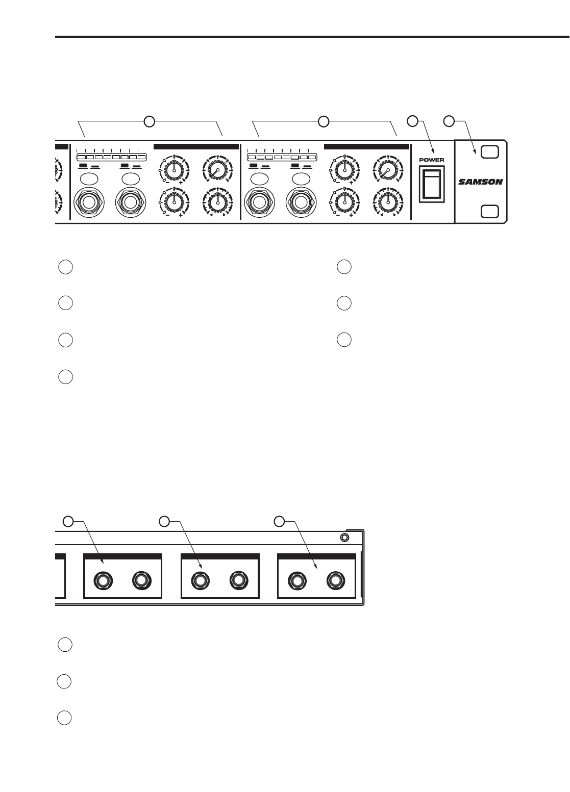
629991
1
Verklein
Vergroot
Pagina terug
1/19
Pagina verder
5
10OFF
MASTER
VOLUME
INJECT
MASTER LEVEL dB
-30 -18 -12-24 -6 +6 CLIP
0
CHANNEL 1
CHANNEL LEVEL dB
-30 -18 -12-24 -6 -3 CLIP0
MUTE / ON ST / 2CH
PHONES AUX IN
CHANNEL 2
CHANNEL LEVEL dB
-30 -18 -12-24 -6 -3 CLIP0
MUTE / ON ST / 2CH
PHONES AUX IN
CHANNEL 3
AUX MAIN
CHANNEL LEVEL dB
-30 -18 -12-24 -6 -3 CLIP0
MUTE / ON ST / 2CH
PHONES AUX IN
CHANNEL 4
CHANNEL LEVEL dB
-30 -18 -12-24 -6 -3 CLIP0
MUTE / ON ST / 2CH
PHONES AUX IN
POWER
HF
0
12
88
44
12
LF
12
88
4
12
4
PAN
LR
VOLUME
5
0
10
AUX MAIN
HF
0
12
88
44
12
LF
12
88
4
12
4
PAN
LR
VOLUME
5
0
10
AUX MAIN
HF
0
12
88
44
12
LF
12
88
4
12
4
PAN
LR
VOLUME
5
0
10
AUX MAIN
HF
0
12
88
44
12
LF
12
88
4
12
4
PAN
LR
VOLUME
5
0
10
HEADPHONE
MIXER/AMP
AUX MAIN
S Class Signal Processors
HEADPHONE MIXER/AMP
Safety Instructions
WARNING
DO NOT EXPOSE THIS EQUIPMENT
TO RAIN OR MOISTURE
AVIS
RISQUE DE CHOC ELECTRONIQUE
NE PAS OUVRIR
RISK OF ELECTRIC SHOCK
DO NOT OPEN
CAUTION
FOR CONTINUED PROTECTION AGAINST RISK
OF FIRE, REPLACE ONLY WITH SAME TYPE FUSE
ATTENTION
UTILISER UN FUSIBLE DE
RECHANGE DE MÊME TYPE
Important Safety Instructions
1. Please read all instructions before operating the unit.
2. Keep these instructions for future reference.
3. Please heed all safety warnings.
4. Follow manufacturers instructions.
5. Do not use this unit near water or moisture.
6. Clean only with a damp cloth.
7. Do not block any of the ventilation openings. Install in accordance with the manufacturers instructions.
8. Do not install near any heat sources such as radiators, heat registers, stoves, or other apparatus (including
amplifiers) that produce heat.
9. Do not defeat the safety purpose of the polarized or grounding-type plug. A polarized plug has two blades with
one wider than the other. A grounding type plug has two blades and a third grounding prong. The wide blade or
third prong is provided for your safety. When the provided plug does not fit your outlet, consult an electrician for
replacement of the obsolete outlet.
10. Protect the power cord from being walked on and pinched particularly at plugs, convenience receptacles and at
the point at which they exit from the unit.
11. Unplug this unit during lightning storms or when unused for long periods of time.
12. Refer all servicing to qualified personnel. Servicing is required when the unit has been damaged in any way,
such as power supply cord or plug damage, or if liquid has been spilled or objects have fallen into the unit, the
unit has been exposed to rain or moisture, does not operate normally, or has been dropped.
Caution: To reduce the hazard of electrical shock,
do not remove cover or back.
No user serviceable parts inside. Please refer all ser-
vicing to qualified personnel.
WARNING: To reduce the risk of fire or electric shock, do not expose this unit to rain or moisture.
The lightning flash with an arrowhead symbol within an equilateral triangle, is intended to alert the
user to the presence of uninsulated "dangerous voltage" within the products enclosure that may be of
sufficient magnitude to constitute a risk of electric shock to persons.
The exclamation point within an equilateral triangle is intended to alert the user to the presence of
important operating and maintenance (servicing) instructions in the literature accompanying the prod-
uct.
1
Table of Contents
Introduction 2
S•phone Features 3
Controls and Functions
Front Panel Layout
Rear Panel Layout 4-5
Operating the S•phone
Setting Up the S•phone 6-7
S•phone Master section 7
S•phone Channels 8
Stereo and Two Channel Modes 9
S•phone Connections
Cue Mix Set-up for Multitrack Vocal Recording 10
Cue Mix Set-up for Multitrack Rhythm section Recording 11
Linking Multiple S•phones 12
Headphone Impedance and Sensitivity ratings 13
S•phone Wiring Guide 14
Specifications 15-16
Block Diagram 17
Copyright 2001, Samson Technologies Corp.
Printed May, 2001
Samson Technologies Corp.
575 Underhill Blvd.
P.O. Box 9031
Syosset, NY 11791-9031
Phone: 1-800-3-SAMSON (1-800-372-6766)
Fax: 516-364-3888
www.samsontech.com
2
Congratulations on purchasing the Samson S•phone Headphone Amplifier! Although this unit
is designed for easy operation, we suggest you take some time out first to go through these
pages so you can fully understand how we’ve implemented a number of unique features. The
S•phone is a compact, high-quality device that allows you to monitor any stereo or monophon-
ic source signal (balanced or unbalanced) over as many as twelve separate headphones.
Providing unusually high power levels and superb audio fidelity, the S•phone is compatible with
virtually all popular headphone models. Front panel controls include a Master Input Level con-
trol and Stereo/2 Channel switch. Each headphone output has its own individual HIGH & LOW
Frequency EQ, an Insert jack, and Level control. Special output jacks on the rear panel allows
any number of S•phone units to be linked together with no loss of signal. The S•phone can be
used in a wide variety of applications, including recording studios, teaching labs, broadcast
environments, and for live performance. In this manual, you’ll find a more detailed description
of the features of the S•phone, as well as a guided tour through the front and rear panels,
step-by-step instructions for using the S•phone, a reference chart that gives impedance and
sensitivity ratings for a number of popular headphone models, and full specifications. You’ll
also find a warranty card enclosed—please don’t forget to fill it out and mail it so that you can
receive online technical support and so we can send you updated information about other
Samson products in the future.
With proper care and adequate air circulation, your S•phone will operate trouble free for many
years. We recommend you record your serial number in the space provided below for future
reference.
Serial number:
Date of purchase:
Should your unit ever require servicing, a Return Authorization number (RA) must be obtained
before shipping your unit to Samson. Without this number, the unit will not be accepted.
Please call Samson at 1-800-3SAMSON (1-800-372-6766) for a Return Authorization number
prior to shipping your unit. Please retain the original packing materials and if possible, return
the unit in the original carton and packing materials.
Introduction
3
S•phone Features
The Samson S•phone headphone amplifier utilizes the latest technology in gain management design. Here are
some of it’s features:
Four channel headphone mixer amplifier.
Three headphone outputs; two rear, plus one front panel output per channel.
Two master stereo inputs with balance control.
Dual band equalizer on each channel.
5 segment LED meter on each channel plus master.
Auxiliary input, with level control, on each channel for "More Me" mixing.
Stereo or dual input mode and mute switches on each channel.
Maximum output power on each channel regardless of headphone impedance.
Three year extended warranty.
5
10OFF
MASTER
VOLUME
INJECT
MASTER LEVEL dB
-30 -18 -12-24 -6 +6 CLIP
0
CHANNEL 1
CHANNEL LEVEL dB
-30 -18 -12-24 -6 -3 CLIP0
MUTE / ON ST / 2CH
PHONES AUX IN
CHANNEL 2
CHANNEL LEVEL dB
-30 -18 -12-24 -6 -3 CLIP0
MUTE / ON ST / 2CH
PHONES AUX IN
CHANNEL 3
AUX MAIN
CHANNEL LEVEL dB
-30 -18 -12-24 -6 -3 CLIP0
MUTE / ON ST / 2CH
PHONES AUX IN
CHANNEL 4
CHANNEL LEVEL dB
-30 -18 -12-24 -6 -3 CLIP0
MUTE / ON ST / 2CH
PHONES AUX IN
POWER
HF
0
12
88
44
12
LF
12
88
4
12
4
PAN
LR
VOLUME
5
0
10
AUX MAIN
HF
0
12
88
44
12
LF
12
88
4
12
4
PAN
LR
VOLUME
5
0
10
AUX MAIN
HF
0
12
88
44
12
LF
12
88
4
12
4
PAN
LR
VOLUME
5
0
10
AUX MAIN
HF
0
12
88
44
12
LF
12
88
4
12
4
PAN
LR
VOLUME
5
0
10
HEADPHONE
MIXER/AMP
AUX MAIN
4
5
10OFF
MASTER
VOLUME
INJECT
MASTER LEVEL dB
-30 -18 -12-24 -6 +6 CLIP0
CHANNEL 1
CHANNEL LEVEL dB
-30 -18 -12-24 -6 -3 CLIP0
MUTE / ON ST / 2CH
PHONES AUX IN
CHANNEL 2
CHANNEL LEVEL dB
-30 -18 -12-24 -6 -3 CLIP0
MUTE / ON ST / 2CH
PHONES AUX IN
C
-30 -2
4
MUTE
/
PHON
AUX MAIN
HF
0
12
88
44
12
LF
12
88
4
12
4
PAN
L
R
VOLUME
5
010
AUX MAIN
HF
0
12
88
44
12
LF
12
88
4
12
4
PAN
L
R
VOLUME
5
010
HEADPHONE
MIXER/AMP
AUX MAIN
4
9
10
11
12
1413
15
16
17
1
3
2
CHANNEL 4
OUTPUTS
CHANNEL 3
OUTPUTS
CHANNEL 2
OUTPUTS
HEADPH
O
N
E
MIXER
/
AM
P
MADE IN CHINA
MINIMUM IMPEDANCE 8 OHMS MINIMUM IMPEDANCE 8 OHMS MINIMUM IMPEDANCE 8 OHMS
A B
C
D E
1 MASTER LEVEL METER - Indicates the amount of sig-
nal being driven into the four channels from the mas-
ter volume control.
2 MASTER VOLUME - Controls the level being sent to
the individual channels.
3 CHANNEL LEVEL METER - Displays the amount of
power being supplied to the channels.
4 HEADPHONE CHANNEL 2 - The same knob and
switch compliment as Channel 1 is duplicated for
Channel 2.
5 HEADPHONE CHANNEL 3 - The same knob and
switch compliment is duplicated for Channel 3.
6 HEADPHONE CHANNEL 4 - The same knob and
switch compliment is duplicated for Channel 4.
7 MAIN POWER SWITCH - When turned on, activates
the S•phone.
8 RACK EARS - Used for mounting into a standard 19
inch rack.
9 MASTER INJECT - Stereo TRS front panel input for
injecting a signal into the main mix.
10 MUTE SWITCH - Used for muting the signal on the
individual channels.
A AC INLET - IEC standard AC power cable connector
with external fuse.
B CHANNEL 4 OUTPUTS - 2 rear panel headphone
outputs for Channel 4.
C CHANNEL 3 OUTPUTS - 2 rear panel headphone
outputs for Channel 3.
D CHANNEL 2 OUTPUTS - 2 rear panel headphone out-
puts for Channel 2.
Controls and Functions
REAR PANEL LAYOUT
FRONT PANEL LAYOUT
5
CHANNEL 1
OUTPUTS
LINK OUTPUT MAIN INPUT
LEFT LEFTRIGHT RIGHT
S
MINIMUM IMPEDANCE 8 OHMS
LEFT MONO
E
F G
CHANNEL 3
AUX MAIN
CHANNEL LEVEL dB
-30 -18 -12-24 -6 -3 CLIP0
MUTE / ON ST / 2CH
PHONES AUX IN
CHANNEL 4
CHANNEL LEVEL dB
-30 -18 -12-24 -6 -3 CLIP0
MUTE / ON ST / 2CH
PHONES AUX IN
POWER
HF
0
12
88
44
12
LF
12
88
4
12
4
PAN
L
R
VOLUME
5
010
MAIN
R
E
10
AUX MAIN
HF
0
12
88
44
12
LF
12
88
4
12
4
PAN
L
R
VOLUME
5
010
5 6
7
8
11 HEADPHONE OUTPUT - A front panel headphone
output for each channel.
12 ST/2CH SWITCH - Switches between stereo and 2
channel modes.
13 AUX IN - Used to inject a "MORE ME" signal into the
individual amp channels.
14 HIGH FREQUENCY EQ - Controls the amount of high
frequency EQ applied to headphone output.
15 LOW FREQUENCY EQ - Controls the amount of
low frequency EQ applied to headphone output.
16 VOLUME CONTROL - Controls the volume to the
headphone output for the individual channel.
17 PAN CONTROL - Controls the balance from left to
right in stereo mode and from aux to main mode.
E CHANNEL 1 OUTPUTS - 2 rear panel headphone outputs
for Channel 1.
F LINK OUTPUTS - Outputs that are tied to the main input
for linking to another headphone amp or other device.
G MAIN INPUT - The main signal input to the headphone
amp. Plugging into the left jack only sends the signal to
both the left and right.
Controls and Functions
6
Operating the S•phone
SETTING UP THE S•phone
Setting up your S•phone Headphone Amplifier is a simple procedure, which takes only a few minutes.
Remove all packing materials (save them in case of need for future service) and plug the provided AC power cord
in the rear AC inlet, but don’t plug the power cable into a wall outlet just yet.
Connect the output from the device you want monitored to the Left/Right MAIN INPUT jacks on the
S•phone rear panel. The S•phone accepts both balanced and unbalanced signal. Generally, a balanced
signal is preferable because it provides better signal-to-noise ratio and reduced extraneous noise.
Set the controls to the following positions:
MASTER VOLUME – OFF
CHANNEL 1 MUTE SWITCH – OUT
CHANNEL 1 ST/2CH SWITCH – OUT
CHANNEL 1 HIGH FREQUENCY – 0
CHANNEL 1 LOW FREQUENCY – 0
CHANNEL 1 PAN – CENTER, 12:00
CHANNEL 1 VOLUME – O
CHANNEL 2 - 4’s Controls - Set the Same as Channel 1
5
10OFF
MASTER
VOLUME
INJECT
MASTER LEVEL dB
-30 -18 -12-24 -6 +6 CLIP0
CHANNEL 1
CHANNEL LEVEL dB
-30 -18 -12-24 -6 -3 CLIP0
MUTE / ON ST / 2CH
PHONES AUX IN
C
-30 -2
4
MUTE
/
PHON
AUX MAIN
HF
0
12
88
44
12
LF
12
88
4
12
4
PAN
L
R
VOLUME
5
010
HEADPHONE
MIXER/AMP
Turn the Master Volume knob and all four headphone Channel Output knobs to their minimum (fully
counterclockwise) setting.
Plug the S•phone power cable into a wall outlet and switch the unit on by pressing the power switch.
Apply a signal, like the output of a mixer playing a CD, to the S•Phone’s rear-panel Left/Right MAIN
INPUT jacks. Raise the MASTER VOLUME until the meter reaches -18 to -12 dB.
Connect a set of headphones to Channel 1 and slowly turn the channel’s Volume knob clockwise until
you hear the desired level.
WARNING: Because the S•Phone is capable of generating extremely high volume levels, always start with the
Channel Volume knob at minimum and then slowly turn it up.
Operating the S•phone
Repeat the previous step for all Channels that have headphones connected, making sure to start the
VOLUME knob completely counterclockwise and then slowly raising it until the desired level is achieved.
If you have connected different models of headphones to the various Channel Headphone jacks, you
may find that some require more gain than others to achieve the same volume. This kind of disparity will
occur if the various headphones have different impedances. The lower the impedance, the louder the
headphone will sound compared to another, higher impedance headphone at the same VOLUME setting.
Another factor affecting headphone loudness is called sensitivity. This is generally measured by deter-
mining the decibel (dB) level generated by 1 mW of power input. The higher the dB rating, the louder the
headphone. See the Reference chart on page 16 of this manual for more details.
To achieve optimum signal-to-noise ratio, the MASTER VOLUME should generally be set as high as pos-
sible, short of audible distortion. However, if this results in your getting blasted with signal even though
the channel volume is near minimum, you’ll need to decrease the Master Volume while raising one or
more channel volume levels. Conversely, if you find that you have to raise one or more headphone
Channel Volume knobs to maximum or near maximum to achieve the desired level, try increasing the
Master Volume Level while decreasing the channel volume(s).
SETTING UP THE S•phone - Continued
S • Phone Master Section
Master Volume
The S phone’s MASTER VOLUME control is used to
adjust the input signal connected to the MAIN Left and
Right inputs. In addition, the MASTER VOLUME control
adjusts the level of the signal inserted in the MASTER
INJECT, which is summed with the MAIN Left and Right
input signal.
Master Level meter
The S•phone’s maser section includes an 8 segment LED
LEVEL meter which monitors the input level of the MAIN
Left and Right Inputs in Decibels (dBs) from –30 to CLIP.
If the LEVEL meter displays a CLIP signal, then turn down
the signal being sent into the MAIN left and Right.
5
10OFF
MASTER
VOLUME
INJECT
MASTER LEVEL dB
-30 -18 -12-24 -6 +6 CLIP0
HEADPHONE
MIXER/AMP
AUX MAIN
1
2
3
Using the Master Inject
The S•phone’s MASTER INJECT is a TRS input (Tip, Ring, Sleeve) that allows a second stereo signal to be
inserted and summed together with the MAIN Left and Right signals. You can use a stereo signal from your mix-
ers buss outputs or auxiliary sends to balance the mix between two stereo signals like rhythm tracks and vocals.
3
1
2
7
8
Headphone Output
The S•phone’s Headphone Output jack accepts
a standard 1/4” TRS connector for easy inter-
face with most professional headphones. Once
the MASTER VOLUME has been set, the chan-
nels output level is set by the VOLUME knob.
Channel MUTE Switch
The S•phone features Mutes Switches on each
of the four channels. When engaged, the LED
illuminates and indicates that the channel out-
put is turned off.
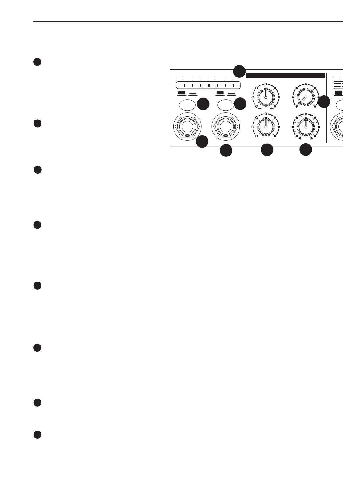
ST/2-CH Stereo Two Channel Switch
Each of the S•phone’s four channels can be set to operate in two modes: Stereo and Two-Channel. In stereo,
mode all signals inserted into the signal path including the MAIN, MASTER INJECT and Channel AUX input,
maintain their stereo image. In 2-Channel mode, the signals are all summed to mono and the PAN control now
becomes the balance between the MAIN stereo mix and the AUX input. More info on 2-Channel mode on page
11 of this manual.
AUX Input
Each of the S phones four Channels features an AUX input for inserting a signal directly into that channels head-
phone amp. The AUX input is particularly useful for adding a solo instrument or vocal send. In this case, the AUX
input is mixed with the MAIN mix so that listeners on that channel can have their own balance between the MAIN
mix and their instrument or vocal. This is commonly known as "More-Me" cue mixing. Depending on the status of
the STEREO/2-CHANNEL switch, the AUX level is adjusted at the signal source, like the aux send from a mixer,
or by using the PAN control.
Using the Channel EQ
Each of the four S•phone channels feature a two-band equalizer allowing individual tone settings on each
channel. The LOW Frequency EQ control provides up to 12 dB of CUT or BOOST at 100Hz. You’ll notice a single
detent when the control knob is located in the center of its travel range indicating that there is no boost or cut and
that the LOW frequency response of the channel is flat. The HIGH Frequency EQ control provides up to 12 dB of
CUT or BOOST at 10kHz. You’ll notice a single detent when the control knob is located in the center of its travel
range indicating that there is no boost or cut and that the HIGH frequency response of the channel is flat.
PAN Control
Each of the S•phone’s four channels has a PAN control which controls how much signal is sent to the left or right
headphone output. The control knob has a center detent which indicates that the left and right sides are bal-
anced. In 2 Channel mode, the signal becomes mono and the PAN knob adjusts the balance between the MAIN
(plus MASTER INJECT mix) and the Channel AUX input. (For more information on 2 Channel mode, see the sec-
tion “Mixing Signals in 2 Channel Mode” found on page 11 of this manual.)
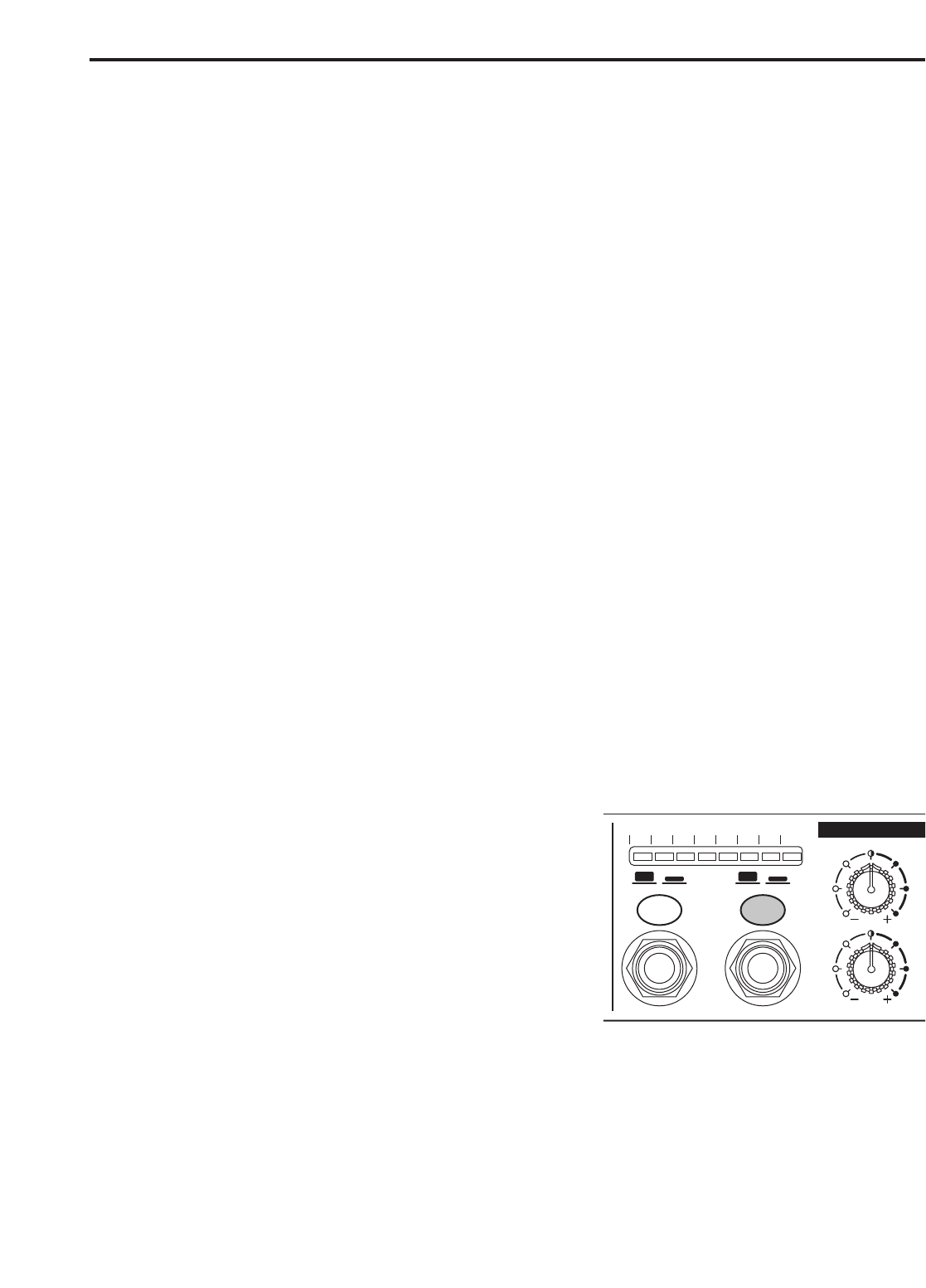
VOLUME Control
The Channel VOLUME control is used to adjust the channel headphone output. The Volume control will adjust
the level of the front panel headphone outputs, as well as, that channel’s rear panel headphone outputs.
CHANNEL LEVEL Meter
Each S•phone Channel has an 8 segment LED LEVEL meter which monitors the output of the channel in
Decibels (dBs) –30 to CLIP. If the LEVEL meter displays a CLIP signal, then turn down the Channel VOLUME,
and if necessary, also turn down the MASTER VOLUME .
CHANNEL 1
CHANNEL LEVEL dB
-30 -18 -12-24 -6 -3 CLIP0
MUTE / ON ST / 2CH
PHONES AUX IN
-30 -
MUT
PH
AUX MAIN
HF
0
12
88
44
12
LF
12
88
4
12
4
PAN
L
R
VOLUME
5
010
1
2
3
4
5
8
7
6
S • PHONE CHANNELS
3
2
4
5
6
7
1
8
Operating the S•phone
9
Operating the S•phone
STEREO AND TWO-CHANNEL MODES
Each of the S•phone’s four channels can be set to operate in two different modes: Stereo and 2 Channel.
Stereo Mode
Stereo mode is a normal operating mode where all mix inputs including MAIN, MASTER INJECT, as well as the
Channel AUX input, maintain their stereo image throughout the signal path to each headphone output. The indi-
vidual Channel’s PAN control is used to adjust the balance between the Left and Right side. To design a monitor
mix in the Stereo mode, follow these steps:
Press the ST/2CH switch to the OUT positions, you’ll notice the switch LED is not illuminated indicating
that Channel 1 is in STEREO mode.
Make a Stereo connection from your mixer’s auxiliary or buss outputs to the MAIN Left and Right inputs
on the S•phone’s rear panel.
Make a Stereo connection from your mixer’s auxiliary or buss outputs to the MASTER INJECT input on
the S•phone’s front panel.
Make a Stereo connection from your mixer’s auxiliary or buss outputs to the Channel 1 AUX input located
on the S•phone’s front panel.
In the Stereo mode, you adjust the mix balance between the MAIN, MASTER INJECT mix and the
Channel AUX input at your mixer by balancing the combinations of auxiliary and bus sends you have con-
nected to the S•phone.
Mixing Signals in 2 Channel Mode
In 2 Channel mode, all mix inputs including MAIN, MASTER INJECT, as well as the Channel AUX input are
summed to a mono signal. In this mode, the individual Channel’s PAN control is used to adjust the balance
between the MAIN( which includes the MASTER INJECT), and the channel AUX input. To design a monitor mix
in the 2 Channel mode follow these steps:
Press the ST/2CH switch to the IN positions, you’ll notice the
switch LED is now illuminated indicating that Channel I is in
2- Channel mode.
Make a Stereo connection from your mixer’s auxiliary or buss
outputs to the MAIN Left and Right inputs on the S•phone’s
rear panel.
If a second mix is desired, make a Stereo connection from
your mixer’s auxiliary or buss outputs to the MASTER
INJECT located on the S•phone’s front panel.
Make a Stereo connection from your mixer’s auxiliary or buss outputs to the Channel 1 AUX input located
on the S•phone’s front panel.
In the 2-CH mode you adjust the mix balance between the MAIN, MATER INJECT mix and the Channel
AUX input at your mixer by balancing the combinations of auxiliary and bus sends you have connected to
the S•phone.
CHAN
N
CHANNEL LEVEL dB
-30 -18 -12-24 -6 -3 CLIP0
MUTE / ON ST / 2CH
PHONES AUX IN
HF
0
12
88
44
12
LF
12
88
4
12
4
N
1

Hulp nodig? Stel uw vraag in het forum

Spelregels

Misbruik melden

Gebruikershandleiding.com neemt misbruik van zijn services uitermate serieus. U kunt hieronder aangeven waarom deze vraag ongepast is. Wij controleren de vraag en zonodig wordt deze verwijderd.

Product:

Bijvoorbeeld antisemitische inhoud, racistische inhoud, of materiaal dat gewelddadige fysieke handelingen tot gevolg kan hebben.

Bijvoorbeeld een creditcardnummer, een persoonlijk identificatienummer, of een geheim adres. E-mailadressen en volledige namen worden niet als privégegevens beschouwd.

Spelregels forum

Om tot zinvolle vragen te komen hanteren wij de volgende spelregels:

Belangrijk! Als er een antwoord wordt gegeven op uw vraag, dan is het voor de gever van het antwoord nuttig om te weten als u er wel (of niet) mee geholpen bent! Wij vragen u dus ook te reageren op een antwoord.

Belangrijk! Antwoorden worden ook per e-mail naar abonnees gestuurd. Laat uw emailadres achter op deze site, zodat u op de hoogte blijft. U krijgt dan ook andere vragen en antwoorden te zien.

Abonneren

Abonneer u voor het ontvangen van emails voor uw Samson S.phone bij:


U ontvangt een email met instructies om u voor één of beide opties in te schrijven.


Ontvang uw handleiding per email

Vul uw emailadres in en ontvang de handleiding van Samson S.phone in de taal/talen: Engels als bijlage per email.

De handleiding is 0,95 mb groot.


U ontvangt de handleiding per email binnen enkele minuten. Als u geen email heeft ontvangen, dan heeft u waarschijnlijk een verkeerd emailadres ingevuld of is uw mailbox te vol. Daarnaast kan het zijn dat uw internetprovider een maximum heeft aan de grootte per email. Omdat hier een handleiding wordt meegestuurd, kan het voorkomen dat de email groter is dan toegestaan bij uw provider.

Stel vragen via chat aan uw handleiding

Stel uw vraag over deze PDF

Uw handleiding is per email verstuurd. Controleer uw email

Als u niet binnen een kwartier uw email met handleiding ontvangen heeft, kan het zijn dat u een verkeerd emailadres heeft ingevuld of dat uw emailprovider een maximum grootte per email heeft ingesteld die kleiner is dan de grootte van de handleiding.

Er is een email naar u verstuurd om uw inschrijving definitief te maken.

Controleer uw email en volg de aanwijzingen op om uw inschrijving definitief te maken

U heeft geen emailadres opgegeven

Als u de handleiding per email wilt ontvangen, vul dan een geldig emailadres in.

Uw vraag is op deze pagina toegevoegd

Wilt u een email ontvangen bij een antwoord en/of nieuwe vragen? Vul dan hier uw emailadres in.


Info