die SPEAKER A-Taste als A/B-Wechselschalter, der zwischen den an die SPEAKER A- und SPEAKER B-Ausgänge
angeschlossenen Monitoren wählt.
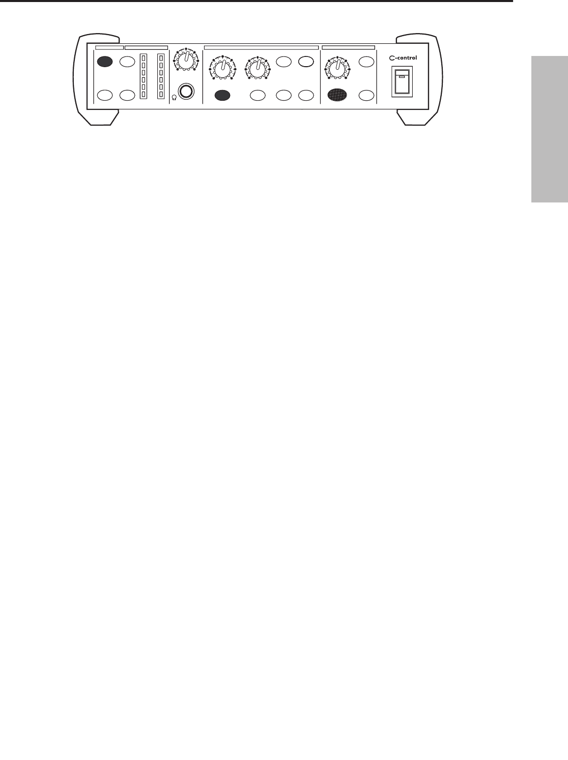
SPEAKER B-Zuordnungstaste
Bei gedrückter SPEAKER B-Taste (LED leuchtet) können Sie die SPEAKER B-Ausgänge einschalten, indem
Sie mit der SPEAKER A-Taste zwischen den SPEAKER A- und B-Ausgängen wechseln. Weitere Infos über
das Wechseln zwischen SPEAKER A und SPEAKER B finden Sie im vorherigen Abschnitt “SPEAKER A-
Zuordnungstaste”.
Speaker C-Zuordnungstaste/SUB
Damit schalten Sie die an die SPEAKER C-Ausgänge angeschlossen Monitore oder Subwoofer ein. Da die
SPEAKER C-Zuordnungstaste unabhängig von der SPEAKER A- und/oder SPEAKER B-Taste funk tioniert, lässt
sich an den entsprechenden Ausgang auch ein Subwoofer anschließen. Auf diese Weise können Sie den
Subwoofer nach Belieben ein- und ausschalten, während Sie die SPEAKER A- oder SPEAKER B-Monitore
abhören.
MIX2TK A
2TK C
2TK B
OL
+6
0
-6
-18
-30
LR
SPEAKER ASPEAKER C
MUTE
SPEAKER B
SUB
DIM
MONO
HEADPHONE
VOLUME
SPK
B
VOLUME
HEADPHONE
VOLUME
010
010
010
TALKBACK
LEVEL
MI
C
TALK TO
2TK
TALK TO
CUE
010
CONTROL ROOM
MATRIX
SAMSON
SOURCE
DESTINATION
LEVEL
CONTROL ROOM
TALKBACK
24
25
26
27
28
29
2425
26272829
DEUTSCHE
48
C•control bedienen
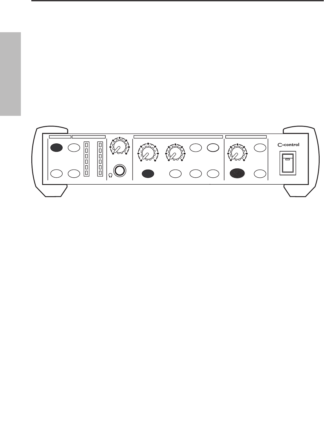
TALKBACK-SEKTION
TALKBACK-MIKROFON
Über das vorderseitige, interne Kondensatormikrofon können Sie eine Audio-Kennung auf die ange schlos-
senen 2-Spur-Maschinen aufnehmen oder mit Musikern und anderen Künstlern kommunizieren, die sich die
Mischung via EXTERNAL CUE-Ausgänge anhören. Die folgenden Abschnitte beschreiben, wie Sie das Signal
weiterleiten und den Pegel des TALKBACK MIKROFONS steuern.
Talk To 2-Track
Mit dieser Taste weisen Sie das TALKBACK MIC den 2-Spur Ausgängen zu. Auf diese Weise können die
Tontechniker/Produzenten im Studio-Kontroll raum eine Audio-Kennung auf eine
der angeschlossenen 2-Spur Recorder aufnehmen. Da die TALK TO 2-Track-Taste
nicht einrastet, müssen Sie sie gedrückt halten, während Sie sprechen oder auf
eine 2-Spur Maschine auf nehmen.
Talk To Cue
Mit dieser Taste weisen Sie das TALKBACK MIC dem EXTERNAL CUE-Ausgang zu.
Auf diese Weise können die Tontechniker/Produzenten im Studio-Kontroll raum
mit den Musikern im Aufnahmeraum kommunizieren. Da die TALK TO CUE-Taste
nicht einrastet, müssen Sie sie gedrückt halten, während Sie sprechen oder mit
dem TALKBACK MIC aufnehmen.
Talkback Level
Mit diesem Regler steuern Sie den Pegel des Signals, das vom internen TALKBACK MIKROFON auf genommen
wird. Da wahrscheinlich jemand den EXTERNAL CUE-Ausgang über Kopfhörer abhört, wenn Sie die TALK TO
CUE-Taste drücken, sollten Sie mit einem niedrigen Pegel beginnen. Beim Ein satz der Talk to 2-Track-Taste
sollten Sie den Pegel des TALKBACK MIKROFONs einstellen, indem Sie die Eingangspegel-Anzeigen der ang-
eschlossenen 2-Spur-Maschinen prüfen.
Talkback-Fernbedienungsfunktion einsetzen
Indem Sie einen nichtrastenden Schalter an die rückseitige TALK REMOTE-Buchse anschließen, können Sie die
Talkback-Taste fernbedienen. Mit einem normalen, in Ihrem lokalen Musikgeschäft erhält lichen Fußschalter
oder mit verdrahteten Fernbedienungsschaltern, wie dem Switchcraft SERIES ED900, können Sie die Talkback-
Schaltung bequem aktivieren, ohne die C control anzufassen. Es folgt ein Verdrahtungsdiagramm für den
REMOTE TALK-Schalter.
MIX2TK A
2TK C
2TK B
OL
+6
0
-6
-18
-30
LR
SPEAKER ASPEAKER C
MUTE
SPEAKER B
SUB
DIM
MONO
HEADPHONE
VOLUME
SPK
B
VOLUME
HEADPHONE
VOLUME
010
010
010
TALKBACK
LEVEL
MI
C
TALK TO
2TK
TALK TO
CUE
010
CONTROL ROOM
MATRIX
SAMSON
SOURCE
DESTINATION
LEVEL
CONTROL ROOM
TALKBACK
CONTROL ROOM
SAMSON
NICHTRASTENDER SCHALTER
MIT ARBEITSKONTAKT
VERDRAHTUNG DES REMOTE TALKBACK-SCHALTERS
Spitze (+)
Schirm (Schaltungsnull)
29
30
31
32
2930
3132
DEUTSCHE
49
C•control Typisches Setup
POWER
AC IN
14
V
SAMSON
MADE IN CHINA
+
-
500mA
MIX IN
2TK
A2TK B2TK C2TK A2TK B2TK C
L
R
L
R
R
L
SPK AEXT CUE
TALK
REMOTE
SPK
B
SPK
C
BALANCE
DBALANCED
BALANCEDBALANCED
BALANCEDBALANCEDBALANCED
INPUT
OUTPUT
MAIN
INJECT
2 CH
STEREO
SHAPE
OUT
SHAPE
OUT
0
10
0
10
CH 1
OL
0
-6
-12
-18
-24
OL
0
-6
-1
2
-1
8
-2
4
CH
1
CH
2
SHAPE
OUT
SHAPE
OUT
OL
0
-6
-12
-18
-24
CH 3CH
4
4 CHANNEL
HEADPHONE AM
P
CH 2
CH 3
CH 4
VOLUME
VOLUMEVOLUME
VOLUME
VOLUME
01
0
BALANCE
LR
01
0
01
0
01
0
01
0
®
®
®
®
PAN
0
LR
HF
12K
0
15
1010
55
15
MF
2.5K
15
1010
5
15
0
5
0
LF
80Hz
0
15
1010
5
15
5
0
30
5
-2
6
5
-26
60
+26
60
+26
CHANNEL 1CHANNEL 1CHANNEL 2CHANNEL 2
CHANNEL 3/4CHANNEL 3/4CHANNEL 5/6CHANNEL 5/6LL
RR
MIXMIX
MONO
MONO OU
T
AUX OUT
LINE IN
AUX RET
LEFT/MONO
RIGH
T
CR OUT
LEFT
RIGHT
MIX OUT
LEFT
RIGHT
LINE IN
AUX RETURN
C/ROO
M
+PHONES
MIC/LINE 1MIC/LINE 2
MIC/LINE 3/4
MIC/LINE 5/6
PHONES
LEFTRIGHTLEFTRIGHT
2T IN2T OUT
HDR
MIX/2T
PAN
0
LR
HF
12K
0
15
1010
55
15
MF
2.5K
15
1010
5
15
0
5
0
LF
80Hz
0
15
1010
5
15
5
0
30
BAL
0
LR
HF
12K
0
15
1010
55
15
MF
2.5K
15
1010
5
15
0
5
0
LF
80Hz
0
15
1010
5
15
5
0
BAL
0
LR
HF
12K
0
15
1010
55
15
MF
2.5K
15
1010
5
15
0
5
0
LF
80Hz
0
15
1010
5
15
5
0
5
01
0
5
01
0
2TK TO MIX
5
01
0
5
01
0
AUX
010
AUX
010
AUX
010
AUX
010
GAIN
CLIP
GAIN
CLIP
RECREC
RE
CREC
3/L
4/
R
5/
L
6/
R
MASTER SECTIONMASTER SECTION
MASTER SECTION
10
5
0
10
5
20
30
40
10
5
0
10
5
20
30
40
1515
10
5
0
10
5
20
30
40
10
5
0
10
5
20
30
40
1515
10
5
0
10
5
20
30
40
10
5
0
10
5
20
30
40
1515
10
5
0
10
5
20
30
40
10
5
0
10
5
20
30
40
1515
10
5
0
10
5
20
30
40
10
5
0
10
5
20
30
40
10
5
0
10
5
20
30
40
15
15
15
M AXIMUMDY N AMICRAN G E
PEAK
+6
0
-6
-20
POWER
48V
_
_
_
_
_
_
_
_
_
_
_
_
_
_
_
_
_
_
_
_
_
_
_
_
_
_
_
_
_
_
_
_
_
_
_
_
_
_
_
_
_
_
_
_
_
_
_
_
LINE-AUSGÄNGE
LINE-EINGÄNGE
LINE-EINGÄNGE
MIX-AUSGÄNGE
LINE-AUSGÄNGE
SIGNALFLUSS
SIGNALFLUSS
SIGNALFLUSS
SIGNALFLUSS
SIGNALFLUSS
SIGNALFLUSS
SIGNALFLUSS
SIGNALFLUSS
SIGNALFLUSS
SIGNALFLUSS
SIGNALFLUSS
SIGNALFLUSS
SIGNALFLUSS
SIGNALFLUSS
SIGNALFLUSS
SIGNALFLUSS
SIGNALFLUSS
SIGNALFLUSS
SIGNALFLUSS
SIGNALFLUSS
SOUNDKARTEN-
EINGÄNGE
SOUNDKARTEN-
AUSGÄNGE
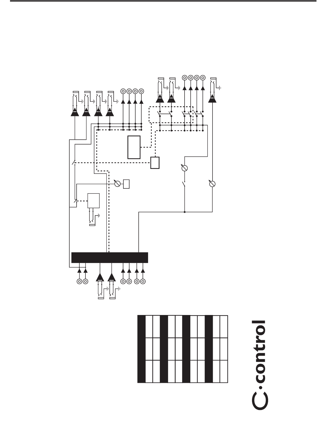
CUE-MISCHUNG FÜR GESANGS-MEHRSPURAUFNAHME EINRICHTEN
CUE-MISCHUNG FÜR GESANGS-MEHRSPURAUFNAHME EINRICHTEN
Das folgende Diagramm zeigt ein typisches Studio-Setup, bei dem die C control mit einem Mischer, zwei Studio-Monitorsets plus Subwoofer, einem DAT Recorder, einer MIDI Workstation, einem Kopfhörer-Verstärker
und dem Hard-Disk Recorder eines Computers verbunden ist. Da es viele Möglichkeiten zum Integrieren der C control gibt, wird Ihr Setup wahrscheinlich anders aussehen.
DEUTSCHE
50
C•control stapeln und kippen
Kippfüße installieren
Sie können die mit Ihrer C control gelieferten
Gummifüße installieren, um das auf einer Work -
station bzw. Schreibtisch stehende Gerät auf
einen angenehmen Betriebswinkel einzu stellen.
Gehen Sie hierbei wie folgt vor
.
• Entfernen Sie die untere Schraube von der
rechten vorderen Stütze
.
•
Suchen Sie den rechten Kippfuß – er ken -
nbar an der Positionierungsmarke “R” auf
der Innenseite oben
.
•
Setzen Sie den angewinkelten Fuß wie in
der Abbildung unter die rechte Stütze
.
•
Befestigen Sie den Fuß mit der mitge-
lieferten 4 x 10 mm Schraube
.
•
Wiederholen Sie die obigen Schritte beim
linken vorderen Fuß
.
MIX2TK A
2TK C
2TK B
OL
+6
0
-6
-18
-30
LR
SPEAKER ASPEAKER C
MUT
E
SPEAKER
B
SUB
DIM
HEADPHONE
VOLUME
SPK B
VOLUME
HEADPHONE
VOLUME
010
01
0
01
0
TALKBACK
L
MIC
TALK TO
2TK
TALK TO
CUE
010
CONTROL ROOM
MATRIX
SAMSON
SOURCE
DESTINATION
LEVEL
CONTROL ROOM
TA
LKBACK
LKBACK
01
LKBACK
01
LKBACK
LKBACK
C•controlstapeln
Sie können mehrere C control
oder andere Samson C Class
Geräte übereinander stapeln,
indem Sie einfach die Stützen
ausrichten.
Wichtige Anmer kung: Ach ten
Sie beim Stapeln meh rerer C
control darauf, dass nur beim
untersten Gerät die Kippfüße
installiert sind
.
•
Entfernen Sie die untere Schraube von der rechten vorderen Stütze.
•
Suchen Sie den rechten Kippfuß – erkennbar an der Positionierungsmarke “R” auf der
Innenseite oben
.
•
Setzen Sie den angewinkelten Fuß wie in der Abbildung unter die rechte Stütze.
MIX2TK A
2TK
C
2TK
B
OL
+6
0
-6
-18
-30
LR
SPEAKER ASPEAKER C
MUT
E
SPEAKER
B
SUB
DIM
MONO
HEADPHONE
VOLUME
SPK
B
VOLUME
HEADPHONE
VOLUME
010
010
010
TALKBACK
LEVEL
MI
C
TALK TO
2TK
TALK TO
CUE
010
CONTROL ROOM
MATRI
X
SAMSON
SOURCE
DESTINATION
LEVEL
CONTROL ROOM
TALKBACK
MIX2TK A
2TK
C
2TK
B
OL
+6
0
-6
-18
-30
LR
SPEAKER ASPEAKER C
MUT
E
SPEAKER
B
SUB
DIM
MONO
HEADPHONE
VOLUME
SPK
B
VOLUME
HEADPHONE
VOLUME
010
010
010
TALKBACK
LEVEL
MI
C
TALK TO
2TK
TALK TO
CUE
010
CONTROL ROOM
MATRI
X
SAMSON
SOURCE
DESTINATIO
N
LEVEL
CONTROL ROOM
TALKBACK
DEUTSCHE
51
C•control Verdrahtung
Spitze (Signal)
Schirm (Erde)
Spitze (Signal)
Schirm (Erde)
Spitze (Signal)
Schirm (Erde)
Spitze (Signal)
Schirm (Erde)
2
3
1
XLR-Stecker
Heifl (2)
Kalt (3)
Nullleiter (1)
R¸ckansichtLˆtpunkte
12
3
Spitze (Signal)
Schirm (Erde)
Kalt (Pol 3)
(ohne Verbindung)
Spitze (Signal)
Schirm (Erde)
Spitze (Signal)
Schirm (Erde)
Spitze (Signal)
Schirm (Erde)
1
3
2
2
3
1
Heifl
Kalt
XLR-Buchse
XLR-Stecker
Heifl (2)
Kalt (3)
Nullleiter (1)Nullleiter
Heifl
Kalt
Heifl (2)
Kalt (3)
Nullleiter (1)Nullleiter
LˆtpunkteR¸ckansicht
R¸ckansichtLˆtpunkte
12
3
21
3
Spitze (Signal)
Signal (Spitze)
Signal (Ring)
Signal (Spitze)
Signal (Ring)
Ring (Signal)
Schirm (Erde)
Erde
Erde
Spitze (Signal)
Signal (Spitze)
Signal (Ring)
Signal (Spitze)
Signal (Ring)
Ring (Signal)
Schirm (Erde)
Erde
Erde
Spitze (Signal)
Signal
Signal
Schirm (Erde)
Erde
Erde
Spitze (Signal)Signal
Signal
Schirm (Erde)
Erde
Erde
Asymmetrisches 1/4”- auf Cinch-Kabel
Asymmetrisches XLR- auf Cinch-Kabel
C control Verdrahtungshilfe
Abhängig vom genauen Monitoring-Setup gibt es mehrere Möglichkeiten, die C control anzuschließen. Gehen Sie beim
Verkabeln Ihres Monitorsystems nach den folgenden Diagrammen vor.
Symmetrisches XLR- auf XLR-Kabel
Symmetrisches 1/4”- auf 1/4”-Kabel
Asymmetrisches 1/4”- auf 1/4”-Kabel
Cinch- auf Cinch-Kabel
DEUTSCHE
52
Den C Class Dual Rack Adapter erhalten Sie als Sonderzubehör bei einem autorisierten Samson-Händler oder über
unsere Website: www.samsontech.com.
1. Entfernen Sie alle Kabel, die an das zu montierende C•Class Gerät angeschlossen sind, d. h. Neztkabel, Audiokabel,
Kopfhörer.
2. Richten Sie die Löcher im C•Rack auf die Löcher in der Unterseite des zu montierenden C•Class-Geräts aus. Befestigen
Sie das Gerät mit den mitgelieferten Kreuzschlitz M4 Schrauben wie in der Abbildung am Rack.
3. Wiederholen Sie bei Bedarf die Schritte 1 und 2, um das zweite C•Class-Gerät zu montieren.
4. Nachdem die Geräte im C• Rack montiert sind, können Sie die Baugruppe in einem Rack platzieren und mittels
Rackwinkeln sichern (Schrauben sind nicht im Lieferumfang enthalten).
5. Um das C•Class-Gerät aus dem C•Rack zu entfernen, kehren Sie die obigen Anweisungen um.
C•Class Rack Doppel-Adapter (optional)
Falls Probleme auftauchen oder Sie Unterstützung benötigen, setzen Sie sich bitte mit dem Samson Customer Service unter 1-
800-3SAMSON (1-800-372-6766), Montag bis Freitag von 9 - 17 Uhr (Standardzeit an der US-Ostküste) in Verbindung. Weitere
Informationen finden Sie auf unserer Website unter www.samsontech.com.
ESPAÑOL
¡Felicidades y gracias por la compra del C control, la Matriz de sala de control de Samson Audio! El C control
es una unidad compacta y de alta calidad que le ofrece una amplia gama de funciones de monitorización de
sala de control que hasta ahora solo podía encontrar en mesas de mezclas de grabación de gama alta. El C
control es la solución perfecta para la interconexión de todas sus fuentes de línea stereo incluyendo mesas de
mezclas, grabadoras de disco duro y de masterización con distintos tipos de monitores de sala. El C control le
ofrece cuatro grupos de entradas de línea stereo, un amplificador de auriculares con control de nivel y conmu-
tación para tres grupos de monitores de sala de control. El C control le ofrece también una sofisticada sección
de línea interior o Talkback, que incluye un micrófono condensador interno con la capacidad de dirigir la señal
de línea interior a las salidas de grabadora de masterización y a la
External Que
para los auriculares. Con una
conmutación completamente silenciosa y una calidad audio excelente, la ruta de señal del C control impre-
sionará hasta a los críticos más especializados.
Aunque esta unidad ha sido diseñada para que su manejo sea muy sencillo, le recomendamos que dedique
un mínimo tiempo a leer estas páginas de cara a que pueda entender completamente cómo usar cada una de
las funciones que hemos incluido. En este manual, encontrará una descripción detallada de todas las carac-
terísticas del C control, así como un recorrido guiado por sus paneles frontal y posterior, instrucciones paso-
a-paso acerca del uso del C control y especificaciones técnicas completas. También encontrará una tarjeta
de garantía—no olvide rellenarla y devolvérnosla por correo para que pueda tener acceso a soporte técnico
online y para que le podamos enviar información actualizada acerca de otros productos Samson en el futuro.
Con unos cuidados mínimos y una ventilación correcta, su C control le dará un perfecto resultado y sin averías
durante años. Le recomendamos que apunte en el espacio de aquí abajo su número de serie y fecha de com-
pra por si lo necesita para cualquier consulta en el futuro.
Número de serie:
Fecha de compra:
Si en algún momento esta unidad se estropea y ha de enviarla para su reparación, deberá solicitarnos un
número de Autorización de Devolución (RA) antes de enviar la unidad Samson. Ningún aparato es aceptado
sin este código. Póngase en contacto con Samson en el 1-800-3SAMSON (1-800-372-6766) para que le facili-
temos un número de Autorización de Devolución antes de enviarnos la unidad. Si es posible devuélvanos el
aparato dentro de su embalaje original, o perfectamente embalado caso de que no la haya guardado.
Introducción
53
ESPAÑOL
Funciones del C•control
El amplificador de auriculares C•control de Samson utiliza la tecnología más moderna en cuanto a diseño de gestión de la
ganancia. Aquí puede ver algunas de sus funciones:
• Selector de fuentes de entrada y de altavoces que le ofrecen un punto centralizado para el ruteo y escucha de
fuentes stereo con distintos altavoces monitores.
• Selector de línea de altavoces de tres posiciones que le ofrecen conmutación A/B o A/B + C.
• Puede usar tres entradas stereo / masterización (2 pistas) para conectar unidades DAT, CD, MINIDISK, sub-
mezcladores, dispositivos MIDI o cualquier otra fuente stereo con nivel de línea.
• Cuatro interruptores de fuente stereo que se utilizan para direccionar cualquiera de las fuentes stereo que tenga
conectadas a la salida de monitor.
• Salida de auriculares con control de nivel.
• Mando VOLUME de la sala de control que puede usar para ajustar el nivel global de los monitores conectados.
• Control SPEAKER 2 VOLUME que puede usar para igualar el volumen de SPEAKER 1 y de SPEAKER 2 de forma que
estén al mismo nivel para cuando vaya a cambiar del uno al otro.
• Micro Talkback (línea interior) con interruptor momentáneo TALK y control LEVEL para dar paso a la conversación
del técnico de mesa y/o del productor a los músicos a través de la salida CUE.
• Interruptor TALK TO CUE que cuando está activado dirige la señal del micrófono interno TALKBACK a la salida
CUE que permite al técnico de mesa y/o al productor hablar a los músicos que están al otro lado del cristal del
estudio.
• Interruptor TALK TO 2-TR que cuando está activado dirige la señal del micro TALKBACK interno a las salidas de
masterización o de 2 pistas lo que permite al técnico de mesa y/o al productor grabar una reseñas del tipo “ pista
siete del jingle para el anuncio tal” en la remezcla final.
• Interruptor Mono que se usa para comprobar la compatibilidad mono de las mezclas y que cuando está
activado hace que todas las fuentes de entrada sean sumadas en una señal mono.
• Interruptor Mono que le permite anular todas las entradas y salidas desde un único botón.
• Interruptor Dim que cuando está activado amortigua el nivel de todas las salidas en 20 dB.
• Entrada Main Mix Stereo para la conexión del equipo a la mesa de mezclas principal.
• Tres salidas de altavoces de nivel de línea, una de 6,3 mm balanceada y dos RCA no balanceadas.
• 4 entradas de nivel de línea stereo/dos pistas, tres de 6,3 mm balanceadas y una RCA no balanceada.
• Soportes laterales de goma con patas de tipo cuña que le permiten apilar varias unidades Samson de la clase C
una encima de otra o colocarlas ergonómicamente en la mejor posición para su manejo.
• Tres años de garantía ampliada.
MIX2TK A
2TK
C
2TK
B
OL
+6
0
-6
-18
-30
LR
SPEAKER ASPEAKER C
MUTE
SPEAKER B
SU
B
DIM
MONO
HEADPHONE
VOLUME
SPK B
VOLUME
HEADPHONE
VOLUME
010
010
010
TALKBACK
LEVE
L
MI
C
TALK TO
2TK
TALK TO
CU
E
010
CONTROL ROOM
MATRIX
SAMSON
SOURCE
DESTINATION
LEVEL
CONTROL ROOM
TALKBACK
54
ESPAÑOL
MIX2TK A
2TK C
2TK B
OL
+6
0
-6
-18
-30
LR
SPEAKER ASPEAKER C
MUTE
SPEAKER B
SUB
DIM
MONO
HEADPHONE
VOLUME
SPK B
VOLUME
HEADPHONE
VOLUME
010
010
010
TALKBACK
LEVE
L
MI
C
TALK TO
2TK
TALK TO
CUE
010
CONTROL ROOM
MATRIX
SAMSON
SOURCE
DESTINATION
LEVEL
CONTROL ROOM
TALKBACK
12
3
4
5
67
8
9
1011
121314
1516
17
18
19
1
INTERRUPTOR MIX SOURCE
- Se usa para asignar
la entrada MIX principal a las salidas SPEAKER, CUE
y HEADPHONE del C control.
2 2 TK A SOURCE
- Sirve para asignar la entrada 2-
track A a las salidas SPEAKER, CUE y HEADPHONE
del C control.
3 HEADPHONE VOLUME
- Ajusta el nivel de salida
del amplificador de auriculares interno.
4 CONTROL ROOM VOLUME
- Control de nivel
master de todas las salidas de altavoces.
5 SPEAKER B VOLUME
- Sirve para ajustar e igualar
el nivel de la salida SPEAKER B.
6 INTERRUPTOR MUTE
- Cuando lo active, todas las
salidas del C control serán desactivadas.
7 INTERRUPTOR DIM
- Cuando lo active, el nivel de
salida de la sala de control será disminuido en 20
dB.
8 TALKBACK LEVEL
- Se usa para controlar el nivel
de salida del micrófono Talk-back interno.
9 TALK TO CUE
- Cuando lo pulse, el micrófono
interno estará activo y la señal de salida del
mismo será enviada a la salida CUE.
10 2 TK B SOURCE
- Sirve para asignar la entrada 2-
track B a las salidas SPEAKER, CUE y HEADPHONE
del C control.
11 2 TK C SOURCE
- Se usa para asignar la entrada
2-track C a las salidas SPEAKER, CUE y HEADPHONE
del C control.
12 MEDIDOR DE NIVEL
- Medidor VU con seis
segmentos LED que le muestra el nivel de
entrada de –30 dB hasta OL (picos)
13
CLAVIJA HEADPHONE
- Entrada de auriculares
stereo standard de 6,3 mm que le permite
monitorizar la señal desde el amplificador de
auriculares interno del C control.
14 SPEAKER A
- Cuando lo pulse, este interruptor
activará las salidas SPEAKER A.
15 SPEAKER B
- Cuando lo pulse, este interruptor
activará las salidas SPEAKER A.
16 SPEAKER C/SUB
- Cuando lo pulse, este
interruptor activará las salidas SPEAKER A.
17 MICROFONO TALKBACK
- Micrófono
condensador interno que sirve para grabar o
enviar señales de aviso procedentes de la sala
de control.
18
TALK TO 2-TRACK
- Cuando lo pulse, el micro
TALK TO 2-TRACK - Cuando lo pulse, el micro TALK TO 2-TRACK
interno estará activo y la señal de salida del
mismo será dirigida a las salidas de 2 pistas.
19 POWER
- Interruptor de encendido.
Funciones y controles
PANEL FRONTAL
55
ESPAÑOL
POWER
AC IN
14 V
SAMSON
MADE IN CHINA
+
-
500mA
MIX IN
2TK
A2TK B2TK C2TK A2TK B2TK C
L
R
L
R
R
L
SPK AEXT CUE
TALK
REMOTE
SPK B
SPK C
BALANCEDBALANCED
BALANCE
DBALANCED
BALANCE
DBALANCEDBALANCED
INPUT
OUTPU
T
A
B
C
D
EF
G
HI
J
K
L
M
A ENTRADA AC
- Conecte aquí el cable de corriente
que se incluye con la unidad.
B
REMOTE TALK
-
Conector de 6,3 mm que
se usa para la conexión de un disparador
TALKBACK externo.
C EXTERNAL CUE
- Salida stereo con dos conectores
de 6,3 mm balanceados para el envio de la mezcla
izquierda y derecha del C control a un amplificador
de auriculares.
D SPEAKER C
- Salidas RCA stereo para la conexión
de monitores autoamplificados o de una etapa de
potencia de monitorización. Puede usarla también
para conectar un subwoofer exterior.
E SPEAKER B
- Salidas RCA stereo para la conexión
de una etapa de potencia de monitorización o un
par de monitores autoamplificados.
F SPEAKER A
- Salidas de 6,3 mm stereo
balanceadas para la conexión de una etapa de
potencia de monitorización o un par de monitores
autoamplificados.
G SALIDA 2-TRACK C
- Salidas RCA stereo para la
conexión de cualquier dispositivo de grabación de
–10 dBu de nivel, como la tarjeta de sonido de un
ordenador, minidisk o una grabadora de cassette
no profesional.
H SALIDA 2-TRACK B
- Salidas de 6,3 mm stereo
balanceadas para la conexión de dispositivo de
grabación de +4dBu de nivel, como una grabadora
DAT, tarjeta de sonido de ordenador o “tostadora”
de CDs.
Controles y Funciones
PANEL TRASERO
I SALIDA 2-TRACK A
- Salidas de 6,3 mm
stereo balanceadas para la conexión de
dispositivos de grabación de +4dBu de nivel,
como una grabadora DAT, tarjeta de sonido
de ordenador o “tostadora” de CDs.
J ENTRADA 2-TRACK C
- Entradas RCA stereo
para la conexión de cualquier fuente stereo
de –10 dBu de nivel, como una tarjeta de
sonido de ordenador, minidisk, reproductor
de CD o grabadora de cassette no profesional.
K ENTRADA 2-TRACK B
- Entradas de 6,3
mm stereo balanceadas para la conexión de
cualquier fuente stereo de +4 dBu de nivel,
como una grabadora DAT, tarjeta de sonido
de ordenador, “tostadora” de CDs o sub-
mezclador.
L ENTRADA 2-TRACK A
- Entradas de 6,3
mm stereo balanceadas para la conexión de
cualquier fuente stereo de +4 dBu de nivel,
como una grabadora DAT, tarjeta de sonido
de ordenador, “tostadora” de CDs o sub-
mezclador.
M ENTRADA MIX
- Entradas de 6,3 mm stereo
balanceadas para la conexión de cualquier
fuente stereo de +4 dBu de nivel, como su
mesa de mezclas principal o sistema de
grabación en disco duro.
56
ESPAÑOL
Arranque rápido
CONFIGURACION RAPIDA
La configuración y ajuste de su C control es un proceso muy sencillo que solo le llevará unos pocos minutos. Existen var-
ias formas de interconectar el C control con sus distintos montajes y equipos de grabación, por lo que dedique un tiem-
po en decidir qué dispositivos audio quiere conectar. La sección siguiente le muestra una configuración sencilla para un
estudio de grabación típico con una mesa de mezclas analógica y dos grupos de monitores autoamplificados de estudio.
Extraiga la unidad de su embalaje (pero conserve la caja y el resto de materiales por si ha de enviar la unidad para su
reparación en el futuro) y conecte el cable de corriente que se incluye en la entrada de corriente AC del panel trasero,
aunque no conecte todavía el otro extremo a una salida de corriente eléctrica.
• Ajuste los controles a las posiciones siguientes:
INTERRUPTOR MIX - PULSADO (LED ENCENDIDO)
INTERRUPTOR 2TK A - SIN PULSAR (LED APAGADO)
INTERRUPTOR 2TK B - SIN PULSAR (LED APAGADO)
INTERRUPTOR 2TK C - SIN PULSAR (LED APAGADO)
VOLUMEN HEADPHONE - 0
VOLUMEN CONTROL ROOM - 0
VOLUMEN CONTROL ROOM SPKR B - 0
INTERRUPTOR MUTE - OUT (LED APAGADO)
INTERRUPTOR DIM - OUT (LED APAGADO)
INTERRUPTOR SPEAKER A - PULSADO (LED ENCENDIDO)
INTERRUPTOR SPEAKER B - SIN PULSAR (LED APAGADO)
INTERRUPTOR SPEAKER C - SIN PULSAR (LED APAGADO)
NIVEL TALKBACK - O
INTERRUPTOR TALK TO CUE - SIN PULSAR (LED APAGADO)
INTERRUPTOR TALK TO 2TK - SIN PULSAR (LED APAGADO)
MIX2TK A
2TK C
2TK B
OL
+6
0
-6
-18
-30
LR
SPEAKER ASPEAKER C
MUT
E
SPEAKER B
SU
B
DIM
MONO
HEADPHONE
VOLUME
SPK B
VOLUME
HEADPHONE
VOLUME
010
010
010
TALKBACK
LEVEL
MI
C
TALK TO
2TK
TALK TO
CUE
010
CONTROL ROOM
MA
TRIX
SAMSON
SOURCE
DESTINATION
LEVEL
CONTROL ROOM
TALKBACK
• Conecte las salidas de su mesa de mezclas de la sala de control, o de la fuente stereo principal que quiera moni-
torizar a las clavijas de entrada MIX izquierda/derecha del panel trasero del C control. El C control acepta tanto
señales balanceadas como no balanceadas. Por lo general, es preferible que use señales balanceadas dado que
ofrecen una mejor calidad señal-ruido y reducen los ruidos extraños. Vaya a la página 17 de este manual si qui-
ere ver una guía en profundidad acerca del cableado.
• Conecte las salidas izquierda y derecha SPEALER A del C control a las entradas de los monitores autoamplifica-
dos principales. Las salidas SPEAKER A son balanceadas, pero puede usar tanto cables balanceados como no bal-
anceados. Por lo general, es preferible que use señales balanceadas dado que ofrecen una mejor calidad señal-
ruido y reducen los ruidos extraños. Vaya a la página 17 de este manual si quiere ver una guía en profundidad
acerca del cableado.
• Conecte las salidas izquierda y derecha SPEALER B del C control a las entradas de su etapa de potencia o moni-
tores autoamplificados.
• Conecte el cable de corriente del C control a una salida de corriente y encienda la unidad pulsando su interrup-
tor de encendido.
• Ahora, encienda su etapa de potencia o monitores de estudio autoamplificados y ajuste el control de nivel a sus
posiciones normales.
57
ESPAÑOL
Arranque rápido
• Conecte una señal stereo (como la salida de un reproductor de CD) a su mesa de mezclas y suba el nivel master
hasta aproximadamente los “0 dB”.
• Una vez que haya ajustado un buen nivel, suba el control de volumen de su mesa de mezclas de la sala de con-
trol hasta que el medidor LEVEL del C Control le muestre aproximadamente “0 dB”.
• Suba lentamente el control VOLUME de la sala de control del C control hasta que sus monitores principales de
estudio lleguen al nivel de audición que quiera.
• Para elegir los monitores secundarios, pulse el interruptor Speaker B de forma que su piloto verde se ilumine.
• Ahora, cuando pulse este interruptor SPEAKER B estará eligiendo los monitores secundarios y a la vez desco-
nectando los monitores principales.
• Suba lentamente el control SPK B LEVEL hasta que consiga el nivel que quiera.
Nota:
Si quiere ajustar los dos pares de monitores al mismo nivel, haga una conmutación A/B y utilice el control
SPK B LEVEL para ajustar el balance.
CONFIGURACION RAPIDA - Continuación
58
ESPAÑOL
Configuración del C•control
59
Conexión de grabadoras y fuentes de sonido stereo
Entradas del C control
El C control dispone de cuatro entradas stereo/2 pistas para la conexión de una amplia gama de fuentes de sonido
incluyendo la salida de su mesa de mezclas principal o tarjeta de sonido de ordenador, una grabadora DAT, grabadora
de bobina (sáquelas del trastero, siguen sonando muy bien), grabadora de cassette, reproductor CD, workstation MIDI o
submezcladores, por decir solo algunos. Cada una de las entradas stereo del C controls puede ser activada o desactivada
con los interruptores de asignación del panel frontal. Para una mayor flexibilidad, es posible tener cualquiera o todas las
entradas stereo/2 pistas a la vez. Esto es especialmente útil cuando conecte las salidas de una mesa de mezclas principal
o de una tarjeta de sonido de ordenador y las salidas de un submezclador o workstation MIDI ya que le permitirá moni-
torizar las fuentes de sonido y controlarlas como si fuesen una sola. Dado que el C control le ofrece muchas entradas y
salidas para la conexión de sus unidades, hay muchas formas para la interconexión de este aparato. La sección siguiente
describe las entradas stereo/2 pistas y la forma en que puede usarlas con los dispositivos habituales de un estudio de
grabación. También puede encontrar en la página 15 de este manual un diagrama de “configuración típica”, así como una
guía de cableado en la página 17 que le servirá de gran ayuda a la hora de escoger los cables correctos para su configu-
ración.
Entradas MIX
Las entradas MIX son las entradas stereo izquierda y derecha princi-
pales del C control. Estas entradas son balanceadas y están montadas
en conectores TRS (punta/anillo/lateral) de 6,3 mm que aceptan fuen-
tes de línea con un nivel de +4 dB. Conecte aquí las salidas de su mesa
de mezclas o tarjeta de sonido.
Entradas 2-track A
Las entradas 2-Track A son balanceadas y están montadas en conecto-
res TRS (punta/anillo/lateral) de 6,3 mm que aceptan fuentes de línea
con un nivel de +4 dB. Puede conectar aquí una unidad DAT o graba-
dora de CD profesional.
Entradas 2-track B
Las entradas marcadas como 2-Track B son balanceadas y están montadas en conectores TRS (punta/anillo/lateral) de 6,3
mm que aceptan fuentes de línea con un nivel de +4 dB. Puede conectar aquí las salidas de un submezclador, una uni-
dad DAT profesional o una grabadora de CD.
Entradas 2-track C
Las entradas 2-Track C son no balanceadas y están montadas en conectores RCA que aceptan fuentes de línea con un
nivel de -10 dBu. Puede conectar aquí las salidas de un submezclador, grabadora de cassette o una grabadora de CD.
POWER
AC IN
14 V
SAMSON
MADE IN CHINA
+
-
500mA
MIX IN
2TK
A2TK B2TK C2TK A2TK B2TK C
L
R
L
R
R
L
SPK AEXT CUE
TALK
REMOTE
SPK B
SPK
C
BALANCEDBALANCED
BALANCEDBALANCED
BALANCEDBALANCEDBALANCED
INPUT
OUTPUT
L
R
D
1
2
3
4
1234
ESPAÑOL
Configuración del C•control
60
Salidas de línea de 2 pistas del C control
El C control le ofrece tres salidas stereo/2 pistas que le permiten conectar las entradas de una amplia gama de dispositi-
vos de grabación como grabadoras DAT, grabadoras de bobina, grabadoras de cassette o reproductores / tostadoras de
CD. La señal que es asignada en la sección de fuente del C control está siempre presente a todo su volumen y no se ve
afectada por el mando de nivel de la sala de control. Para evitar problemas de bucles de realimentación, asegúrese de
hacer coincidir las salidas de 2 pistas con sus entradas correspondientes. En otras palabras, si conecta su grabadora DAT a
las entradas A de 2 pistas, asegúrese de conectar las salidas A de 2 pistas a las entradas de su grabadora DAT. El C control
le ofrece muchas entradas y salidas para la conexión de su equipo, por lo que puede conectar esta unidad de muchas
formas. La sección siguiente le describe las salidas de 2 pistas y la forma en que puede usarlas con los dispositivos que
encontrará normalmente en un estudio de grabación. También puede encontrar en la página 15 de este manual un dia-
grama de “configuración típica”, así como una guía de cableado en la página 17 que le servirá de gran ayuda a la hora de
escoger los cables correctos para su configuración.
Salidas 2-track A
Las salidas 2-Track A son balanceadas y están montadas en conectores TRS (punta/anillo/lateral) de 6,3 mm que dan
salida a una señal de línea con un nivel de +4 dB. Aquí puede conectar una grabadora DAT profesional, una pletina de
bobina o una “tostadora” de CDs.
Salidas 2-track B
Las salidas marcadas como 2-Track B son balanceadas y están montadas en conectores
TRS (punta/anillo/lateral) de 6,3 mm que dan salida a una señal de línea con un nivel de
+4 dB. Puede usar estas salidas para conectar las entradas de una pletina de cassette no
profesional o una grabadora de CD.
Salidas 2-track C
Las salidas 2-Track C son no balanceadas, están montadas en conectores RCA y dan salida
a una señal de línea con un nivel de -10dB. Puede usar estas salidas para conectar las
entradas de una pletina de cassette no profesional o una grabadora de CD.
Conexión de salidas de altavoz con nivel de línea
El C control le ofrece tres grupos de salidas de nivel de línea para la conexión de hasta tres parejas de monitores de estu-
dio. Las salidas Speaker son seleccionadas desde los interruptores de selección del panel frontal. Las salidas de altavoz A
y B están conmutadas y se utilizan habitualmente para realizar comparaciones entre una pareja de monitores de campo
cercano y una de campo medio o lejano. La salida de altavoces C/Sub puede ser activada o desactivada de forma inde-
pendiente, por lo que resulta ideal para la conexión de un subwoofer que puede activar por separado para conseguir un
sonido más “potente”, pero que también puede desactivar para mezclas en las que el control del sonido resulte crítico.
Puede encontrar más información acerca de la función de conmutación de altavoces en la sección “Manejo del C control”
de este manual, un poco más adelante. También puede encontrar en la página 15 de este manual un diagrama de “con-
figuración típica”, así como una guía de cableado en la página 17 que le servirá de gran ayuda a la hora de escoger los
cables correctos para su configuración.
POWER
AC IN
14 V
SAMSON
MADE IN CHINA
+
-
500mA
MIX IN
2TK
A2TK B2TK C2TK A2TK B2TK C
L
R
L
R
R
L
SPK AEXT CUE
TALK
REMOTE
SPK B
SPK C
BALANCEDBALANCED
BALANCEDBALANCED
BALANCEDBALANCEDBALANCED
INPUT
OUTPUT
D
DB
OUTPUT
567
5
6
7
ESPAÑOL
Configuración del C•control
61
Speaker A
Las salidas Speaker A son balanceadas y están montadas en conectores TRS (punta/anillo/lateral) de 6,3 mm que dan
salida a una señal de línea con un nivel de +4 dB. Puede conectar estas salidas a unos monitores de estudio activos o a
una etapa de potencia.
NOTA IMPORTANTE:
De cara a mantener la mejor estructura de ganancia y relación señal-ruido posible, le recomenda-
mos que utilice solamente cables balanceados en las salidas SPEAKER A. Para una información más detallada sobre dia-
gramas de cableado, vea la página 17 de este manual.
Speaker B
Las salidas Speaker B son no balanceadas y están montadas en conectores RCA que dan salida a una señal de línea a un
nivel de -10 dBu. Puede conectarlas a un monitor de estudio activo, altavoz multimedia o etapa de potencia.
Speaker C
Las salidas Speaker C son no balanceadas y están montadas en
conectores RCA que dan salida a una señal de línea a un nivel
de -10 dBu. Puede conectarlas a un monitor de estudio activo,
altavoz multimedia o etapa de potencia.
Salida External Cue
Las salidas External Cue son balanceadas y están montadas en
conectores TRS (punta/anillo/lateral) de 6,3 mm y dan salida a
una señal de línea a un nivel de +4 dB. Esta salida se usa para
conectar la señal proveniente del micrófono Talkback o de
línea interior a su mezcla cue de auriculares. Muchos buenos amplificadores de auriculares como el C cue 8 o S phone de
Samson ofrecen una entrada auxiliar para que pueda mezclar la señal del micro talkback con la mezcla de escucha stereo
de su mesa de mezclas. Esta función permite al técnico de mesa y/o productor hablar a los músicos a través de la mezcla
de auriculares. Puede encontrar más información acerca de esta función en la sección “Manejo del C control” más adel-
ante en este manual.
TALK REMOTE
El micrófono TALKBACK del C control puede ser activado o desactivado desde un disparador exterior conectado a la
entrada TALK REMOTE. El cableado de esta entrada de 6,3 mm es del tipo “normalmente abierto”, por lo que un interrup-
tor que conmute la PUNTA del conector TALK REMOTE a su LATERAL activará o desactivará el micrófono TALKBACK de
forma momentánea. Esto permitirá al productor moverse libremente por el estudio mientras habla con los músicos.
AC INLET
A través de esta entrada AC el C control recibe su entrada de corriente eléctrica desde su fuente de alimentación interna
de 18 voltios AC. Asegúrese de usar solo el cable Samson AC1800 con el C control.
POWER
AC IN
14 V
SAMSON
MADE IN CHINA
+
-
500mA
MIX IN
2TK
A2TK B2TK C2TK A2TK B2TK C
L
R
L
R
R
L
SPK AEXT CUE
TALK
REMOTE
SPK B
SPK
C
BALANCEDBALANCED
BALANCEDBALANCED
BALANCEDBALANCEDBALANCED
INPUT
OUTPUT
8
9
10
11
12
13
891011
13
12
ESPAÑOL
Manejo del C•control
62
Manejo del C Control
Una vez que haya conectado sus grabadoras stereo, fuentes de sonido stereo y monitores de estudio puede comenzar a
utilizar y a disfrutar de las increíbles características del C control. La sección siguiente le enseñará el manejo de los inter-
ruptores, mandos y funciones operativas del C control.
Controles y Funciones
Interruptor POWER
Utilice el interruptor POWER para encender y apagar el C control. Cuando el interruptor
POWER esté ajustado a la posición on, la unidad estará encendida y el piloto verde de este
interruptor POWER se iluminará para indicarle que la unidad ya está lista para funcionar.
Interruptores de asignación de fuente
Cuando active cualquiera de los interruptores de asignación de fuente, su piloto asociado
se iluminará para indicarle que la señal de dicha entrada de fuente está activada y que la escuchará a través de todas
las salidas incluyendo las salidas SPEAKER elegidas y las salidas HEADPHONE y EXTERNAL CUE. El C control le permite
monitorizar más de una fuente stereo a la vez, por lo que podrá tener una asignación de fuente activa al elegir otra. Para
desactivar una asignación de fuente simplemente pulse su botón de asignación de fuente una segunda vez.
Interruptor MIX
El interruptor MIX se utiliza para asignar la señal audio del dispositivo que esté conecta-
do a las entradas MIX izquierda y derecha al bus de monitorización.
Interruptor 2 TK A
Use el interruptor 2TK A para asignar la señal que esté conectada a las entradas 2-track
A izquierda y derecha al bus de monitorización stereo principal.
Interruptor 2 TK B
Se usa para asignar la señal conectada a las entradas 2 TK B izquierda y derecha al bus de monitorización.
Interruptor 2 TK C
Se usa para asignar la señal conectada a las entradas 2 TK C izquierda y derecha al bus de monitorización.
Medidor de nivel master
La sección master del C control incluye un medidor de nivel de 6 segmentos LED que le muestra
el nivel de entrada del bus principal izquierdo y derecho en decibelios (dBs) desde los –30 a la sobre-
carga (OL). La señal mostrada en el medidor LEVEL le muestra el nivel combinado de todas las señales
de las entradas de dos pistas. Si el medidor LEVEL le muestra una señal saturada o sobrecargada, dis-
minuya la señal o señales que estén siendo enviadas al bus stereo.
MIX2TK A
2TK C
2TK B
OL
+6
0
-6
-18
-30
LR
SPEAKER ASPEAKER C
MUT
E
SPEAKER B
SU
B
DIM
MONO
HEADPHONE
VOLUME
SPK B
VOLUME
HEADPHONE
VOLUME
010
010
010
TALKBACK
LEVEL
MI
C
TALK TO
2TK
TALK TO
CUE
010
CONTROL ROOM
MA
TRIX
SAMSON
SOURCE
DESTINATION
LEVEL
CONTROL ROOM
TALKBACK
LR
DESTINA
LEVE
MIX2TK A
2TK C
2TK B
OL
+6
0
-6
-18
-30
LR
SPEAKER ASPEAKER C
MUT
E
SPEAKER B
SU
B
DIM
MONO
HEADPHONE
VOLUME
SPK B
VOLUME
HEADPHONE
VOLUME
010
010
010
TALKBACK
LEVEL
MI
C
TALK TO
2TK
TALK TO
CUE
010
CONTROL ROOM
MA
TRIX
SAMSON
SOURCE
DESTINATION
LEVEL
CONTROL ROOM
TALKBACK
MIX2TK A
2TK C
2TK B
OL
+6
0
-6
-18
-30
LR
SPEAKER ASPEAKER C
MUT
E
SPEAKER B
SU
B
DIM
MONO
HEADPHONE
VOLUME
SPK B
VOLUME
HEADPHONE
VOLUME
010
010
010
TALKBACK
LEVEL
MI
C
TALK TO
2TK
TALK TO
CUE
010
CONTROL ROOM
MA
TRIX
SAMSON
SOURCE
DESTINATION
LEVEL
CONTROL ROOM
TALKBACK
LK TO
2TK
LK TO
CUE
19
17
16
15
14
14
1516
1718
18
19
ESPAÑOL
Manejo del C•control
63
Uso del amplificador de auriculares
El C control incluye un amplificador de auriculares interno para la monitorización de la mezcla y/o cualquiera de las
entradas de dos pistas asignadas.
PRECAUCION:
Dado que el C control es capaz de general altos niveles de volumen, comience siempre primero con el
mando HEADPHONE VOLUME al mínimo y súbalo después lentamente hasta que llegue al nivel de escucha adecuado.
Volumen de auriculares
El control HEADPHONE VOLUME se utiliza para ajustar el nivel de los auriculares que tenga conectados a la salida
HEADPHONE del panel frontal. La señal que es enviada a los auriculares proviene de antes del interruptor MUTE, por lo
que es posible escuchar la señal a través de los auriculares incluso aunque los monitores conectados
estén desactivados.
Conector de auriculares
La salida HEADPHONE del C control acepta conectores TRS (punta/anillo/lateral) standard de 6,3 mm ste-
reo de auriculares. Puede conectar cualquier tipo de auriculares standard con una impedancia de 8 a 240
ohmios.
Sección de la sala de control
Volumen
El mando VOLUME del C control es el control principal de nivel de la sala de control. Utilice este mando para ajustar el
nivel global de todas las salidas SPEAKER.
Volumen Speaker B
El control de volumen SPEAKER B se utiliza para ajustar el nivel de la salida
SPEAKER B y actúa junto con el mando VOLUME de la sala de control. Esto
quiere decir que si baja al mínimo el volumen de la sala de control (completa-
mente a la izquierda), no habrá salida en los altavoces B, sea cual sea el nivel
ajustado en el mando SPEAKER B. Utilice el mando de control SPEAKER B para
ajustar el balance entre los monitores que tenga conectados en las salidas
SPEAKER A y los de las salidas SPEAKER B.
Para ajustar el balance entre los monitores conectados en las salidas SPEAKER
A y SPEAKER B, primero baje el control de volumen de la sala de control a un nivel bajo y ajuste el nivel SPEAKER B al
mínimo (totalmente a la izquierda). Asegúrese de que la salida SPEAKER B esté activa activando el interruptor SPEAKER
B (su piloto verde deberá iluminarse). Después, active y desactive el interruptor SPEAKER A mientras ajusta el control de
volumen SPEAKER B hasta igualar el nivel de los dos grupos de monitores. Una vez que haya igualado el balance de nivel,
utilice el mando VOLUME de la sala de control para ajustar el nivel global de ambos grupos de monitores.
MIX2TK A
2TK C
2TK B
OL
+6
0
-6
-18
-30
LR
SPEAKER ASPEAKER C
MUT
E
SPEAKER B
SU
B
DIM
MONO
HEADPHONE
VOLUME
SPK B
VOLUME
HEADPHONE
VOLUME
010
010
010
TALKBACK
LEVEL
MI
C
TALK TO
2TK
TALK TO
CUE
010
CONTROL ROOM
MA
TRIX
SAMSON
SOURCE
DESTINATION
LEVEL
CONTROL ROOM
TALKBACK
MIX2TK A
2TK C
2TK B
OL
+6
0
-6
-18
-30
LR
SPEAKER ASPEAKER C
MUT
E
SPEAKER B
SU
B
DIM
MONO
HEADPHONE
VOLUME
SPK B
VOLUME
HEADPHONE
VOLUME
010
010
010
TALKBACK
LEVEL
MI
C
TALK TO
2TK
TALK TO
CUE
010
CONTROL ROOM
MA
TRIX
SAMSON
SOURCE
DESTINATION
LEVEL
CONTROL ROOM
TALKBACK
20
21
22
23
20
21
2223
ESPAÑOL
Manejo del C•control
64
Ajuste del nivel SPEAKER C/SUB
El mando VOLUME de la sala de control se usa exclusivamente para ajustar el
nivel de la salida SPEAKER C. Para ajustar el balance con respecto a los altavo-
ces A/B, use el control de nivel de entrada de su etapa de potencia, monitores
autoamplificados o amplificador de subwoofer.
Interruptor MUTE
Este interruptor le ofrece una forma sencilla de desactivar cualquiera o todas
las salidas SPEAKER con una sola pulsación de botón. Cuando el interruptor
MUTE esté activado, su piloto rojo se iluminará para indicarle que no hay nin-
guna señal presente en las salidas SPEAKER. Aunque todas las salidas de altavoces estarán desactivadas cuando el inter-
ruptor MUTE esté conectado, seguirá teniendo señal a través de las salidas HEADPHONE y EXTERNAL CUE.
Interruptor Dim
El C control le ofrece una función muy útil llamada DIM que le permite disminuir el nivel global de la sala de control con
solo pulsar un botón. Cuando coloque el interruptor DIM en su posición on, su piloto amarillo se encenderá y el nivel
general de todos los monitores que tenga conectados disminuirá en 20 dB. Esto le permitirá bajar rápidamente los
niveles de los altavoces para hablar con alguien que esté en la sala de control o por teléfono sin tener que desactivar
completamente los altavoces.
Interruptor Mono
Con el C control es muy sencillo comprobar la compatibilidad mono de sus mezclas gracias a la función Mono. Para
escuchar su mezcla en mono, simplemente pulse el interruptor MONO y el piloto amarillo se iluminará para indicarle que
todas las salidas están recibiendo una señal mono.
Interruptor de asignación SPEAKER A
Puede utilizar el interruptor SPEAKER A de dos formas distintas dependiendo de la posición del interruptor SPEAKER B.
Si el interruptor SPEAKER B no está asignado (piloto apagado), entonces SPEAKER A simplemente activará o desactivará
la salida SPEAKER A. Cuando el piloto esté encendido, la salida estará activa y podrá escuchar la señal de los monitores
conectados a las salidas SPEAKER A. Si el interruptor de asignación SPEAKER B está activado (piloto encendido), el
interruptor SPEAKER A funcionará como un conmutador A/B de selección entre los monitores conectados a las salidas
SPEAKER A y SPEAKER B.
Interruptor de asignación SPEAKER B
Cuando este interruptor SPEAKER B esté activado (piloto encendido), podrá activar las salidas SPEAKER B usando el inter-
ruptor SPEAKER A para cambiar entre las salidas SPEAKER A y SPEAKER B. Vea en el punto anterior la información acerca
de la selección entre las salidas SPEAKER A y SPEAKER B.
Interruptor de asignación Speaker C/SUB
El interruptor SPEAKER C/SUB se utiliza para activar los monitores o el subwoofer que esté conectado a las salidas
SPEAKER C. El interruptor de asignación SPEAKER C actúa de forma independiente con respecto a los interruptores
SPEAKER A y/o SPEAKER B, por lo que es una salida ideal para usar un subwoofer. Dado que este interruptor actúa de
forma independiente a los otros, puede dejar un subwoofer activo mientras escucha los monitores SPEAKER A o SPEAKER
B, así como activarlo o desactivarlo fácilmente.
MIX2TK A
2TK C
2TK B
OL
+6
0
-6
-18
-30
LR
SPEAKER ASPEAKER C
MUT
E
SPEAKER B
SU
B
DIM
MONO
HEADPHONE
VOLUME
SPK B
VOLUME
HEADPHONE
VOLUME
010
010
010
TALKBACK
LEVEL
MI
C
TALK TO
2TK
TALK TO
CUE
010
CONTROL ROOM
MA
TRIX
SAMSON
SOURCE
DESTINATION
LEVEL
CONTROL ROOM
TALKBACK
24
25
26
27
28
29
2425
26272829
ESPAÑOL
65
Manejo del C•control
SECCION TALKBACK O DE LINEA INTERIOR
MICROFONO TALKBACK O DE LINEA INTERIOR
El C control dispone de un micrófono condensador interno situado en el panel frontal que puede usar para grabar una
reseña o un aviso audio en la unidad de dos pistas que tenga conectada o para comunicarse con los otros músicos que
estén escuchando la mezcla de las salidas EXTERNAL CUE. La sección siguiente le enseña en detalle cómo dirigir la señal
y controlar el nivel de este MICROFONO TALKBACK o de línea interior.
Talk To 2-Track
El interruptor TALK TO 2-Track se usa para asigar el micro TALKBACK a las salidas 2-Track.
Esto permite que el técnico de mesa y el productor que están en la sala de control del
estudio graben una reseña audio en cualquiera de las grabadoras de dos pistas que tenga
conectadas. El interruptor TALK TO 2-track es de tipo “momentáneo”, por lo que debe man-
tenerlo pulsado mientras habla o graba la señal a través del micro TALKBACK en la unidad
grabadora.
Talk To Cue
Puede usar el interruptor TALK TO CUE para asignar el micro TALKBACK a la salida
EXTERNAL CUE. Esto permite que el técnico de mesa y el productor que están en la sala de
control del estudio se comuniquen con los músicos que estén dentro de la sala de grabación. Este interruptor TALK TO
CUE es de tipo “momentáneo”, por lo que debe mantenerlo pulsado mientras habla o graba la señal a través del micro
TALKBACK.
Nivel de línea interior
Este control se usa para ajustar el volumen de la señal captada desde el micrófono TALKBACK interno. Tenga en cuenta
que es más que probable que alguien esté monitorizando la salida EXTERNAL CUE a través de auriculares cuando pulse
TALK TO CUE, por lo que asegúrese de empezar siempre a un nivel bajo. Cuando utilice el interruptor Talk to 2-track,
ajuste el nivel del micrófono TALKBACK comprobando los medidores de nivel de entrada de las unidades de dos pistas
conectadas.
Uso de la función Talkback remota
Puede controlar a distancia la activación del micro Talkback por medio de un interruptor de tipo momentáneo conectado
a la clavija TALK REMOTE del panel trasero. Puede usar un pedal de disparo standard, como los que puede adquirir en
cualquier tienda de artículos musicales, o un disparador inalámbrico como el Switchcraft SERIES ED900 para conmutar
sin problemas el circuito de línea interior sin tener que tocar el C control. Aquí abajo puede ver un diagrama del cableado
necesario para este interruptor REMOTE TALK.
MIX2TK A
2TK C
2TK B
OL
+6
0
-6
-18
-30
LR
SPEAKER ASPEAKER C
MUT
E
SPEAKER B
SU
B
DIM
MONO
HEADPHONE
VOLUME
SPK B
VOLUME
HEADPHONE
VOLUME
010
010
010
TALKBACK
LEVEL
MI
C
TALK TO
2TK
TALK TO
CUE
010
CONTROL ROOM
MA
TRIX
SAMSON
SOURCE
DESTINATION
LEVEL
CONTROL ROOM
TALKBACK
CONTROL ROOM
SAMSON
29
30
31
32
2930
3132
ESPAÑOL
66
Configuración típica del C•control
CONFIGURACION DE MEZCLA CUE PARA GRABACION VOCAL MULTIPISTAS
El diagrama siguiente le muestra una configuración típica de estudio con el C control interconectado a una mesa de mezclas, dos grupos de moni-
tores de estudio con subwoofer, una pletina DAT, un workstation MIDI, amplificador de auriculares y una grabadora de disco duro. Recuerde, hay
muchas formas distintas de interconectar su C control, por lo que su configuración puede que deba ser distinta a esta.
ESPAÑOL
67
Colocación en pila y cuña del C•control
Instalación de las patas de cuña
Puede instalar las patas en cuña que se incluyen con
su C control y que le permiten situar esta unidad en
cualquier ángulo sobre un workstation o dispositivo
de sobremesa. Siga estas sencillas instrucciones para
instalar estas patas de cuña.
• Quite el tornillo inferior de la pata de goma
frontal derecha.
• Identifique la pata de cuña derecha por su
marca “R” en su parte superior.
• Coloque esta pata debajo de la pata de goma
como le muestra el gráfico.
• Use el tornillo de 4 x 10 mm que se incluye
para sujetar la pata.
• Repita los pasos anteriores con la pata de
goma frontal izquierda.
MIX2TK A
2TK C
2TK B
OL
+6
0
-6
-18
-30
LR
SPEAKER ASPEAKER C
MUT
E
SPEAKER
B
SUB
DIM
HEADPHONE
VOLUME
SPK B
VOLUME
HEADPHONE
VOLUME
010
01
0
01
0
TALKBACK
LEVE
L
MIC
TALK TO
2TK
TALK TO
CUE
010
CONTROL ROOM
MATRIX
SAMSON
SOURCE
DESTINATION
LEVEL
CONTROL ROOM
TA
LKBACK
LKBACK
MI
01
LKBACK
01
LKBACK
LKBACK
C•control apilado
Puede apilar un C control, o
cualquier otro aparato Samson
de la clase C, encima de otra uni-
dad de esta serie simplemente
alineando los laterales de goma.
Nota importante:
Nota importante:
Cuando colo-
que el C control en una pila,
asegúrese de que solo la unidad
de abajo del todo tenga instala-
das las patas para colocación en
cuña.
• Quite el tornillo inferior de la pata de goma frontal derecha.
• Identifique la pata de cuña derecha por su marca “R” en su parte superior.
• Coloque esta pata en cuña debajo de la pata de goma como le muestra el gráfico.
.
MIX2TK A
2TK C
2TK B
OL
+6
0
-6
-1
8
-30
LR
SPEAKER ASPEAKER C
MUTE
SPEAKER B
SUB
DIM
MONO
HEADPHONE
VOLUME
SPK B
VOLUME
HEADPHONE
VOLUME
010
010
010
TALKBACK
LEVEL
MIC
TALK TO
2TK
TALK TO
CUE
010
CONTROL ROOM
MATRIX
SAMSON
SOURCE
DESTINATION
LEVEL
CONTROL ROOM
TALKBACK
MIX2TK A
2TK C
2TK B
OL
+6
0
-6
-1
8
-30
LR
SPEAKER ASPEAKER C
MUTE
SPEAKER B
SUB
DIM
MONO
HEADPHONE
VOLUME
SPK B
VOLUME
HEADPHONE
VOLUME
010
010
010
TALKBACK
LEVEL
MIC
TALK TO
2TK
TALK TO
CUE
010
CONTROL ROOM
MATRIX
SAMSON
SOURCE
DESTINATION
LEVEL
CONTROL ROOM
TALKBACK
ESPAÑOL
68
Guía de cableado del C•control
Cable de 6,3 mm a RCA no balanceado
Cable de XLR a RCA no balanceado
Guía de cableado del C control
Existen varias formas de interconectar el C control, dependiendo de su configuración de monitorización concreta. Siga
lo indicado en los diagramas siguientes para conectar su sistema de monitores.
Cable XLR a XLR balanceado
Cable de 6,3 mm a 6,3 mm balanceado
Cable de 6,3 mm a 6,3 mm no balanceado
Cable RCA a RCA
ESPAÑOL
69
Puede adquirir el accesorio adaptador doble para rack de la clase C en cualquiera de los comercios habituales donde
compre productos Samson o a través de nuestra página web: www.samsontech.com.
1. Disconecte todos los cables que puedan estar conectados de la unidad de clase C que vaya a montar; es decir, el
cable de conexión a corriente, todos los cables audio y el de los auriculares.
2. Alinee los agujeros del C•Rack con los agujeros que hay en la parte inferior de la unidad de clase C que vaya a mon-
tar. Utilice los tornillos phillips M4 que se incluyen para fijar la unidad al rack como le mostramos abajo.
3. Repita los pasos 1 y 2 para montar una segunda unidad de la clase C•, si quiere.
4. Una vez que haya montado las unidades en el C• Rack, podrá colocar todo ese bloque en un bastidor rack standard y
fijarlo a través de las asas rack. (los tornillos de estas no se incluyen)
5. Para sacar las unidades de clase C• del C•Rack, realice al revés los pasos anteriores.
Adaptador doble para rack de la clase C• (opcional)
Si tiene cualquier tipo de problema o necesita asistencia técnica sobre alguna de nuestras unidades, póngase
en contacto con el servicio de atención al cliente de Samson en el teléfono 1-800-3SAMSON (1-800-372-6766)
en horario de 9AM a 5PM (horario de costa este) de lunes a viernes. Si necesita más información, visite nues-
tra página web en la dirección www.samsontech.com.
Gebruikershandleiding.com neemt misbruik van zijn services uitermate serieus. U kunt hieronder aangeven waarom deze vraag ongepast is. Wij controleren de vraag en zonodig wordt deze verwijderd.
Product:
Spelregels forum
Om tot zinvolle vragen te komen hanteren wij de volgende spelregels:
lees eerst de handleiding door;
controleer of uw vraag al eerder door iemand anders is gesteld;
probeer uw vraag zo duidelijk mogelijk te stellen;
heeft u een probleem en al geprobeerd om dit op te lossen, vermeld dit erbij aub;
heeft u een oplossing gekregen van een bezoeker dan horen wij dat graag in dit forum;
wilt u een reactie geven op een vraag of antwoord, gebruik dan niet dit formulier maar klik op de knop 'reageer op deze vraag';
uw vraag wordt direct op de website gezet; vermijd daarom persoonlijke gegevens in te vullen;
Belangrijk! Als er een antwoord wordt gegeven op uw vraag, dan is het voor de gever van het antwoord nuttig om te weten als u er wel (of niet) mee geholpen bent! Wij vragen u dus ook te reageren op een antwoord.
Belangrijk! Antwoorden worden ook per e-mail naar abonnees gestuurd. Laat uw emailadres achter op deze site, zodat u op de hoogte blijft. U krijgt dan ook andere vragen en antwoorden te zien.
Abonneren
Abonneer u voor het ontvangen van emails voor uw Samson C.control bij:
nieuwe vragen en antwoorden
nieuwe handleidingen
U ontvangt een email met instructies om u voor één of beide opties in te schrijven.
Ontvang uw handleiding per email
Vul uw emailadres in en ontvang de handleiding van Samson C.control in de taal/talen: Duits, Engels, Frans, Spaans als bijlage per email.
De handleiding is 21,7 mb groot.
U ontvangt de handleiding per email binnen enkele minuten. Als u geen email heeft ontvangen, dan heeft u waarschijnlijk een verkeerd emailadres ingevuld of is uw mailbox te vol. Daarnaast kan het zijn dat uw internetprovider een maximum heeft aan de grootte per email. Omdat hier een handleiding wordt meegestuurd, kan het voorkomen dat de email groter is dan toegestaan bij uw provider.
Stel vragen via chat aan uw handleiding
Stel uw vraag over deze PDF
Uw handleiding is per email verstuurd. Controleer uw email
Als u niet binnen een kwartier uw email met handleiding ontvangen heeft, kan het zijn dat u een verkeerd emailadres heeft ingevuld of dat uw emailprovider een maximum grootte per email heeft ingesteld die kleiner is dan de grootte van de handleiding.
Er is een email naar u verstuurd om uw inschrijving definitief te maken.
Controleer uw email en volg de aanwijzingen op om uw inschrijving definitief te maken
U heeft geen emailadres opgegeven
Als u de handleiding per email wilt ontvangen, vul dan een geldig emailadres in.
Uw vraag is op deze pagina toegevoegd
Wilt u een email ontvangen bij een antwoord en/of nieuwe vragen? Vul dan hier uw emailadres in.