5
Force Sensing
Your new X65F uses force sensing technology to provide ultimate realism.
Force Sensing means that the X65F stick contains no moving parts, therefore the stick will not move; instead the greater amount of pressure you apply
to the stick with your hand the more the stick will respond, if you want to bank hard left you will apply more pressure to the right side of the stick;
subsequently if you want to slightly raise the nose of your plane you will apply a little pressure to the front of the stick. The direction of pressure
remains the same as a standard joystick so that in no time at all this method will become second nature and you’ll see why some of the best known
fighters in the world use this method.
CONTROLLER SETTINGS
Your Saitek X65F is supplied ready for use. However, we want you to use it in the way that suits you best. We’ve therefore included the facility for you
to change various settings on your stick and throttle units. You can, for example, vary the amount of pressure required to move the force sensing stick
or check that your stick is working correctly.
You can change your controller settings in the Pro Flight X65F properties page. There are a number of ways to open this page depending on your
operating system.
For Windows XP- 32-and 64-bit versions
• Double-click on the Game Controllers icon in the Control Panel and then click Properties in the Game Controllers window that is displayed.
• If the SST programming software has been installed, right-click on the Saitek X65F Flight Stick profiler icon in your task bar and select Control
Panel from the pop-up list of options displayed.
For Windows Vista and Windows 7 – all versions
• Click on Start, select Games from the start menu, click the tools option from the tabs. From the list under tools click input device, the game
controller window will open. Make sure X65F is highlighted by clicking on it then click on the properties icon, or-
• Click on Start, click on devices and printers from the start menu. The X65F icon will appear, right-click and select game controller settings – click
on properties in the window that is displayed.
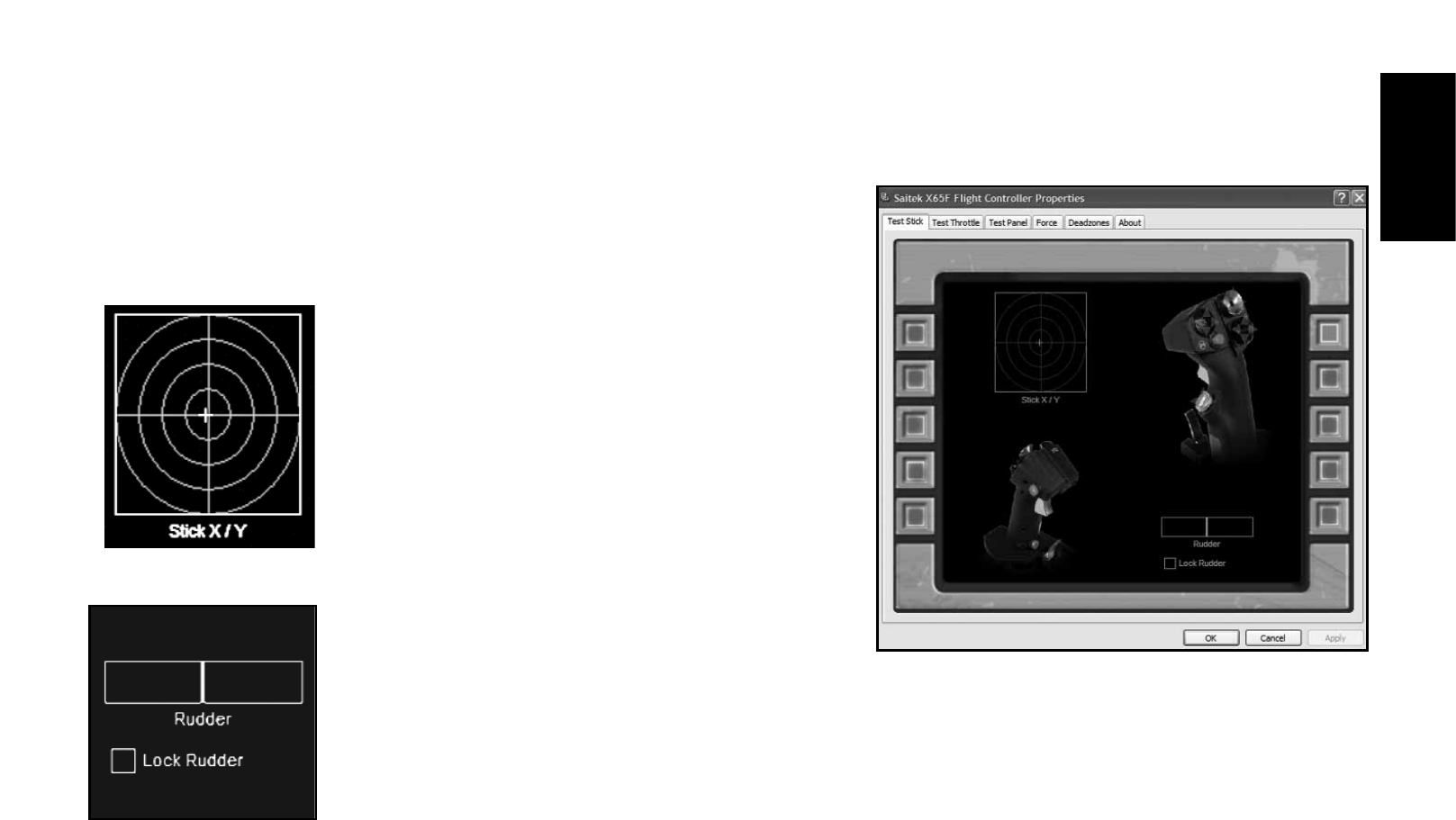
The Pro Flight X65F properties window consists of six separate tabs.
1. Test Stick
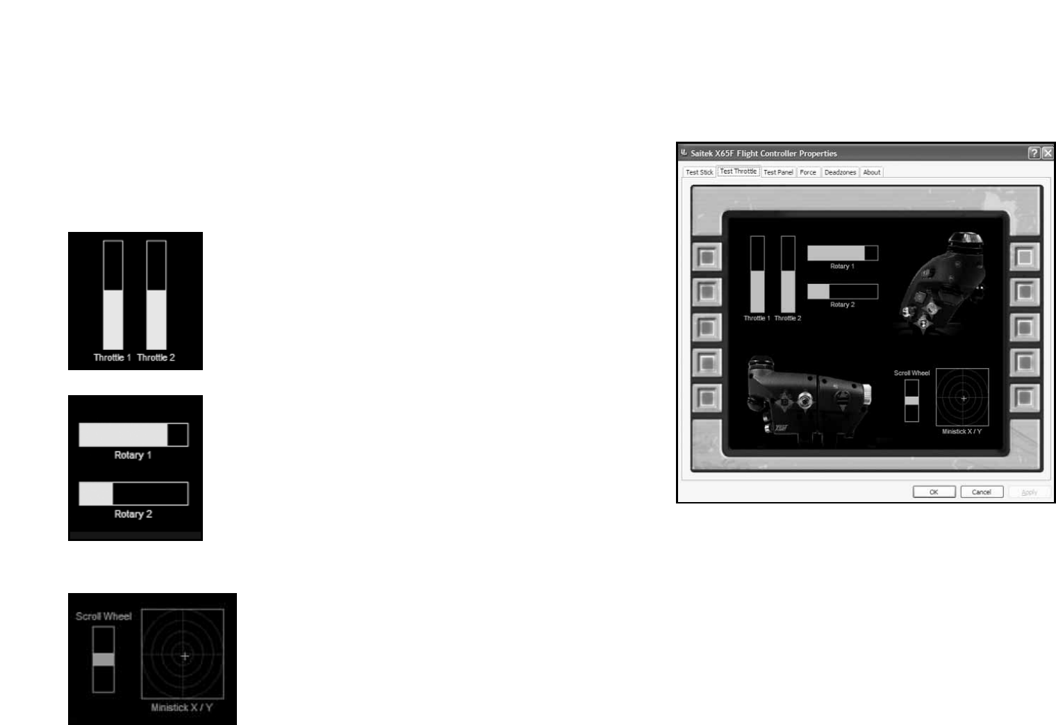
2. Test Throttle
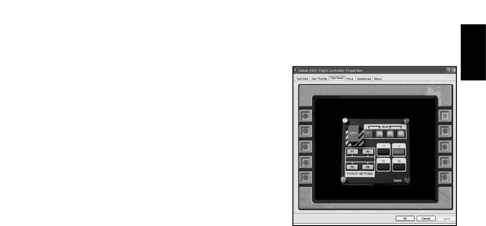
3. Test Panel
4. Force
5. Deadzones
6. About
You can view and change various controller settings in each tab. The settings you can change are described in the following sections.