687345
10
Verklein
Vergroot
Pagina terug
1/100
Pagina verder
SUNNY TRIPO
WER
STP3-6-3AV-40-BE-en-12 | Version 1.2ENGLISH
Operating manual
SUNNY TRIPOWER 3.0 / 4.0 / 5.0 / 6.0
Legal Provisions
SMA Solar Technology AG
Operating manualSTP3-6-3AV-40-BE-en-122
Legal Provisions
The information contained in these documents is the property of SMA Solar Technology AG. No
part of this document may be reproduced, stored in a retrieval system, or transmitted, in any form or
by any means, be it electronic, mechanical, photographic, magnetic or otherwise, without the prior
written permission of SMA Solar Technology AG. Internal reproduction used solely for the purpose
of product evaluation or other proper use is allowed and does not require prior approval.
SMA Solar Technology AG makes no representations or warranties, express or implied, with
respect to this documentation or any of the equipment and/or software it may describe, including
(with no limitation) any implied warranties of utility, merchantability, or fitness for any particular
purpose. All such representations or warranties are expressly disclaimed. Neither SMA Solar
Technology AG nor its distributors or dealers shall be liable for any indirect, incidental, or
consequential damages under any circumstances.
The exclusion of implied warranties may not apply in all cases under some statutes, and thus the
above exclusion may not apply.
Specifications are subject to change without notice. Every attempt has been made to make this
document complete, accurate and up-to-date. Readers are cautioned, however, that product
improvements and field usage experience may cause SMA Solar Technology AG to make changes
to these specifications without advance notice, or per contract provisions in those cases where a
supply agreement requires advance notice. SMA Solar Technology AG shall not be responsible for
any damages, including indirect, incidental or consequential damages, caused by reliance on the
material presented, including, but not limited to, omissions, typographical errors, arithmetical errors
or listing errors in the content material.
SMA Warranty
You can download the current warranty conditions from the Internet at www.SMA-Solar.com.
Software licenses
The licenses for the used software modules can be called up on the user interface of the product.
Trademarks
All trademarks are recognized, even if not explicitly identified as such. Missing designations do not
mean that a product or brand is not a registered trademark.
SMA Solar Technology AG
Sonnenallee 1
34266 Niestetal
Germany
Tel. +49 561 9522-0
Fax +49 561 9522-100
www.SMA.de
Email: info@SMA.de
Status: 9/5/2018
Copyright © 2018 SMA Solar Technology AG. All rights reserved.
Table of Contents
SMA Solar Technology AG
Operating manual STP3-6-3AV-40-BE-en-12 3
Table of Contents
1 Information on this Document................................................. 6
1.1 Validity........................................................................................................................ 6
1.2 Target Group.............................................................................................................. 6
1.3 Content and Structure of this Document ................................................................... 6
1.4 Levels of warning messages...................................................................................... 6
1.5 Symbols in the Document .......................................................................................... 7
1.6 Typographies in the document.................................................................................. 7
1.7 Designation in the document..................................................................................... 7
1.8 Additional Information............................................................................................... 8
2 Safety ........................................................................................ 9
2.1 Intended Use .............................................................................................................. 9
2.2 IMPORTANT SAFETY INSTRUCTIONS.................................................................... 9
3 Scope of Delivery ..................................................................... 12
4 Product Overview .................................................................... 13
4.1 Product Description.................................................................................................... 13
4.2 Symbols on the Product ............................................................................................. 14
4.3 Interfaces and Functions ............................................................................................ 15
4.4 LED Signals................................................................................................................. 16
5 Mounting................................................................................... 18
5.1 Requirements for Mounting ....................................................................................... 18
5.2 Mounting the Inverter................................................................................................. 20
6 Electrical Connection ................................................................ 22
6.1 Overview of the Connection Area............................................................................ 22
6.2 AC Connection........................................................................................................... 22
6.2.1 Requirements for the AC Connection.................................................... 22
6.2.2 Connecting the Inverter to the Utility Grid ............................................ 24
6.2.3 Connecting Additional Grounding........................................................ 25
6.3 Connecting the Network Cables............................................................................... 26
6.4 Connecting RS485 Devices....................................................................................... 28
6.5 Mounting the WLAN Antenna .................................................................................. 29
6.6 DC Connection........................................................................................................... 29
6.6.1 Requirements for the DC Connection.................................................... 29
6.6.2 Assembling the DC Connectors............................................................. 31
6.6.3 Connecting the PV Array........................................................................ 33
6.6.4 Disassembling the DC Connectors ........................................................ 35
Table of Contents
SMA Solar Technology AG
Operating manualSTP3-6-3AV-40-BE-en-124
7 Commissioning ......................................................................... 37
7.1 Commissioning Procedure ......................................................................................... 37
7.2 Commissioning the Inverter........................................................................................ 37
7.3 Selecting a configuration option............................................................................... 39
7.4 Starting the Self-Test (for Italy and Dubai)................................................................ 41
8 Operation ................................................................................. 43
8.1 Establishing a connection to the user interface ........................................................ 43
8.1.1 Establishing a Direct Connection via Ethernet ...................................... 43
8.1.2 Establishing a direct connection via WLAN ......................................... 43
8.1.3 Establishing a Connection via Ethernet in the local network ............... 45
8.1.4 Establishing a Connection via WLAN in the Local Network ............... 46
8.2 Logging In and Out of the User Interface................................................................. 47
8.3 Start Page Design of the User Interface.................................................................... 49
8.4 Activating the Smart Inverter Screen......................................................................... 51
8.5 Starting the Installation Assistant............................................................................... 52
8.6 Activate WPS Function............................................................................................... 53
8.7 Switching WLAN On and Off................................................................................... 53
8.8 Switching the Dynamic Power Display Off............................................................... 54
8.9 Changing the Password............................................................................................. 55
8.10 Changing Operating Parameters.............................................................................. 55
8.11 Configuring the Country Data Set............................................................................. 56
8.12 Configuring Feed-In Management............................................................................ 57
8.13 Configuring the Modbus Function............................................................................. 58
8.14 Activating the Receipt of Control Signals (Only for Italy)........................................ 59
8.15 Deactivating Grounding Conductor Monitoring...................................................... 59
8.16 Setting the Tripping Threshold of the Residual-Current Device................................ 60
8.17 Saving the Configuration in a File............................................................................. 60
8.18 Adopting a Configuration from a File....................................................................... 60
8.19 Updating the Firmware.............................................................................................. 61
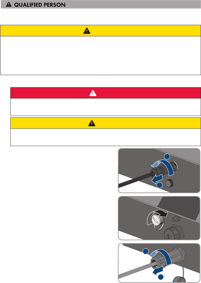
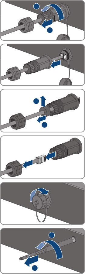
9 Disconnecting the Inverter from Voltage Sources ................. 62
10 Cleaning the Inverter ............................................................... 64
11 Troubleshooting........................................................................ 65
11.1 Forgotten Password.................................................................................................... 65
11.2 Event Messages ......................................................................................................... 66
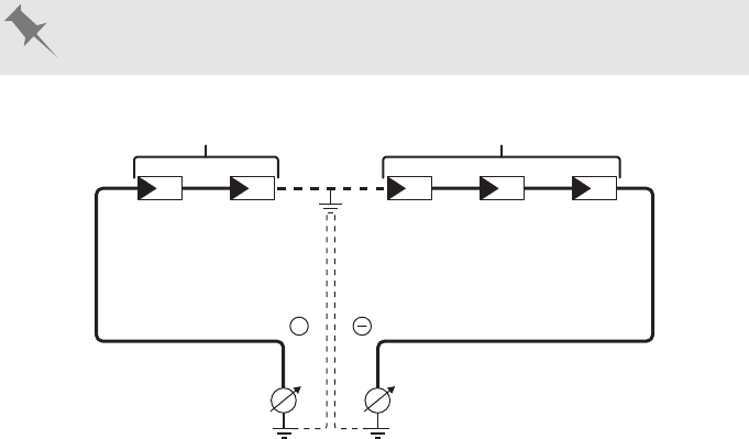
11.3 Checking the PV System for Ground Faults.............................................................. 82
12 Decommissioning the Inverter................................................. 86
Table of Contents
SMA Solar Technology AG
Operating manual STP3-6-3AV-40-BE-en-12 5
13 Technical Data .......................................................................... 89
13.1 DC/AC ....................................................................................................................... 89
13.1.1 Sunny Tripower 3.0 / 4.0...................................................................... 89
13.1.2 Sunny Tripower 5.0 / 6.0...................................................................... 91
13.2 General Data ............................................................................................................. 92
13.3 Climatic Conditions.................................................................................................... 94
13.4 Protective Devices ...................................................................................................... 94
13.5 Equipment................................................................................................................... 94
13.6 Torques ....................................................................................................................... 94
13.7 Data Storage Capacity.............................................................................................. 94
14 Contact ...................................................................................... 96
15 EU Declaration of Conformity ................................................. 98
1 Information on this Document
SMA Solar Technology AG
Operating manualSTP3-6-3AV-40-BE-en-126
1 Information on this Document
1.1 Validity
This document is valid for:
STP3.0-3AV-40 (Sunny Tripower 3.0)
STP4.0-3AV-40 (Sunny Tripower 4.0)
STP5.0-3AV-40 (Sunny Tripower 5.0)
STP6.0-3AV-40 (Sunny Tripower 6.0)
1.2 Target Group
This document is intended for qualified persons and end users. Only qualified persons are allowed
to perform the activities marked in this document with a warning symbol and the caption
"Qualifiedperson". Tasks that do not require any particular qualification are not marked and can
also be performed by end users. Qualified persons must have the following skills:
Knowledge of how an inverter works and is operated
Training in how to deal with the dangers and risks associated with installing, repairing and
using electrical devices and installations
Training in the installation and commissioning of electrical devices and installations
Knowledge of all applicable laws, standards and directives
Knowledge of and compliance with this document and all safety information
1.3 Content and Structure of this Document
This document describes the mounting, installation, commissioning, configuration, operation,
troubleshooting and decommissioning of the product as well as the operation of the product user
interface.
You will find the latest version of this document and further information on the product in PDF format
and as eManual at www.SMA-Solar.com. You can also call up the eManual via the user interface
of the product.
Illustrations in this document are reduced to the essential information and may deviate from the real
product.
1.4 Levels of warning messages
The following levels of warning messages may occur when handling the product.
DANGER
Indicates a hazardous situation which, if not avoided, will result in death or serious injury.
WARNING
Indicates a hazardous situation which, if not avoided, could result in death or serious injury.
1 Information on this Document
SMA Solar Technology AG
Operating manual STP3-6-3AV-40-BE-en-12 7
CAUTION
Indicates a hazardous situation which, if not avoided, could result in minor or moderate injury.
NOTICE
Indicates a situation which, if not avoided, can result in property damage.
1.5 Symbols in the Document
Symbol Explanation
Information that is important for a specific topic or goal, but is not safety-rele-
vant
Indicates a requirement for meeting a specific goal
Desired result
A problem that might occur
Example
Sections describing activities to be performed by qualified persons only
1.6 Typographies in the document
Typography Use Example
bold
Messages
Terminals
Elements on a user interface
Elements to be selected
Elements to be entered
Connect the insulated
conductors to the terminals
X703:1 to X703:6.
Enter 10 in the field
Minutes.
>
Connects several elements to be
selected
Select Settings > Date.
[Button]
[Key]
Button or key to be selected or
pressed
Select [Enter].
1.7 Designation in the document
Complete designation Designation in this document
SunnyTripower Inverter, product
1 Information on this Document
SMA Solar Technology AG
Operating manualSTP3-6-3AV-40-BE-en-128
1.8 Additional Information
For more information, please go to www.SMA-Solar.com.
Title and information content Type of information
"Application for SMAGridGuard Code" Form
"PUBLIC CYBER SECURITY - Guidelines for a Secure PV System
Communication"
Technical information
"Efficiency and Derating"
Efficiency and derating behavior of the SMA inverters
Technical Information
"Parameters and Measured Values"
Overview of all inverter operating parameters and their configura-
tion options
Technical Information
"SMA and SunSpec Modbus® Interface"
Information on the Modbus interface
Technical Information
"Modbus® parameters and measured values"
Device-specific register HTML file
Technical Information
"Temperature Derating" Technical Information
2 Safety
SMA Solar Technology AG
Operating manual STP3-6-3AV-40-BE-en-12 9
2 Safety
2.1 Intended Use
The Sunny Tripower is a transformerless PV inverter which converts the direct current of the PV array
to grid-compliant three-phase current and feeds it into the utility grid.
The product is suitable for indoor and outdoor use.
The product must only be operated with PV modules of protection class II in accordance with
IEC61730, application class A. The PV modules must be compatible with this product.
The product is not equipped with a transformer and therefore has no galvanic isolation. The
product must not be operated with PV modules whose outputs are grounded. This can cause the
product to be destroyed. The product may be operated with PV modules whose frame is grounded.
PV modules with a high capacity to ground must only be used if their coupling capacity does not
exceed 2.25μF (for information on how to calculate the coupling capacity, see the Technical
Information "Leading Leakage Currents" at www.SMA-Solar.com).
All components must remain within their permitted operating ranges and their installation
requirements at all times.
The product must only be used in countries for which it is approved or released by SMA Solar
Technology AG and the grid operator.
Use this product only in accordance with the information provided in the enclosed documentation
and with the locally applicable laws, regulations, standards and directives. Any other application
may cause personal injury or property damage.
Alterations to the product, e.g. changes or modifications, are only permitted with the express written
permission of SMA Solar Technology AG. Unauthorized alterations will void guarantee and
warranty claims and in most cases terminate the operating license. SMA Solar Technology AG
shall not be held liable for any damage caused by such changes.
Any use of the product other than that described in the Intended Use section does not qualify as the
intended use.
The enclosed documentation is an integral part of this product. Keep the documentation in a
convenient place for future reference and observe all instructions contained therein.
This document does not replace and is not intended to replace any local, state, provincial, federal
or national laws, regulations or codes applicable to the installation, electrical safety and use of the
product. SMA Solar Technology AG assumes no responsibility for the compliance or non-
compliance with such laws or codes in connection with the installation of the product.
The type label must remain permanently attached to the product.
2.2 IMPORTANT SAFETY INSTRUCTIONS
SAVE THESE INSTRUCTIONS
This section contains safety information that must be observed at all times when working on or with
the product.
2 Safety
SMA Solar Technology AG
Operating manualSTP3-6-3AV-40-BE-en-1210
The product has been designed and tested in accordance with international safety requirements. As
with all electrical or electronical devices, there are residual risks despite careful construction. To
prevent personal injury and property damage and to ensure long-term operation of the product,
read this section carefully and observe all safety information at all times.
DANGER
Danger to life due to electric shock when live components or cables are
touched
High voltages are present in the conductive components or cables of the product. Touching live
parts and cables results in death or lethal injuries due to electric shock.
Do not touch non-insulated parts or cables.
Disconnect the product from voltage sources and make sure it cannot be reconnected
before working on the device.
After disconnection, wait 5 minutes until the capacitors have discharged.
Do not open the product.
Wear suitable personal protective equipment for all work on the product.
DANGER
Danger to life due to electric shock when live components or DC cables are
touched
When exposed to sunlight, the PV modules generate high DC voltage which is present in the DC
cables. Touching live DC cables results in death or lethal injuries due to electric shock.
Disconnect the product from voltage sources and make sure it cannot be reconnected
before working on the device.
Do not touch non-insulated parts or cables.
Do not disconnect the DC connectors under load.
Wear suitable personal protective equipment for all work on the product.
DANGER
Danger to life due to electric shock from touching an ungrounded PV module
or array frame
Touching ungrounded PV modules or array frames results in death or lethal injuries due to electric
shock.
Connect and ground the frame of the PV modules, the array frame and the electrically
conductive surfaces so that there is continuous conduction. Observe the applicable local
regulations.
2 Safety
SMA Solar Technology AG
Operating manual STP3-6-3AV-40-BE-en-12 11
DANGER
Danger to life due to electric shock when touching live system components in
case of a ground fault
If a ground fault occurs, parts of the system may still be live. Touching live parts and cables
results in death or lethal injuries due to electric shock.
Disconnect the product from voltage sources and make sure it cannot be reconnected
before working on the device.
Touch the cables of the PV array on the insulation only.
Do not touch any parts of the substructure or frame of the PV array.
Do not connect PV strings with ground faults to the inverter.
CAUTION
Risk of burns due to hot enclosure parts
Some parts of the enclosure can get hot during operation.
During operation, do not touch any parts other than the enclosure lid of the inverter.
NOTICE
Damage due to cleaning agents
The use of cleaning agents may cause damage to the product and its components.
Clean the product and all its components only with a cloth moistened with clear water.
3 Scope of Delivery
SMA Solar Technology AG
Operating manualSTP3-6-3AV-40-BE-en-1212
3 Scope of Delivery
Check the scope of delivery for completeness and any externally visible damage. Contact your
distributor if the scope of delivery is incomplete or damaged.
B C
+
D
_
E
F
IH JG
A
Figure 1: Components included in the scope of delivery
Position Quantity Designation
A 1 Inverter
B 1 Wall mounting bracket
C 3 Pan head screw M5x12
D 2 Positive DC connector
E 2 Negative DC connector
F 4 Sealing plug
G 1 AC connector
H 1 RJ45 protective sleeve: swivel nut, cable support sleeve, threaded
sleeve
I 1 WLAN antenna
J 1 Quick reference guide with password label on the rear side
The label contains the following information:
PIC (Product Identification Code) identification key for
registering the system in SunnyPortal
RID (Registration Identifier) registration ID for registering the
system in SunnyPortal
WLAN password WPA2-PSK (WiFi Protected Access 2 -
Preshared Key) for direct connection to the inverter via WLAN
4 Product Overview
SMA Solar Technology AG
Operating manual STP3-6-3AV-40-BE-en-12 13
4 Product Overview
4.1 Product Description
SUNNY BO
Y
B
C
A
Figure 2: Design of the Product
Position Designation
A DC load-break switch
B LEDs
The LEDs indicate the operating state of the inverter.
C Type label
The type label clearly identifies the product. The type label must remain
permanently attached to the product. You will find the following informa-
tion on the type label:
Device type (Model)
Serial number (Serial No. or S/N)
Date of manufacture
Identification key (PIC) for registration in Sunny Portal
Registration ID (RID) for registration in Sunny Portal
WLAN password (WPA2-PSK) for the direct connection to the user
interface of the inverter via WLAN
Device-specific characteristics
4 Product Overview
SMA Solar Technology AG
Operating manualSTP3-6-3AV-40-BE-en-1214
4.2 Symbols on the Product
Symbol Explanation
Beware of a danger zone
This symbol indicates that the product must be additionally grounded if addi-
tional grounding or equipotential bonding is required at the installation site.
Beware of electrical voltage
The product operates at high voltages.
Beware of hot surface
The product can get hot during operation.
5 min
Danger to life due to high voltages in the inverter; observe a waiting time of 5
minutes
High voltages that can cause lethal electric shocks are present in the live com-
ponents of the inverter.
Prior to performing any work on the inverter, disconnect it from all voltage
sources as described in this document.
Observe the documentation
Observe all documentation supplied with the product.
Observe the documentation
Together with the red LED, this symbol indicates an error.
Inverter
Together with the green LED, this symbol indicates the operating state of the in-
verter.
Data transmission
Together with the blue LED, this symbol indicates the status of the network con-
nection.
Grounding conductor
This symbol indicates the position for connecting a grounding conductor.
Three-phase alternating current with neutral conductor
WEEE designation
Do not dispose of the product together with the household waste but in accor-
dance with the disposal regulations for electronic waste applicable at the in-
stallation site.
4 Product Overview
SMA Solar Technology AG
Operating manual STP3-6-3AV-40-BE-en-12 15
Symbol Explanation
CE marking
The product complies with the requirements of the applicable EU directives.
RCM (Regulatory Compliance Mark)
The product complies with the requirements of the applicable Australian stan-
dards.
4.3 Interfaces and Functions
The inverter is equipped with the following interfaces and functions:
User interface for monitoring and configuration
The product is equipped as standard with an integrated webserver, which provides a user interface
for configuring and monitoring the product. The product user interface can be called up via the web
browser if there is an existing connection to an end device (e.g. computer, tablet PC or
smartphone).
Smart Inverter Screen
The Smart Inverter Screen enables you to view the status display and to display the current power
and consumption on the user interface login page. You therefore have an overview of the most
important inverter data without having to log into the user interface.
The Smart Inverter Screen is deactivated by default. The Smart Inverter Screen can be activated via
the user interface once the inverter has been commissioned.
SMA Speedwire
The product is equipped with SMASpeedwire as standard. SMASpeedwire is a type of
communication based on the Ethernet standard. SMASpeedwire is designed for a data transfer
rate of 100Mbps and enables optimum communication between Speedwire devices within
systems.
SMA Webconnect
The inverter is equipped with a Webconnect function as standard. The Webconnect function
enables direct data transmission between the inverters of a small-scale plant and the Internet portals
SunnyPortal and SunnyPlaces without any additional communication device and for a maximum
of 4 inverters per visualized system. In large-scale PV power plants with more than 4 inverters, there
is the option of establishing data transmission between the inverters and the web-based monitoring
platform SunnyPortal and SunnyPlaces via the data logger (e.g. SMADataManager) or to
distribute the inverters over several plants. You can directly access your visualized system via the
web browser on your end device.
WLAN
The product is equipped with a WLAN interface as standard. The inverter is delivered with the
WLAN interface activated as standard. If you do not want to use WLAN, you can deactivate the
WLAN interface.
4 Product Overview
SMA Solar Technology AG
Operating manualSTP3-6-3AV-40-BE-en-1216
Modbus
The product is equipped with a Modbus interface. The Modbus interface is deactivated by default
and must be configured as needed.
The Modbus interface of the supported SMA products is designed for industrial use – via SCADA
systems, for example – and has the following tasks:
Remote query of measured values
Remote setting of operating parameters
Setpoint specifications for system control
Grid management services
The product is equipped with service functions for grid management.
Depending on the requirements of the grid operator, you can activate and configure the functions
(e.g. active power limitation) via operating parameters.
Parallel Operation of the DC Inputs A and B
You have the option of operating the inverter DC inputs A and B in parallel. As a result, and as
opposed to normal operation, several parallel-connected strings can be connected to the inverter.
The inverter automatically detects the parallel operation of the DC inputs A and B.
SMAOptiTracGlobalPeak
SMAOptiTracGlobalPeak is an advancement of SMAOptiTrac and allows the operating point of
the inverter to follow the optimal operating point of the PV array (MPP) precisely at all times. In
addition, with the aid of SMAOptiTracGlobalPeak, the inverter detects several maximum power
points in the available operating range, such as may occur particularly with partially shaded
strings. SMA OptiTrac Global Peak is enabled by default.
All-pole sensitive residual-current monitoring unit
The all-pole sensitive residual-current monitoring unit detects alternating and direct differential
currents. In single-phase and three-phase inverters, the integrated differential current sensor detects
the current difference between the neutral conductor and the line conductor(s). If the current
difference increases suddenly, the inverter disconnects from the utility grid.
SMA Smart Connected
SMA Smart Connected is the free monitoring of the inverter via the SMA SunnyPortal. Thanks to
SMA Smart Connected, the PV system operator and qualified person will be informed automatically
and proactively about inverter events that occur.
SMA Smart Connected is activated during registration in SunnyPortal. In order to use SMA Smart
Connected, it is necessary that the inverter is permanently connected to SunnyPortal and the data
of the PV system operator and qualified person is stored in SunnyPortal and up-to-date.
4.4 LED Signals
The LEDs indicate the operating state of the inverter.
4 Product Overview
SMA Solar Technology AG
Operating manual STP3-6-3AV-40-BE-en-12 17
LED signal Explanation
The green LED is flashing
(twoseconds on and
twoseconds off)
Waiting for feed-in conditions
The conditions for feed-in operation are not yet met. As soon as the
conditions are met, the inverter will start feed-in operation.
The green LED flashes
quickly
Update of central processing unit
The central processing unit of the inverter is being updated.
The green LED is glowing Feed-in operation
The inverter feeds in with a power of at least 90%.
The green LED is pulsing Feed-in operation
The inverter is equipped with a dynamic power display via the green
LED. Depending on the power, the green LED pulses fast or slow. If
necessary, you can switch off the dynamic power display via the
green LED.
The green LED is off The inverter is not feeding into the utility grid.
The red LED is glowing Event occurred
If an event occurs, a distinct event message and the corresponding
event number will be displayed in addition on the inverter user inter-
face or in the communication product.
The blue LED flashes slowly
for approx. one minute
Communication connection is being established
The inverter is establishing a connection to a local network or is es-
tablishing a direct connection to an end device via Ethernet (e.g.
computer, tablet PC or smartphone).
The blue LED flashes quickly
for approx. two minutes.
WPS active
The WPS function is active.
The blue LED is glowing Communication active
There is an active connection with a local network or there is a di-
rect connection with an end device via Ethernet (e.g. computer,
tablet PC or smartphone).
5 Mounting
SMA Solar Technology AG
Operating manualSTP3-6-3AV-40-BE-en-1218
5 Mounting
5.1 Requirements for Mounting
Requirements for the Mounting Location:
WARNING
Danger to life due to fire or explosion
Despite careful construction, electrical devices can cause fires.
Do not mount the product in areas containing highly flammable materials or gases.
Do not mount the product in potentially explosive atmospheres.
A solid support surface must be available (e.g., concrete or masonry). When mounted on
drywall or similar materials, the product emits audible vibrations during operation which could
be perceived as annoying.
The mounting location must be inaccessible to children.
The mounting location must be suitable for the weight and dimensions of the product (see
Section13 "Technical Data", page89).
The mounting location must not be exposed to direct solar irradiation. If the product is
exposed to direct solar irradiation, the exterior plastic parts might age prematurely and
overheating might occur. When becoming too hot, the product reduces its power output to
avoid overheating.
The mounting location should be freely and safely accessible at all times without the need for
any auxiliary equipment (such as scaffolding or lifting platforms). Non-fulfillment of these
criteria may restrict servicing.
All ambient conditions must be met (see Section13, page89).
To ensure optimum operation, the ambient temperature should be between -25°C and
+40°C.
Permitted and prohibited mounting positions:
The product may only be mounted in a permitted position. This will ensure that no moisture can
penetrate the product.
The product should be mounted such that the LED signals can be read off without difficulty.
15°
Figure 3: Permitted and prohibited mounting positions
5 Mounting
SMA Solar Technology AG
Operating manual STP3-6-3AV-40-BE-en-12 19
Dimensions for mounting:
UP
90
120
150
30
172
298
470
121
9 x 18
Ø 9
9 x 18
315
435
9 x 18
107.5
126.5
93
156.5 156.5
217.5 217.5
Figure 4: Position of the anchoring points(Dimensions in mm)
Recommended clearances:
If you maintain the recommended clearances, adequate heat dissipation will be ensured. Thus, you
will prevent power reduction due to excessive temperature.
Maintain the recommended clearances to walls as well as to other inverters or objects.
If multiple inverters are mounted in areas with high ambient temperatures, increase the
clearances between the inverters and ensure sufficient fresh-air supply.
5 Mounting
SMA Solar Technology AG
Operating manualSTP3-6-3AV-40-BE-en-1220
210 270 210
100
430430430
450450450
450450450
430430430
150
Figure 5: Recommended clearances(Dimensions in mm)
5.2 Mounting the Inverter
Additionally required mounting material (not included in the scope of delivery):
3 screws, suitable for the support surface and the weight of the inverter (diameter: minimum
6mm)
3 washers, suitable for the screws (outer diameter: minimum 18mm)
Where necessary, 3 screw anchors suitable for the support surface and the screws
CAUTION
Risk of injury due to weight of product
Injuries may result if the product is lifted incorrectly or dropped while being transported or when
attaching it to or removing it from the wall mounting bracket.
Transport and lift the product carefully. Take the weight of the product into account.
Wear suitable personal protective equipment for all work on the product.
Procedure:
1.
CAUTION
Risk of injury due to damaged cables
There may be power cables or other supply lines (e.g. gas or water) routed in the wall.
Ensure that no lines are laid in the wall which could be damaged when drilling holes.
5 Mounting
SMA Solar Technology AG
Operating manual STP3-6-3AV-40-BE-en-12 21
2. Align the wall mounting bracket horizontally on the
wall and mark the position of the drill holes. Use at
least one hole on the right- and left-hand side and
the lower hole in the middle of the wall mounting
bracket. Tip: When mounting on a post, use the
upper and lower central holes of the wall mounting
bracket.
UP
3. Set the wall mounting bracket aside and drill the marked holes.
4. Insert screw anchors into the drill holes if the support surface requires them.
5. Secure the wall mounting bracket horizontally using
screws and washers.
UP
6. Hook the inverter into the wall mounting bracket.
When doing so, the two right- and left-hand keys on
the ribs on the rear side of the inverter must be
hooked into the respective right-hand and left-hand
keyways in the wall mounting bracket.
7. Ensure that the inverter is securely in place.
8. Secure the inverter to the wall mounting bracket. To
do so, insert one pan head screw M5x12 each into
the lower screw hole on both sides of the inverter
anchorage bracket respectively and tighten them
using a Torx screwdriver (TX25, torque: 2.5Nm).
6 Electrical Connection
SMA Solar Technology AG
Operating manualSTP3-6-3AV-40-BE-en-1222
6 Electrical Connection
6.1 Overview of the Connection Area
RS485
A
B
+
+
AC
F
A
C
B ED
G
Figure 6: Connection areas at the bottom of the inverter
Position Designation
A One positive and one negative DC connector, input A
B One positive and one negative DC connector, input B
C Jack with protective cap for RS485 communication connection
D Network port with protective cap
E Jack with protective cap for the WLAN antenna
F Jack for the AC connection
G Connection point for an additional grounding
6.2 AC Connection
6.2.1 Requirements for the AC Connection
Cable requirements:
External diameter: 8mm to 21mm
Conductor cross-section: 1.5mm² to 6mm²
Insulation stripping length: 12mm
Sheath stripping length: 50mm
The cable must be dimensioned in accordance with the local and national directives for the
dimensioning of cables. The requirements for the minimum wire size derive from these
directives. Examples of factors influencing cable dimensioning are: nominal AC current, type of
cable, routing method, cable bundling, ambient temperature and maximum desired line losses
(for calculation of line losses, see the design software "SunnyDesign" from software
version2.0 at www.SMA-Solar.com).
6 Electrical Connection
SMA Solar Technology AG
Operating manual STP3-6-3AV-40-BE-en-12 23
Load-break switch and cable protection:
NOTICE
Damage to the inverter due to the use of screw-type fuses as load-break
switches
Screw-type fuses (e.g. DIAZED fuse or NEOZED fuse) are not load-break switches.
Do not use screw-type fuses as load-break switches.
Use a load-break switch or circuit breaker as a load disconnection unit (for information and
design examples, see the Technical Information "Circuit Breaker" at www.SMA-Solar.com).
In PV systems with multiple inverters, protect each inverter with a separate circuit breaker.
Make sure to observe the maximum permissible fuse protection (see Section13 "Technical
Data", page89). This will prevent residual voltage being present at the corresponding cable
after disconnection.
Loads installed between the inverter and the circuit breaker must be fused separately.
Residual-current monitoring unit:
If an external residual-current device is required, install a residual-current device which trips at
a residual current of 100mA or higher (for details on selecting a residual-current device, see
the Technical Information "Criteria for Selecting a Residual-Current Device" at www.SMA-
Solar.com).
If a residual-current device with a tripping threshold of 30mA is required and used, you must
set the tripping threshold of the residual-current device in the inverter to 30mA (see
Section8.16, page60).
Overvoltage category:
The inverter can be used in grids of overvoltage categoryIII or lower in accordance with
IEC60664-1. That means that the inverter can be permanently connected to the grid-connection
point of a building. In case of installations with long outdoor cabling routes, additional measures to
reduce overvoltage categoryIV to overvoltage categoryIII are required (see the Technical
Information "Overvoltage Protection" at www.SMA-Solar.com).
Grounding conductor monitoring:
The inverter is equipped with a grounding conductor monitoring device. This grounding conductor
monitoring device detects when there is no grounding conductor connected and disconnects the
inverter from the utility grid if this is the case. Depending on the installation site and grid
configuration, it may be advisable to deactivate the grounding conductor monitoring. This is
necessary, for example, in an IT system if there is no neutral conductor present and you intend to
install the inverter between two line conductors. If you are uncertain about this, contact your grid
operator or SMA Solar Technology AG.
Grounding conductor monitoring must be deactivated after initial start-up depending on the
grid configuration (see Section8.15, page59).
6 Electrical Connection
SMA Solar Technology AG
Operating manualSTP3-6-3AV-40-BE-en-1224
Safety in accordance with IEC62109 when the grounding conductor
monitoring is deactivated
In order to guarantee safety in accordance with IEC62109 when the grounding conductor
monitoring is deactivated, you have to connect an additional grounding conductor to the
inverter.
Connect an additional grounding conductor that has an cross-section of at least 10mm
(see Section6.2.3, page25). This prevents touch current in the event of the grounding
conductor on the AC connector bush insert failing.
Connection of an additional grounding conductor
In some countries, an additional grounding conductor is generally required. In each case,
observe the locally applicable regulations.
If an additional grounding conductor is required, connect the one that has an cross-
section of at least 10mm (see Section6.2.3, page25). This prevents touch current in
the event of the grounding conductor on the AC connector bush insert failing.
6.2.2 Connecting the Inverter to the Utility Grid
Requirements:
The connection requirements of the grid operator must be met.
The grid voltage must be within the permissible range. The exact operating range of the
inverter is specified in the operating parameters.
Procedure:
1. Disconnect the circuit breaker and secure it against reconnection.
2. Dismantle the AC cable by 50mm.
3. Shorten L1, L2, L3 and N by 8mm each so that the grounding conductor is 8mm longer. This
ensures that the grounding conductor is the last to be pulled from the screw terminal in the
event of tensile strain.
4. Strip the insulation of L1, L2, L3, N and the grounding conductor by 12mm.
5. In the case of fine stranded wire, L1, L2, L3, N and the grounding conductor are to be fitted
with bootlace ferrules.
6. Assemble the AC connector and connect the conductor to the AC connector (see manual of
the AC connector).
7. Ensure that all conductors are securely connected to the AC connector.
8. Plug the AC connector into the jack for the AC
connection. When doing so, align the AC connector
so that the key on the inverter AC jack is inserted
into the keyway on the AC connector bush insert.
6 Electrical Connection
SMA Solar Technology AG
Operating manual STP3-6-3AV-40-BE-en-12 25
6.2.3 Connecting Additional Grounding
If additional grounding or equipotential bonding is required locally, you can connect additional
grounding to the inverter. This prevents touch current if the grounding conductor on the AC
connector fails. The necessary ring terminal lug and the screw are included in the scope of delivery
of the inverter.
Additionally required material (not included in the scope of delivery):
1 grounding cable
Cable requirement:
Use of fine-stranded conductors
You can use an inflexible or a flexible, fine-stranded conductor.
When using a fine-stranded conductor, it has to be double crimped by a ring terminal lug.
Make sure that no insulated conductor is visible when pulling or bending. This will ensure
sufficient strain relief by means of the ring terminal lug.
Grounding cable cross-section: max. 10mm²
Procedure:
1. Strip the grounding cable insulation.
2. Insert the stripped part of the grounding cable into the ring terminal lug and crimp using a
crimping tool.
3. Insert the pan head screw M5x12 into the screw
hole in the ring terminal lug and screw the ring
terminal lug with screw firmly onto the connection
point for additional grounding using a Torx
screwdriver (TX25, torque: 2.5Nm).
6 Electrical Connection
SMA Solar Technology AG
Operating manualSTP3-6-3AV-40-BE-en-1226
6.3 Connecting the Network Cables
DANGER
Danger to life due to electric shock in case of overvoltages and if surge
protection is missing
Overvoltages (e.g. in the event of a flash of lightning) can be further conducted into the building
and to other connected devices in the same network via the network cables or other data cables
if there is no surge protection. Touching live parts and cables results in death or lethal injuries due
to electric shock.
Ensure that all devices in the same network are integrated in the existing overvoltage
protection.
When laying the network cable outdoors, ensure that there is suitable surge protection at
the network cable transition from the product outdoors to the network inside the building.
The Ethernet interface of the inverter is classified as "TNV-1" and offers protection against
overvoltages of up to 1.5kV.
Additionally required material (not included in the scope of delivery):
1 network cable
Cable requirements:
The cable length and quality affect the quality of the signal. Observe the following cable
requirements.
Cable type: 100BaseTx
Cable category: Cat5, Cat5e, Cat6, Cat6a or Cat7
Plug type: RJ45 of Cat5, Cat5e, Cat6 or Cat6a
Shielding: SF/UTP, S/UTP, SF/FTP or S/FTP
Number of insulated conductor pairs and insulated conductor cross-section: at least 2 x 2 x
0.22 mm²
Maximum cable length between two nodes when using patch cables: 50m
Maximum cable length between two nodes when using installation cables: 100m
UV-resistant for outdoor use
NOTICE
Damage to the inverter due to moisture ingress
Moisture penetration can damage the inverter and impair its functionality.
Connect the network cable with the supplied RJ45 protective sleeve to the inverter.
6 Electrical Connection
SMA Solar Technology AG
Operating manual STP3-6-3AV-40-BE-en-12 27
Procedure:
1.
DANGER
Danger to life due to electric shock
Disconnect the inverter from all voltage sources (see Section9, page62).
2. Unscrew the protective cap from the network port.
3. Press the cable support sleeve out of the threaded sleeve.
4. Thread the swivel nut and threaded sleeve over the
network cable. At the same time, thread the network
cable through the opening in the cable support
sleeve.
1
2
5. Press the cable support sleeve into the threaded
sleeve.
6. Plug the network cable connector into the network
port on the inverter and screw the threaded sleeve
onto the network port thread on the inverter.
3
1
2
7. Screw the swivel nut onto the threaded sleeve.
1
2
6 Electrical Connection
SMA Solar Technology AG
Operating manualSTP3-6-3AV-40-BE-en-1228
8. If you would like to establish a direct connection, connect the other end of the network cable
directly to the end device.
9. If you would like to integrate the inverter into a local network, connect the other end of the
network cable to the local network (e.g. via a router).
6.4 Connecting RS485 Devices
Additionally required material (not included in the scope of delivery):
One communication cable for RS485 communication
One M12 plug, 4-pole
Signal assignment:
Pin connector Signal TS4 Gateway Insulated con-
ductor color
4 3
1 2
1 GND -
2 +12 V +
3 Data- B
4 Data+ A
Procedure:
1.
DANGER
Danger to life due to electric shock
Disconnect the inverter from all voltage sources (see Section9, page62).
2. Assemble the M12 plug and connect the RS485 cable to the plug (see manual of the M12
connector).
3. Ensure that all conductors are correctly connected to the M12 plug.
4. Unscrew the protective cap from the jack for the
RS485 communication connection.
RS485
6 Electrical Connection
SMA Solar Technology AG
Operating manual STP3-6-3AV-40-BE-en-12 29
5. Plug the M12 connector into the jack for the RS485
communication connection and screw tight. When
doing so, align the connector so that the key on the
inverter AC jack is inserted into the keyway on the
plug.
RS485
1
2
6.5 Mounting the WLAN Antenna
Requirement:
The WLAN antenna supplied must be used.
Procedure:
1.
DANGER
Danger to life due to electric shock
Disconnect the inverter from all voltage sources (see Section9, page62).
2. Remove the protective cap from the jack on the inverter.
3. Plug the WLAN antenna into the jack and screw
tight (torque: 1Nm).
1
2
4. Pull on the WLAN antenna to ensure that the WLAN antenna is securely in place.
6.6 DC Connection
6.6.1 Requirements for the DC Connection
Connection options:
The inverter has two DC inputs, to each of which one string can be connected in normal operation.
6 Electrical Connection
SMA Solar Technology AG
Operating manualSTP3-6-3AV-40-BE-en-1230
You have the option of operating the DC inputs A and B in parallel, and therefore of connecting
several strings to the inverter.
RS485
A
B
+
+
AC
+
A
B
+
+
_
+
_
Figure 7: Connection overview for normal operation
RS485
A
B
+
+
AC
+
A
B
+
+
_
+
_
+
_
Figure 8: Connection overview for parallel connection of the DC inputs A and B
Requirements for the PV modules per input:
All PV modules must be of the same type.
All PV modules must be aligned and tilted identically.
On the coldest day based on statistical records, the open-circuit voltage of the PV array must
never exceed the maximum input voltage of the inverter.
The maximum input current per string must be maintained and must not exceed the through-
fault current of the DC connectors (see Section13 "Technical Data", page89).
6 Electrical Connection
SMA Solar Technology AG
Operating manual STP3-6-3AV-40-BE-en-12 31
The thresholds for the input voltage and the input current of the inverter must be adhered to
(see Section13 "Technical Data", page89).
The positive connection cables of the PV modules must be equipped with positive DC
connectors (see Section6.6.2, page31).
The negative connection cables of the PV modules must be equipped with the negative DC
connectors (see Section6.6.2, page31).
Use of Y adapters for parallel connection of strings
The Y adapters must not be used to interrupt the DC circuit.
Do not use the Y adapters in the immediate vicinity of the inverter. The adapters must not
be visible or freely accessible.
In order to interrupt the DC circuit, always disconnect the inverter as described in this
document (see Section9, page62).
6.6.2 Assembling the DC Connectors
For connection to the inverter, all PV module connection cables must be fitted with the DC
connectors provided. Assemble the DC connectors as described in the following. Be sure to observe
the correct polarity. The DC connectors are marked with the symbols "+" and "-".
Figure 9: Negative (A) and positive (B) DC connectors
Cable requirements:
Cable type: PV1-F, UL-ZKLA, USE2
External diameter: 5mmto8mm
Conductor cross-section: 2.5mm²to6mm²
Qty single wires: minimum7
Nominal voltage: minimum 1000V
Using bootlace ferrules is not allowed.
DANGER
Danger to life due to high voltages on the DC conductors
When exposed to sunlight, the PV array generates dangerous DC voltage which is present in the
DC conductors. Touching the DC conductors can lead to lethal electric shocks.
Ensure that the inverter is disconnected from all voltage sources.
Do not touch non-insulated cable ends.
Do not touch the DC conductors.
6 Electrical Connection
SMA Solar Technology AG
Operating manualSTP3-6-3AV-40-BE-en-1232
NOTICE
Destruction of the inverter due to overvoltage
If the open-circuit voltage of the PV modules exceeds the maximum input voltage of the inverter,
the inverter can be destroyed due to overvoltage.
If the open-circuit voltage of the PV modules exceeds the maximum input voltage of the
inverter, do not connect any strings to the inverter and check the design of the PV system.
Procedure:
1. Strip 12mm of the cable insulation.
2. Insert the stripped cable into the DC connector up to
the stop. When doing so, ensure that the stripped
cable and the DC connector are of the same
polarity.
+
3. Press the clamping bracket down until it audibly
snaps into place.
+
The stranded wire can be seen inside the
clamping bracket chamber.
+
The stranded wire cannot be seen in the chamber?
The cable is not correctly in place.
Release the clamping bracket. To do so,
insert a screwdriver (blade width: 3.5mm)
into the clamping bracket and pry the
clamping bracket open.
2
+
1
6 Electrical Connection
SMA Solar Technology AG
Operating manual STP3-6-3AV-40-BE-en-12 33
Remove the cable and go back to step2.
4. Push the swivel nut up to the thread and tighten
(torque: 2Nm).
+
1
2
6.6.3 Connecting the PV Array
NOTICE
Destruction of the inverter due to overvoltage
If the open-circuit voltage of the PV modules exceeds the maximum input voltage of the inverter,
the inverter can be destroyed due to overvoltage.
If the open-circuit voltage of the PV modules exceeds the maximum input voltage of the
inverter, do not connect any strings to the inverter and check the design of the PV system.
NOTICE
Destruction of the measuring device due to overvoltage
Only use measuring devices with a DC input voltage range of 1000V or higher.
NOTICE
Damage to the DC connectors due to the use of contact cleaner of other
cleaning agents
Some contact cleaners or other cleaning agents may contain substances that decompose the
plastic of the DC connectors.
Do not use contact cleaners or other cleaning agents for cleaning the DC connectors.
NOTICE
Damage to the inverter due to ground fault on DC side during operation
Due to the transformerless topology of the product, the occurance of ground faults on DC side
during operation can lead to irreparable damage. Damages to the product due to a faulty or
damaged DC installation are not covered by warranty. The product is equipped with a protective
device that checks whether a ground fault is present during the starting sequence. The product is
not protected during operation.
Ensure that the DC installation is carried out correctly and no ground fault occurs during
operation.
Procedure:
1. Ensure that the circuit breaker is switched off and that it cannot be reconnected.
6 Electrical Connection
SMA Solar Technology AG
Operating manualSTP3-6-3AV-40-BE-en-1234
2. If an external DC load-break switch is installed, disconnect the external DC load-break switch
from all voltage sources.
3. Set the DC load-break switch of the inverter to
position O.
4. Measure the PV array voltage. Ensure that the maximum input voltage of the inverter is
adhered to and that there is no ground fault in the PV array.
5. Check whether the DC connectors have the correct polarity.
If the DC connector is equipped with a DC cable of the wrong polarity, the DC connector must
be reassembled. The DC cable must always have the same polarity as the DC connector.
6. Ensure that the open-circuit voltage of the PV array does not exceed the maximum input
voltage of the inverter.
7. Connect the assembled DC connectors to the
inverter.
+
+
_
The DC connectors snap into place.
8. Ensure that all DC connectors are securely in place.
9.
NOTICE
Damage to the product due to sand, dust and moisture ingress if the DC
inputs are not closed
The product is only properly sealed when all unused DC inputs are closed with DC
connectors and sealing plugs. Sand, dust and moisture penetration can damage the product
and impair its functionality.
Seal all unused DC inputs using the DC connectors and sealing plugs as described in
the following. When doing so, do not plug the sealing plugs directly into the DC inputs
on the inverter.
10. For unused DC connectors, push down the clamping bracket and push the swivel nut up to the
thread.
6 Electrical Connection
SMA Solar Technology AG
Operating manual STP3-6-3AV-40-BE-en-12 35
11. Insert the sealing plug into the DC connector.
+
12. Insert the DC connectors with sealing plugs into the
corresponding DC inputs on the inverter.
+
+
_
The DC connectors snap into place.
13. Ensure that the DC connectors with sealing plugs are securely in place.
6.6.4 Disassembling the DC Connectors
To disassemble the DC connectors (e.g. due to faulty assembly), proceed as follows.
Procedure:
DANGER
Danger to life due to electric shock when touching exposed DC conductors or
DC plug contacts if the DC connectors are damaged or loose
The DC connectors can break or become damaged, become free of the DC cables, or no longer
be connected correctly if the DC connectors are released and disconnected incorrectly. This can
result in the DC conductors or DC plug contacts being exposed. Touching live DC conductors or
DC plug connectors will result in death or serious injury due to electric shock.
Wear insulated gloves and use insulated tools when working on the DC connectors.
Ensure that the DC connectors are in perfect condition and that none of the DC conductors
or DC plug contacts are exposed.
Carefully release and remove the DC connectors as described in the following.
1. Release and remove the DC connectors. To do so,
insert a flat-blade screwdriver or an angled
screwdriver (blade width: 3.5mm) into one of the
side slots and pull the DC connectors out. When
doing so, do not lever the DC connectors out, but
insert the tool into one of the side slots only to
release the locking mechanism, and do not pull on
the cable.
2
1
6 Electrical Connection
SMA Solar Technology AG
Operating manualSTP3-6-3AV-40-BE-en-1236
2. Remove the DC connector swivel nut.
+
3. Unlock the DC connector. To do this, insert a flat-
blade screwdriver (blade width: 3.5mm) into the
side catch mechanism and pry the catch mechanism
open.
+
2
3
1
4. Carefully pull the DC connector apart.
5. Release the clamping bracket. To do so, insert a flat-
blade screwdriver (blade width: 3.5mm) into the
clamping bracket and pry the clamping bracket
open.
2
+
1
6. Remove the cable.
7 Commissioning
SMA Solar Technology AG
Operating manual STP3-6-3AV-40-BE-en-12 37
7 Commissioning
7.1 Commissioning Procedure
This section describes the commissioning procedure and gives an overview of the steps you must
perform in the prescribed order.
Procedure See
1. Commission the inverter. Section7.2, page37
2. Establish a connection to the user interface of the inverter.
There are various connection options to choose from for
this:
Direct connection via WLAN
Direct connection via Ethernet
Connection via WLAN in the local network
Connection via Ethernet in the local network
Section8.1, page43
3. Log into the user interface. Section8.2, page47
4. Select the inverter configuration option. Please note that
the SMAGridGuard code for changing the grid-relevant
parameters must be available after completion of the first
ten feed-in hours or installation assistant (see "Application
for the SMAGridGuard code" available at www.SMA-
Solar.com).
Section7.3, page39
5. Ensure that the country data set has been configured cor-
rectly.
Section8.11, page56
6. For PV systems in Italy or Dubai: Start the self-test. Section7.4, page41
7. Make further inverter settings as needed. Section8, page43
7.2 Commissioning the Inverter
Requirements:
The AC circuit breaker must be correctly rated and mounted.
The inverter must be correctly mounted.
All cables must be correctly connected.
Procedure:
1. Switch on the AC circuit breaker.
7 Commissioning
SMA Solar Technology AG
Operating manualSTP3-6-3AV-40-BE-en-1238
2. Turn the DC load-break switch of the inverter to
position I.
All three LEDs light up. The start-up phase begins.
All three LEDs go out again after approximately 90seconds.
The green LED starts to flash and, if the inverter is connected via Speedwire, the blue LED also
starts to flash.
The green LED is still flashing?
The conditions for activating feed-in operation are not yet met.
As soon as the conditions for feed-in operation are met, the inverter starts with feed-in
operation and, depending on the available power, the green LED will light up
continuously or it will pulse.
The red LED is glowing?
An error has occurred.
Rectify the error (see Section11, page65).
7 Commissioning
SMA Solar Technology AG
Operating manual STP3-6-3AV-40-BE-en-12 39
7.3 Selecting a configuration option
After you have logged onto the user interface as Installer, the Configuring the Inverter page
opens.
A
E
B
D
C
Figure 10: Layout of the Configuring the Inverter page
Position Designation Description
A Device information Provides the following information:
Device name
Inverter serial number
Inverter firmware version
B User information Provides brief information on the listed configuration
options
C Skip configuration Offers the option of skipping the inverter configura-
tion and go directly to the user interface (not recom-
mended)
D Checkbox Allows you to choose not to have the displayed page
displayed again when the user interface is called up
again
E Configuration options Provides a selection of the various configuration op-
tions
Procedure:
On the Configuring the Inverter page, different configuration options are available to choose
from. Select one of the options and proceed for the selected option as described below. SMA
Solar Technology AG recommends carrying out the configuration with the installation assistant. This
way, you ensure that all relevant parameters are set for optimal inverter operation.
7 Commissioning
SMA Solar Technology AG
Operating manualSTP3-6-3AV-40-BE-en-1240
Adoption of configuration from a file
Configuration with the installation assistant (recommended)
Manual configuration
Accepting the settings
Saving the made settings is indicated by an hourglass symbol on the user interface. If the DC
voltage is sufficient, the data is transferred directly to the inverter and accepted. If the DC
voltage is too low (e.g. in the evening), the settings are saved, but they cannot be directly
transferred to or accepted by the inverter. As long as the inverter has not yet received and
accepted the settings, the hourglass symbol will continue to be displayed on the user interface.
The settings will be accepted when there is sufficient DC voltage applied and the inverter
restarts. As soon as the hourglass symbol appears on the user interface, the settings have been
saved. The settings will not be lost. You can log off of the user interface and leave the system.
Adopting the Configuration from a File
You can adopt the inverter configuration from a file. To do this, there must be an inverter
configuration saved to a file.
Procedure:
1. Select the configuration option Adopting configuration from a file.
2. Select [Browse...] and select the desired file.
3. Select [Import file].
Configuring the Installation Assistant (Recommended)
A
C
B
Figure 11: Layout of the installation assistant (example)
Position Designation Description
A Configuration steps Overview of the installation assistant steps. The number of
steps depends on the type of device and the additionally
installed modules. The current step is highlighted in blue.
7 Commissioning
SMA Solar Technology AG
Operating manual STP3-6-3AV-40-BE-en-12 41
Position Designation Description
B User information Information about the current configuration step and the
setting options of the configuration step.
C Configuration field You can make settings in this field.
Procedure:
1. Select the configuration option Configuration with Installation Assistant.
The installation assistant will open.
2. Follow the installation assistant steps and make the settings appropriate for your system.
3. For every setting made in a step, select [Save and next].
In the last step, all made settings are listed in a summary.
4. To save the settings to a file, select [Export a summary] and save the file on your computer,
tablet PC or smartphone.
5. To correct settings you made, select [Back], navigate to the desired step, correct settings and
select [Save and continue].
6. Once all settings are correct, select [Next] in the summary.
The start page of the user interface opens.
Manual configuration
You can configure the inverter manually by setting the desired parameters.
Procedure:
1. Select the configuration option Manual Configuration.
The Device Parameters menu on the user interface will open and all available
parameter groups of the inverter will be displayed.
2. Select [Edit parameters].
3. Select the desired parameter group.
All available parameters of the parameter group will be displayed.
4. Set the desired parameters.
5. Select [Save all].
The inverter parameters are set.
7.4 Starting the Self-Test (for Italy and Dubai)
The self-test is only required for inverters that are to be commissioned in Italy or Dubai. The Italian
standard CEI 0-21 and the DEWA (Dubai Electricity and Water Authority) stipulate that all inverters
that feed into the utility grid are equipped with a self-test function. During the self-test, the inverter
will consecutively check the reaction times for overvoltage, undervoltage, maximum frequency and
minimum frequency.
7 Commissioning
SMA Solar Technology AG
Operating manualSTP3-6-3AV-40-BE-en-1242
The self-test changes the upper and lower disconnection values for each protective function on a
linear basis for frequency monitoring and voltage monitoring. As soon as the measured value
exceeds the permitted disconnection threshold, the inverter disconnects from the utility grid. In this
way, the inverter determines the reaction time and checks itself.
After the self-test has been completed, the inverter automatically switches back to feed-in operation,
resets the original disconnection conditions and connects to the utility grid. The test takes
approximately threeminutes.
Requirements:
The country data set of the inverter must be set to CEI 0-21 internal or DEWA2016
internal.
Procedure:
1. Select the menu Device Configuration.
2. Select [Settings].
3. Select [Starting the Self-Test] in the subsequent context menu.
4. Follow the instructions appearing in the dialog and save the report of the self-test where
necessary.
8 Operation
SMA Solar Technology AG
Operating manual STP3-6-3AV-40-BE-en-12 43
8 Operation
8.1 Establishing a connection to the user interface
8.1.1 Establishing a Direct Connection via Ethernet
Requirements:
The product must be commissioned.
An end device (e.g. computer) with an Ethernet interface must be available.
The product must be connected directly to the end device.
The respective latest version of one of the following web browsers must be installed: Chrome,
Edge, Firefox, Internet Explorer or Safari.
The SMA Grid Guard code of the Installer must be available for the changing of grid-relevant
settings after completion of the first ten feed-in hours or installation assistant (see "Application
for SMAGridGuard Code" at www.SMA-Solar.com).
Procedure:
1. Open the web browser of your device, enter the IP address 169.254.12.3 in the address line
and press the enter key.
2.
Web browser signals a security vulnerability
After the IP address has been confirmed by pressing the enter key, a message might
appear indicating that the connection to the user interface of the inverter is not secure.
SMA Solar Technology AG guarantees that calling up the user interface is secure.
Continue loading the user interface.
The login page of the user interface opens.
8.1.2 Establishing a direct connection via WLAN
Requirements:
The product must be commissioned.
An end device (e.g. computer, tablet PC or smartphone) must be available.
The respective latest version of one of the following web browsers must be installed: Chrome,
Edge, Firefox, Internet Explorer or Safari.
JavaScript must be enabled in the web browser of the end device.
The SMA Grid Guard code of the Installer must be available for the changing of grid-relevant
settings after completion of the first ten feed-in hours or installation assistant (see "Application
for SMAGridGuard Code" at www.SMA-Solar.com).
8 Operation
SMA Solar Technology AG
Operating manualSTP3-6-3AV-40-BE-en-1244
SSID, IP address and necessary passwords
SSID in WLAN: SMA[serial number] (e.g. SMA0123456789)
Standard WLAN password (usable until completion of the configuration by means of the
installation assistant or prior to the end of the first tenfeed-in hours): SMA12345
Device-specific WLAN password (usable for initial configuration to completion of the first
tenfeed-in hours): see WPA2-PSK on the type label of the inverter or on the back of the
manual included in the delivery
Standard IP address for a direct connection via WLAN outside of a local network:
192.168.12.3
Importing and exporting files with end devices having an iOS operating
system is not possible.
For technical reasons, importing and exporting files (e.g. importing an inverter configuration,
saving the current inverter configuration or exporting events) is not possible with mobile end
devices having an iOS operating system.
Use an end device that does not have an iOS operating system for importing and
exporting files.
The procedure can be different depending on the end devices. If the procedure described does not
apply to your end device, establish the direct connection via WLAN as described in the manual of
your end device.
Procedure:
1. If your end device has a WPS function:
Activate the WPS function on the inverter. To do this, tap on the enclosure lid of the
inverter twice.
The blue LED flashes quickly for approx. two minutes. The WPS function is active
during this time.
Activate the WPS on your end device.
The connection with your end device will be established automatically. It can take
up to 20seconds for this connection to be established.
2. If your end device has not a WPS function:
Search for WLAN networks with your end device.
Select the SSID of the inverter SMA[serial number] in the list with the found WLAN
networks.
Enter the inverter WLAN password. Within the first tenfeed-in hours and prior to
completing the configuration by means of the installation assistant, you must use the
standard WLAN password SMA12345. After the first tenfeed-in hours or after
completing the configuration by means of the installation assistant, you must use the
device-specific WLAN password (WPA2-PSK) of the inverter. You find the WLAN
password (WPA2-PSK) on the type label.
3. Enter the IP address 192.168.12.3 or, if your device supports mDNS services, SMA[serial
number].local or https://SMA[serial number] in the address bar of the web browser and
press the enter key.
8 Operation
SMA Solar Technology AG
Operating manual STP3-6-3AV-40-BE-en-12 45
4.
Web browser signals a security vulnerability
After the IP address has been confirmed by pressing the enter key, a message might
appear indicating that the connection to the user interface of the inverter is not secure.
SMA Solar Technology AG guarantees that calling up the user interface is secure.
Continue loading the user interface.
The login page of the user interface opens.
8.1.3 Establishing a Connection via Ethernet in the local
network
New IP address for connecting with a local network
If the product is connected to a local network (e.g. via a router), the product will receive a new
IP address. Depending on the type of configuration, the new IP address will be assigned
automatically by the DHCP server (router) or manually by you. Upon completion of the
configuration, the product can only be reached via the following access addresses:
Generally applicable access address: IP address manually assigned or assigned by the
DHCP server (router) (identification via network scanner software or network
configuration of the router).
Access address for Apple and Linux systems: SMA[serial number].local (e.g.
SMA0123456789.local)
Access address for Windows and Android systems: https://SMA[serial number] (e.g.
http://SMA0123456789)
Requirements:
The product must be connected to the local network via a network cable (e.g. via a router).
The product must be integrated into the local network. Tip: There are various methods of
integrating the product into the local network with the aid of the installation assistant.
An end device (e.g. computer, tablet PC or smartphone) must be available.
The end device must be in the same local network as the product.
The respective latest version of one of the following web browsers must be installed: Chrome,
Edge, Firefox, Internet Explorer or Safari.
The SMA Grid Guard code of the Installer must be available for the changing of grid-relevant
settings after completion of the first ten feed-in hours or installation assistant (see "Application
for SMAGridGuard Code" at www.SMA-Solar.com).
Procedure:
1. Open the web browser of your end device, enter the IP address of the inverter in the address
line of the web browser and press the enter key.
8 Operation
SMA Solar Technology AG
Operating manualSTP3-6-3AV-40-BE-en-1246
2.
Web browser signals a security vulnerability
After the IP address has been confirmed by pressing the enter key, a message might
appear indicating that the connection to the user interface of the inverter is not secure.
SMA Solar Technology AG guarantees that calling up the user interface is secure.
Continue loading the user interface.
The login page of the user interface opens.
8.1.4 Establishing a Connection via WLAN in the Local Network
New IP address for connecting with a local network
If the product is connected to a local network (e.g. via a router), the product will receive a new
IP address. Depending on the type of configuration, the new IP address will be assigned
automatically by the DHCP server (router) or manually by you. Upon completion of the
configuration, the product can only be reached via the following access addresses:
Generally applicable access address: IP address manually assigned or assigned by the
DHCP server (router) (identification via network scanner software or network
configuration of the router).
Access address for Apple and Linux systems: SMA[serial number].local (e.g.
SMA0123456789.local)
Access address for Windows and Android systems: https://SMA[serial number] (e.g.
http://SMA0123456789)
Requirements:
The product must be commissioned.
The product must be integrated into the local network. Tip: There are various methods of
integrating the product into the local network with the aid of the installation assistant.
The end device must be in the same local network as the product.
An end device (e.g. computer, tablet PC or smartphone) must be available.
JavaScript must be enabled in the web browser of the end device.
The respective latest version of one of the following web browsers must be installed: Chrome,
Edge, Firefox, Internet Explorer or Safari.
The SMA Grid Guard code of the Installer must be available for the changing of grid-relevant
settings after completion of the first ten feed-in hours or installation assistant (see "Application
for SMAGridGuard Code" at www.SMA-Solar.com).
Importing and exporting files with end devices having an iOS operating
system is not possible.
For technical reasons, importing and exporting files (e.g. importing an inverter configuration,
saving the current inverter configuration or exporting events) is not possible with mobile end
devices having an iOS operating system.
Use an end device that does not have an iOS operating system for importing and
exporting files.
8 Operation
SMA Solar Technology AG
Operating manual STP3-6-3AV-40-BE-en-12 47
Procedure:
1. Enter the IP address of the inverter in the address bar of the web browser.
2.
Web browser signals a security vulnerability
After the IP address has been confirmed by pressing the enter key, a message might
appear indicating that the connection to the user interface of the inverter is not secure.
SMA Solar Technology AG guarantees that calling up the user interface is secure.
Continue loading the user interface.
The login page of the user interface opens.
8.2 Logging In and Out of the User Interface
After a connection to the user interface of the inverter has been established, the login page opens.
Log onto the user interface as described below.
Usage of cookies
For the correct display of the user interface, cookies are required. The cookies are used for
convenience only. By using this user interface you agree to the placement of cookies.
Log in as Installer or User for the First Time
Password for PV systems that are registered in a communication product
The password for the user group Installer is also the system password. If you assign a
password for the user group Installer via the user interface of the inverter, the password must
match the PV system password. If the new password for logging onto the user interface does
not match the system password in the communication product, the inverter cannot be reached
by the communication product.
A uniform password is assigned for all Speedwire devices in the PV system.
Procedure:
1. In the drop-down list Language, select the desired language.
2. In the User group drop-down list, select the entry Installer or User.
3. In the New password field, enter a new password for the selected user group.
4. In the Repeat password field, enter the new password again.
5. Select Login.
The Configuring the Inverter page opens.
Log in as the User or Installer
1. In the drop-down list Language, select the desired language.
2. In the User group drop-down list, select the entry Installer or User.
3. Enter the password in the field Password.
4. Select Login.
The start page of the user interface opens.
8 Operation
SMA Solar Technology AG
Operating manualSTP3-6-3AV-40-BE-en-1248
Log Out as the User or Installer
1. On the right-hand side of the menu bar, select the menu User Settings.
2. In the subsequent context menu, select [Logout].
The login page of the user interface opens. The logout was successful.
8 Operation
SMA Solar Technology AG
Operating manual STP3-6-3AV-40-BE-en-12 49
8.3 Start Page Design of the User Interface
C
B
E
F
D
A
Figure 12: Start page design of the user interface (example)
8 Operation
SMA Solar Technology AG
Operating manualSTP3-6-3AV-40-BE-en-1250
Posi-
tion
Designation Description
A Menu Provides the following functions:
Home
Opens the user interface homepage
Instantaneous values
Current measured values of the inverter
Device Parameters
The various operating parameters of the inverter can be viewed and
configured here depending on the user group.
Events
All events that have occurred in the selected time period are
displayed here. The event types are Information, Warning and
Error. Currently existing events of the types Error and Warning
will be additionally displayed in the Device status viewlet.
However, only the higher-priority event is displayed. If, for example,
there is a Warning and an Error present at the same time, only the
Error will be displayed.
Device configuration
Various settings for the inverter can be made here. The selection
available is dependent on which user group you are logged in as
and the operating system of the device with which the user interface
has been called up.
Data
You will find all data that is saved in the internal memory of the
inverter or on an external storage medium on this page.
B User settings Provides the following functions, depending on the user group logged in:
Starting the installation assistant
SMA Grid Guard login
Logout
C Help Provides the following functions:
Displaying information on Open Source licenses used
Link to the website of SMA Solar Technology AG
8 Operation
SMA Solar Technology AG
Operating manual STP3-6-3AV-40-BE-en-12 51
Posi-
tion
Designation Description
D Status bar Displays the following information:
Inverter serial number
Inverter firmware version
IP address of the inverter within the local network and/or IP address
of the inverter during WLAN connection
With WLAN connection: Signal strength of WLAN connection
User group logged in
Date and device time of the inverter
E Current
power and
current con-
sumption
Temporal progression of the PV power and the power consumption of the
household over the selected time period. Please note, the power con-
sumption will only be displayed if an energy meter is installed in the PV
system.
F Status dis-
play
The various areas display information on the current status of the PV sys-
tem.
Device status
Displays whether the inverter is currently in a fault-free operating
state or whether there is an Error or Warning present.
Current power
Displays the power currently being generated by the inverter.
Current consumption
Displays the current consumption of the household if an energy
meter is installed in the PV system.
Yield
Displays the energy yield of the inverter.
Consumption
Displays the energy consumption of the household if an energy
meter is installed in the PV system.
Feed-in management
Displays whether the inverter is currently limiting its active power.
8.4 Activating the Smart Inverter Screen
With the Smart Inverter Screen, the most important inverter data is displayed directly on the user
interface login page. To activate the Smart Inverter Screen, proceed as listed in the following.
Procedure:
1. Activate the user interface (see Section8.1, page43).
2. Log in as Installer or User.
8 Operation
SMA Solar Technology AG
Operating manualSTP3-6-3AV-40-BE-en-1252
3. Select the menu User Settings (see Section8.3, page49) on the start page of the user
interface.
4. Select [Smart Inverter Screen].
The Smart Inverter Screen has been activated.
8.5 Starting the Installation Assistant
The installation assistant leads you step-by-step through the steps necessary for the initial
configuration of the inverter.
Layout of the installation assistant
A
C
B
Figure 13: Layout of the installation assistant (example)
Position Designation Description
A Configuration steps Overview of the installation assistant steps. The number of
steps depends on the type of device and the additionally
installed modules. The current step is highlighted in blue.
B User information Information about the current configuration step and the
setting options of the configuration step.
C Configuration field You can make settings in this field.
Requirement:
When configuring after completion of the first tenfeed-in hours or after exiting the installation
assistant, the SMA Grid Guard code must be available in order to change the grid-relevant
parameters (see "Application for SMAGridGuard Code" at www.SMA-Solar.com).
Procedure:
1. Activate the user interface (see Section8.1, page43).
2. Log in as Installer.
8 Operation
SMA Solar Technology AG
Operating manual STP3-6-3AV-40-BE-en-12 53
3. Select the menu User Settings (see Section8.3, page49) on the start page of the user
interface.
4. In the context menu, select [Start the installation assistant].
The installation assistant will open.
8.6 Activate WPS Function
The WPS function can be used for different purposes:
Automatic connection to a network (e.g. via router)
Direct connection between the product and an end device
Depending on the intended application of the WPS function, the procedure for activation will vary.
Activating WPS function for automatic connection to a network
Requirements:
WLAN must be activated in the product.
WPS must be activated on the router.
Procedure:
1. Activate the user interface (see Section8.1, page43).
2. Log in as Installer.
3. Start the installation assistant (see Section8.5, page52).
4. Select Network configuration.
5. Select WPS for WLAN network button in the WLAN tab.
6. Select Activate WPS.
7. Select Save and next and exit the installation assistant.
The WPS function is activated and the automatic connection to the network can be
established.
Activating the WPS function for direct connection to the end device.
Activate the WPS function on the inverter. To do this, tap on the enclosure lid of the inverter
twice.
The blue LED flashes quickly for approx. two minutes. The WPS function is active during
this time.
8.7 Switching WLAN On and Off
The inverter is equipped with an activated WLAN interface as standard. If you do not want to use
WLAN, you can switch the WLAN function off and switch it on again whenever needed. In doing
so, you can switch the WLAN direct connection and the WLAN connection in the local network on
independently of each other.
Switching on the WLAN function only possible via Ethernet connection
If you switch off both the WLAN function for the direct connection and for the connection in
the local network, access to the inverter user interface and therefore reactivation of the WLAN
interface is only possible via an Ethernet connection.
8 Operation
SMA Solar Technology AG
Operating manualSTP3-6-3AV-40-BE-en-1254
The basic procedure for changing operating parameters is explained in another section (see
Section8.10 "Changing Operating Parameters", page55).
Switching WLAN Off
If you would like to switch the WLAN function off completely, you must switch off both the direct
connection and the connection in the local network.
Procedure:
To switch off the direct connection in the parameter group PV system communication >
WLAN, select the parameter Soft-access-point is turned on and set this to No.
To switch off the connection in the local network in the parameter group PV system
communication > WLAN, select the parameter WLAN is turned on and set this to No.
Switching WLAN On
If you have switched the WLAN function for direct connection or for connection in the local network
off, you can switch the WLAN function back on in accordance with the following procedure.
Requirement:
If the WLAN function was previously switched off completely, the inverter must be connected
to a computer or router via Ethernet.
Procedure:
To switch on the WLAN direct connection, in the parameter group PV system
communication > WLAN, select the parameter Soft-access-point is turned on and set this
to Yes.
To switch on the WLAN connection in the local network, in the parameter group System
communication > WLAN, select the parameter WLAN is turned on and set this to Yes.
8.8 Switching the Dynamic Power Display Off
As standard, the inverter signals its power dynamically via the pulsing of the green LED. When
doing so, the LED flashes on and off uniformly or is permanently lit at full power. The various
gradations are related here to the set active power limit of the inverter. If this display is not desired,
switch this function off in accordance with the following procedure. Once this has been done, the
green LED is lit permanently to signalize feed-in operation.
The basic procedure for changing operating parameters is explained in another section (see
Section8.10 "Changing Operating Parameters", page55).
Procedure:
In the parameter group Device > Operation, select the parameter Dynamic power
display via green LED and set this to Off.
8 Operation
SMA Solar Technology AG
Operating manual STP3-6-3AV-40-BE-en-12 55
8.9 Changing the Password
The password for the inverter can be changed for both user groups. Furthermore, the user group
Installer can change the password for the user group User as well as its own password.
PV systems registered in a communication product
With PV systems that are registered in a communication product (e.g. SunnyPortal,
ClusterController), you can also assign a new password for the user group Installer via the
communication product. The password for the user group Installer is also the system
password. If you assign a password for the user group Installer via the user interface of the
inverter that does not correspond to the system password in the communication product, the
inverter can no longer be reached by the communication product.
Ensure that the password for the user group Installer is the same as the system password
in the communication product.
Procedure:
1. Activate the user interface (see Section8.1, page43).
2. Log into the user interface (see Section8.2, page47).
3. Call up the menu Device Parameters.
4. Select [Edit parameters].
5. In the parameter group User Rights > Access Control change the password of the desired
user group.
6. Select [Save all] to save the changes.
8.10 Changing Operating Parameters
The operating parameters of the inverter are set to certain values by default. You can change the
operating parameters to optimize the performance of the inverter.
This section describes the basic procedure for changing operating parameters. Always change
operating parameters as described in this section. Some function-sensitive parameters can only be
viewed by qualified persons and can only be changed by qualified persons by entering the
personal SMA Grid Guard code.
No configuration via SunnyExplorer
SunnyExplorer does not support the configuration of inverters with their own user interface.
The inverter can be detected via SunnyExplorer, however it is expressly not recommended to
use SunnyExplorer to configure this inverter. SMA Solar Technology AG does not accept
liability for missing or incorrect data and possibly resulting yield losses.
Use the user interface for the configuration of the inverter.
Requirements:
The SMA Grid Guard code of the Installer must be available for the changing of grid-relevant
settings after completion of the first ten feed-in hours or installation assistant (see "Application
for SMAGridGuard Code" at www.SMA-Solar.com).
Changes to grid-relevant parameters must be approved by the responsible grid operator.
8 Operation
SMA Solar Technology AG
Operating manualSTP3-6-3AV-40-BE-en-1256
Procedure:
1. Activate the user interface (see Section8.1, page43).
2. Log into the user interface (see Section8.2, page47).
3. Call up the menu Device Parameters.
4. Select [Edit parameters].
5. Log in using the SMA Grid Guard code to change those parameters designated by a lock
(only for installers):
Select the menu User Settings (see Section8.3, page49).
In the subsequent context menu, select [SMA GridGuard login].
Enter the SMA Grid Guard code and select [Login].
6. Expand the parameter group that contains the parameter which is to be configured.
7. Change the desired parameters.
8. Select [Save all] to save the changes.
The inverter parameters are set.
Accepting the settings
Saving the made settings is indicated by an hourglass symbol on the user interface. If the DC
voltage is sufficient, the data is transferred directly to the inverter and accepted. If the DC
voltage is too low (e.g. in the evening), the settings are saved, but they cannot be directly
transferred to or accepted by the inverter. As long as the inverter has not yet received and
accepted the settings, the hourglass symbol will continue to be displayed on the user interface.
The settings will be accepted when there is sufficient DC voltage applied and the inverter
restarts. As soon as the hourglass symbol appears on the user interface, the settings have been
saved. The settings will not be lost. You can log off of the user interface and leave the system.
8.11 Configuring the Country Data Set
By default, the inverter is set to a universally valid country data set. You must adjust the country
data set for the installation site.
The country data set must be set correctly.
If you select a country data set which is not valid for your country and purpose, it can cause a
disturbance in the PV system and lead to problems with the grid operator. When selecting the
country data set, you must always observe the locally applicable standards and directives as
well as the properties of the PV system (e.g. PV system size, grid-connection point).
If you are not sure which country data set is valid for your country or purpose, contact
your grid operator for information on which country data set is to be configured.
The basic procedure for changing operating parameters is explained in another section (see
Section8.10 "Changing Operating Parameters", page55).
Procedure:
In the parameter group Grid monitoring > Grid monitoring select the parameter Set
country standard and set the required country data set.
8 Operation
SMA Solar Technology AG
Operating manual STP3-6-3AV-40-BE-en-12 57
8.12 Configuring Feed-In Management
Starting the installation assistant
1. Activate the user interface (see Section8.1, page43).
2. Log in as Installer.
3. Start the installation assistant (see Section8.5, page52).
4. Select [Save and continue] after each step up until the step Configure grid management
service.
5. Make the settings as described in the following.
Setting the connected line conductors
In the tab Feed-in management, select the line conductor to which the inverter is connected
from the drop-down list Connected line conductors.
Making settings for systems with a higher unit (e.g. SunnyHomeManager)
1. Set Feed-in management at the grid-connection point to [Off].
2. Set System control and power limitation to [On].
3. In the drop-down list Operating mode active power, select the entry Active power
limitation P via system control.
4. In the drop-down list Operating mode for absent system control, select the entry Use
fallback setting.
5. In the field Fallback active power P enter the value to which the inverter is to limit its
nominal power in case of a communication failure to the higher unit at the end of the timeout
time.
6. In the field Timeout, enter the time that the inverter is to wait before it limits its nominal power
to the set fallback value.
7. If, in the event of a 0% or 0W specification, the inverter is not permitted to feed small amounts
of active power into the utility grid, select the entry Yes in the drop-down list Grid
disconnection for 0% feeding. This ensures that in the event of a 0% or 0W specification,
the inverter disconnects from the utility grid and does not feed in active power.
Making settings for systems without higher-level unit (e.g.
SunnyHomeManager).
1. Set Feed-in management at the grid-connection point to [On].
2. Enter the total PV array power in the field Nominal PV system power.
3. In the drop-down list Operating mode of active power limitation at the grid-connection
point, select whether active power limitation is to be performed via a fixed specification in
percent or in watts.
4. In the field Set active power limit at the grid-connection point, enter the value to which
the active power at the grid-connection point is to be limited. The value must be set to 0 for
zero export.
5. Set System control and power limitation to [On].
8 Operation
SMA Solar Technology AG
Operating manualSTP3-6-3AV-40-BE-en-1258
6. For system control and power limitation based on set default values, select the entry Act.
power lim. as % of Pmax or Active power limitation P in W and enter the respective
default value.
7. If the inverter itself is to limit the active power limitation to the grid-connection point, perform
the following steps:
In the dropdown list Operating mode Active power, select Act. power lim. via PV
system ctrl.
In the drop-down list Operating mode for absent system control, select the entry
Values maintained.
In the drop-down list Grid disconnection for 0% feeding select the entry No.
8.13 Configuring the ModbusFunction
The Modbus interface is deactivated by default and the communication ports 502 set.
In order to access SMA invertes with SMA Modbus
®
or SunSpec
®
Modbus
®
, the Modbus interface
must be activated. After activating the interface, the communication ports of both IP protocols can
be changed. For information on commissioning and configuration of the Modbus interface, see the
Technical Information "SMAModbus® Interface" or in the Technical Information "SunSpec®
Modbus® Interface" at www.SMA-Solar.com.
For information on which Modbus registers are supported, see the Technical Descriptions "SMA
Modbus® Interface" or "SunSpec® Modbus® Interface" at www.SMA-Solar.com.
Data security during activated Modbus interface
If you activate the Modbus interface, there is a risk that unauthorized users may access and
manipulate the data or devices in your PV system.
Take appropriate protective measures, such as:
Set up a firewall.
Close unnecessary network ports.
Only enable remote access via VPN tunnel.
Do not set up port forwarding at the communication port in use.
In order to deactivate the Modbus interface, reset the inverter to default settings or
deactivate the activated parameter again.
Procedure:
Activate the Modbus interface and adjust the communication ports if necessary (see the
technical information "SMAModbus® Interface" or "SunSpec® Modbus® Interface" at
www.SMA-Solar.com).
8 Operation
SMA Solar Technology AG
Operating manual STP3-6-3AV-40-BE-en-12 59
8.14 Activating the Receipt of Control Signals (Only for
Italy)
In order for PV systems in Italy to receive control commands from the grid operator, set the
following parameters.
The basic procedure for changing operating parameters is explained in another section (see
Section8.10 "Changing Operating Parameters", page55).
Parameter Value/range Resolution Default
Application ID 0 to 16384 1 16384
GOOSE-Mac address 01:0C:CD:01:00:00 to
01:0C:CD:01:02:00
1 01:0C:CD:01:00:00
Procedure:
1. Select the parameter group External communication > IEC 61850 configuration.
2. In the field Application ID, enter the application ID of the grid operator gateway. You will
receive this value from your grid operator. You can enter a value between 0 and 16384. The
value 16384 indicates "deactivated".
3. In the field GOOSE-Mac address, enter the MAC address of the grid operator gateway
from which the inverter is to receive the control commands. You will receive this value from
your grid operator.
The receipt of control signals from the grid operator is activated.
8.15 Deactivating Grounding Conductor Monitoring
If the inverter is to be installed in an IT network or another grid configuration in which deactivation
of the grounding conductor monitoring is required, deactivate the grounding conductor monitoring
as follows.
The basic procedure for changing operating parameters is explained in another section (see
Section8.10 "Changing Operating Parameters", page55).
Procedure:
In the parameter group Grid monitoring > Grid monitoring > Country standard set the
parameter PE connection monitoring to Off.
8 Operation
SMA Solar Technology AG
Operating manualSTP3-6-3AV-40-BE-en-1260
8.16 Setting the Tripping Threshold of the Residual-Current
Device
If a residual-current device with a tripping threshold of 30mA is specified and installed, you must
set the parameter RCD adjustment to 30mA (for further information, see the Technical
Information "Leading Leakage Currents" at www.SMA-Solar.com).
The basic procedure for changing operating parameters is explained in another section (see
Section8.10 "Changing Operating Parameters", page55).
Select the parameter RCDadjustment and set it to 30mA.
8.17 Saving the Configuration in a File
You can save the current configuration of the inverter in a file. You can use this file as a data
backup for this inverter and then import this file into this inverter again or another inverter from the
same type or device family to configure the inverter. When saving, only the device parameters will
be saved, not any passwords.
Procedure:
1. Activate the user interface (see Section8.1, page43).
2. Log into the user interface (see Section8.2, page47).
3. Select the menu Device Configuration.
4. Select [Settings].
5. In the context menu, select [Saving the configuration in a file].
6. Follow the instructions in the dialog.
8.18 Adopting a Configuration from a File
To configure the inverter, you can adopt the configuration from a file. To be able to do this, you
must first save the configuration of another inverter from the same type or device family in a file (see
Section8.17 "Saving the Configuration in a File", page60). When saving, only the device
parameters will be adopted, not any passwords.
Requirements:
The SMA Grid Guard code must be available (see "Application for SMAGridGuard Code"
at www.SMA-Solar.com).
Changes to grid-relevant parameters must be approved by the responsible grid operator.
Procedure:
1. Activate the user interface (see Section8.1, page43).
2. Log into the user interface as an Installer.
3. Select the menu Device Configuration.
4. Select [Settings].
8 Operation
SMA Solar Technology AG
Operating manual STP3-6-3AV-40-BE-en-12 61
5. In the context menu, select [Adopting the configuration from a file].
6. Follow the instructions in the dialog.
8.19 Updating the Firmware
If there is not an automatic update enabled for the inverter in the communication product (e.g.
SunnyHomeManager) or in SunnyPortal, you can update the inverter firmware as described in
the following.
Requirements:
An update file with the desired inverter firmware must be available. The update file is, for
example, available for download on the product page of the inverter at www.SMA-Solar.com.
Procedure:
1. Activate the user interface (see Section8.1, page43).
2. Log into the user interface (see Section8.2, page47).
3. Select the menu Device Configuration.
4. Select [Settings].
5. In the subsequent context menu, select [Updating the firmware].
6. Follow the instructions in the dialog.
9 Disconnecting the Inverter from Voltage Sources
SMA Solar Technology AG
Operating manualSTP3-6-3AV-40-BE-en-1262
9 Disconnecting the Inverter from Voltage Sources
Prior to performing any work on the inverter, always disconnect it from all voltage sources as
described in this section. Always adhere to the prescribed sequence.
NOTICE
Destruction of the measuring device due to overvoltage
Only use measuring devices with a DC input voltage range of 1000V or higher.
Procedure:
1. Disconnect the AC circuit breaker and secure it against reconnection.
2. Set the DC load-break switch of the inverter to O.
3. Wait until the LEDs have gone out.
4. Use a current clamp to ensure that no current is
present in the DC cables.
+
+
_
0.0A
9 Disconnecting the Inverter from Voltage Sources
SMA Solar Technology AG
Operating manual STP3-6-3AV-40-BE-en-12 63
5.
DANGER
Danger to life due to electric shock when touching exposed DC
conductors or DC plug contacts if the DC connectors are damaged or
loose
The DC connectors can break or become damaged, become free of the DC cables, or no
longer be connected correctly if the DC connectors are released and disconnected
incorrectly. This can result in the DC conductors or DC plug contacts being exposed.
Touching live DC conductors or DC plug connectors will result in death or serious injury due
to electric shock.
Wear insulated gloves and use insulated tools when working on the DC connectors.
Ensure that the DC connectors are in perfect condition and that none of the DC
conductors or DC plug contacts are exposed.
Carefully release and remove the DC connectors as described in the following.
6. Release and remove the DC connectors. To do so,
insert a flat-blade screwdriver or an angled
screwdriver (blade width: 3.5mm) into one of the
side slots and pull the DC connectors out. When
doing so, do not lever the DC connectors out, but
insert the tool into one of the side slots only to
release the locking mechanism, and do not pull on
the cable.
2
1
7. Ensure that no voltage is present at the DC inputs on
the inverter using a suitable measuring device.
+
+
_
_
<30V<30V
8. Unscrew the AC connector and pull it out of the jack
for the AC connection.
2
1
10 Cleaning the Inverter
SMA Solar Technology AG
Operating manualSTP3-6-3AV-40-BE-en-1264
10 Cleaning the Inverter
NOTICE
Damage due to cleaning agents
The use of cleaning agents may cause damage to the product and its components.
Clean the product and all its components only with a cloth moistened with clear water.
Ensure that the inverter is free of dust, foliage and other dirt.
11 Troubleshooting
SMA Solar Technology AG
Operating manual STP3-6-3AV-40-BE-en-12 65
11 Troubleshooting
11.1 Forgotten Password
If you have forgotten the password for the inverter, you can unlock the inverter with a Personal
Unlocking Key (PUK). For each inverter, there is one PUK for each user group (User and Installer).
Tip: With PV systems in SunnyPortal, you can also assign a new password via SunnyPortal for the
user group Installer. The password for the user group Installer is the same as the system
password in SunnyPortal.
Procedure:
1. Request PUK (application form available at www.SMA-Solar.com).
2. Activate the user interface (see Section8.1, page43).
3. Enter the PUK instead of the password into the field Password.
4. Select Login.
5. Call up the menu Device Parameters.
6. Select [Edit parameters].
7. In the parameter group User Rights > Access Control change the password of the desired
user group.
8. Select [Save all] to save the changes.
PV Systems in SunnyPortal
The password for the user group Installer is also the system password for the PV system in
SunnyPortal. Changing the password of the user group Installer can lead to the inverter no
longer being able to be reached by SunnyPortal.
Assign the changed password of the user group Installer as the new system password in
SunnyPortal (see the SunnyPortal user manual at www.SMA-Solar.com).
11 Troubleshooting
SMA Solar Technology AG
Operating manualSTP3-6-3AV-40-BE-en-1266
11.2 Event Messages
Event number Message, cause and corrective measures
101
Grid fault
The grid voltage or grid impedance at the connection point of the inverter is
too high. The inverter has disconnected from the utility grid.
Corrective measures:
Check whether the grid voltage at the connection point of the inverter is
permanently in the permissible range.
If the grid voltage is outside the permissible range due to local grid
conditions, contact the grid operator. The grid operator must agree with
an adjustment of the voltage at the feed-in point or with a change of the
monitored operating limits.
If the grid voltage is permanently within the permissible range and this
message is still displayed, contact the Service (see Section14,
page96).
301
Grid fault
The ten-minute average value of the grid voltage is no longer within the per-
missible range. The grid voltage or grid impedance at the connection point is
too high. The inverter disconnects from the utility grid to maintain power qual-
ity.
Corrective measures:
During the feed-in operation, check whether the grid voltage at the
connection point of the inverter is permanently in the permissible range.
If the grid voltage is outside the permissible range due to local grid
conditions, contact the grid operator. The grid operator must agree with
an adjustment of the voltage at the feed-in point or with a change of the
monitored operating limits.
If the grid voltage is permanently within the permissible range and this
message is still displayed, contact the Service (see Section14,
page96).
401
Grid fault
The inverter has disconnected from the utility grid. A stand-alone grid or a very
large change in the power frequency was detected.
Corrective measures:
Check the grid connection for significant short-term frequency fluctuations.
11 Troubleshooting
SMA Solar Technology AG
Operating manual STP3-6-3AV-40-BE-en-12 67
Event number Message, cause and corrective measures
501
Grid fault
The power frequency is not within the permissible range. The inverter has dis-
connected from the utility grid.
Corrective measures:
If possible, check the power frequency and observe how often
fluctuations occur.
If fluctuations occur frequently and this message is displayed often,
contact the grid operator and request approval to change the operating
parameters of the inverter.
If the grid operator gives his approval, discuss any changes to the
operating parameters with Service (see Section14, page96).
601
Grid fault
The inverter has detected an excessively high proportion of direct current in
the grid current.
Corrective measures:
Check the grid connection for direct current.
If this message is displayed frequently, contact the grid operator and
check whether the monitoring threshold on the inverter can be raised.
801
Waiting for grid voltage > Grid failure > Check AC circuit breaker
The AC cable is not correctly connected or the country data set is not correctly
configured.
Corrective measures:
Make sure that the circuit breaker is switched on.
Ensure that the AC cable is not damaged and that it is connected
correctly.
Ensure that the country data set has been configured correctly.
Check whether the grid voltage at the connection point of the inverter is
permanently in the permissible range.
If the grid voltage is outside the permissible range due to local grid
conditions, contact the grid operator. The grid operator must agree with
an adjustment of the voltage at the feed-in point or with a change of the
monitored operating limits.
If the grid voltage is permanently within the permissible range and this
message is still displayed, contact the Service (see Section14,
page96).
11 Troubleshooting
SMA Solar Technology AG
Operating manualSTP3-6-3AV-40-BE-en-1268
Event number Message, cause and corrective measures
901
PE conn. missing > Check connection
The grounding conductor is not correctly connected.
Corrective measures:
Ensure that the grounding conductor is correctly connected.
3401 to 3407
DC overvoltage > Disconnect generator
Overvoltage at the DC input. This can destroy the inverter.
This message is signalized additionally by rapid flashing of the LEDs.
Corrective measures:
Immediately disconnect the inverter from all voltage sources (see
Section9, page62).
Check whether the DC voltage is below the maximum input voltage of
the inverter. If the DC voltage is below the maximum input voltage of the
inverter, reconnect the DC connectors to the inverter.
If the DC voltage exceeds the maximum input voltage of the inverter,
ensure that the PV array has been correctly rated or contact the installer
of the PV array.
If this message is repeated frequently, contact the Service (see
Section14, page96).
3501
Insulation failure > Check generator
The inverter has detected a ground fault in the PV array.
Corrective measures:
Check the PV system for ground faults (see Section11.3, page82).
3701
Resid.curr.too.high > Check generator
The inverter has detected a residual current due to temporary grounding of the
PV array.
Corrective measures:
Check the PV system for ground faults (see Section11.3, page82).
11 Troubleshooting
SMA Solar Technology AG
Operating manual STP3-6-3AV-40-BE-en-12 69
Event number Message, cause and corrective measures
3801 to 3805
DC overcurrent > Check generator
Overcurrent at the DC input. The inverter briefly interrupts feed-in operation.
Corrective measures:
If this message is displayed frequently, ensure that the PV array has been
correctly rated and wired.
6002 to 6412
Self diagnosis > Interference device
The cause must be determined by the Service.
Corrective measures:
Contact the Service (see Section14, page96).
6502
Self-diagnosis > Overtemperature
The inverter has switched off due to excessive temperature.
Corrective measures:
Clean the cooling fins on the rear of the enclosure and the air ducts on
the top using a soft brush.
Ensure that the inverter has sufficient ventilation.
Ensure that the ambient temperature +40°C has not been exceeded.
Ensure that the inverter is not exposed to direct solar irradiation.
6512
Minimum operating temperature not reached
The inverter will only recommence grid feed-in once the temperature has
reached at least −25°C.
6603 to 6604
Self-diagnosis > Overload
The cause must be determined by the Service.
Corrective measures:
Contact the Service (see Section14, page96).
11 Troubleshooting
SMA Solar Technology AG
Operating manualSTP3-6-3AV-40-BE-en-1270
Event number Message, cause and corrective measures
6701 to 6702
Communication disturbed
Error in the communication processor, the inverter continues feeding in, how-
ever. The cause must be determined by the Service.
Corrective measures:
If this message is displayed frequently, contact the Service (see
Section14, page96).
7102
Parameter file not found or defective
The parameter file was not found or is defective. The update failed. The in-
verter continues to feed in.
Corrective measures:
Copy the parameter file to the correct folder again.
7105
Param. setting failed
Parameters could not be set using the memory card. The inverter continues to
feed in.
Corrective measures:
Ensure that the parameters are set correctly.
Ensure that the SMA Grid Guard code is available.
7106
Update file defect.
The update file is defective. The update failed. The inverter continues to feed
in.
7110
No update file found
No new update file was found on the SD memory card. The update failed.
The inverter continues to feed in.
7112
Update file successfully copied
7113
The memory card is full or write-protected
7201 to 7202
Data storage not possible
7303
Update main CPU failed
The cause must be determined by the Service.
Corrective measures:
Contact the Service (see Section14, page96).
11 Troubleshooting
SMA Solar Technology AG
Operating manual STP3-6-3AV-40-BE-en-12 71
Event number Message, cause and corrective measures
7320
The device with serial number [xx] was successfully updated to
firmware version [xxx].
The firmware update was completed successfully.
7330
Condition test failed
The testing of the update conditions was successful. The firmware update
package is suitable for this inverter.
7331
Update transport started
Update file is being copied.
7332
Update transport successful
Update file was copied successfully to the inverter's internal memory.
7333
Update transport failed
Update file could not be copied to the inverter's internal memory. In the event
of connection with the inverter via WLAN, a poor connection quality can be
the cause.
Corrective measures:
Retry update.
For WLAN connection: Improve the WLAN connection quality (e.g. via
WLAN repeater) or establish connection with the inverter via Ethernet.
If this message is displayed again, contact the Service (see Section14,
page96).
7341
Update Bootloader
The inverter is performing a bootloader update.
7342
Update Bootloader failed
The bootloader update failed.
Corrective measures:
Retry update.
If this message is displayed again, contact the Service (see Section14,
page96).
11 Troubleshooting
SMA Solar Technology AG
Operating manualSTP3-6-3AV-40-BE-en-1272
Event number Message, cause and corrective measures
7347
Incompatible file
The configuration file is not suitable for this inverter.
Corrective measures:
Ensure that the selected configuration file is suitable for this inverter.
Retry import.
7348
Incorrect file format
The configuration file is not of the required format or is damaged.
Corrective measures:
Ensure that the selected configuration file is of the required format and is
not damaged.
Retry import.
7349
Incorrect login rights for configuration file
The user group logged in does not have the user rights necessary to be able
to import a configuration.
Corrective measures:
Log in as Installer.
Import configuration file again.
7350
Transfer of a configuration file has started
The configuration file is being transferred.
7351
Update WLAN
The inverter is updating the WLAN module.
7352
Update of WLAN not successful
The update of the WLAN module failed.
Corrective measures:
Retry update.
If this message is displayed again, contact the Service (see Section14,
page96).
7353
Update time zone database
The inverter is updating the time zone database.
11 Troubleshooting
SMA Solar Technology AG
Operating manual STP3-6-3AV-40-BE-en-12 73
Event number Message, cause and corrective measures
7354
Update of time zone database not successful
The update of the time zone database failed.
Corrective measures:
Retry update.
If this message is displayed again, contact the Service (see Section14,
page96).
7355
Update WebUI
The inverter is updating the inverter user interface.
7356
Update of the WebUI not successful
The update of the inverter user interface failed.
Corrective measures:
Retry update.
If this message is displayed again, contact the Service (see Section14,
page96).
7500 to 7501
Fan fault > Check inverter electronic and fan
7619
Communication fault with meter unit > Check communication to meter
The inverter is not receiving any data from the energy meter.
Corrective measures:
Ensure that the energy meter is correctly integrated into the same network
as the inverter (see energy meter manual).
For WLAN connection: Improve the WLAN connection quality (e.g. via
WLAN repeater) or connect the inverter with the DHCP server (router) via
Ethernet.
7702
Interference device
The cause must be determined by the Service.
Corrective measures:
Contact the Service (see Section14, page96).
11 Troubleshooting
SMA Solar Technology AG
Operating manualSTP3-6-3AV-40-BE-en-1274
Event number Message, cause and corrective measures
8003
Active power limited derating
The inverter has reduced its power output for more than ten minutes due to ex-
cessive temperature.
Corrective measures:
Clean the cooling fins on the rear of the enclosure and the air ducts on
the top using a soft brush.
Ensure that the inverter has sufficient ventilation.
Ensure that the ambient temperature +40°C has not been exceeded.
Ensure that the inverter is not exposed to direct solar irradiation.
8101 to 8104
Communication disturbed
The cause must be determined by the Service.
Corrective measures:
Contact the Service (see Section14, page96).
9002
SMA Grid Guard code invalid
The SMAGridGuard code entered is incorrect. The operating parameters are
still protected and cannot be changed.
Corrective measures:
Enter the correct SMAGridGuard code.
9003
Grid parameter locked
Changes to the grid parameters are now blocked. In order to be able to make
changes to the grid parameters, from now on you must log in using the SMA
Grid Guard code.
9005
Changing of grid parameters not possible > Ensure DC supply
This error can have the following causes:
The parameters to be changed are protected.
The DC voltage at the DC input is not sufficient to run the main CPU.
Corrective measures:
Enter the SMA Grid Guard code.
Ensure that at least the DC start voltage is available (green LED is
flashing, pulsing or glowing).
11 Troubleshooting
SMA Solar Technology AG
Operating manual STP3-6-3AV-40-BE-en-12 75
Event number Message, cause and corrective measures
9007
Abort self-test
The self-test (Italy only) was terminated.
Corrective measures:
Ensure that the AC connection is correct.
Restart the self-test.
10108
Time adjusted / old time
10109
Time adjusted / new time
10110
Time synchronization failed: |tn0|
No time information could be called up from the set NTP server.
Corrective measures:
Ensure that the NTP server was configured correctly.
Ensure that the inverter is integrated into a local network with Internet
connection.
10118
Parameter upload complete
The configuration file was loaded successfully.
10248
[Interface]: network busy
The network is busy. Data exchange between the devices is not at an optimum
and is greatly delayed.
Corrective measures:
Increase the query intervals.
If necessary, reduce the number of devices in the network.
10249
[Interface]: network overloaded
The network is overloaded. There is no data exchange between the devices.
Corrective measures:
Reduce the number of devices in the network.
If necessary, increase the data query intervals.
11 Troubleshooting
SMA Solar Technology AG
Operating manualSTP3-6-3AV-40-BE-en-1276
Event number Message, cause and corrective measures
10250
[Interface]: package error rate [ok / high]
The package error rate has changed. If the package error rate is high, the net-
work is overloaded or the connection to the network switch or DHCP server
(router) is disturbed.
Corrective measures if the package error rate is high:
Ensure that with an Ethernet connection, the network cable and the
network connector are not damaged and that the network connectors are
correctly plugged.
If necessary, increase the data query intervals.
If necessary, reduce the number of devices in the network.
10251
[Interface]: communication status goes to [OK / Warning / Error /
Not connected]
The communication status to the network switch or DHCP server (router) has
changed. An additional error message may be displayed.
10252
[Interface]: communication disrupted
There is no valid signal on the network line.
Corrective measures:
Ensure that with an Ethernet connection, the network cable and the
network connector are not damaged and that the network connectors are
correctly plugged.
Ensure that the DHCP server (router) and any network switches are
signalizing correct operation.
10253
[Interface]: connection speed goes to [100Mbit / 10Mbit]
The data transfer rate has changed. The cause for the status [10 Mbit] can be
a defective plug, a defective cable or the pulling or plugging of the network
connector.
Corrective measures if the status is [10 Mbit]:
Ensure that with an Ethernet connection, the network cable and the
network connector are not damaged and that the network connectors are
correctly plugged.
Ensure that the DHCP server (router) and any network switches are
signalizing correct operation.
11 Troubleshooting
SMA Solar Technology AG
Operating manual STP3-6-3AV-40-BE-en-12 77
Event number Message, cause and corrective measures
10254
[Interface]: duplex mode goes to [Full / Half]
The duplex mode (data transfer mode) has changed. The cause for the status
[Half] can be a defective plug, a defective cable or the pulling or plugging of
the network connector.
Corrective measures if the status is [Half]:
Ensure that with an Ethernet connection, the network cable and the
network connector are not damaged and that the network connectors are
correctly plugged.
Ensure that the DHCP server (router) and any network switches are
signalizing correct operation.
10255
[Interface]: Network load OK
The network load has returned to a normal range after being busy.
10282
[User group]-Login via [protocol] locked
After several incorrect login attempts, login has been blocked for a limited
time. In this case, the User login will be blocked for 15minutes, the
GridGuard login for 12hours.
Corrective measures:
Wait until the given time has expired and then retry login.
10283
WLAN module faulty
The WLAN module integrated in the inverter is defective.
Corrective measures:
Contact the Service (see Section14, page96).
11 Troubleshooting
SMA Solar Technology AG
Operating manualSTP3-6-3AV-40-BE-en-1278
Event number Message, cause and corrective measures
10284
No WLAN connection possible
The inverter does not currently have a WLAN connection to the selected net-
work.
Corrective measures:
Ensure that the SSID, the WLAN password and the encryption method
have been entered correctly. The encryption method is specified by your
WLAN router or WLAN Access Point and can be changed there.
Ensure that the WLAN router or WLAN Access Point is in range and is
signalizing correct operation.
If this message is displayed often, improve the WLAN connection by
using a WLAN repeater.
10285
WLAN connection established
Connection to the selected WLAN network has been established.
10286
WLAN connection lost
The inverter has lost WLAN connection to the selected network.
Corrective measures:
Ensure that the WLAN router or WLAN Access Point is still active.
Ensure that the WLAN router or WLAN Access Point is in range and is
signalizing correct operation.
If this message is displayed often, improve the WLAN connection by
using a WLAN repeater.
10339
Webconnect enabled
The Webconnect function has been activated.
10340
Webconnect disabled
The Webconnect function has been deactivated.
10341
Webconnect error: no connection
No connection to SunnyPortal possible.
Corrective measures:
Ensure that the Internet connection is working properly.
Ensure that the Webconnect function is activated.
Ensure that the network cable at the inverter is correctly connected.
11 Troubleshooting
SMA Solar Technology AG
Operating manual STP3-6-3AV-40-BE-en-12 79
Event number Message, cause and corrective measures
10343
Webconnect error: Default gateway not configured
The standard gateway was not configured.
Corrective measures:
Configure the standard gateway.
10344
Webconnect error: DNS server not configured
DNS server was not configured.
Corrective measures:
Configure DNS server.
10345
Webconnect error: No reply to DNS request |xx|
DNS server not available
Corrective measures:
Ensure that the address of the DNS server has been entered correctly.
Ensure that the network cable at the inverter is correctly connected.
10346
Webconnect error: Unknown SIP proxy |xx|
SIP-Proxy not available.
Corrective measures:
Ensure that the network cable at the inverter is correctly connected.
10347
Webconnect error: Unknown STUN server [xx]
STUN server not available.
Corrective measures:
Ensure that the network cable at the inverter is correctly connected.
10348
Webconnect error: No reply to request to STUN server
STUN server not available.
Corrective measures:
Ensure that the network cable at the inverter is correctly connected.
Check the configuration of the router.
10349
Webconnect error: No reply to SIP option packs
SIP server not available.
Corrective measures:
Check the configuration of the router.
10350
Webconnect error: Registration rejected by SIP registrar
The inverter is not registered in SunnyPortal.
Corrective measures:
Contact the Service (see Section14, page96).
11 Troubleshooting
SMA Solar Technology AG
Operating manualSTP3-6-3AV-40-BE-en-1280
Event number Message, cause and corrective measures
10351
Webconnect error: Unknown SIP registrar |xx|
SIP Registrar not available.
Corrective measures:
Ensure that the network cable at the inverter is correctly connected.
Check the configuration of the router.
10352
Webconnect error: Faulty communication
No connection to SunnyPortal possible.
Corrective measures:
Ensure that the Internet connection is working properly.
Ensure that the Webconnect function is activated.
Ensure that the network cable at the inverter is correctly connected.
10353
Webconnect error: registration of the SIP registry has not responded
SIP Registrar not fully available.
Corrective measures:
Ensure that the network cable at the inverter is correctly connected.
Check the configuration of the router.
10502
Active power limited AC frequency
The inverter has reduced its power due to a too-high power frequency to en-
sure grid stability.
Corrective measures:
If possible, check the power frequency and observe how often
fluctuations occur. If fluctuations occur frequently and this message is
displayed often, contact the grid operator and request approval to
change the operating parameters of the inverter. If the grid operator
gives his approval, discuss any changes to the operating parameters with
Service (see Section14, page96).
10901
Start self-test [xx]
The self-test is running.
10902
Uac RPro [xxx] V
Preliminary result of the self-test
10903
Uac Max [xxx] V
Preliminary result of the self-test
10904
Uac Min [xxx] V
Preliminary result of the self-test
10905
Uac Min Fast [xxx] V
Preliminary result of the self-test
11 Troubleshooting
SMA Solar Technology AG
Operating manual STP3-6-3AV-40-BE-en-12 81
Event number Message, cause and corrective measures
10906
Fac SwMax [xxx] Hz
Preliminary result of the self-test
10907
Fac SwMin [xxx] Hz
Preliminary result of the self-test
10908
Fac Max [xxx] Hz
Preliminary result of the self-test
10909
Fac Min [xxx] Hz
Preliminary result of the self-test
10910
Disconn. threshold [xxx] [xx]
Preliminary result of the self-test
10911
Stand. Val. [xxx] [xx]
Preliminary result of the self-test
10912
Disconn. time [xx] s
Preliminary result of the self-test
27103
Set parameter
The parameter changes are being adopted.
27104
Parameters set successfully
The parameter changes were successfully adopted.
27107
Update file OK
The update file found is valid.
27301
Update communication
The inverter is updating the communication component.
27302
Update main CPU
The inverter is updating the inverter component.
27312
Update completed
The inverter has successfully completed the update.
29001
Inst. code valid
The entered GridGuard code is valid. Protected parameters have now been
unlocked and you can adjust the parameters. The parameters will be automati-
cally locked again after ten feed-in hours.
29004
Grid parameters unchanged
Changing the grid parameters is not possible.
11 Troubleshooting
SMA Solar Technology AG
Operating manualSTP3-6-3AV-40-BE-en-1282
11.3 Checking the PV System for Ground Faults
If the red LED is glowing and the event number 3501, 3601 or 3701 is being displayed in the
Results menu on the inverter user interface, there may be a ground fault present. The electrical
insulation from the PV system to ground is defective or insufficient.
DANGER
Danger to life due to electric shock when touching live system components in
case of a ground fault
If a ground fault occurs, parts of the system may still be live. Touching live parts and cables
results in death or lethal injuries due to electric shock.
Disconnect the product from voltage sources and make sure it cannot be reconnected
before working on the device.
Touch the cables of the PV array on the insulation only.
Do not touch any parts of the substructure or frame of the PV array.
Do not connect PV strings with ground faults to the inverter.
NOTICE
Destruction of the measuring device due to overvoltage
Only use measuring devices with a DC input voltage range of 1000V or higher.
Procedure:
In order to check the PV system for ground faults, perform the following actions in the prescribed
order. The exact procedure is described in the following sections.
Check the PV system for ground faults by measuring the voltage.
If the voltage measurement was not successful, check the PV system via insulation resistance
measurement for ground faults.
Test by Measuring the Voltage
Proceed as follows to check each string in the PV system for ground faults.
Procedure:
1.
DANGER
Danger to life due to high voltages
Disconnect the inverter from all voltage sources (see Section9, page62).
2. Measure the voltages:
Measure the voltage between the positive terminal and the ground potential (PE).
Measure the voltage between the negative terminal and the ground potential (PE).
11 Troubleshooting
SMA Solar Technology AG
Operating manual STP3-6-3AV-40-BE-en-12 83
Measure the voltage between the positive and negative terminals.
If the following results are present at the same time, there is a ground fault in the PV
system:
All measured voltages are stable.
The sum of the two voltages to ground potential is approximately equal to the
voltage between the positive and negative terminals.
3. If a ground fault is present, determine the location of the ground fault via the ratio of the two
measured voltages and eliminate the ground fault.
4. If a definite ground fault cannot be measured and the message is still displayed, measure the
insulation resistance.
5. Reconnect the strings without ground faults to the inverter and recommission the inverter (see
inverter installation inverter).
Location of the ground fault
The example shows a ground fault between the second and third PV module.
+
100 V 100 V 100 V 100 V 100 V
V = 200 V
1
V = 300 V
2
11 Troubleshooting
SMA Solar Technology AG
Operating manualSTP3-6-3AV-40-BE-en-1284
Test by Measuring the Insulation Resistance
If the voltage measurement does not provide sufficient evidence of a ground fault, the insulation
resistance measurement can provide more exact results.
+
Figure 14: Schematic diagram of the measurement
Calculating the insulation resistance
The expected total resistance of the PV system or of an individual string can be calculated
using the following formula:
total
The exact insulation resistance of a PV module can be obtained from the module manufacturer
or the datasheet.
For the resistance of a PV module an average value can be assumed: for thin-film PV modules
approximately 40MOhm and for polycrystalline and monocrystalline PV modules
approximately50MOhm per PV module (for further information on calculating the insulation
resistance see the Technical Information "Insulation Resistance (Riso) of Non-Galvanically
Isolated PV Systems" at www.SMA-Solar.com).
Required devices:
Suitable device for safe disconnection and short-circuiting
Measuring device for insulation resistance
Device required for safe disconnection and short-circuiting of the PV array
The insulation resistance can only be measured with a suitable device for safe disconnection
and short-circuiting of the PV array. If no suitable device is available, the insulation
measurement must not be carried out.
Procedure:
1. Calculate the expected insulation resistance per string.
2.
DANGER
Danger to life due to high voltages
Disconnect the inverter from all voltage sources (see Section9, page62).
11 Troubleshooting
SMA Solar Technology AG
Operating manual STP3-6-3AV-40-BE-en-12 85
3. Install the short circuit device.
4. Connect the measuring device for insulation resistance.
5. Short-circuit the first string.
6. Set the test voltage. The test voltage should be as close as possible to the maximum system
voltage of the PV modules but must not exceed it (see datasheet of the PV modules).
7. Measure the insulation resistance.
8. Eliminate the short circuit.
9. Measure the remaining strings in the same manner.
If the insulation resistance of a string deviates considerably from the theoretically
calculated value, there is a ground fault present in that string.
10. Reconnect to the inverter only those strings from which the ground fault has been eliminated.
11. Reconnect all other strings to the inverter.
12. Recommission the inverter.
13. If the inverter still displays an insulation error, contact the Service (see Section14, page96).
The PV modules might not be suitable for the inverter in the present quantity.
12 Decommissioning the Inverter
SMA Solar Technology AG
Operating manualSTP3-6-3AV-40-BE-en-1286
12 Decommissioning the Inverter
To decommission the inverter completely upon completion of its service life, proceed as described
in this Section.
CAUTION
Risk of injury due to weight of product
Injuries may result if the product is lifted incorrectly or dropped while being transported or when
attaching it to or removing it from the wall mounting bracket.
Transport and lift the product carefully. Take the weight of the product into account.
Wear suitable personal protective equipment for all work on the product.
Procedure:
1.
DANGER
Danger to life due to high voltages
Disconnect the inverter from all voltage sources (see Section9, page62).
2.
CAUTION
Risk of burns due to hot enclosure parts
Wait 30 minutes for the enclosure to cool down.
3. Unscrew the RS485 plug and pull it out of the jack.
2
1
RS485
4. Screw the protective cap onto the RS485 jack.
5. Unscrew the swivel nut from the threaded sleeve for
the network cable.
2
1
12 Decommissioning the Inverter
SMA Solar Technology AG
Operating manual STP3-6-3AV-40-BE-en-12 87
6. Unscrew and remove the threaded sleeve from the
network port thread on the inverter.
2
1
7. Release the network cable plug and pull it out of the
jack on the inverter.
8. Take the cable support sleeve out of the threaded
sleeve and remove the network cable from the cable
support sleeve.
2
1
9. Lead the network cable out of the threaded sleeve
and the swivel nut.
10. Screw the protective cap onto the network port.
11. Unscrew and remove the antenna.
1
2
12 Decommissioning the Inverter
SMA Solar Technology AG
Operating manualSTP3-6-3AV-40-BE-en-1288
12. If there is a protective cap available, plug the
protective cap onto the jack for connecting the
antenna.
13. If an additional grounding or an equipotential
bonding is connected to the inverter, remove the
pan head screw M5x12 using a Torx screwdriver
(TX25) and remove the grounding cable.
14. Using a Torx screwdriver (TX25), unscrew the left-
and right-hand pan head screws M5x12 used to
secure the inverter to the wall mounting bracket.
15. Remove the inverter by lifting it vertically up and off
the wall mounting bracket.
16. Unscrew the screws for fastening the wall mounting
bracket and remove the wall mounting bracket.
UP
17. If the inverter is to be stored or shipped, pack the inverter, the AC connector, the DC
connector, the RJ45 protective sleeve, the antenna and the wall mounting bracket. Use the
original packaging or packaging that is suitable for the weight and dimensions of the inverter.
18. Dispose of the inverter in accordance with the locally applicable disposal regulations for
electronic waste.
13 Technical Data
SMA Solar Technology AG
Operating manual STP3-6-3AV-40-BE-en-12 89
13 Technical Data
13.1 DC/AC
13.1.1 SunnyTripower 3.0 / 4.0
DC Input
STP3.0-3AV-40 STP4.0-3AV-40
Maximum PV array power 6000Wp 8000Wp
Maximum input voltage 850V 850V
MPP voltage range 140V to 800V 175V to 800V
Rated input voltage 580V 580V
Minimum input voltage 125V 125V
Initial input voltage 175V 175V
Maximum input current, input A 12A 12A
Maximum input current, input B 12A 12A
Maximum short-circuit current,
inputA*
18A 18A
Maximum short-circuit current,
input B*
18A 18A
Maximum reverse current from
the inverter in the system for
max. 1ms
0A 0A
Number of independent MPP
inputs
2 2
Strings per MPP input 1 1
Overvoltage category in accor-
dance with IEC60664-1
II II
* In accordance with IEC62109-2: ISC PV
AC Output
STP3.0-3AV-40 STP4.0-3AV-40
Rated power at 230V, 50Hz 3000W 4000W
Maximum apparent AC power at cosφ=1 3000VA 4000VA
Rated grid voltage 230V 230V
13 Technical Data
SMA Solar Technology AG
Operating manualSTP3-6-3AV-40-BE-en-1290
STP3.0-3AV-40 STP4.0-3AV-40
Nominal AC voltage 3/N/PE, 220V /
380V, 230V /
400V, 240V / 415V
3/N/PE, 220V /
380V, 230V /
400V, 240V / 415V
AC voltage range* 180V to 280V 180V to 280V
Nominal AC current at 220V 3 x 4.6A 3 x 6.1A
Nominal AC current at 230V 3 x 4.4A 3 x 5.8A
Nominal AC current at 240V 3 x 4.2A 3 x 5.6A
Maximum output current 3 x 4.6A 3 x 6.1A
Total harmonic distortion of the output current
with total harmonic distortion of the AC voltage
<2%, and AC power >50% of the rated power
< 3 % < 3 %
Maximum output current under fault conditions 13A 15A
Inrush current <20% of the nominal
AC current for a
maximum of 10ms
<20% of the nominal
AC current for a
maximum of 10ms
Rated power frequency 50Hz 50Hz
AC power frequency* 50Hz/60Hz 50Hz/60Hz
Operating range at AC power frequency 50Hz 45Hz to 55Hz 45Hz to 55Hz
Operating range at AC power frequency 60Hz 55Hz to 65Hz 55Hz to 65Hz
Power factor at rated power 1 1
Displacement power factor cosφ, adjustable 0.8overexcitedto0.8
underexcited
0.8overexcitedto0.8
underexcited
Feed-in phases 3 3
Phase connection 3 3
Overvoltage category in accordance with
IEC60664-1
III III
* Depending on the configured country data set
Efficiency
STP3.0-3AV-40 STP4.0-3AV-40
Maximum efficiency, η
max
98.2 % 98.2 %
European weighted efficiency, η
EU
96.5 % 97.1 %
13 Technical Data
SMA Solar Technology AG
Operating manual STP3-6-3AV-40-BE-en-12 91
13.1.2 SunnyTripower 5.0 / 6.0
STP5.0-3AV-40 STP6.0-3AV-40
Maximum PV array power 9000Wp 9000Wp
Maximum input voltage 850V 850V
MPP voltage range 215V to 800V 260V to 800V
Rated input voltage 580V 580V
Minimum input voltage 125V 125V
Initial input voltage 175V 175V
Maximum input current, input A 12A 12A
Maximum input current, input B 12A 12A
Maximum short-circuit current,
inputA*
18A 18A
Maximum short-circuit current,
input B*
18A 18A
Maximum reverse current from
the inverter in the system for
max. 1ms
0A 0A
Number of independent MPP
inputs
2 2
Strings per MPP input 1 1
Overvoltage category in accor-
dance with IEC60664-1
II II
* In accordance with IEC62109-2: ISC PV
AC Output
STP5.0-3AV-40 STP6.0-3AV-40
Rated power at 230V, 50Hz 5000W 6000W
Maximum apparent AC power at cosφ=1 5000VA 6000VA
Rated grid voltage 230V 230V
Nominal AC voltage 3/N/PE, 220V /
380V, 230V /
400V, 240V / 415V
3/N/PE, 220V /
380V, 230V /
400V, 240V / 415V
AC voltage range* 180V to 280V 180V to 280V
Nominal AC current at 220V 3 x 7.6A 3 x 9.1A
Nominal AC current at 230V 3 x 7.3A 3 x 8.7A
13 Technical Data
SMA Solar Technology AG
Operating manualSTP3-6-3AV-40-BE-en-1292
STP5.0-3AV-40 STP6.0-3AV-40
Nominal AC current at 240V 3 x 7.0A 3 x 8.4A
Maximum output current 3 x 7.6A 3 x 9.1A
Total harmonic distortion of the output current
with total harmonic distortion of the AC voltage
<2%, and AC power >50% of the rated power
< 3 % < 3 %
Maximum output current under fault conditions 18A 21A
Inrush current <20% of the nominal
AC current for a
maximum of 10ms
<20% of the nominal
AC current for a
maximum of 10ms
Rated power frequency 50Hz 50Hz
AC power frequency* 50Hz/60Hz 50Hz/60Hz
Operating range at AC power frequency 50Hz 45Hz to 55Hz 45Hz to 55Hz
Operating range at AC power frequency 60Hz 55Hz to 65Hz 55Hz to 65Hz
Power factor at rated power 1 1
Displacement power factor cosφ, adjustable 0.8overexcitedto0.8
underexcited
0.8overexcitedto0.8
underexcited
Feed-in phases 3 3
Phase connection 3 3
Overvoltage category in accordance with
IEC60664-1
III III
* Depending on the configured country data set
Efficiency
STP5.0-3AV-40 STP6.0-3AV-40
Maximum efficiency, η
max
98.2 % 98.2 %
European weighted efficiency, η
EU
97.4 % 97.6 %
13.2 General Data
Width x height x depth 435mmx470mmx176mm
Weight 17.5kg
Length x width x height of the packaging 495mmx595mmx250mm
Transport weight 21.8kg
Climatic category in accordance with
IEC60721-3-4
4K4H
Environmental category Outdoors
13 Technical Data
SMA Solar Technology AG
Operating manual STP3-6-3AV-40-BE-en-12 93
Pollution degree outside the enclosure 3
Pollution degree inside the enclosure 2
Operating temperature range -25°C to +60°C
Maximum permissible value for relative humid-
ity, non-condensing
100%
Maximum operating altitude above mean sea
level (MSL)
3000m
Typical noise emission 25dB(A)
Power loss in night mode 2W
Maximum data volume per inverter with Speed-
wire/Webconnect
550 MB/month
Additional data volume when using the
SunnyPortal live interface
660 kB/hour
Topology Transformerless
Cooling method Convection
Degree of protection for electronics in accor-
dance with IEC60529
IP65
Protection class in accordance with
IEC62109-1
I
Grid configurations* IT, Delta-IT, TN-C, TN-S, TN-C-S, TT (when V
N_PE
<20V)
Approvals and national standards, as
per08/2018** (more available upon request)
AS 4777, C10/11, CE, CEI0-21, DINEN
62109-1/IEC62109-1, DINEN62109-2/
IEC62109-2, EN50438, G59/3, G83/2,
NEN-EN 50438, ÖVE /
ÖNORME8001-4-712, PPDS, PPC, RD1699,
SI4777, TR3.2.1, UTEC15-712, VDE-AR-N
4105, VDE0126-1-1, VFR 2014
* IT, Delta-IT: When using in these systems, the grounding conductor monitoring must be deactivated
and an additional grounding connected to the inverter.
** AS4777: If DRM support is specified, the inverter may only be used in conjunction with a Demand
Response Enabling Device (DRED). This ensures that the product implements the commands from the
grid operator for active power limitation at all times. The inverter and the Demand Response Enabling
Device (DRED) must be connected in the same network and the inverter Modbus interface must be
activated and the TCP server set.
EN50438: does not apply to all national appendices of EN50438
IEC62109-2: This standard requires that the inverter is connected to SunnyPortal and that the fault
alert is activated in SunnyPortal.
13 Technical Data
SMA Solar Technology AG
Operating manualSTP3-6-3AV-40-BE-en-1294
13.3 Climatic Conditions
Installation in accordance with IEC60721-3-3, Class4K4H
Extended temperature range -25°C to +60°C
Extended humidity range 0% to 100%
Extended air pressure range 79.5kPato106kPa
Transport in accordance withIEC60721-3-2, Class2K3
Temperature range -25°C to +70°C
13.4 Protective Devices
DC reverse polarity protection Short-circuit diode
Input-side disconnection point DC load-break switch
AC short-circuit current capability Current control
Grid monitoring SMAGridGuard6
Maximum permissible fuse protection 32 A
Ground fault monitoring Insulation monitoring: R
iso
>200kΩ
All-pole sensitive residual-current monitoring unit Available
13.5 Equipment
DC connection SUNCLIX DC connector
AC connection AC connector
WLAN As standard
SMASpeedwire/Webconnect As standard
RS485 As standard
13.6 Torques
Screws for securing the inverter to the wall
mounting bracket
2.5Nm
Additional grounding 2.5Nm
SUNCLIX swivel nut 2.0Nm
13.7 Data Storage Capacity
Energy yields in the course of the day 63days
Daily yields 30 years
13 Technical Data
SMA Solar Technology AG
Operating manual STP3-6-3AV-40-BE-en-12 95
Event messages for users 1024 events
Event messages for installers 1024 events
14 Contact
SMA Solar Technology AG
Operating manualSTP3-6-3AV-40-BE-en-1296
14 Contact
If you have technical problems with our products, please contact the SMAServiceLine. The
following data is required in order to provide you with the necessary assistance:
Device type
Serial number
Firmware version
Event message
Mounting location and mounting height
Type and number of PV modules
Optional equipment, e.g. communication products
Use the name of the system in SunnyPortal (if available)
Access data for SunnyPortal (if available)
Special country-specific settings (if available)
Deutschland
Österreich
Schweiz
SMA Solar Technology AG
Niestetal
Sunny Boy, Sunny Mini Central,
SunnyTripower:
+495619522‑1499
Monitoring Systems
(Kommunikationsprodukte):
+495619522‑2499
Fuel Save Controller
(PV-Diesel-Hybridsysteme):
+495619522-3199
Sunny Island, Sunny Boy Stor-
age, Sunny Backup:
+495619522-399
Sunny Central, Sunny Central
Storage:
+495619522-299
SMA Online Service Center:
www.SMA-Service.com
Belgien
Belgique
België
Luxemburg
Luxembourg
Nederland
SMA Benelux BVBA/SPRL
Mechelen
+3215286 730
SMA Online Service Center:
www.SMA-Service.com
Česko
Magyarország
Slovensko
SMA Service Partner TERMS
a.s.
+4203876 85 111
SMA Online Service Center:
www.SMA-Service.com
Türkiye SMA Service Partner DEKOM
Ltd. Şti.
+90 24 22430605
SMA Online Service Center:
www.SMA-Service.com
France SMA France S.A.S.
Lyon
+33 472 22 97 00
SMA Online Service Center :
www.SMA-Service.com
Ελλάδα
Κύπρος
SMA Service Partner AKTOR
FM.
Αθήνα
+30 210 8184550
SMA Online Service Center:
www.SMA-Service.com
14 Contact
SMA Solar Technology AG
Operating manual STP3-6-3AV-40-BE-en-12 97
España
Portugal
SMA Ibérica Tecnología Solar,
S.L.U.
Barcelona
+34935635099
SMA Online Service Center:
www.SMA-Service.com
United King-
dom
SMA Solar UK Ltd.
Milton Keynes
+441908304899
SMA Online Service Center:
www.SMA-Service.com
Italia SMA Italia S.r.l.
Milano
+39028934-7299
SMA Online Service Center:
www.SMA-Service.com
Australia SMA Australia Pty Ltd.
Sydney
Toll free for Australia:
1800SMAAUS
(1800762287)
International:
+61294914200
United Arab
Emirates
SMA Middle East LLC
Abu Dhabi
+9712234 6177
SMA Online Service Center:
www.SMA-Service.com
India SMA Solar India Pvt. Ltd.
Mumbai
+912261713888
ไทย SMA Solar (Thailand) Co., Ltd.
กรุงเทพฯ
+6626706999
대한민국 SMA Technology Korea Co.,
Ltd.
서울
+82-2-520-2666
South Africa SMA Solar Technology South
Africa Pty Ltd.
Cape Town
08600SUNNY (08600 78669)
International: +27 (0)21 826
0699
SMA Online Service Center:
www.SMA-Service.com
Argentina
Brasil
Chile
Perú
SMA South America SPA
Santiago de Chile
+562 2820 2101
Other coun-
tries
International SMA Service Line
Niestetal
00800SMASERVICE
(+8007627378423)
SMA Online Service Center:
www.SMA-Service.com
15 EU Declaration of Conformity
SMA Solar Technology AG
Operating manualSTP3-6-3AV-40-BE-en-1298
15 EU Declaration of Conformity
within the scope of the EU directives
Electromagnetic compatibility 2014/30/EU (29.3.2014 L 96/79-106)
(EMC)
Low Voltage Directive 2014/35/EU (29.3.2014 L 96/357-374) (LVD)
Radio Equipment Directive 2014/53/EU (22.5.2014 L 153/62) (RED)
SMA Solar Technology AG confirms herewith that the products described in this document are in
compliance with the fundamental requirements and other relevant provisions of the above-
mentioned directives. The entire EU Declaration of Conformity can be found at www.SMA-
Solar.com.
www.SMA-Solar.com
10

Hulp nodig? Stel uw vraag in het forum

Spelregels

Misbruik melden

Gebruikershandleiding.com neemt misbruik van zijn services uitermate serieus. U kunt hieronder aangeven waarom deze vraag ongepast is. Wij controleren de vraag en zonodig wordt deze verwijderd.

Product:

Bijvoorbeeld antisemitische inhoud, racistische inhoud, of materiaal dat gewelddadige fysieke handelingen tot gevolg kan hebben.

Bijvoorbeeld een creditcardnummer, een persoonlijk identificatienummer, of een geheim adres. E-mailadressen en volledige namen worden niet als privégegevens beschouwd.

Spelregels forum

Om tot zinvolle vragen te komen hanteren wij de volgende spelregels:

Belangrijk! Als er een antwoord wordt gegeven op uw vraag, dan is het voor de gever van het antwoord nuttig om te weten als u er wel (of niet) mee geholpen bent! Wij vragen u dus ook te reageren op een antwoord.

Belangrijk! Antwoorden worden ook per e-mail naar abonnees gestuurd. Laat uw emailadres achter op deze site, zodat u op de hoogte blijft. U krijgt dan ook andere vragen en antwoorden te zien.

Abonneren

Abonneer u voor het ontvangen van emails voor uw SMA Sunny Tripower 5.0 bij:


U ontvangt een email met instructies om u voor één of beide opties in te schrijven.


Ontvang uw handleiding per email

Vul uw emailadres in en ontvang de handleiding van SMA Sunny Tripower 5.0 in de taal/talen: Engels als bijlage per email.

De handleiding is 2,37 mb groot.


U ontvangt de handleiding per email binnen enkele minuten. Als u geen email heeft ontvangen, dan heeft u waarschijnlijk een verkeerd emailadres ingevuld of is uw mailbox te vol. Daarnaast kan het zijn dat uw internetprovider een maximum heeft aan de grootte per email. Omdat hier een handleiding wordt meegestuurd, kan het voorkomen dat de email groter is dan toegestaan bij uw provider.

Stel vragen via chat aan uw handleiding

Stel uw vraag over deze PDF

Andere handleiding(en) van SMA Sunny Tripower 5.0

SMA Sunny Tripower 5.0 Gebruiksaanwijzing - Nederlands - 106 pagina's

SMA Sunny Tripower 5.0 Gebruiksaanwijzing - Deutsch - 104 pagina's


Uw handleiding is per email verstuurd. Controleer uw email

Als u niet binnen een kwartier uw email met handleiding ontvangen heeft, kan het zijn dat u een verkeerd emailadres heeft ingevuld of dat uw emailprovider een maximum grootte per email heeft ingesteld die kleiner is dan de grootte van de handleiding.

Er is een email naar u verstuurd om uw inschrijving definitief te maken.

Controleer uw email en volg de aanwijzingen op om uw inschrijving definitief te maken

U heeft geen emailadres opgegeven

Als u de handleiding per email wilt ontvangen, vul dan een geldig emailadres in.

Uw vraag is op deze pagina toegevoegd

Wilt u een email ontvangen bij een antwoord en/of nieuwe vragen? Vul dan hier uw emailadres in.


Info