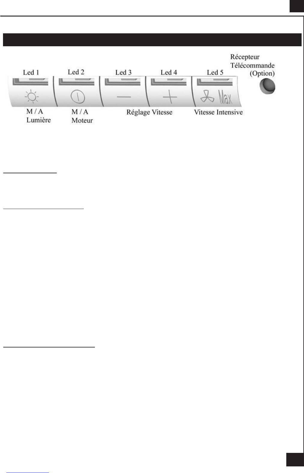
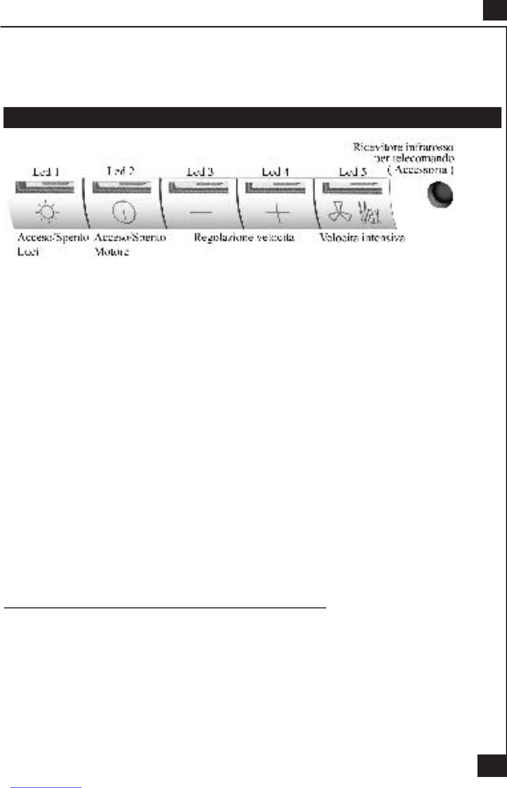
490263
39
Verklein
Vergroot
Pagina terug
1/56
Pagina verder
NOTICE D’INSTALLATION ET D’UTILISATION
INSTRUCTIONS FOR INSTALLATION AND DIRECTIONS FOR USE
MONTAGE- UND GEBRAUCHSANWEISUNG
LIBRETTO DI ISTRUZIONI
INSTRUCCIONES DE INSTALACION E UTILIZACION
MONTAGE- EN GEBRUIKSHANDLEIDING
ESPACE Murale
Downloaded from www.Manualslib.com manuals search engine
F SOMMAIRE
RACCORDEMENT ÉLECTRIQUE
CONSEILS D’INSTALLATIONS
POSE DE L’APPAREIL
FONCTIONNEMENT
CONSEILS D’UTILISATIONS
ENTRETIEN
GARANTIE ET SERVICE APRÈS-VENTE
REMARQUES
D INHALT
NETZANSCHLUSS
MONTAGEHILFEN
MONTAGE DES GERÄTES
BETRIEB DES GERÄTES
NUTZUNG
WARTUNG UND REINIGUNG
GARANTIE UND KUNDENDIENST
WICHTIGE HINVEISE
E SUMARIO
CONEXION ELECTRICA
CONSEJOS DE INSTALACION
INSTALACION DEL APARATO
FUNCIONAMIENTO
CONSEJOS DE UTILIZACION
MANTENIMIENTO
GARANTIA Y ASSISTENCIA TECNICA
NOTA
GB CONTENTS
ELECTRICAL WIRING
INSTALLATION ADVICE
FITTING THE APPLIANCE
OPERATION
USEFUL HINTS
MAINTENANCE
GUARANTEE AND AFTER-SALES-SERVICES
REMARKS
I CONTENUTI
COLLEGAMENTO ELETTRICO
CONSIGLI DI INSTALLAZIONE
POSA DELL’ APPARECCHIO
FUNZIONAMENTO
CONSIGLI DI UTILIZZO
MANUTENZIONE
GARANZIA ED ASSISTENZA TECNICA
NOTE
NL INHOUD
ELECTRISCHE BEDRADING
MONTAGE AANWIJZING
AANSLUITEN VAN HET APPARAAT
FUNKTIONEREN
GEBRUIKSADVIES
ONDERHOUD
AFTER SALES SERVICE
OPMERKINGEN
Downloaded from www.Manualslib.com manuals search engine
1
F
Nous vous remercions de la conance que vous nous avez accordée en choisissant un appareil de la
gamme ROBLIN.
Celui-ci a fait l’objet de toute notre attention dans sa conception et sa réalisation.
An qu’il vous donne entière satisfaction, nous vous recommandons de lire avec attention cette notice
qui vous expliquera comment l’installer, l’utiliser et l’entretenir dans les meilleures conditions.
La présente notice d’emploi vaut pour plusieurs versions de l’appareil. Elle peut contenir des descriptions
d’accessores ne gurant pas dans votre appareil.
1 RACCORDEMENT ÉLECTRIQUE.
• La hotte est équipée d’un cordon d’alimentation de type HO5VVF 3 x 0,75 mm² comportant une
che normalisée 10/16 A avec système de mise à la terre.
Mode de protection : classe 1. Tension d’alimentation : 220-240 V mono - 50/60Hz.
Vérier que la tension du secteur est identique aux valeurs indiquées sur la plaque signalétique à l’inté-
rieur de la hotte
• Si la hotte est raccordée directement sur le réseau sans sa che, un interrupteur omnipolaire avec
une ouverture de contact de 3 mm doit être installé avant la hotte. Le l de terre (Jaune / vert) ne doit pas
être interrompu par cet interrupteur.
2 CONSEILS D’INSTALLATION.
• Pour un fonctionnement idéal, nous vous conseillons une plage de hauteur de pose qui se situe de
0,65 m à 0,70 m au-dessus du plan de cuisson. Toutefois, il est formellement interdit d’installer toute
hotte ou groupe d’aspiration à une distance inférieure à 0,65 m du plan de travail (risque d’inammation
des ltres). La fumée doit monter naturellement vers la zone de captation.
• Respecter le diamètre de sortie de l’appareil : la hotte ne doit en aucun cas être raccordée à un
conduit de ventilation mécanique contrôlée (V.M.C.).
• Lorsqu’on évacue l’air vicié dans un conduit d’évacuation, veiller à ce que celui-ci ne soit pas déjà
exploité à véhiculer des gaz ou fumées provenant d’appareils alimentés par une énergie autre qu’électri-
que.
• Positionner le plan de cuisson au plus près de l’évacuation et éviter la formation de coudes sur la
gaine, an de réduire au maximum les pertes de charges.
• Dans tous les cas d’installation, veiller au bon renouvellement d’air de la cuisine. Penser à effectuer
une ou des entrées d’air par une grille de section égale ou supérieure au diamètre du tuyau
d’évacuation, an de ne pas mettre la cuisine en dépression.
• Prévoir une aération sufsante lorsqu’un appareil de cuisson ou autre utilise simultanément l’air
ambiant de la pièce où est installée la hotte.
• La dépression maximum crée dans la pièce doit être inférieure à 0.04 mbar, ce qui évite un retour de
gaz de combustion.
• L’appareil doit être positionné de telle façon que la che d’alimentation soit accessible.
• Cet appareil ne doit pas être utilisé par des personnes (y compris les enfants) ayant des capacités psy-
chiques, sensorielles ou mentales réduites, ni par des personnes n’ayant pas l’expérience et la connais-
sance de ce type d’appareils, à moins d’être sous le contrôle et la formation de personnes responsables
de leur sécurité.
Les enfants doivent être surveillés pour s’assurer qu’ils ne jouent pas avec l’appareil.
3 POSE DE L’APPAREIL.
Montage et raccordement doivent être réalisés par un installateur* qualié.
(*) Le non-respect de cette condition entraîne la suppression de la garantie du constructeur et
tout recours en cas d’accident.
Attention: prendre bien soin d’employer les chevilles adaptées au support, se renseigner au près
des fabricants, effectuer un scellement si nécessaire. La société décline toute responsabilité en
Downloaded from www.Manualslib.com manuals search engine
2
F
cas d’accrochage défectueux dû au perçage et chevillage.
1) Tracer sur la paroi une verticale jusqu’au plafond à l’emplacement de la hotte au centre de la zone
prévue pour le montage de la hotte (Fig.1, rep. 1). Cette ligne sert pour aligner verticalement les diffé-
rentes parties.
2) Positionner le support de conduit ( Rep. 2), centré sur la verticale à 1 à 2 mm du plafond ou de la
limite supérieure et marquer sur la paroi les deux alésages du support. Effectuer sur la paroi deux trous
avec un foret Ø 8 mm. Fixer le support de conduit (Rep. 2) à l’aide des vis 4.5 x 50 et des chevilles
fournies.
3) Dénir le bas de la hotte (Rep 3) an de xer les supports au mur (Fig 3, Rep 4).
Marquer un point sur la ligne verticale à une distance du plan de cuisson de :
d = 1102 min (mesure sans crédence).
d = hauteur crédence (719 mm) + 402 mm (mesure avec crédence).
La hauteur H est la hauteur minimum en mm du plan de cuisson au bas de la hotte (Rep. 3).
Crédence (Option) : La hauteur de la hotte par rapport au plan de cuisson est déterminée, dans ce
cas par la hauteur de la crédence Rep B et par l’éventuel dosseret du plan de travail. La crédence doit
être montée avant le corps de la hotte et si l’on désire la xer contre le mur tant en haut qu’en bas, il est
nécessaire de la positionner à la juste hauteur. Etant donné qu’il s’agit d’une opération compliquée, elle
doit être effectuée exclusivement par l’installateur de la cuisine ou par du personnel compétent connais-
sant toutes les dimensions nales des meubles.
Effectuer sur la paroi 4 trous avec un foret Ø 8 mm. Fixer les support (Rep. 4) à l’aide des vis 4.5 x 45
et des chevilles fournies.
4) Montage du corps de la hotte :
Accrocher le corps (Rep 5) sur les supports muraux.
Parfaire le réglage d’alignement de l’ensemble, à l’aide des vis TH 5 x 25 des supports, ainsi que l’incli-
naison à l’aide des 2 vis 5 x 25 mm TC.
Après avoir effectué tous les réglages d’alignement de l’ensemble de la hotte, verrouiller celle-ci par une
vis de xation positive (Rep 8), an de garantir la sécurité d’accrochage.
5) Raccordement:
Pour la version Evacuation Extérieure :
a- Mettre en place le clapet anti-retour (Rep. 8) sur la sortie de l'appareil (Rep. 6), puis le telescopique
et raccorder le tuyau exible (Fig. 6) à l’évacuation extérieure et la sortie de l’appareil . Fixer l’ensemble
à l’aide de colliers ou de ruban adhésif appropriés.
b- Enlever le ltre à graisse , puis s'assurer que le connecteur du cable d'alimentation soit bien branché
dans la prise du moteur (Fig. 5).Raccorder électriquement la hotte (Voir paragraphe Raccordement
Electrique) et vérier le bon fonctionnement de l’éclairage, du moteur et du changement des vitesses
d’aspiration.
c- Emboîter le haut de conduit dans le bas de conduit télescopique (Fig. 1 - Rep. 7a & b) et xer le haut
de conduit au support Rep. 2 par 2 vis M4 Rep. 12c fournies. Puis coulisser le bas de conduit jusqu’au
bloc moteur.
Pour la version Recyclage:
a- Fixer le déecteur Rep. R sur la xation du haut de conduit, le déecteur est xé avec les mêmes vis
que le support de haut de conduit (Fig. 2 - Rep. 2).
b- Installer un tuyau de diamètre approprié (Non fourni) entre la sortie de l’appareil et à l’entrée du
déecteur. Fixer l’ensemble à l’aide de colliers ou de ruban adhésif appropriés.
c- Enlever le ltre à graisse, puis s'assurer que le connecteur du cable d'alimentation soit bien branché
dans la prise du moteur (Fig. 5). Raccorder électriquement la hotte (Voir paragraphe Raccordement
Electrique) et vérier le bon fonctionnement de l’éclairage, du moteur et du changement des vitesses
d’aspiration.
d- Placer la cartouches à charbon actif dans son logement en exerçant une pression sur les languettes
A (Fig. 4).
e- Emboîter le haut de conduit dans le bas de conduit télescopique (Fig. 1 - Rep. 7a & b) et xer le haut
de conduit au support Rep. 2 par 2 vis M4 Rep. 12c fournies. Puis coulisser le bas de conduit jusqu’au
bloc moteur.
Downloaded from www.Manualslib.com manuals search engine
3
F
4 FONCTIONNEMENT
a) Conguration
Evacuation extérieure ou recyclage :
Votre hotte est programmée pour fonctionner en mode évacuation extérieure. Si vous souhaitez l’utiliser en
mode recyclage, vous devez impérativement la congurer suivant la procédure suivante :
Mise en recyclage ( l’air est ltré puis renvoyé dans la cuisine) :
Moteur et éclairage éteints, appuyer sur la touche (+) jusqu’aux clignotements des 5 leds :
Deux clignotements des 5 leds indiquent l’enregistrement de la mise en recyclage.
Retour en mode évacuation ( L’air est ltré puis évacué à l’extérieur de l’habitation):
Moteur et éclairage éteints, appuyer sur la touche (+) jusqu’aux clignotements des 5 leds :
Un clignotement des 5 leds indiquera l’enregistrement de la mise en évacuation extérieure.
b) Fonctions de base :
Eclairage :
Mise en marche en appuyant sur la touche 1 (lumière). La led 1 visualise l’état de l’éclairage
Moteur :
Mise en marche en appuyant sur la touche 2 (moteur). Il est possible de modier le débit d’aspiration de
la hotte à l’aide des touches vitesse + et vitesse – , en gardant la touche enfoncée jusqu’à l’obtention de
la vitesse désirée. Le niveau de vitesse est visualisé par les leds 2, 3, 4 qui s’allument au fur et à mesure
de l’accroissement de la vitesse :
Led 2 = niveau minimum
Led 2 et 3 = niveau intermédiaire
Led 2, 3 et 4 = niveau élevé
Un débit d’aspiration maximal peut être obtenu directement en appuyant sur la touche vitesse intensive
(5 ).F
c) Fonctions complémentaires :
• Vitesse intensive temporisée
Pour obtenir une bonne efcacité d’évacuation, nous vous conseillons en début de cuisson une période de
fonctionnement en position intensive. Elle créera un ux d’air permettant de capter les premières fumées
ou vapeurs dès leur apparition. Pour cette fonction il convient de suivre la procédure suivante :
- Mettre le moteur en marche (touche 2), puis sélectionner à l’aide des touches (+) et (-) la vitesse souhaitée
pendant la cuisson.
- Appuyer sur la touche 5 (vitesse intensive). Cette fonction peut être arrêtée en appuyant à nouveau sur
la touche 5.
Temporisation de 5 minutes de l’arrêt de la vitesse intensive:
Par défaut cette fonction n’est pas activée.
Pour accéder à la programmation de cette fonction, la lumière doit être éteinte et le moteur arrêté.
Appuyer sur la touche réglage vitesse (-) :
Downloaded from www.Manualslib.com manuals search engine
4
F
Un clignotement des Leds 2, 3, et 4 = fonction désactivée.
Deux clignotements des Leds 2, 3, et 4 = fonction activée.
Il est possible d’arrêter manuellement la vitesse intensive avant le délai de 5 minutes en appuyant à nouveau
sur la touche 5 (Vitesse intensive).
Pendant cette temporisation de 5 minutes, l’indication de saturation ltres est désactivée.
Si un arrêt différé de la hotte est programmé, la vitesse intensive commandée manuellement ou temporisée
sera désactivée par cet arrêt différé après 5, 10 ou 15 minutes. Il est possible d’arrêter manuellement la vi-
tesse intensive avant l’arrêt différé de la hotte en appuyant à nouveau sur la touche 5 (Vitesse intensive).
Arrêt différé :
Cette fonction permet, après l’arrêt de la cuisson, d’évacuer les dernières fumées et odeurs résiduelles
et en n de cuisson, d'arrêter totalement la hotte (moteur + éclairage).
Pour accéder à la programmation de ce réglage la lumière doit être éteinte et le moteur arrêté.
Appuyer sur la touche vitesse intensive 5 :
- 2 clignotements des leds 1 & 5 conrmeront l’enregistrement de l’arrêt après 5 minutes.
- 3 clignotements des leds 1 & 5 conrmeront l’enregistrement de l’arrêt après 10 minutes.
- 4 clignotements des leds 1 & 5 conrmeront l’enregistrement de l’arrêt après 15 minutes.
- 1 seul clignotement des leds 1 & 5 conrmera la suppression de la fonction arrêt différé.
La hotte peut ensuite être mise en marche sur la vitesse choisie. Le clignotement des leds 2, 3, 4 (sui-
vant la vitesse initialement prévue) indiquera que la fonction arrêt différé est bien programmée :
- 1 clignotement = arrêt après 5 minutes
- 2 clignotements = arrêt après 10 minutes
- 3 clignotements = arrêt après 15 minutes
• Indication de saturation des ltres métalliques :
Après 200 heures de fonctionnement 1 bref clignotement de la Led 1 indique qu’il faut nettoyer les
ltres métalliques (voir paragraphe entretien)
Pour accéder à la remise à zéro de la fonction indiquant la saturation des ltres, la lumière doit être
éteinte et le moteur arrêté.
Appuyer sur la touche (+) pendant 3 à 4 secondes. Le clignotement des Leds 1, 2, 3, 4, et 5 conrme la
remise à zéro.
• Indication de saturation des ltres charbon :
Après 400 heures de fonctionnement 2 brefs clignotements de la Led 1 indique qu’il faut remplacer
les ltres charbon et nettoyer à nouveau les ltres métalliques.
Pour activer la fonction Indication de saturation ltre charbon, la lumière doit être éteinte et le moteur
arrêté. Appuyer sur la touche (+) pendant 10 secondes.
1 clignotement des Leds 1, 2, 3, 4, et 5 = fonction désactivée.
2 clignotements des Leds 1, 2, 3, 4, et 5 = fonction activée.
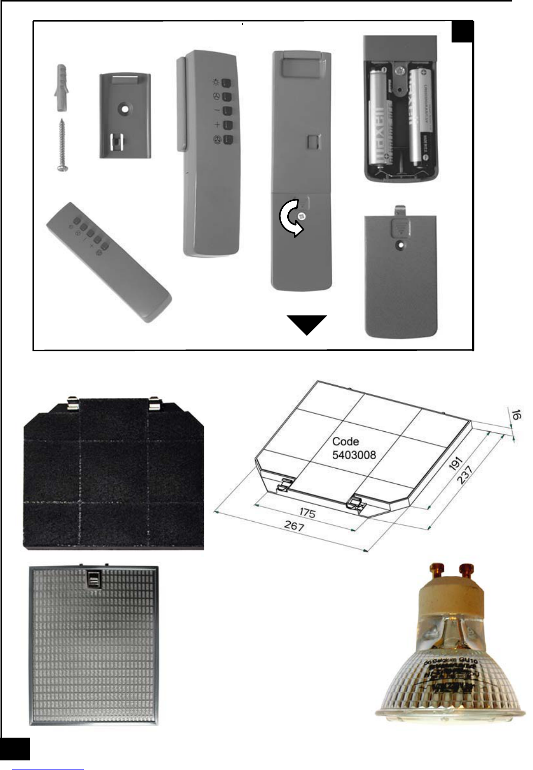
La méthode de remplacement de la cartouche est indiquée au paragraphe 3 (Recyclage)
• Conguration réception télécommande :
Votre hotte est programmée pour fonctionner sans réception télécommande. Si vous souhaitez l’utiliser
avec la télécommande, vous devez impérativement la congurer suivant la procédure suivante :
Moteur et éclairage éteints, appuyer sur la touche 1 (éclairage) jusqu’au clignotement de la led 1 :
Deux clignotements de la led 1 indiquent que la télécommande est activée.
Un clignotement de la led 1 indique que la télécommande est désactivée.
Attention, la télécommande doit être équipée de piles alcalines standards : LR003-AAA, 1.5V comme décrit
Fig. 5. Ces piles devraient assurer un usage optimum de longue durée et doivent être positionnées correc-
tement, elles peuvent exploser si elles sont endommagées ou exposées à la chaleur. Ne pas les jeter dans
le feu. An de préserver l’environnement, merci de déposer ces piles dans un conteneur approprié.
5 CONSEILS D’UTILISATION
• Pour obtenir une efcacité maximum d’absorption des fumées ou des vapeurs, faire fonctionner
l’appareil 5 minutes environ avant et après la cuisson des aliments; La première vitesse est conseillée
Downloaded from www.Manualslib.com manuals search engine
5
pour les cuissons à feu doux et pour les sauces. La deuxième pour les cuissons soutenues, grillades et
friteuses. La troisième est indiquée pour les cuissons à forte émanation de graisses et vapeur.
• IMPORTANT . NE JAMAIS FLAMBER DE METS AU DESSOUS DE L’APPAREIL
Ne laissez jamais de ammes libres sous la hotte en fonctionnement.
• Les fritures nécessitent une surveillance permanente, l’huile surchauffée pouvant s’enammer.
6 ENTRETIEN
Déconnecter le câble d’alimentation pour toute intervention électrique.
L’appareil a été conçu pour faciliter au maximum les opérations d’entretien, synonyme de bon fonctionne-
ment et rendement de l’appareil dans le temps.
• Nettoyage des ltres métalliques.
Il est indispensable de procéder à un NETTOYAGE PÉRIODIQUE de ces ltres à la main (avec un
détergent liquide à l’eau tiède et rinçage) ou au lave- vaisselle (tous les deux mois environ pour une
utilisation normale).
• Carrosserie.
Nettoyer régulièrement celle-ci en utilisant des produits détergents, non abrasifs et une éponge légère-
ment humide. N’utilisez jamais d’éponges ou de chiffons trempés.
N’introduisez aucun objet, ni les mains dans l’ouverture servant à l’évacuation de l’air.
• Conduit d’évacuation.
Vérier tous les 6 mois le bon écoulement de l’air vicié.
Observer les prescriptions réglementaires locales concernant l’évacuation de l’air vicié.
• Éclairage.
Avant toute intervention sur l’appareil, mettre l’interrupteur d’allumage des lampes en position éteinte.
Ne pas dépasser la puissance prescrite et ne pas changer de type de lampe.
7 GARANTIE ET SERVICE APRÈS-VENTE
• En cas d’anomalie de fonctionnement, prévenez votre installateur qui devra vérier l’appareil et son
raccordement.
• Dans le cas où un composant électrique viendrait à être endommagé, celui-ci ne peut être remplacé
que par un atelier de réparation reconnu par le fabricant, car des outils spéciaux sont nécessaires.
• Débrancher complètement l’appareil.
• Exigez toujours l’utilisation de pièces de rechange d’origine. La non observation de cette prescription
peut compromettre la sécurité de l’appareil.
• Lors de la commande de pièces détachées, rappeler le numéro de l’appareil inscrit sur la plaque
signalétique située à l’intérieur de la hotte.
• Seule la facture d’achat de l’appareil fera foi pour l’application de la garantie contractuelle.
Cette garantie ne couvre pas les consommables comme :
- L’éclairage : lampes incandescentes, halogènes ...
- Les ltres.
8 REMARQUES
Cet équipement est conforme à la norme européenne sur la basse tension 2006/95/CE relative à la
sécurité électrique et aux normes européennes: 2004/108/CE relative à la compatibilité électromagnéti-
que et 93/68 relative au marquage CE.
Lorsque ce symbole
d’une poubelle à roue barrée est attaché à un produit, cela signie que le
produit est couvert par la Directive Européenne 2002/96/EC. Votre produit est conçu et fabriqué avec
des matériaux et des composants de haute qualité, qui peuvent être recyclés et utilisés de nouveau.
Veuillez vous informer du système local de séparation des déchets électriques et électroniques. Veuillez
agir selon les règles locales et ne pas jeter vos produits usagés avec les déchets domestiques usuels.
Jeter correctement votre produit usagé aidera à prévenir les conséquences négatives potentielles
contre l’environnement et la santé humaine.
F
Downloaded from www.Manualslib.com manuals search engine
6
GB
Thank you for buying a Roblin product which has been manufactured to the highest quality standards to
meet your requirements.
We recommend you carefully read this booklet in which you will nd instructions for installation, hints for
use and maintenance.
The Instructions for Use apply to several versions of this appliance. Accordingly, you may nd descrip-
tions of individual features that do not apply to your specic appliance.
1 ELECTRICAL
• This cooker hood is tted with a 3-core mains cable with a standard 10/16A earthed plug.
Alternatively the hood can be connected to the mains supply via a double-pole switch having 3mm
minimum contact gap on each pole.
• Before connecting to the mains supply ensure that the mains voltage corresponds to the voltage on
the rating plate inside the cooker hood.
• Technical Specication: Voltage 220-240, single phase ~50/60Hz.
2 INSTALLATION ADVICE
• Ensure the cooker hood is tted in compliance with the recommended xing heights.
• To ensure the safe operation of this cooker hood, we recommend that the hood should not be tted
below 65cm (for electric) or (70cm for gas) the measurements taken from the surface of the cooking
appliance to the underside of the cooker hood.
• It is a possible re risk if the hood is not sited as recommended.
• T
o ensure the best results, the cooking fumes should be able to rise naturally towards the inlet grilles
on the underside of the cooker hood and the cooker hood should be positioned away from doors and
windows, which will create turbulence.
• Ducting
• If the room where the hood is to be used contains a fuel-burning appliance such as a central heating
boiler then its ue must be of the room sealed or balanced ue type.
• If other types of ue or appliances are tted ensure that there is an adequate supply of fresh air to the
room. Ensure the kitchen is tted with an airbrick, which should have a cross-sectional measurement
equivalent to the diameter of the ducting being tted, if not larger.
• The ducting system for this cooker hood must not be connected to any existing ventilation system,
which is being used for any other purposes or to a mechanically controlled ventilation ducting.
• The ducting used must be made from re retardant materials and the correct diameter must be used,
as incorrect sized ducting will affect the performance of this cooker hood.
• When the cooker hood is used in conjunction with other appliances supplied with energy other than
electricity, the negative pressure in the room must not exceed 0.04 mbar to prevent the fumes from
combustion being drawn back into the room.
• The appliance is for domestic use only and should not be operated by children or people who are
inrm without supervision.
• This appliance must be positioned so that the wall socket is accessible.
• This appliance is not intended for use by persons (including children) with reduced physical, sensory
or mental capabilities, or lack of experience and knowledge, unless they have been given supervision or
instruction concerning use of the appliance by a person responsible for their safety.
Children should be supervised to ensure that they do not play with the appliance.
3 FITTING
Any permanent electrical installation must comply with the latest regulations concerning this type of
installation and a qualied electrician must carry out the work. Non-compliance could cause serious
accidents or injury and would deem the manufacturers guarantee null and void.
IMPORTANT - The wires in this mains lead are coloured in accordance with the following code :
- green / yellow : earth - blue : neutral - brown : live
As the colours of the wires in the mains lead of this appliance may not correspond with the coloured
Downloaded from www.Manualslib.com manuals search engine
7
GB
markings identifying the terminals in your plug, proceed as follows.
- The wire which is coloured green and yellow must be connected to the terminal in the plug which is
marked with the letter E or by the earth symbol or coloured green or green and yellow.
- The wire which is coloured blue must be connected to the terminal which is marked with the letter N or
coloured black.
- The wire which is coloured brown must be connected to the terminal which is marked with the letter L or
coloured red.
ATTENTION: Do not forget to use adequate plugs to the support brackets. Enquire after the manu-
facturers. Do an embedding if necessary. The manufacturer accepts no responsibility in case of a
faulty hanging due to the drilling and the setting up of plugs.
GB
1) Draw a vertical line onto the wall from the centre of the cooking appliance up to the ceilling, using a
spirit level and a marker pen as illustrated in Fig. 1 - item 1. This is to ensure the correct alignment
of the chimney hood.
2) Place the brackets item 2 on the wall about 1 or 2 mm from the ceiling or from the upper limit, aligning
its centre on the vertical line. Mark the two eyelet holes of the bracket onto the wall. Drill the holes
for the xing bracket using an 8 mm masonry bit. Fix the chimney bracket item 2 using the 4.5 x 50
mm screws and rawl plugs supplied.
3) Mark a point on the vertical line at a distance from the cooking appliances of:
d = 1102 mm (Measurement without splashback).
d = height of the splashback (719 mm) + 402 mm (Measurement with splashback).
The distance H is the minimum height in mm from the cooking appliances to the bottom edge item 3 of
the front panel of the hood. Draw a horizontal line through the vertical as illustrated in Fig. 1.
Splashback (optional): When a splashback is to be tted, the distance between the hood and the cook-
ing appliances will be determined by the height of the splashback item B and whether or not there
is a raised back on the worktop. The splashback is to be installed before installing the canopy. If
the splashback is to be xed to the wall using both the top and bottom xing holes, Care must be
taken to ensure that the splashback is tted at the correct height before xing the base units or at
least the worktop covering them. As this is a complex operation, it should only be undertaken by
the technician installing the kitchen units or by a competent person who knows the nal dimensions
of the units.
Mark the hole centres for the canopy xing brackets item 4 at item B mm as illustrated in Fig. 3.
Drill the 4 holes for the xing brackets using an 8 mm masonry bit. Fix the wall brackets item 4 using
the 4.5 x 45 mm screws and rawl plugs supplied.
4) Hook the canopy item 5 onto the wall brackets item 4 as illustrated in Fig. 3. To ensure the cooker
hood is aligned correctly adjust the screws on the top of the canopy as illustrated in Fig. 3. When the
hood is aligned correctly mark the hole centre on the wall for the security xing screw item8, which
is located in the right hand bracket on the top of the canopy. Unhook the canopy from the wall and
drill the hole for the security xing screw. Hook the canopy onto the wall and x the No 4,5 x 50mm
headed screw and rawl plug to secure the canopy to the wall.
5) Ducting:
The hood is more effective when used in the extraction mode (ducted to the outside). When the cooker
hood is ducted to the outside, charcoal lters are not required.The ducting used must be 150 mm (6
INS), rigid circular pipe and must be manufactured from re retardant material, produced to BS.476
or DIN 4102-B1. Wherever possible use rigid circular pipe which has a smooth interior, rather than
the expanding concertina type ducting.
Maximum length of ducting run:
- 4 metres with 1 x 90° bend.
- 3 metres with 2 x 90° bends.
- 2 metres with 3 x 90° bends.
The above assumes our 150 mm (6 INS) ducting is being installed. Please note ducting components
Downloaded from www.Manualslib.com manuals search engine
8
and ducting kits are optional accessories and have to be ordered, they are not automatically supplied
with the chimney hood.
IN THE EXTRACTION MODE:
a. Place the anti-backow ats item 8 over the round outlet item 6, the telescopic duct and connect the
ducting 150mm (6 INS) over the round outlet on top of the canopy and secure the connections with
appropriate clamping rings or adhesive tape (Fig. 6).
b. Remove the grease lters (see paragraph Maintenance) Fig. 5 being sure that the connector of the
mains cable is correctly inserted in the socket placed on the sides of the fan. Before tting the chimney
to the canopy make the electrical connection as described in the section titled ELECTRICAL. When
the electrical connection has been made, test the lights and the fan motor.
c. Each chimney stack consists of two sections. Fit the upper sections (Fig. 1 - item 7a & b) rst by
expanding the chimneys slightly to allow them to clamp around the bracket item 2 and secure the
chimney stacks to the brackets using the two M4 screws item 12c provided. Fit the lower chimney
sections by expanding the chimneys slightly to allow them from the top of the canopy to clamp around
the upper chimney sections.
IN THE RECIRCULATION MODE:
a. Fit the recirculation spigot R onto the upper chimney wall bracket using the same xing screws (Fig.
2 item 2).
b. Connect the ducting 150mm (6 INS) not provided between motors item 6 and the recirculation spigot
and secure the connections with appropriate clamping rings or adhesive tape.
c. Remove the grease lters (see paragraph Maintenance) Fig. 5 being sure that the connector of the
feeding cable is correctly inserted in the socket placed on the side of the fan. Before tting the chimney
to the canopy make the electrical connection as described in the section titled ELECTRICAL. When
the electrical connection has been made, test the lights and the fan motor.
d. Insert the charcoal lter into the base of the motor housing and secure the lter with two metal secur-
ing straps item A as illustrated in Fig. 4.
e. Each chimney stack consists of two sections. Fit the upper sections (Fig. 1 - item 7a & b) rst by
expand-ing the chimneys slightly to allow them to clamp around the bracket item 2 and secure the
chimney stacks to the brackets using the two M4 screws item 12c provided. Fit the lower chimney
sections by expanding the chimneys slightly to allow them from the top of the canopy to clamp around
the upper chimney sections.
4 OPERATION
A - EXTRACTION OR RECYCLING :Your cooker hood is supplied in the extraction mode. To use the cooker
hood in the recycling mode re-programme the hood as follows:
Starting in the recycling mode (the contaminated air passes into the hood through the grease lters and
the purifying activated charcoal lter and back out into the kitchen through grilles).
Press the ‘+’ button (while the motor and lights are switched ‘OFF’) until the ve LED lights will ash twice
to indicate conrmation that the cooker hood is in the recycling mode.
GB
Downloaded from www.Manualslib.com manuals search engine
9
Reverting to the extraction mode (The cooker hood is ducted to the outside).
Press the ‘+’ button (while the motor and lights are switched ‘OFF’) until the ve LED lights will ash once
to indicate conrmation that the cooker hood is in the extraction mode.
GB
B - BASIC INSTRUCTIONS
Lighting
Press LED button 1 to switch ‘ON’ the lights and the LED will illuminate to conrm the lights are switched
‘ON’.
Motor
Press LED button 2 to switch ‘ON’ the fan motor (and adjust the speed of the fan motor by pressing the
LED button ‘+’ and ‘-‘) and the LED lights 2, 3 and 4 will illuminate. The fan speed will be increased if
constant pressure is kept on the (+) button.
LED 2 : Minimum speed - cooking with one pan or simmering
LED 2 & 3 : Medium speed - normal cooking with up to 4 pans
LED 2, 3 & 4 : Maximum speed - frying and cooking foods with strong odours
Press LED button 5 to obtain the boost position for maximum effect and the LED will illuminate to conrm
fan is switched ‘ON’.
C - COMPLEMENTARY INSTRUCTIONS
Boost speed :
To obtain the best performance it is advisable to switch ‘ON’ the cooker hood a few minutes (in the boost
setting) before you start cooking. To program the complementary function, proceed as follows:
- Press LED button 2 to switch ‘ON’ the fan motor and adjust the speed of the fan by pressing the LED
button ‘+’ and ‘-‘. You should keep applying pressure to the ‘+’ and ‘-‘ button until the required speed is
selected.
- Press LED button 5 (boost speed) to switch ‘ON’ the fan motor in the boost setting. Press LED button 5
to switch ‘OFF’ the boost setting immediately.
It is advisable too that you should leave it running in the boost setting for approximately 5 minutes after
nishing.
Pre-set stop of the boost speed :
A pre-set stop after 5 minutes of the boost speed is available.
Your cooker hood is supplied with a deactivated pre-set stop of the boost speed. To use the cooker hood
with a pre-set stop of the boost speed re-programme the hood as follows:
The lights and the fan motor should be switched ‘OFF’ to set the timer.
Push the LED button ‘-’ until the LED lights will ash :
One ash of the LED lights 2,3, and 4 = function is switched ‘OFF’.
Two ashes of the LED lights 2,3, and 4 = function is switched ‘ON’.
While the 5 minutes timer is running, It is available to stop immediately the boost speed by pressing the
led button 5.
While the 5 minutes timer is running, the indication of saturation of the lters is switched ‘OFF’.
If a pre-set stop for the hood is switched ‘ON’ and the 5 minutes timer is still running, the boost speed will
be switched ‘OFF’ together with the pre-set stop for the hood after the count down of 5, 10 or 15 minutes.
It is available to stop the boost speed before the count down of the preset stop of the hood by pressing
the led button 5.
Pre-set stop for the hood :
This function allows you to program the cooker hood to automatically stop cooking after a pre-set period.
The lights and the fan motor should be switched ‘OFF’ to set the timer.
Proceed by repeatedly pressing the LED button 5 (Boost speed):
Two ashes of the LED button 1 & 5 = 5 minutes delay.
Three ashes of the LED button 1 & 5 = 10 minutes delay.
Four ashes of the LED button 1 & 5 = 15 minutes delay.
GB
Downloaded from www.Manualslib.com manuals search engine
10
One ash of the LED button indicates the function is switched ‘OFF’.
You can switch the cooker hood ‘ON’ and adjust the speed. The LED buttons 2, 3 and 4 will ash to
indicate the fan motor is switched ‘ON’ and which speed has been selected.
One ash = stop after 15 minutes.
Two ashes = stop after 10 minutes.
Three ashes = stop after 15 minutes.
• Indication of saturation of the metal grease lters :
After 200 hours use, one quick ash of the LED 1 will indicate that you must clean the metal grease
lters. (See chapter on ‘Maintenance’).
To reset the 200 hours timer back to zero requires the motor and lights must be switched ‘OFF’; then and
proceed as follows:
Press the LED button ‘+’ for 3 to 4 seconds and the LED lights 1,2,3, 4 and 5 will ash to conrm the
programme has been reset to zero.
8GB
• Indication of saturation of the active charcoal lter :
After 400 hours use, two quick ash of the LED 1 will indicate that you must replace the active charcoal
lter and clean the metal grease lters. (See chapter on ‘Maintenance’).
To reset the 400-hour timer the motor and lights must be switched ‘OFF’.
Push the LED button ‘+’ for 10 seconds.
One ash of the LED lights 1,2,3,4 and 5 = function is switched ‘OFF’.
Two ashes of the LED lights 1,2,3,4 and 5 = function is switched ‘ON’.
Instructions for replacing the active charcoal lter are given in the chapter on ‘Recycling’.
Pre-set remote control handset
Your cooker hood is supplied with a deactivated remote control receiver. To use the cooker hood with a
remote control re-programme the hood as follows:
Press the LED button (Lighting) ‘1’ while the motor and lights are switched ‘OFF’, until the LED lights 1 will
ash to conrm the programme has been activated :
One ash of the LED lights 1 = function is switched ‘OFF’.
Two ashes of the LED lights 1 = function is switched ‘ON’.
Caution, the remote control handset must be tted with standard LR03-AAA size 1.5V zinc-carbon alkaline
batteries as illustrated Fig. 5. These batteries should give a long life and constant discharge throughout their
life. These batteries must be disposed of properly and could explode if damaged or exposed to heat.
Do not dispose of on re. Dispose of batteries in the appropriate sort container to protect the environ-
ment.
• Setup Process
Modication: How to adjust the internal microprocessor data to suit the type of motor tted to this
appliance and the supply frequency of 50 or 60 Hz..
1 - Disconnect the cooker hood from the mains supply.
2 - Push the button 0/1 MOTOR.
3 - Reconnect the mains supply while pushing the button 0/1 MOTOR for at least 2 seconds.
4 - Release the button 0/1 MOTOR (the Leds ash for about 3 seconds : capacity’s conrmation SETUP
PROCESS).
5 - While the LED is ashing select the motor type used while pushing one of the 5 buttons in accordance
with the following:
BUTTON 0/1 Light : Motor EBM PRO 220-240 V AC 50 Hz / 220 V AC 60 Hz.
BUTTON 0/1 Motor : Motor FABER 8/28 e 8/50 220-240 V AC 50 Hz / 220 V AC 60 Hz.
BUTTON Speed ( - ) : Motor EBM MISTRAL 220-240 V AC 50 Hz / 220 V AC 60 Hz.
BUTTON Speed (+ ) : Motor EBM PRO 220-240 V AC 50 Hz / 220 V AC 60 Hz.
GB
Downloaded from www.Manualslib.com manuals search engine
11
BUTTON Intensive speed : Motor FABER K40-K50 220-240 V AC 50 Hz / 220 V AC 60 Hz.
N.B. : If you have not selected a motor type while the LED is ashing the microprocessor will automatically
select the default motor EBM PRO 220 - 240 V AC 50 Hz / 220 V AC 60 Hz.
5 USEFUL HINTS
• To obtain the best performance it is advisable to switch ‘ON’ the cooker hood a few minutes (in the
boost setting) before you start cooking and you should leave it running for approximately 15 minutes after
nishing.
IMPORTANT: NEVER DO FLAMBÉ COOKING UNDER THIS COOKER HOOD
Do not leave frying pans unattended during use as over-heated fat and oil might catch re.
Do not leave naked ames under this cooker hood.
Switch ‘OFF’ the electric and gas before removing pots and pans.
Ensure heating areas on your hotplate are covered with pots and pans when using the hotplate
and cooker hood simultaneously.
6 MAINTENANCE
Before carrying out any maintenance or cleaning isolate the cooker hood from the mains supply.
The cooker hood must be kept clean; a build up of fat or grease can be a re hazard.
Casing
• Wipe the cooker hood frequently with a clean cloth, which has been immersed in warm water containing
a mild detergent and wrung out.
• Never use excessive amounts of water when cleaning particularly around the control panel.
• Never use scouring pads or abrasive cleaners.
Always wear protective gloves when cleaning the cooker hood.
Metal Grease Filters
The metal grease lters absorb grease and dust during cooking to help keep the cooker hood clean
inside. The grease lters should be cleaned once a month or more frequently if the hood is used for more
than 3 hours per day.
To remove and replace the metal grease lters
• Remove the metal grease lters one at a time by releasing the catches on the lters; the lters can
now be removed.
• The metal grease lters should be washed, by hand, in mild soapy water or in a dishwasher.
Allow to dry before replacing.
Active Charcoal Filter
The charcoal lter cannot be cleaned. The lter should be replaced at least every three months or more
frequently if the hood is used for more than three hours per day.
To remove and replace the lter
• Remove the metal grease lters.
• Press against the two retaining clips, which hold the charcoal lter in place and this will allow the lter
to drop down and be removed.
• Clean the surrounding area and metal grease lters as directed above.
• Insert the replacement lter and ensure the two retaining clips are correctly located.
• Replace the metal grease lters.
Extraction tube.
Check every 6 months that the dirty air is being extracted correctly. Comply with local rules and regula-
tions with regard to the extraction of ventilated air.
Lighting.
If the lamp fails to function check to ensure it is tted correctly into the holder. If lamp failure has occurred
then it should be replaced with identical replacement.
Do not replace with any other type of lamp and do not t a lamp with a higher rating.
GB
Downloaded from www.Manualslib.com manuals search engine
12
GB
7 GUARANTEE AND AFTER SALES SERVICE
• In the event of any malfunction or anomaly, notify your tter who will have to check the appli-
ance and its connection.
• In the event of damage to the mains supply cable, this can only be replaced by at approved repair
centre appointed by the manufacturer who have the necessary tools and equipment to carry out any
repairs properly. Repairs carried out by other persons will invalidate the guarantee.
• Use only genuine spare parts. Should these warnings fail to be observed it could affect the safety of
your cooker hood.
• When ordering spare parts quote the model number and serial number written on the rating plate,
which is found on the casing behind the grease lters inside the hood.
• Proof of purchase will be required when requesting service. Therefore, please have your receipt
available when requesting service as this constitutes the date from which your guarantee commenced.
This Guarantee does not cover :
- Damage or calls resulting from transportation, improper use or neglect, the replacement of any light
bulbs or lters or removable parts of glass or plastic.
These items are considered to be consumable under the terms of this guarantee.
8 REMARKS
This appliance complies with European regulations on low voltages Directive 2006/95/CE on electrical
safety, and with the following European regulations: Directive 2004/108/CE on electromagnetic compat-
ibility and Directive 93/68 on EC marking.
When this crossed-out wheeled bin symbol
is attached to a product it means the product is cov-
ered by the European directive 2002/96/EC.Your product is designed and manufactured with high quality
materials and components, which can be recycled and reused.Please inform yourself about the local
separate collection system for electrical and electronic product. Please act according to your local rules
and do not dispose of your old products with your normal household waste. The correct disposal of your
old product will help prevent potential negative consequences for the environment and human health.
OPERATION
Downloaded from www.Manualslib.com manuals search engine
13
Wir danken Ihnen für Ihre Kaufentscheidung und das Vertrauen, welches Sie mit dem Kauf dieses Roblin-
Produktes bewiesen haben.
Dieses Gerät wurde mit einem hohen Maß an Kreativität entwickelt und mit größter Sorgfalt gefertigt.
Um volle Zufriedenheit mit Leistung und Funktion dieser Dunstesse zu erlangen und zu erhalten, empfeh-
len wir dringend, sowohl die Montageanweisung sorgfältig zu beachten und danach zu arbeiten als
auch die « Gebrauchs- und Wartungshinweise « aufmerksam zu lesen und anzuwenden.
Diese Gebrauchsanleitung gilt für mehrere Geräte-Ausführungen. Es ist möglich, dass einzelne Ausstat-
tungsmerkmale beschrieben sind, die nicht auf Ihr Gerät zutreffen.
1 NETZANSCHLUSS
• Die Dunstabzugshaube ist mit einer Anschlußleitung der Art HO5VVF 3 x 0,75 mm
2, die einen Schutz-
stecker 10 / 16 A enthält, ausgestattet. Das entspricht Schutzklasse 1.
Nennspannung : 220-240 V - Wechselstrom : 50/60 Hz.
• Es ist sicherzustellen, daß die Netzspannung den Anschlußwerten auf dem Typenschild im Inneren
der Dunstesse entspricht.
• Beim Anschluß der Dunstesse an das Wechselstromnetz ist ein zweipoliger Schalter mit einem Öff-
nungsweg von wenigstens 3 mm für jeden Pol zwischenzuschalten.
2 MONTAGEHILFEN
• Die Mindest- und Höchstabstände zwischen der Dunstesse und der Kochäche sind zu berücksichtigen.
Wir empfehlen Ihnen einen Abstand von 0,65 m bis 0,70 m über der Kochäche einzuhalten,
um einen optimalen Betrieb des Gerätes zu gewährleisten. Jedoch ist es streng verboten, Dunstessen
oder Einbaugeräte mit einem Abstand, der niedriger als 0,65 m von der Kochäche ist, einzubauen
(Entzündungsgefahr der Filter). Beachten Sie die richtige Ableitung der Kochschwaden (Luftzug kann
Turbulenzen verursachen).
• Der Außendurchmesser am Gebläseabgang des Gerätes ist für die Wahl des Abluft-Rohrsystems
zu berücksichtigen : Die Dunstesse darf keinesfalls an eine Entlüftungsleitung mit Unterdruck angeschlos-
sen werden. Die Abluft darf nicht in einen Schornstein geleitet werden, der für die Abgase von Koch- oder
Heiz-Geräten, (Kohle-, Öl- oder Gas-Öfen oder -Herde) benutzt wird.
• Die Kochstelle (und damit auch die Dunstesse) so planen und installieren, daß möglichst kurze
Wege für eventuelle Abluft-Rohrleitungen erreicht werden. (so wenige Umlenkungen [90°-Bögen] wie
möglich! Keine Querschnittsverengungen!
• Die gute Erneuerung der Luft in der Küche ist zu beachten. Denken Sie daran, einen oder mehrere
Lufteintritte durch eine Öffnung, die den gleichen Durchmesser hat wie die Abluftleitung, vorzusehen.
• Sorgen Sie für eine ausreichende Zuluft, wenn ein Koch- oder anderes Gerät die Luft des Raumes,
in dem die Dunstesse eingebaut ist, gleichzeitig verwendet. Ein gefahrloser Betrieb ist möglich, wenn bei
gleichzeitigem Betrieb von Dunstesse und Feuerstätte im Raum ein Unterdruck von höchstens 0.04 mbar
erreicht wird und ein Rücksaugen der Feuerstättenabgase vermieden wird.
Das Gerät muß so installiert werden, daß der Geräte-Stecker leicht erreichbar ist.
• Dieses Gerät darf nicht von Personen, auch Kindern, mit verminderten psychischen, sensorischen und
geistigern Fähigkeiten, oder von Personen ohne Erfahrung und Kenntnisse benutzt werden, sofern sie
nicht von für ihre Sicherheit verantwortlichen Personen beaufsichtigt und beim Gebrauch des Geräts
angeleitet werden.
Kinder dürfen sich nicht unbeaufsichtigt in der Nähe des Geräts aufhalten und auf keinen Fall mit dem
Gerät spielen.
3 MONTAGE DES GERÄTES
Montage und Anschluß müssen von einem qualizierten Installateur* durchgeführt werden.
(*) Wenn diese Bedingung nicht eingehalten wird, wird die Garantie des Herstellers, sowie jeder
Anspruch im Falle eines Unfalles aufgehoben.
Achtung ! Bitte beachten Sie bei der Montage das Gewicht der kompletten Dunstesse. Die Tragfä-
higkeit der Decke oder alternativ der Trägerplatte für diese Zugbelastung muss vor der Montage
D
Downloaded from www.Manualslib.com manuals search engine
14
geprüft und gegebenenfalls durch die Anbringung von geeigneten Befestigungs-oder Stabilisie-
rungselementen hergestellt werden. Kann eine hinreichende Tragfähigkeit nicht sichergestellt
werden, ist von einer Montage abzusehen.
1) An der Wand eine vertikale Linie 1 (Abb. 1) bis zur Decke zeichnen (Mittellinie des Bereiches, indem
die Haube montiert werden soll), um die zu montierenden Einzelteile vertikal ausrichten zu können.
2) Einen der beiden Bügel 2 (Abb. 1) ca. 1-2 mm von der Decke oder der oberen Begrenzung an die
Wand legen und den Mittelpunkt auf der vertikalen Linie ausrichten. Die beiden ösenförmigen Bohrlöcher
des Bügels an der Wand markieren.
3) Einen Punkt auf der vertikalen Linie kennzeichnen, der folgenden Abstand zur Kochmulde aufweist:
d = min. 1102 (Maß ohne Rückwand).
d =Rückwandhöhe (719 mm) + 402 mm (Maß mit Rückwand). Das Maß H ist die Mindesthöhe in mm
von der Kochmulde zur unteren Frontkante 3.
Rückwand (Optional): Der Abstand der Haube von der Kochmulde wird in diesem Fall von der Höhe
der Rückwand B und des eventuell anzubringenden Aufsatzes an der Arbeitsplatte bestimmt. Die Rück-
wand wird vor Montage des Haubenkörpers angebracht; will man die Rückwandoben und unten mit der
Wand verschrauben, muss sie auf die gewünschte Höhe ausgerichtet werden, bevor der Unterschrank
oder die Arbeitsplatte montiert wird. Da es sich hierbei um einen relativ komplizierten Vorgang handelt,
sollte er nur vom Küchenmontagepersonal oder von fachlich geschulten Personen, die die Endmasse
der Möbel genau kennen, durchgeführt werden.
Für die Unterkante des Gerätes eine Einbauhöhe (3) bestimmen,um die Stützen zu positionieren. (Figur
3, Pos. 4) (Abb. 1& 2)
4) Montage des Haubenkörpers: Der Haubenkörper (5) wird an den Wandstzen befestigt. Die Regelung
und das Ausrichten der Dunstesse von außen mit den Schrauben 5 x 10 der Stützenund mit den zwei
Schrauben 5 x 25 mm kontrollieren. Nachdem Sie alle Einstellungen durchgeführt haben, verriegeln Sie
die Dunstesse durch dieBefestigungsschraube (8), um das unbeabsichtigte Aushängen zu vermeiden.
Diese positiveBefestigungsschraube ist durch eine farbige Aufschrift gekennzeichnet, die sich im Oberteil
desGeräte-Gehäuses bendet.
5) Anschluss für Abluft- oder Umluftbetrieb:
Abluftbetrieb
a- Die Rückstauklappe (Pos .8) am Gerätsausgang anbringen (Pos. 6), der Teleskopscheide auf den
Flansch des Gerätes einfügen. Schlauch am Gerätsausgang anbringen (Abb. 6) und anschliessen. Beim
Anschluss passende Schlauchschellen oder Klebeband benutzen.
b- Entfernen Sie die Fettlter (s. Abschnitt „Wartung“) und versichern Sie sich, dass die Kabelverbindung
in die Steckdose des Gebläses einwandfrei montiert wird (Abb. 5). Das Gerät ans Wechselstromnetz
anschliessen (siehe Abschnitt Netzanschluss) und Funktion von Beleuchtung, Motor und der elektro-
nischen Steuerung (Gebläseleistung) prüfen.
c- Den Oberkamin in den Teleskop-Unterkamin (Abb.1 Pos.7 a+b) einfügen und mit den beigelegten
Schrauben M 4 (Pos. 12 c) an die Stütze (Pos. 2) hängen. Danach den Oberkamin um den Hauben-
körper falzen.
Umluftbetrieb
a- Den Umluftadapter R an den Oberkamin hängen. Der Umluftadapter wird mit denselben Schrauben
wie für die Oberkaminstütze befestigt (Abb. 2 – Pos. 2).
b- Ein Verbindungsrohr/Schlauch mit passendem Durchmesser (nicht im Lieferumfang) am Lufteintritt
D
Downloaded from www.Manualslib.com manuals search engine
15
des Umluftadapters und am Gebläseausgang (Pos. 6) anschliessen. Beim Anschluss passende
Schlauchschellen oder Klebeband benutzen.
c- Entfernen Sie die Fettlter (s. Abschnitt „Wartung“) und versichern Sie sich, dass die Kabelverbindung
in die Steckdose des Gebläses einwandfrei montiert ist (Abb. 5). Das Gerät ans Wechselstromnetz
anschliessen (siehe Abschnitt Netzanschluss) und Funktion von Beleuchtung, Motor und der elektro-
nischen Steuerung (Gebläseleistung) prüfen.
d- Die Stütze der Aktivkohle-Filters befestigen und mittels Druck auf die Elemente A (Abb. 4) Aktivkohle-
Filterkassette einrasten.
e- Den Oberkamin in den Teleskop-Unterkamin (Abb.1 Pos.7 a+b) einfügen und den Oberkamin mit
den beigelegten Schrauben M 4 ( Pos. 12 c) an die Stütze (Pos. 2) hängen. Danach den Oberkamin
um den Haubenkörper falzen.
4 BETRIEB DES GERATES
A ) Ausführung
Abluft- oder Umluftbetrieb
Die Elektronikschaltung der Dunstesse ist für Abluftbetrieb programmiert. Um die Esse für Umluftbetrieb
einzustellen bitte folgende Schritte ausführen :
Umluftbetrieb: (die verschmutzte Luft wird gereinigt und dann wieder in den Raum zurückgeführt.)
Motor und Beleuchtung müssen abgeschaltet sein. Auf den Bedienknopf (+) bis zum Blinken aller 5
LEDs drücken:
Zwei Blinken aller 5 LEDs zeigen an: Funktion Umluftbetrieb = EIN
Zurück in Abluftbetrieb: (die verschmutzte Luft wird gereinigt und dann aus dem Haus geführt).
Motor und Beleuchtung müssen abgeschaltet sein. Auf den Bedienknopf (+) bis zum Blinken aller 5
LEDs drücken:
Zwei Blinken aller 5 LEDs zeigen an: Funktion Abluftbetrieb = EIN
B ) Grundsätzliche Funktionen :
Beleuchtung : Wird durch Druck auf die Schaltertaste 1 (Licht) eingeschaltet. Die LED 1 zeigt den
Zustand der Beleuchtung an.
Gebläse : Wird durch Druck auf die Schaltertaste 2 (Gebläse) eingeschaltet. Die Gebläse-Leistung
kann mittels der >>Stufe: Schaltertaste + << und der >>Stufe: Schaltertaste - <<, durch kurzzeitigen
oder andauernden Druck auf die entsprechenden Schaltertasten modiziert werden, bis die gewünschte
Stufe erreicht ist. Die sogenannten >>MINIMUM<<, MEDIUM<< und >>MAXIMUM<< Stufen werden
durch die LED’s 2, 3, 4, die im Verhältnis zur Veränderung der Gebläseleistung leuchten, angezeigt :
Led 2 = MINIMUM
Led 2 und 3 = MEDIUM
Led 2, 3 und 4 = MAXIMUM
Die sogenannte >>INTENSIV-Stufe<< kann direkt durch Druck auf die Schaltertaste >>INTENSIV-
MAX<<
(5), erreicht werden. Die Laufdauer der Intensivstufe kann durch ein Zeitglied limitiert werden.
12D
D
Downloaded from www.Manualslib.com manuals search engine
16
C) Zusätzliche Funktionen
Die Intensivstufe :
Zu einer wirksameren Abluft zu kommen, beraten wir Sie am Kochsanfang die Intensivstufe augenblick-
lich zu benutzen.
Sie wird einen Luftuss schaffen, der, die ersten erscheinenden Kochschwaden oder Dämpfe anzusau-
gen, erlaubt.
Für diese Funktion bitte folgendes vorgehen:
- Den Motor einschalten (Schaltertaste 2), dann während des Koches mit Hilfe von den Schalter-
tasten (+) und (-) die gewünschte Stufe auswählen.
- Auf die Taste 5 drücken (Intensiv-Stufe). Diese Funktion kann wieder beim Drücken auf die
Schaltertaste 5 ausschalten werden.
Die 5 Minuten-Nachlaufautomatikfunktion zur Intensivstufeausschaltung :
In der Abwesendheit von dieser Funktion ist sie nicht aktiv.
Um Zugang zur Programmierstufe dieser Funktion zu erhalten, müssen Beleuchtung und Motor aus-
schalten sein.
Auf die Schaltertaste Stufe (-) :
„ 1 mal „ Blinken der LED 2, 3 und 4 zeigen die „Aus“ Funktion an.
„ 2 mal „ Blinken der LED 2, 3 und 4 zeigen die „Ein“ Funktion an.
Es ist möglich beim Wiederdrücken auf die Schaltertaste 5 (Intensivstufe) vor der 5 Minuten Frist mit
der Hand die Intensivstufe auszuschalten.
Während der 5 Minuten lang Nachlaufautomatik ist die Funktion der Filtersättigungsanzeige ausgeschal-
tet.
Wenn die Nachlaufautomatik der Haube programmiert ist, wird die gesteuerten mit der Hand oder auto-
matisch Intensivstufe durch diese Nachlaufautomatik nach 5, 10 oder 15 Minuten ausgeschaltet sein. Vor
der Nachlaufautomatik der Haube wird es möglich beim Wiederdrücken auf die Schaltertaste 5 (Intensiv-
stufe) sein, die gesteuerten mit der Hand Intensivstufe auszuschalten.
Abschaltautomatik für Gebläse - Nachlauf :
Diese Funktion ermöglicht nach Beendigung des eigentlichen Kochvorganges das zeitlich begrenzte
Absaugen (Nachlaufzeit) der letzten Kochschwaden, um danach automatisch Gebläse und Beleuchtung
auszuschalten.
Um Zugang zur Programmierstufe dieser Funktion zu erhalten müssen Beleuchtung und Motor am
Bedienungspult ausgeschaltet sein. Die Esse muß aber am Stromnetz angeschlossen sein. Ein -
bzw. mehrmaliges Betätigen die Schaltertaste der „Intensiv Stufe“ verändert die Nachlaufzeit nach
folgendem Schema:
„1 mal“ Blinken der LED 1 und 5 zeigen die „Aus“ - Funktion an.
„2 mal“ Blinken der LED 1 und 5 zeigen „5 Minuten Nachlauf „ an.
„3 mal“ Blinken der LED 1 und 5 zeigen „10 Minuten Nachlauf „ an.
„4 mal“ Blinken der LED 1 und 5 zeigen die „15 Minuten Nachlauf „ an.
Nach dem Programmieren schalten Sie das Gerät bitte ein. Stellen Sie die gewünschte Gebläse - Lei-
stung ein. Indikation der programmierten Nachlaufzeit erfolgt durch Blinken von LED 2, 3 + 4 gemäß
folgendem Schema:
LED 2, 3 und 4 blinken nicht wenn die Funktion „Abschaltautomatik“ nicht aktiviert ist.
LED 2, 3 und 4 blinken „1 mal“ wenn 5 Minuten Nachlaufzeit programmiert ist.
LED 2, 3 und 4 blinken „2 mal“ wenn 10 Minuten Nachlaufzeit programmiert ist.
LED 2, 3 und 4 blinken „3 mal“ wenn 15 Minuten Nachlaufzeit programmiert ist.
Fettlter – Sättigungsanzeige :
Nach 200 Stunden Betriebszeit der Esse wird durch „kurzes Blinken“ der LED 1 angezeigt, daß die
Fettlter gesättigt sind.( Siehe Wartungsabschnitt ).
Nach dem Reinigen der Fettlter erfolgt „ Reset „ auf „Null „ nach folgendem Schema:
Motor und Beleuchtung müssen abgeschaltet sein. Die Schaltertaste (+) ca. 3 - 4 Sekunden
gedrückt halten. Das kurze Aueuchten aller fünf LED‘s zeigt den erfolgreichen „Reset“ dieser
Funktion auf „Null“ an.
D
Downloaded from www.Manualslib.com manuals search engine
17
Aktivkohlelter-Sättigungsanzeige :
Nach 400 Stunden Betriebszeit der Esse wird durch „zweimaliges kurzes Blinken“ von LED 1 der Hin-
weis zum Erneuern der Aktivkohlelter gegeben. Nach dem Einlegen neuer Aktivkohlelter erfolgt
der“Reset auf Null“ nach folgendem Schema:
Motor und Beleuchtung müssen abgeschaltet sein. Den Bedienknopf (+) ca. 10 Sekunden gedrückt
halten.
2 mal“ Blinken aller 5 LEDs zeigt an: Funktion = EIN.
„1 mal“ Blinken aller 5 LEDs zeigt an: Funktion = AUS.
Erneuerung der Aktivkohlelter (Siehe Abschnitt 3)
Programmierung der Inbetriebsetzung der Fernbedienung :
Ihre Haube wird ohne Inbetriebsetzung der Fernbedienung programmiert.
Wenn Sie die Fernbedienung benützen möchten, müssen Sie die Haube imperativ wie folgt programmie-
ren:
Motor und Beleuchtung müssen abgeschaltet sein. Auf den Bedienknopf 1 (Beleuchtung) bis zum Blin-
ken der LED 1 drücken:
Zwei Blinken der LED 1 zeigen an = Funktion Fernbedienung = EIN
Ein Blinken der LED 1 zeigt an = Funktion Fernbedienung = AUS
Vorsicht ! Die Fernbedienung muss mit Zink-Kohle Alkali-Batterien im Standard-Format LR03-AAA zu
1.5 V, wie in Fig. 5 angezeigt ausstatten sein. Die Batterie müssten eine dauerhaft optimale Benutzung
garantieren.
Diese Batterie müssen richtig einstecken sein, und mögen zerspringen, wenn sie beschädigt sind oder in
der Hitze liegen.
Nicht ins Feuer werfen ! Um die Umwelt zu schützen, bitte diese Batterien in einen geeigneten Contai-
ner abladen.
5 NUTZUNG
• Um ein optimales Absaugen der Kochschwaden zu erzielen, wird empfohlen, das Gerät vor dem
Kochen einzuschalten und nach dem Kochen noch einige Zeit nachlaufen zu lassen. Für die Speisen, die
wenig Dampf entwickeln, verwenden Sie vorzugsweise die kleine Geschwindigkeit.
WICHTIG : NIEMALS UNTER DEM GERÄT FLAMBIEREN.
Niemals eine große Flamme bei eingeschalteter Dunstesse unbedeckt lassen.
Wenn der Topf weggenommen wird, ist die Flamme abzuschalten oder für einen kurzen Zeitraum auf
kleinste Stellung zu drehen, trotzdem aber unbedingt im Auge zu behalten.
Frittiergeräte, die unter der Dunstesse betrieben werden, sind während der gesamtem Betriebsdauer zu
beaufsichtigen: überhitztes Öl kann sich entzünden und die Haube in Brand setzen.
6 WARTUNG UND REINIGUNG
Vor jedem Eingriff in das Gerät immer den Netzstecker ziehen, oder die Sicherung herausdrehen bzw.
die Stromzufuhr unterbrechen.
Bei der Konstruktion des Gerätes wurde besonders die Wartungs-Freundlichkeit berücksichtigt.
• Herausnehmen des Metalllters :
Es ist unerläßlich, diese Filter REGELMÄßIG falls notwendig auch in kurzen Intervallen, mit der Hand
(lauwarmes Wasser mit Waschmittel und Spülen) oder in der Geschirrspülmaschine zu REINIGEN.
Diese Maßnahmen vermindern die Brandgefahr (starke Fettrückstände sind leicht brennbar).
• Gehäuse.
Keine nassen Tücher für die Reinigung der Oberächen der Dunstesse verwenden. Es sollen nur milde
Reinigungsmittel und leicht feuchte Tücher verwendet werden. Keine Gegenstände in die Luftaustrittsöff-
nung stecken. Nicht in die Luftaustrittsöffnung greifen.
Abluftleitung:
Kontrollieren Sie von Zeit zu Zeit, daß der Luftkanal nicht verstopft ist. Diese Prüfung muß halbjährlich
durchgeführt werden. Die behördlichen Anforderungen, für die Ableitung der Abluft, sind zu berücksichti-
gen.
• Beleuchtung:
D
Downloaded from www.Manualslib.com manuals search engine
18
D
Bei Leuchtmittel-Wechsel in jedem Fall den Schalter der Beleuchtung ausschalten.
Die Art des Leuchtmittels nicht wechseln. Leistung nicht überschreiten.
7 GARANTIE UND KUNDENDIEST
• Bei Versagen des Gerätes benachrichtigen Sie Ihren Installateur, der das Gerät und seine Installation
überprüfen wird.
• Wenn die Geräte-Zuleitung beschädigt wurde, darf diese nur von einer Reparaturwerkstatt ersetzt
werden, die von dem Hersteller anerkannt ist, weil Sonderwerkzeuge nötig sind. Haube komplett abschal-
ten.
• Stets nur Original-Ersatzteile verwenden.
• Sollte diese Vorschrift nicht eingehalten werden, könnte die Sicherheit des Gerätes beeinträchtigt
werden. Außerdem erlischt die Garantie.
• Bei der Bestellung von Ersatzteilen geben Sie bitte die Nummer des Gerätes, die sich auf dem
Typenschild hinter dem Gehäuse bendet, an.
• Für die Anwendung der vertraglicher Garantie wird nur die Einkaufsrechnung des Gerätes verbindlich
anerkannt. Von der Garantieleistung ausgenommen sind:
- Die Beleuchtung : Klassik - und Halogenbeleuchtung
- Die Filter (Die Filter sind als Verbrauchsgut anzusehen).
8 WICHTIGE HINWEISE
Dieses Gerät entspricht den europäischen Niederspannungsrichtlinien 2006/95/EWG zur elektri-
schen Sicherheit, den europäischen Richtlinien 2004108/EWG zur elektromagnetischen Verträg-
lichkeit und den Richtlinien 93/68/EWG zur CE Kennzeichnung.
Das Symbol
auf dem Produkt oder seiner Verpackung weist darauf hin, dass dieses Pro-
dukt nicht als normaler Haushaltsabfall zu behandeln ist, sondern an einem Sammelpunkt für das
Recycling von elektrischen oder elektronischen Geräten abgegeben werden muss. Durch Ihren
Beitrag zum korrekten Entsorgen dieses Produktes schützen Sie die Umwelt und die Gesundheit
Ihrer Mitmenschen. Umwelt und Gesundheit werden durch falsches Entsorgen gefährdet. Weitere
Informationen über das Recycling dieses Produktes erhalten Sie von Ihrer kommunalen Behörde,
den örtlichen Müllentsorgungsunternehmen oder von Ihrem Fachhändler.
Downloaded from www.Manualslib.com manuals search engine
19
I
La ringraziamo per la ducia accordataci nell’aver scelto un prodotto della gamma ROBLIN. Questo
apparecchio è stato studiato e realizzato con la massima cura, secondo i più alti criteri di qualità. Le rac-Le rac-
comandiamo di leggere attentamente questo opuscolo, nel quale troverà le istruzioni per installare,
utilizzare e conservare al meglio il suo apparecchio ed ottenere dal suo acquisto il massimo dei beneci.
Questo libretto di istruzioni per l’uso è previsto per più versioni dell’ apparec-chio. É possibile che siano
descritti singoli particolari della dotazione, che non riguardano il Vostro apparecchio.
1 COLLEGAMENTO ELETTRICO
• La cappa é dotata di un cavo di alimentazione di tipo HOSVVF 3x 0,75 mm² e comporta una spina
normalizzata 10/16 A con sistema di terra.
Protezione : classe 1. Tensione di alimentazione : 220-240 V mono - 50/60 Hz.
Vericare che la tensione di rete sia identica ai valori indicati sull’etichetta all’interno della cappa.
• Se la cappa é collegata direttamente all’impianto elettrico senza la sua spina, è necessario istallare
prima della cappa un interruttore omnipolare con un’apertura di contatto di 3 mm.senza interrompere il
lo della terra (giallo/verde).
2 CONSIGLI DI INSTALLAZIONE
• Per un funzionamento ideale, vi consigliamo un’altezza di posa situata entro 0,65 m e 0,70 m al di sopra
del piano di cottura. Tuttavia, é formalmente vietata l’istallazione di qualsiasi cappa o gruppo aspirante
ad una distanza inferiore a 0,65 m dal piano di cottura (rischio di incendio dei ltri). I fumi devono salire
naturalmente verso la zona aspirante (attenzione alla correnti d’aria che potrebbero provocare delle
turbolenze).
• Rispettare il diametro di uscita dell’apparecchio : la cappa non deve in alcun caso essere collegata
ad un condotto di ventilazione meccanica controllata (V.M.C.).
• Qualora l’aria viziata fosse scaricata in un condotto d’evacuazione, vericare che quest’ultimo non sia
già utilizzato per evacuare gas o fumi provenienti da apparecchi alimentati da un’energia diversa da
quella elettrica.
• Posizionare il piano di cottura in corrispondenza della zona di evacuazione della cappa ed evitare la
posa di gomiti che ne potrebbero ridurre la potenza.
• In tutti i casi di istallazione, fare attenzione al ricambio d’aria della cucina. Istallare una o più griglie
d’aerazione di misura uguale o superiore al diametro del tubo di evacuazione per evitare di mettere il
locale in depressione.
• Prevedere un’aerazione sufciente qualora un apparecchio di cottura o altro utilizzi simultaneamente
l’aria dell’ambiente in cui é situata la cappa. La depressione massima creata nel locale deve essere inferi-deve essere inferi-
ore a 0,04 mbar per evitare un ritorno di gas di combustione.
• L’apparecchio deve essere posizionato in modo che la spina sia accessibile.
• Questo apparecchio non deve essere utilizzato da persone (bambini inclusi) con ridotte capacità
psichiche, sensoriali o mentali, oppure da persone senza esperienza e conoscenza, a meno che non
siano controllati o istruiti all’uso dell’apparecchio da persone responsabili della loro sicurezza.
I bambini devono essere supervisionati per assicurarsi che non giochino con l’apparecchio.
3 POSA DELLAPPARECCHIO
Il montaggio ed il collegamento devono esere realizzati da un istallatore qualicato *.
(*) Il non rispetto di questa condizione provocherà l’annullamento della garanzia del costruttore e tutti i
ricorsi in caso di incidente.
Attenzione: usare dei tasselli adatti al supporto, informarsi presso i fabbricanti, effettuare una
sigillatura se necessario. La società declina ogni responsabilità in caso di agganciatura difettosa
dovuta alla perforazione ed al ssaggio.
1) Tracciare sulla parete una linea verticale no al softto, al centro della zona prevista per il montaggio
Downloaded from www.Manualslib.com manuals search engine
20
della cappa (Fig. 1, rif. 1); questa operazione serve ad effettuare l’allineamento verticale delle diverse
parti della cappa.
2) Posizionare il supporto del camino sulla parete (Fig. 1 , rif. 2), allineando il suo centro sulla linea
verticale, ad 1-2 mm.dal softto o dal limite superiore. Segnare sulla parete i due fori asolati del
supporto. Forare la parete con una punta Ø 8 mm e ssare il supporto (Rif. 2) usando le viti (12a) 4.5 x
50 ed i tasselli in dotazione.
3) Segnare un punto sulla linea verticale ad una distanza dal piano di cottura di:
d = 1102 min (misura senza fondale).
d = altezza fondale (719 mm) + 402 mm (misura con fondale). La misura H é l’altezza minima in mm dal
piano di cottura al bordo inferiore della cappa (Rif. 3).
Denire la posizione della parte bassa della cappa (rif 3) per ssare i supporti (Fig3, rif 4).
• Fondale (opzionale): L’altezza della cappa dal piano di cottura è determinata, in questo caso, dall’al-
tezza del fondale B e dalla eventuale alzatina del piano di lavoro. Il fondale va montato prima di mon-
tare il corpo cappa, e, se si desidera ssarlo contro la parete sia nella parte superiore che nella parte
inferiore, è necessario montarlo alla giusta altezza, prima del montaggio delle basi o almeno del relativo
piano superiore. Essendo questa operazione complessa, va effettuata esclusivamente dall’installatore
della cucina o da personale competente che conosca tutte le dimensioni nali dei mobili.
4) Montaggio del corpo cappa : Appendere la cappa (rif 5) sui supporti murali.Perfezionare
l’allineamento dell’insieme dall’esterno con l’aiuto delle viti dei supporti TH 5 x 25 el’inclinazione con
l’aiuto delle 2 viti 5 x 25 mm TC. Dopo aver effettuato tutti gli allineamenti dell’insieme della cappa,
bloccarla con una vite di ssagiopositivo (rif 8) per garantirne la sicurezza. Questa vite é reperibile
grazie ad un’etichetta colorata esi trova nella parte alta della struttura della cappa.
5) Connessione
Per la versione evacuazione esterna :
a- Mettere la valvola di non ritorno (Rif. 8) sull’uscita dell’apparecchio (Rif. 6), )Incastrare l’elemento
del tubo telescopico e raccordare il tubo essibile (Fig. 6) all’evacuazione esterna ed all’uscita
dell’apparecchio. Fissare l’assieme tramite collari o nastro adesivo appropriati.
b- Togliere i ltri metallici, poi vericare che il connettore del cavo di alimentazione sia ben inserito nella
presa del motore (Fig. 5). Raccordare elettricamente la cappa (vedi paragrafo Collegamento Elettrico) e
vericare il buon funzionamento delle luci, del motore e del cambiamento delle velocità di aspirazione.
c- Inlare la parte alta del camino nella parte bassa del camino telescopico (Fig. 1, rif. 7a & b) Fissarla
al supporto (Rif. 2) con 2 viti M4 fornite (Rif. 12c). Far scivolare il camino inferiore no al blocco motore.
Per installazione in versione ltrante:
a- Fissare il deettore (Rif. R) al supporto del camino superiore. Il deettore è ssato con le stesse viti
del supporto del camino superiore (Fig. 2, Rif. 2)
b- Istallare un tubo di diametro appropriato (non fornito) e raccordarlo all’uscita dell’apparecchio ed
all’entrata del deettore. Fissare l’assieme tramite collari o nastro adesivo appropriati.
c- Togliere i ltri metallici, poi vericare che il connettore del cavo di alimentazione sia ben inserito nella
presa del motore (Fig. 5). Raccordare elettricamente la cappa (vedi paragrafo Collegamento Elettrico) e
vericare il buon funzionamento delle luci, del motore e del cambiamento delle velocità di aspirazione.
d- Posizionare le cartucce a carbone attivo negli appositi alloggiamenti, esercitando una pressione sulle
linguette A (Fig. 4).
e- Camino superiore: Allargare leggermente i due bordi laterali (Fig. 7, Rif. 7a) ed agganciarli dietro.
I
Downloaded from www.Manualslib.com manuals search engine
21
Inlare la parte alta del camino nella parte bassa del camino telescopico (Fig. 1, Rif. 7a & b) Fissare il
camino superiore al supporto (Rif. 2) con 2 viti M4 fornite (Rif.12c) poi far scivolare il camino inferiore
no al blocco motore.
4 FUNZIONAMENTO
A) CONFIGURAZIONE
Evacuazione esterna o riciclo :
La vostra cappa é programmata per funzionare con sistema di evacuazone esterna. Se desiderate
utilizzarla con sistema ltrante, dovete imperativamente riprogrammarla seguendo la procedura
sottoindicata :
Messa in funzione del sistema ltrante (L’aria viene ltrata dalla cappa e riemessa nella cucina) :
Con motore et luci spenti, tenere premuto il tasto (+) no al lampeggio delle 5 led :
Due lampeggi dei 5 Leds confermano la registrazione della messa in funzione del sistema ltrante.
Ritorno al sistema evacuazione esterna (L’aria viene ltrata dalla cappa ed evacuata all’esterno
dell’abitazione) :
Con motore et luci spenti, tenere premuto il tasto (+) no al lampeggio delle 5 led :
Un lampeggio dei 5 Leds confermerà la registrazione della messa in funzione del sistema in evacuazione
esterna.
B) FUNZIONI DI BASE :
Illuminazione (accensione) : Premere il tasto 1 (luci). Il Led 1 permette di visualizzare il funzionamento
delle luci.
Motore (accensione) : Premere il tasto 2 (motore). E’ possibile modicare la portata d’aspirazione
della cappa tenendo premuto il tasto velocità + o velocità -, no ad ottenere la velocità desiderata. Il
livello di velocità é visualizzabile tramite i Leds 2, 3, 4 i quali si accendono progressivamente con
l’aumentare della velocità :
Led 2 = livello minimo
Leds 2 e 3 = livello intermedio
Leds 2, 3 e 4 = livello alto
La portata di aspirazione massima puo’ essere direttamente ottenuta premendo il tasto velocità intensiva
(5 ).
C) FUNZIONI COMPLEMENTARI :
Temporizzazione arresto della velocità intensiva dopo 5 minuti :
Per difetto questa funzione non è attivata.
Per accedere alla programmazione di questa funzione le luci ed il motore devono essere spenti.
Premere il tasto (-) :
Un lampeggio delle led 2, 3 e 4 indica che la funzione è disattivata.
Due lampeggi delle led 2, 3 et 4 indicano che la funzione è attivata.
E’ possibile interrompere manualmente la velocità intensiva prima dello scadere dei 5 minuti premendo il
tasto 5 (velocità intensiva).
Durante la temporizzazione, l’indicazione di saturazione dei ltri è disattivata.
Se si programma un arresto differito della cappa, la velocità intensiva manuale o temporizzata sarà disat-
tivata da questo arresto differito dopo 5, 10 o 15 minuti. E’ possibile interrompere manualmente la velocità
I
Downloaded from www.Manualslib.com manuals search engine
22
intensiva prima dell’arresto differito della cappa premendo di nuovo il tasto 5 (velocità intensiva).
Arresto differito della cappa :
Questa funzione permette, dopo aver terminato la cottura, di evacuare fumi ed odori residui.
A cottura terminata, spegnere totalmente la cappa (motore e luci).
Per accedere alla programmazione di questa funzione, le luci ed il motore della cappa devono essere
spenti.
Premere il tasto velocità intensiva 5 :
- 2 lampeggi dei leds 1 e 5 confermeranno la registrazione dell’arresto automatico dopo 5 minuti.
- 3 lampeggi dei Leds 1 e 5 confermeranno la registrazione dell’arresto automatico dopo 10 minuti.
- 4 lampeggi dei Leds 1 e 5 confermeranno la registrazione dell’arresto automatico dopo 15 minuti.
- 1 solo lampeggio dei Leds 1 e 5 confermerà la disattivazione della funzione arresto differito.
Si potrà in seguito far funzionare la cappa alla velocità desiderata. Il lampeggio dei Leds 2, 3, 4 (a
seconda della velocità prevista inizialmente) indicherà che la funzione di arresto differito é effettivamente
programmata :
- 1 lampeggio = arresto automatico dopo 5 minuti
- 2 lampeggi = arresto automatico dopo 10 minuti
- 3 lampeggi = arresto automatico dopo 15 minuti
Indicatore di saturazione dei ltri metallici :
Dopo 200 ore di funzionamento della cappa, un breve lampeggio del Led 1 indicherà che é necessario
procedere alla pulizia dei ltri metallici (vedi paragrafo manutenzione).
Per accedere all’azzeramento del contatore, luci e motore devono essere spenti.
Premere il tasto (+) per 3-4 secondi. Il lampeggio dei Leds 1, 2, 3, 4 e 5 conferma l’azzeramento del
contatore.
Indicatore di saturazione dei ltri al carbone attivo :
Dopo 400 ore di funzionamento della cappa, 2 brevi lampeggi del Led 1 indicano che é necessario
sostituire i ltri a carbone attivo e pulire di nuovo i ltri metallici.
Per attivare questa funzione, luci e motore devono essere spenti.
Premere il tasto (+) per 10 secondi.
1 lampeggio dei Leds 1, 2, 3, 4 e 5 = funzione disattivata.
2 lampeggi dei Leds 1, 2, 3, 4 e 5 = funzione attivata.
Il procedimento di sostituzione della cartuccia al carbone attivo é indicato al paragrafo 3 (Sistema lr-
trante)
Congurazione per ricezione telecomando :
La vostra cappa è programmata per funzionare senza il telecomando. Se desiderate utilizzarla con il
telecomando, occorrerà imperativamente congurarla tramite la seguente procedura :
Con motore e luci spenti, tener premuto il tasto 1 (luci) no al lampeggio della led 1
Due lampeggi della led 1 : telecomando attivato.
Un lampeggio della led 1 : telecomando disattivato.
Questo apparecchio può essere comandato elettronicamente attraverso un telecomando. È importante
utilizzare per il telecomando pile alcaline zinco-carbone da 1.5V del tipo standard LR03-AAA. Queste pile
garantiscono lunga durata ed una curva di scarica costante durante tutto il tempo di vita, mantenendo
costanti le prestazioni del telecomando no alla scarica completa Fig. 5.
Non riporre il telecomando in prossimità di fonti di calore.
Non disperdere le pile nell’ambiente, depositarle negli appositi contenitori.
5 CONSIGLI DI UTILIZZO
• Per ottenere il massimo dell’efcacia per quanto riguarda l’assorbimento dei fumi o del vapore,
mettere in funzione l’apparecchio prima e dopo la cottura degli alimenti ; per le preparazioni che produ-
cono poco vapore, utilizzare di preferenza le velocità più basse.
IMPORTANTE : NON CUCINARE MAI PIATTI ALLA FIAMMA SOTTO LA CAPPA.
Non lasciate mai amme libere sotto una cappa funzionante. Spegnere la amma o ridurla al minimo per
I
Downloaded from www.Manualslib.com manuals search engine
23
I
un tempo ridotto e sotto sorveglianza.
• Se cucinate delle fritture, abbiate cura di farlo con attenzione costante : l’olio surriscaldato potrebbe
inammarsi.
6 MANUTENZIONE
Staccare il cavo di alimentazione prima di qualsiasi intervento elettrico.
L’apparecchio é stato pensato per facilitare al massimo le operazioni di manutenzione, sinonimo di buon
funzionamento e rendimento nel tempo.
Pulizia dei ltri metallici.
E’ necessario procedere ad una PULIZIA PERIODICA dei ltri a mano (con un detergente liquido diluito
in acqua tiepida e risciacquo) oppure in lavastoviglie , con una frequenza che dipenderà dall’utilizzo, per
evitare i rischi di incendio.
Struttura esterna.
Pulire regolarmente la parte esterna utilizzando dei detergenti non abrasivi ed una spugna leggeremente
umida. Non utilizzare mai spugne o panni bagnati.
Non introdurre alcun oggetto e tanto meno le mani nell’apertura d’evacuazione dell’aria.
Condotto d’evacuazione.
Vericare ogni 6 mesi la buona evacuazione dell’aria viziata.
Rispettare le norme nazionali vigenti relative all’evacuazione dell’aria viziata.
• Illuminazione.
Prima di effettuare qualsiasi intervento sull’apparecchio, mettere l’interruttore di accensione delle lam-
pade in posizione spenta.
Non superare la potenza prescritta e non cambiare tipo di lampada.
7 GARANZIA ED ASSISTENZA TECHNICA
• In caso di anomalia di funzionamento, avvisare il vostro istallatore il quale dovrà vericare
l’apparecchio ed il suo collegamento. Nel caso in cui il cavo fosse danneggiato, dovrà essere sostituito
esclusivamente da un centro di riparazione consigliato dal fabbricante, poiché la riparazione prevede
l’utilizzo di attrezzature apposite.
• Staccare la spina dell’apparecchio.
• Esigete sempre l’utilizzo di pezzi di ricambio originali in quanto il non rispetto di questa prescrizione
potrebbe compromettere la sicurezza dell’apparecchio e metterebbe ne al contratto di garanzia.
• Per ordinare i pezzi di ricambio, indicare il numero dell’apparecchio che si trova sull’etichetta
segnaletica.
• Solo la fattura d’acquisto farà fede ai ni dell’applicazione della garanzia contrattuale.
Questa garanzia non copre:
- L’illuminazione : lampade ad incandescenza, alogene.
- I ltri.
In quanto sono considerati come materiali di consumo.
8 NOTE
Quest’apparecchio é conforme alla norma europea sulla bassa tensione 2006/95/CE relativaalla sicurezza
elettrica e alle norme europee: 2004/108/CE relativa alla compatibilità elettromagnetica e C.E.E. 93/68
relativa alla marcatura CE.
Quando ad un prodotto è attaccato il simbolo
del bidone con le ruote segnato da una croce,
signica che il prodotto è tutelato dalla Directiva Europea 2003/96/EC. Questo prodotto è stato progettato
e fabbricato con materiali e componenti di alta qualità, che posssono esere riciclati e riutilizzati.Si prega di
informarsi in merito al sistema locale di raccolta differenziata per i prodotti elettrici ed elettronici.Rispettare
le norme locali in vigore e non smaltire i prodotti vecchi nei normali riuti domestici. Il correto smaltimento
del prodotto aiuta ad evitare possibili conseguenze negative per la salute dell’ambiente e dell’uomo.
Downloaded from www.Manualslib.com manuals search engine
24
Le agradecemos la conancia que nos participan ustedes elegiendo un aparato de la gama Roblin quien
fue el objeto de toda nuestra atención en su concepción y realisación. Para que les de entera satisfac-
ción, les aconsejamos ustedes leer con atención esta noticia que les explicara ustedes como instalarle,
utilisarle y mantenerle en las mejores condiciones.
Esta noticia de instrucciones esta utilizada para varios aparatos. Puede contener descripciones de ac-
cessorios no utilizados en su proprio aparato.
1 CONEXION ELECTRICA
• La campana esta dotada de un cable de alimentación del tipo HOSVVF 3x 0,75 mm² y permite un
cable de conexión normalizada 10/16 A con conexión a tierra.
Protección : clase 1’. Tensión de alimentación : 220-240 V mono - 50/60 Hz.
Vericar que la tensión de la red sea idéntica a los valores indicados en la etiqueta que se encuentra
dentro de la campana.
• Si la campana esta conectada directamente a la instalación eléctrica sin su cable de conexión, será
necesario instalar antes que la campana, un interruptor omnipolar con una abertura de contacto de 3
mm. sin interrumpir la toma a tierra (amarillo/verde).
2 CONSEJOS DE INSTALACION
• Para un perfecto funcionamiento, es aconsejable una distancia de instalación entre 0,65 m y 0,70 m
de la base de la campana al plano de cocción. Con todo esto, esta formalmente prohibida la instalación
de cualquier campana o grupo de aspiración a una distancia inferior a 0,65 m del plano de cocción (en-
tonces existiría riesgo de incendio del ltro). Los humos deben salir libremente por la zona de aspiración
(atención a la corriente de aire, la cual puede provocar turbulencias).
• Respetar el diámetro de salida del aparato : la campana no debe en ningún caso ser instalada a un
conducto de ventilación mecánica controlada (V.M.C.).
• En caso de que el aire viciado fuese conducido por un conducto de evacuación, hay que vericar que
dicho conducto no corresponda a tuberías de evacuación de humos causados por combustión.
• Colocar el plano de cocción teniendo en cuenta la zona de evacuación de la campana, y evitar la
instalación de ángulos que podrían reducir la potencia de la misma.
• En cualquier instalación hay que prestar atención al recambio del aire de la cocina. Instalar uno o mas
rejillas de aireación de medida igual o superior al diámetro del tubo de evacuación para evitar depresio-
nes en la habitación.
• Si en la cocina se usan tanto la campana como otros aparatos no accionados con energía eléctrica
(por ejemplo aparatos a gas), se debera proceder a una ventilación suciente del ambiente. La depresión
máxima creada en la habitación debe ser inferior a 0,04 mbar para evitar un retorno del gas de combus-
tión.
• El aparato debe estar colocado de tal forma que el cable de conexión sea accesible.
• Este aparato no debe ser utilizado por personas (asi como las niños) cuyas capacitades psíquicas,
sensoriales o mentales estan reducidas, ni por personas que no tienen la experiencia o el conocimiento
de este tipo de aparatos a menos de estar bajo el control y la formación de personas responsables de
ella securidad.
Las niños deben ser cuidados para asegurarse que no juegan con el aparato.
3 INSTALACION DEL APARATO
La instalación y conexión debe ser realizada por un instalador autorizado *.
(*) No respetar dicha condición llevara a la anulación de la garantía del fabricante y de todos los recursos
en caso de accidente.
Cuidado : Tener cuida utilizar las clavijas adaptadas al soporte, informarse con los fabricantes,
si es necesario hacer un sellado. La sociedad abandona toda responsabilidad en caso de jación
defectuosa debe a la perforación y unión con espigas de madera.
E
Downloaded from www.Manualslib.com manuals search engine
25
1) Marcar en la pared una linea vertical hasta el techo en el centro de la zona prevista para el montaje
de la campana (Fig.1 , Rep.1). Sirve para alinear verticalmente las diferentes partes.
2) Colocar el soporte de la chimenea ( Fig.1, Rep.2), centrado en la vertical a 1 o 2 mm del techo o
de la limite superior y marcar en la pared los dos alisados del soporte.Hacer en la pared dos agujeros
con un broca Ø 8mm.Colocar el soporte de chimenea ( Rep.2) con los tornillos ( 12a) 4.5 x 50 y las
clavijas suministradas.
3) Marcar un punto en la línea vertical a una distancia del plano de cocción de :
d = 1102 min. (sin panel)
d = altura del panelò (719 mm) + 402 mm (con panel).
La medida H corresponde a la altura mínima en mm desde el plano de cocción hasta el borde inferior
del frontal (Rep. 3).
Denir la posición de la parte baja de la campana (Rep 3) para jar los soportes (Fig 3, Rep 4).
Hacer en la pared los 4 agujeros con un broca Ø 8mm.Colocar las clavijas y atornillar los tornillos 4.5
x 45.
Panel (opcional): La altura a la que debe colocarse la campana sobre el plano de cocción esta
determinada,en este caso, por la altura del panel B y de la eventual elevación del plano de la base.
El panel se coloca antes de colocar el cuerpo de la campana, y, si se desea sujetarlo a la pared
en la parte inferior y superior, es necesario montarlo, a la debida altura, antes de montar la base
o por lo menos de su plano superior. Dado que es una operación compleja, debera ser realizada
por quien monte la cocina o por personal competente que conozca todas las dimensiones nales
de los muebles.
4) Colgar la campana (Rep 5) sobre los soportes murales. Perfeccionar el alineamiento de la misma
al exterior con la ayuda de los tornillos TH 5 x 25 y lainclinación con la ayuda de los dos tornillos 5 x
25 mm TC. Después de haber efectuado todos los alineamientos de la campana, bloquearla con un
tornillo dejación positivo (Rep 8) para garantizar la seguridad. Este tornillo es reconocible gracias a una
etiquetaroja que se encuentra en la parte superior de la estructura de la campana.
5) Conexión
Para la versión evacuación exterior :
a) Poner en sitio la valvula anti rechazo ( Rep.8) en la salida del aparato ( Rep.6), Encastrar el elemento de
del tubo telescopico y instalar el tubo exible ( Fig.6) a la evacuación exterior y la salida del aparato.
Fijar todo junto con abrazaderas o con cinta adhesiva apropriadas.
b) Quitar los ltros metalicos y asegurarse que el conector del cable eléctrico esta correctamente colocado
en el enchufe del motor ( Fig.5). Conectar electricamente la campana ( Ver parafo conexión) y vericar
el bueno funccionamiento de la iluminación, del motor y del cambio de velocidades de aspiración.
c) Colocar el alto de la chimenea en el bajo telescopico ( Fig.1-Rep7a & b) y jar el alto de la chimenea
al soporte Rep.2 con los dos tornillos M4 Rep.12c suministrados. Luego, correr el bajo de conducto
hasta el bloque motor.
Para la version reciclaje :
a) Colocar el deector Rep.R en la jación del alto de chimenea, el deector esta jado con los mismos
tornillos que el soporte del alto de la chimenea. ( Fig.2-Rep.2)
b)Colocar un tubo de diametro apropriado ( No suministrado) entre la salida del aparato y la entrada
del deector. Fijar todo junto con abrazaderas o cinta adhesiva apropriadas.
c) Quitar los ltros metalicos y asegurarse que el conector del cable del enchufe esta correctamente
colocado en el enchufe del motor ( Fig.5) .Conectar electricamente la campana ( Ver parafo conexión)
y vericar el bueno funccionamiento de la iluminación , del motor y del cambio de velocidades de as-
piración.
d) Colocar el cartucho a carbón activo en su alojamiento ejerciendo una presión en las lenguetas A (
Fig.4).
e) Colocar el alto de la chimenea al bajo de la chimenea telescopica ( Fig.1- Rep .7a & b) y jar el alto
de la chimenea al soporte Rep.2 con los 2 tornillos M4 Rep.12c suministradas.Luego, correr el bajode
E
Downloaded from www.Manualslib.com manuals search engine
26
de conducto hasta el bloque motor.
4
4 FUNCIONAMIENTO
A) CONFIGURACIÓN
Evacuación exterior o de reciclaje:
Su campana está programada para funcionar con evacuación de humos exterior. Si usted preere cam-
biarla a modo de reciclaje, deberá imperativamente congurarla siguiendo estos pasos:
Puesto a modo de reciclaje : (el aire esta ltrado antes devolver en la cocina) :
Motor y luz apagados, apretar el botón (+) hasta el parpardeo de los 5 LEDS :
Dos parpadeos de los 5 LEDS indicará la memorización de la puesta en marcha del modo reciclaje.
Retorno a modo de evacuación : (el aire esta ltrado antes su evacuación al exterior de la vivienda.) :
Motor y luz apagados, apretar el botón (+) hasta el parpardeo de los 5 LEDS :
Un parpadeo de los 5 LEDS indicará la memorización de la puesta en marcha del modo evacuación
exterior.
B) FUNCIONES DE BASE
Alumbrado: Su puesta en marcha se efectúa apretando el botón 1 (luz). El LED 1 mostrará si el alum-
brado está o no en marcha.
Motor: Su puesta en marcha se efectúa apretando el botón 2 (motor). Existe la posibilidad de modicar
la aspiración de la campana con la ayuda de los botones de velocidad + y velocidad -, apretando sobre el
botón elegido hasta que la velocidad alcanzada sea la deseada. El nivel de velocidad se visualiza a
través de los LEDS 2, 3, 4 que se encienden al mismo tiempo que van pasando las velocidades:
LED 2 = NIVEL MÍNIMO
LED 2 Y 3 = NIVEL INTERMEDIO
LED 2, 3 Y 4 = NIVEL MÁXIMO
La aspiración máxima puede obtenerse también apretando directamente el botón de velocidad máxima
(5).
C) FUNCIONES COMPLEMENTARIAS
VELOCIDAD INTENSIVA :
Para obtener una buena ecacia de evacuación de humos, aconsejamos programar al inicio de la coc-
ción un periodo de tiempo en posición máxima. Se creará un ujo de aire permitiendo captar los primeros
humos o vapores en el inicio de su aparición. Para programar esta función es conveniente seguir los
siguientes pasos :
- Poner el motor en marcha (botón 2) y selectionar con los botones (+) y (-) la velocidad deseada durante
el tiempo de cocción. Apretar el botón 5 (velocidad maxima). Esta función puede estar detenida apre-
tando de nuevo en el botón 5.
Parada retardada de 5 minutas de la velocidad intensiva :
En rebeldía esta función no esta activada.
Para proceder a la programación de dicho adjuste, el motor y la luz deberan estar totalmente apagados.
E
Downloaded from www.Manualslib.com manuals search engine
27
Apretar en el botón arreglo de la velocidad (-) :
1 solo parpadeo de los LEDS 2,3, y 4 conrmarán la activación de la función.
2 parpadeos de los LEDS 2,3 y 4 conrmarán la desactivación de la función.
Es posible detener manualmente la velocidad intensiva antes el plazo de 5 minutas apretando de nuevo
en el botón 5 (Velocidad intensiva).
Durante esta parada retardada de 5 minutas, la indicación de saturación de los ltros esta desactivada.
Si una parada retardada de la campana esta programada, la velociadad intensiva mandada manualmen-
te o en temporisada sera desactivada por esta parada retardada despues 5, 10 o 15 minutas.
Es posible detener manualmante la velocidad intensiva antes la parada retardada de la campana apre-
tandode nuevo en el botón 5 (Velocidad Intensiva).
PARADA RETARDADA :
Esta función permite, después de nalizar la cocción, evacuar los últimos humos y olores residuales.
Al nal de cada cocción, parar totalmente la campana (motor y luz).
Para proceder a la programación de dicho ajuste, el motor y la luz deberán estar totalmente apagados.
Apretar el botón máxima velocidad 5:
- 2 parpadeos de los LEDS 1 & 5 conrmarán la memorización de la parada pasados los 5 minutos.
- 3 parpadeos de los LEDS 1 & 5 conrmarán la memorización de la parada pasados los 10 minutos.
- 4 parpadeos de los LEDS 1 & 5 conrmarán la memorización de la parada pasados los 15 minutos.
- 1 solo parpadeo de los LEDS 1 & 5 conrmará la anulación de la función de la parada retardada.
La campana puede entonces colocarse en la posición de la velocidad deseada. El parpadeo de los
LEDS 2, 3, 4 (dependiendo de la velocidad inicial prevista) indicará que la función de parada retardada
ha estado bien programada:
- 1 parpadeo = parada pasados 5 minutos.
- 2 parpadeos = parada pasados 10 minutos.
- 3 parpadeos = parada pasados 15 minutos.
INDICACIÓN DE SATURACIÓN DE LOS FILTROS METÁLICOS :
Al cabo de 200 horas de funcionamiento un breve parpadeo del LED 1 indicará que los ltros metálicos
deben limpiarse (ver párrafo de mantenimiento).
Para acceder a la puesta a cero de la función de aviso de saturación de ltros, la luz deberá estar apa-
gada y el motor parado.
Apretar el botón (+) durante 3 ó 4 segundos. El parpadeo de los LEDS 2, 3, 4 y 5 conrmará la puesta a
cero.
INDICACIÓN DE SATURACIÓN DE LOS FILTROS DE CARBÓN :
Al cabo de 400 horas de funcionamiento, 2 breves parpadeos del LED 1 indicarán que debe reemplazar
los ltros de carbón y limpiar de nuevo los metálicos.
Para activar la función de indicación de saturación de los ltros de carbón, la luz tendrá que estar apa-
gada y el motor parado. Apretar el botón (+) durante 10 segundos:
1 parpadeo de los LEDS 1, 2, 3, 4, y 5 = función desactivada.
2 parpadeos de los LEDS 1, 2, 3, 4, y 5 = función activada.
El método para cambiar el cartucho está indicado en el párrafo 3 (Reciclaje).
CONFIGURACIóN DEL PONIENDO EN MARCHA DE LA TELEMANDA :
Su campana está programada para funccionar sin recepción telemanda.
Si desea usted utilisarla con la telemanda, es necesario congurar la campana siguiendo estos pasos :
Motor y luz apagados , apretar el botón 1 (luz) hasta el parpadeo de la LED 1 :
Dos parpadeos de la LED 1 indicará la activación de la telemanda.
Un parpadeo de la LED 1 indicará la desactivación de la telemanda.
Es necessario equipar el telemendo con las pilas estandares LR03-AAA dimensión 1.5 V zinc-carbono
alcalinas como indicado g 5.Estas pilas deberían asegurar un uso óptimo de larga duración. Estas pilas
deben estar posicionadas corectamente y pueden estallar en caso de exposición al calor.
No echar en el fuego. A n de preservar el medio ambiente, le agradecemos descargar estas pilas en
un contenedor apropriado.
E
Downloaded from www.Manualslib.com manuals search engine
28
5 CONSEJOS DE UTILIZACIÓN
• Para obtener una ecacia máxima de aspiración de humos o vapores, ponga en marcha la campana
5 minutos antes y después de la cocción de los alimentos. La primera velocidad la aconsejamos para las
cocciones a fuego lento y para salsas. La segunda para las cocciones más largas, parrilladas y fritos. La
tercera está indicada para las cocciones con una gran emanación de grasa y vapor.
• IMPORTANTE – JAMÁS FLAMBEAR NINGÚN ALIMENTO BAJO LA CAMPANA.
No dejar jamás los fogones prendidos (llama viva) mientras la campana esté encendida.
• Los fritos necesitan una vigilancia permanente, el aceite recalentado podría producir llama.
6 MANTENIMIENTO
Desconectar el cable de alimentación de la campana para proceder a cualquier intervención técnica.
La campana ha sido concebida de manera a facilitar al máximo las operaciones de mantenimiento ,
sinónimo de buen funcionamiento y rendimiento de la campana en el tiempo.
. Limpieza de los ltros metálicos
Es indispensable proceder a una LIMPIEZA REGULAR de los ltros a mano (con un detergente líquido
con agua templada y aclarado) o en el lavavajillas (cada dos meses, más o menos, para una utilización
normal).
. Carcasa
Limpiar regularmente la carcasa utilizando detergentes no abrasivos y una esponja ligeramente húmeda.
No utilice jamás esponjas o trapos empapados. No introduzca ningún objeto, ni las manos, en la apertura
para la evacuación del aire.
. Conducto de evacuación
Vericar cada 6 meses el buen ujo del aire viciado. Observar las prescripciones reglamentarias locales
sobre la evacuación del aire viciado.
. Alumbrado
Antes de cualquier intervención en la campana, ponga el interruptor de encendido de luces en posición
apagado.
No superar la potencia indicada y no cambiar el tipo de lámpara.
7 GARANTIA Y ASISTENCIA TECNICA
• En caso de anomalías en su funcionamiento, avisar a su instalador el cual deberá vericar el aparato
y su instalación. En el caso de que el cable estuviera dañado, deberá ser sustituido únicamente por un
centro de reparaciones autorizado por el fabricante, puesto que las reparaciones prevén la utilización de
componentes propios.
• Soltar el cable de conexión del aparato.
• Exigir siempre la utilización de piezas de recambio originales, máxime cuando el no respeto a esta
armación podrá comprometer la seguridad del aparato y poner n al contrato de la garantía.
• Para pedir las piezas de recambio, indicar el numero del aparato que se encuentra en la etiqueta
indicada.
• Sera necesaria la factura de compra para la aplicación de la garantia.
Dicha garantia no cubre :
- La iluminación: lámparas a la incandescencia, halógenas.
- Los ltros.
En cuanto que son considerados como materiales de consumo.
8 NOTA
Este aparato esta en conformidad con la norma europea en relación con baja tensión 2006/95/CE de
la securidad electrica y a las normas europeas 2004/108/CE en relatión con la compatibilad electroma-
gnetica y C.E.E 93/68 en relación con la marcación CE.
E
Downloaded from www.Manualslib.com manuals search engine
29
Cuando vea este símbolo de una papelera con ruedas tachada junto a un producto, esto signica
que el producto está bajo la Directiva Europea 2002/96/EC.Su producto ha sido diseñado y fabricado con
materiales y componentes de alta calidad, que pueden ser reciclados y reutilizados. Deberá informarse
sobre el sistema de reciclaje local separado para productos eléctricos y electrónicos.Siga las normas
locales y no se deshaga de los productos usados tirándolos en la basura normal de su hogar. El reciclaje
correcto de su producto usado ayudará a evitar consecuencias negativas para el medio ambiente y la
salud de las personas.
E
Downloaded from www.Manualslib.com manuals search engine
30
Wij danken U voor de goede keuze en het vertrouwen dat U ons, Roblin specialist op het gebied van
afzuigkappen geeft, om in de toekomst met een afzuigkap uit het gamma Roblin te werken.
Wij raden U aan om alvorens U de Roblin afzuigkap in werking zet deze handleiding aandachtig te lezen.
Deze gebruiksaanwijzing geldt voor verschillende uitvoeringen van het apparaat. Het is mogelijk dat er
een aantal kenmerken worden beschreven die niet van toepassing zijn op uw apparaat.
1 ELECTRISCHE BEDRADING
• De afzuigkap is voorzien van een HO5VVF 3 x 0,75 mm aansluitkabel met een standaard 10/16 amp.
geaarde stekker. Bescherming: klasse 1. Netspanning: 220 – 240 volt. Wisselstroom: 50/60 Hz.
• Voordat het apparaat op het electriciteitsnet wordt aangesloten, dient u zich ervan te overtuigen dat
de netspanning overeenkomt met de netspanning vermeld op het typeplaatje van de afzuigkap.
• Bij het aansluiten van de afzuigkap op het electriciteitsnet, is een 2-polige wisselstroomschakelaar
met een minimum opening van 3 mm. tussen de polen toegestaan.
2 MONTAGE AANWIJZING
• Respecteer de minimum en maximum installatiehoogte. Om verzekerd te zijn van een juist functioneren
van het apparaat, dient een installatiehoogte gerespecteerd te worden van 65 cm. tot 70 cm. vanaf de
kookplaat. Opgepast: het is absoluut verboden om een afzuigkap, of inbouwlterunit te installeren
op een installatiehoogte die minder is dan 65 cm. vanaf de kookplaat, vanwege het gevaar dat de
lters vlam zouden kunnen vatten. De kookdamp moet uit zichzelf naar het lter toe stijgen. Voorkom
tocht, aangezien tocht luchtturbulentie kan veroorzaken.
• Het is van groot belang dat de afvoerdiameter in acht wordt genomen. Een apparaat met motor mag
nooit worden aangesloten op een centraal ventilatiesysteem!
• De kookdampen mogen niet door een afvoerbuis geleid worden, welke al gebruikt wordt voor de
afvoer van lucht of gassen, die afkomstig zijn van apparaten die op een andere vorm van energie lopen
dan electriciteit.
• Plaats de kookplaat zo recht mogelijk onder de afzuigkap en maak het aantal bochten in de afvoer zo
gering mogelijk. Op deze wijze wordt de meest effectieve afzuiging bereikt.
• Zorg bij het installeren van een afzuigkap altijd dat de lucht in de ruimte regelmatig vernieuwd wordt.
Bedenk daarbij dat er 1 of meerder luchtingangen aanwezig moeten zijn die dezelfde diameter hebben
als de afvoerbuis, zodat de ruimte niet geheel wordt leeggezogen.
• Voldoende ventilatie is noodzakelijk, zeker indien er meerdere apparaten op hetzelfde moment de
aanwezige lucht uit de ruimte halen waar ook de afzuigkap hangt.
• Indien de afzuigkap wordt gebruikt in een ruimte waar ook andere apparaten, aangesloten op andere
energiebronnen dan electriciteit aanwezig zijn, mag de negatieve druk in de ruimte niet boven 0,04 mbar
komen, Dit om gasverbranding te voorkomen.
• Het apparaat dient zo geïnstalleerd te zijn dat de stroomtoevoer kan worden afgesloten, indien
noodzakelijk.
• Dit apparaat mag niet worden gebruikt door personen (inclusief kinderen) met beperkte psychische,
sensorische en geestelijke vermogens, of door personen zonder ervaring en kennis, tenzij ze onder toe-
zicht staan of worden geïnstrueerd over het gebruik van het apparaat door personen die verantwoordelijk
zijn voor hun veiligheid.
Kinderen moeten worden gecontroleerd om er zeker van te zijn dat ze niet met het apparaat spelen.
3 INSTALLATIE VAN HET APPARAAT
Montage en installatie dienen door een bevoegd* vakman te gebeuren.
(*) Het niet respecteren van deze voorwaarde houd in dat de garantie en de verantwoordelijkheid
van de fabrikant vervalt.
Let op! Zorg dat u pluggen gebruikt die geschikt zijn voor het type wand. Vraag advies aan de
fabrikant. Indien nodig vastmetselen. Wij zijn niet aansprakelijk in geval van defecte bevestiging
veroorzaakt door de in de muur gemaakte boorgaten en de gebruikte pluggen.
NL
Downloaded from www.Manualslib.com manuals search engine
31
1) Trek in het midden van de zone bestemd voor de montage van de afzuigkap een verticale lijn op de
wand tot aan het plafond (Afb.1, ref. 1). Deze lijn dient om de verschillende onderdelen verticaal
uit te lijnen.
2) Positioneer de schachtsteun (Afb. 1, ref. 2), gecentreerd op de verticale lijn op 1 à 2 mm van het
plafond of van de bovenkant en teken de twee uitboringen van de steun op de wand af. Boor twee
gaten in de wand met een boor van Ø 8 mm. Bevestig de schachtsteun (2) met de meegeleverde
4,5 x 50 schroeven en pluggen.
3) Teken een punt op de verticale lijn op een afstand tot de kookplaat van:
d =1102 min (maat zonder spatscherm).
d =hoogte spatscherm (719 mm) +402 mm (maat met spatscherm).
De maat H is de minimum hoogte in mm van de kookplaat tot de onderkant van het frontpaneel.
Bepaal de hoogte van de kap alvorens de muursteun te bevestigen (Afb. 3, ref 4) Boor in de wand 4
gaten met een boor van Ø 8 mm. Steek de pluggen in de boorgaten en schroef hierin de meege-
leverde 4,5 x 45 schroeven.
Spatscherm (optie): De hoogte van de wasemkap boven de kookplaat wordt in dit geval bepaald door de
hoogte van het spatscherm B en van de eventuele opstaande rand van het blad van de onderkastjes.
Het spatscherm moet worden gemonteerd alvorens de wasemkap te monteren en als u hem zowel
aan de boven- als onderkant wilt vastzetten aan de muur, moet hij op de juiste hoogte worden gemon-
teerd alvorens de onderkastjes of tenminste het desbetreffende bovenblad te plaatsen. Aangezien
dit een complexe handeling is, mag zij uitsluitend worden uitgevoerd door de keukeninstallateur of
door bekwame vakmensen die alle uiteindelijke maten van de meubels kennen.
4) Montage van het huis van de afzuigkap: haak het lichaam vast achter de steunen (ref 5). Egel de
hoogte van de kap met de vijzen TH5 x 25 evenals de hanghoek van de afzuigkap metbehulp van de
2 vijzen 5 x 25 mm TC.23. Nadat alle nodige aanpassingen gebeurt zijn, deze d.m.v. van een schroef
(ref 8) van hetbevestigingsplaatje vastzetten om de ophanging van het apparaat te beveiligen.
5) Aansluiting:
• van de uitvoering met luchtafvoer:
a- Plaats de terugslagklep (8) op de uitgang van het apparaat (6), het verlengstuk van de teleskoopschacht
en sluit de exibele buis aan (Afb. 6) op de afvoer naar buiten en op de uitgang van het apparaat.
Bevestig het geheel met geschikte beugels of kleefband.
b- Verwijder de vetlters , en controleer of de stekker van de voedingskabel goed op de contactdoos
van de motor is aangesloten (Afb. 5). Maak de elektrische aansluitingen van de afzuigkap (zie
hoofdstuk Elektrische aansluiting) en controleer de goede werking van de verlichting, de motor en
de overschakeling van de verschillende afzuigsnelheden.
c- Steek het bovenste deel van de schacht in het onderste deel van de telescopische schacht (Afb. 1
- ref. 7a en b) en bevestig het bovenste deel van de schacht op de steun (2) met 2 meegeleverde
M4 schroeven (12c). Schuif het onderste deel van de schacht door tot het motorblok.
• van de uitvoering met recirculatie:
a- Bevestig de deector (R) op de bevestiging van het bovenste deel van de schacht, de deector wordt
bevestigd met dezelfde schroeven als de steun van het bovenste deel van de schacht (Afb. 2 -
NL
Downloaded from www.Manualslib.com manuals search engine
32
ref. 2).
b- Installeer een buis met een geschikte diameter (niet meegeleverd) tussen de uitgang van het apparaat
en de ingang van de deector. Bevestig het geheel met geschikte beugels of kleefband.
c- Verwijder de vetlters, en let op dat de stekker van de voedingskabel goed in de contactdoos van
de motor is gestoken (Afb. 5). Maak de elektrische aansluitingen van de afzuigkap (zie hoofdstuk
Elektrische aansluiting) en controleer de goede werking van de verlichting, de motor en de overs-
chakeling van de verschillende afzuigsnelheden.
d- Plaats de cassettes met de actief koolstoflters in het hiertoe bestemde compartiment door op de
lipjes (A) te drukken (Afb. 4).
e- Steek het bovenste deel van de schacht in het onderste deel van de telescopische schacht (Afb. 1 -
ref. 7a en b) en bevestig het bovenste deel van de schacht op de steun (2) met de 2 meegeleverde
M4 schroeven (12c). Schuif vervolgens het onderste deel van de schacht tot het motorblok.
4 BEDIENING
A) CONFIGURATIE
Uitgang naar buiten of recyclage
Standaard is uw afzuigkap geprogrammeerd om zijn afvoer naar buiten te hebben, wenst U deze op
recyclage te zetten dient U dit te programmeren.
Starten van recirculatie (de vervuilde lucht wordt door de schouw gevoerd via de vetlters en de koolstof-
lters en komt terug in de keuken door de roosters in de schacht).
Druk op de “+” toets (de motor en de verlichting zijn uitgeschakeld- ‘OFF’) totdat de 5 ledjes twee keer
knipperen om te bevestigen dat de wasemschouw gebruiksklaar is voor recirculatie.
Omzetten naar afzuiging (de wasemschouw is geschikt voor luchtafvoer naar buiten).
Druk op de “+” toets (de motor en de verlichting zijn uitgeschakeld - ‘OFF’) totdat de 5 ledjes één keer
knipperen om te bevestigen dat de wasemschouw gebruiksklaar is voor afvoer naar buiten.
B) BASISFUNCTIES
Verlichting : Zet de verlichting aan door op toets 1 te drukken
Motor : Zet de kap in dienst door op toets 2 te drukken, met behulp van de – en + toets regelt U het
afzuigvermogen van de afzuigkap.
Door één van deze toetsen ingedrukt te houden zal de afzuigkap meer of minder vermogen krijgen.
Led 2 = minimum afzuigvermogen ( bij weinig rook & damp)
Led 2 & 3 = normaal afzuigvermogen
Led 2 & 3 & 4 = hoog afzuigvermogen ( bij veel rook & damp)
Door op toets 5 te drukken zet U de afzuigkap in de intensief stand, het volle vermogen wordt nu gebruikt.
C) BIJKOMENDE FUNCTIES
Intensief stand
Voor het beste effect geldt het advies de schouw enkele minuten vóór het koken in te schakelen (in de
intensief stand). Om deze extra functie te gebruiken, kunt u het volgende doen:
NL
Downloaded from www.Manualslib.com manuals search engine
33
- Toets led 2 “aan” om de motor aan te zetten en verander de snelheid door de + of de – te toet-
sen, totdat de gewenste snelheid is bereikt..
- Toets led 5 voor het activeren van de intensief stand en toets 5 nogmaals om de stand direct uit
te schakelen.
Het advies geldt, dat de intensief stand tot ongeveer 5 minuten na het koken aan moet staan.
Automatisch uitschakelen.
Automatisch uitschakelen van de intensief stand na 5 minuten is mogelijk.
De wasemschouw is uitgerust met deze functie, maar is nog niet ingesteld. Om dit in te stellen, kunt u het
volgende doen: De verlichting en de motor moeten uitgeschakeld zijn. Druk op de – toets totdat de leds
knipperen.
- 1 keer knipperen van led 2, 3 en 4 = de functie staat uit.
- 2 keer knipperen van led 2, 3 en 4 = de functie staat aan.
Terwijl de timer van 5 minuten loopt, kan de intensief stand direct worden uitgeschakeld door led 5 in
te drukken. Terwijl de timer van 5 minuten loopt, is de lterindicator uitgeschakeld. Als de functie Auto-
matisch uitschakelen is geactiveerd, en de 5-minuten timer is nog steeds ingeschakeld, zal de intensief
stand uitschakelen samen met de automatische uitschakelfunctie.
Nalooptijd :
Deze functie laat U toe om, nadat het koken gedaan is, de laatste resterende dampen en geuren in de
keuken af te voeren. Bij het beëindigen van het koken zet U de afzuigkap af. Om het naloop pro-
gramma aan te zetten moet de motor afstaan en de verlichting aan.
Druk op de intensief toets 5
- 2 oplichtingen van leds 1 & 5 bevestigingen een nalooptijd van 5 min.
- 3 oplichtingen van leds 1 & 5 bevestigingen een nalooptijd van 10 min.
- 4 oplichtingen van leds 1 & 5 bevestigingen een nalooptijd van 15 min.
- 1 oplichtingen van leds 1 & 5 bevestigingen de annulatie van deze functie
Indicatie verzadiging van de metaal lters :
Na ongeveer 200 uren gebruik zal er een Led 1 kort oplichten om aan te geven
Dat de metaal lters dienen gereinigd te worden. ( zie onderhoud)
Om deze functie terug te resetten laat U het licht branden en moet de motor afstaan
Druk vervolgens op de + toets gedurende 3 à 4 seconden. Het oplichten van de led 1, 2, 3, 4 & 5 bevesti-
gen het op nul zetten van deze functie.
Indicatie verzadiging van de carbon lters :
Na ongeveer 400 uren gebruik zal er een Led 1 kort 2 maal oplichten om aan te geven dat de carbon
lters
dienen vervangen te worden.
Om deze functie terug te resetten laat U het licht branden en moet de motor afstaan
Druk vervolgens op de + toets gedurende 10 seconden.
Voor vervanging van de carbon lters (zie recyclage)
leds 1, 2, 3, 4 & 5 lichten 1 maal op = functie niet meer in dienst.
leds 1, 2, 3, 4 & 5 lichten 2 maal op = functie is in dienst.
Instellingen voor gebruik van afstandbediening :
De wasemschouw is uitgevoerd met een sensor voor een afstandbediening. Om deze mogelijkheid in te
stellen, kan de functie worden geactiveerd:
Door led ‘1’ (verlichting) in te drukken terwijl de motor en de verlichting uit staan, totdat led 1 knippert, dit
geeft aan dat de functie in werking is.
Eén keer knipperen van led 1 betekent functie staat uit - ‘OFF’.
Twee keer knipperen van led 1 betekent functie aan –‘ON’.
Let op! De afstandbediening werkt op standaard LR03-AAA 1.5 volt zink-alkaline batterijen zoals aan-
gegeven in guur 5. Deze batterijen zorgen voor een goede stroomvoorziening gedurende het gebruik
van de afstandbediening. De batterijen moeten op de juiste wijze worden vernietigd en nooit worden
blootgesteld aan hitte.
Nooit in het vuur gooien. Zorg voor het milieu en deponeer de batterijen in de chemobak.
NL
Downloaded from www.Manualslib.com manuals search engine
34
5 GEBRUIKSADVIES
• Om een optimale afzuiging van de kookdampen te realiseren is het aan te bevelen om het apparaat
voor het koken in te schakelen en enige tijd aan te laten nadat het eten bereid is. Voor voedsel dat weinig
damp ontwikkelt, is een lagere afzuigsnelheid voldoende.
• Zeer belangrijk : ambeer nooit een gerecht onder de afzuigkap!
Bij het gebruik van een gaskookplaat en een in werking zijnde afzuigkap, mogen de branders nooit bran-
den zonder dat deze afgedekt worden door een pan. Schakel het gas uit, of zet het op de laagste stand
wanneer de pan verwijderd wordt.
• Frituurpannen dienen altijd onder toezicht gehouden te worden, aangezien oververhit vet tot brand
kan leiden in de afzuigkap.
6 ONDERHOUD
Schakel de stroomtoevoer altijd uit indien er onderhoud aan wordt gepleegd.
Het apparaat is op een dermate manier ontworpen dat het schoonmaken ervan op zeer eenvoudige wijze
kan worden uitgevoerd, waardoor het langer mee gaat.
• Verwijderen van de lters:
De lters dienen regelmatig gereinigd te worden in overeenstemming met het gebruik. Ze kunnen
handmatig worden schoongemaakt d.m.v. een warm sopje waarin de lters worden gespoeld, of in de
afwasmachine.
Deze maatregel voorkomt het gevaar van brand.
• Behuizing:
Gebruik geen natte doeken om de behuizing te reinigen. Het gebruik van een milde zeep in combinatie
met
een vochtige doek wordt aangeraden.
Steek geen handen of andere objecten in de luchtinlaat.
Afvoerkanaal:
Controleer ieder half jaar of het afvoerkanaal niet verstopt is conform de lokale regels t.a.v.
luchtafvoerkanalen.
• Verlichting:
Voordat eventuele reparatiewerkzaamheden aan het appararaat mogen worden uitgevoerd, dient de
lichtschakelaar te worden uitgeschakeld.
Gebruik geen sterkere lampen en verander niet van type.
7 AFTER SALES SERVICE
• In het geval dat de afzuigkap niet goed functioneert, dient u uw installateur te raadplegen. Deze kan
de aansluitingen van het apparaat controleren.
• Indien de stroomkabel beschadigd is, kan deze uitsluitend worden vervangen door een erkende instal-
lateur, aangezien speciaal gereedschap vereist is.
• Schakel in ieder geval de stroomtoevoer af.
• Indien u onderdelen wilt bestellen dient het nummer van het apparaat vermeld te worden. Dit nummer
bevindt zich op het identicatieplaatje dat op de afzuigkap geplaatst is.
• Om aanspraak op de fabrieksgarantie te maken, dient de aankoopnota overlegd te worden.
• De garantie termijn gaat in op datum van uw factuur. Hou deze steeds bij de hand bij eventuele
service.
Onze garantie dekt geen vervanging van :
- lampen, halogeenspots
- lters
NL
Downloaded from www.Manualslib.com manuals search engine
35
8 OPMERKINGEN
Dit apparaat voldoet aan de Europese Laagspanningsrichtlijn 2006/95/EEG inzake de elektrische
veiligheid en aan de Europese normen 2004/108/EEG inzake de elektromagnetische compatibiliteit en
93/68/EEG inzake de CE markering.
Wanneer het symbool
van een doorstreepte vuilnisemmer op wielen op een product is
bevestigd,betekent dit dat het product conform is de Europese Richtlijn 2002/96/EC.Uw apparaat werd
ontworpen met en vervaardigd uit onderdelen en materialen van superieure kwaliteit, die gerecycleerd
en opnieuw gebruikt kunnen worden. Gelieve u te informeren in verband met het plaatselijke inzame-
lingsysteem voor elektrische en elektronische apparaten. Gelieve u te houden aan de plaatselijke regle-
mentering en apparaten niet met het gewone huisvuil mee te geven.Door afgedankte apparaten op een
correcte manier weg te werpen help u mogelijke negatieve gevolgen voor het milieu en de gezondheid
te voorkomen.
NL
Downloaded from www.Manualslib.com manuals search engine
UK ELECTRICAL CONNECTION
ELECTRICAL REQUIREMENTS
Any permanent electrical installation must comply
with the latest I.E.E. Regulations and local Electricity
Board regulations.
For your own safety this should be
undertaken by a qua
lified electrician e.g. your local
Electricity Board,
or a contractor who is on the roll of
the National Inspe
ction Council for Electrical
Installation Contra
cting (NICEIC).
ELECTRICAL CONNECTION
Before connecting to the mains supply ensure that
the mains voltage corresponds to the voltage on the
rating plate insid
e the cooker hood.
This appliance is fitted with a 2 core mains cable and
must be permanently connected to the electricity supply
via a double-pole
switch having 3mm minimum contact
gap on each pole.
A Switched Fuse Connection Unit
to BS.1363 Part 4,
fitted with a 3 Amp fuse, is a
recommended mains s
upply connection accessory to
ensure compliance
with the Safety Requirements
applicable to fixed
wiring instructions.
The wires in this mains
lead are coloured in
accordance with the
f
ollowing code:
Blue Neutral
Brown Live
As the colours of the wires
in the mains lead of this
appliance may not
correspond with the
c
oloured markings
identifying the ter
minals in
your connection unit,
proceed as follows
:-
The wire which is coloured blue must be connected
to the terminal which is marked with the letter N or
coloured black.
The wire which is coloured brown must be connected
to the terminal which is marked with the letter L or
coloured red.
36
CH
Fiche de sécurité class 1, 250 V~ 10A
2 poles + terre.
Stecker der Schutzklasse 1, 250 V~ 10A
Zweipolig mit Schutzkontakt (Erde).
Spira di sicurezza classe 1, 250 V~ 10A
2 poli + terra
SEV 1011, SN416534-2, CH-Typ 12
Green & Yellow Earth
Downloaded from www.Manualslib.com manuals search engine
Page 1/1
MAJ (UPDATE) : 15/06/06
220 - 60Hz
Espace Murale 900 & 1200
depuis : Avril 2006
( From)
Light-Blue
Brown
Green-Yellow
kcalB
yerG
etihW
nworB
wolleY
ruzA
M
350 W
220 - 240 V 50Hz
ECLAIRAGE HALOGENE
HALOGEN LIGHTING
HALOGEN BELEUCHTUNG
2 x 50 W - 230 V
AZUR - AZUR - AZUR BLAU
BLACK - NOIR- SCHWARZ
BLUE - BLEU - BLAU
BROWN - BRUN - BRAUN
GREEN YELLOW - VERT JAUNE - GRÜN GELB
GREY - GRIS - GRAU
LIGHT BLUE - BLEU CLAIR - HELL BLAU
PINK - ROSE - ROSA
PURPLE - MAUVE - MALVER FARBIG
WHITE - BLANC - WEISS
YELLOW - JAUNE - GELB
10 µF
400 V
Green-Yellow
GNUREUETS EHCSINORTKELE
EDNAMMOC REITIOB
LENAP NOTTUB HSUP
GNUNEIDEBNREF
EGUORARFNI RUETPECER
LORTNOC ETOMER
LEBAK HCALF-ITLUM
EDNAMMOC EDNAMIL
ELBAC TALF
M
M
N
L L F
3S_Espace_M_90_120_V2006-04
Black
elpruP
kniP
White
Brown
Blue
Downloaded from www.Manualslib.com manuals search engine
38
719
16
898
14
R 1449
OPTION
OPTIONAL
OPTIONAL
OPZIONALE
OPCIONAL
OPTIE
6406017 (900)
Crédence
Splaschback
Rückwand
Fondale
Credencia
Rugwandpaneel
Downloaded from www.Manualslib.com manuals search engine
39
007
170
113
6
260
40
293
402
200
DESSOUS HOTTE
PLAN TRAVAIL
Downloaded from www.Manualslib.com manuals search engine
40
291359
16440
5056
460
min. -max.1157787
527
898
128
452
056 nim
150
35
Espace Murale 900 Verre
Downloaded from www.Manualslib.com manuals search engine
41
Espace Murale 900
291359
16440
5056
452
128
460
min. -maxi.1157787
550
896
13
min650
150
35
Downloaded from www.Manualslib.com manuals search engine
42
Espace Murale 1200
291359
16440
5056
1194
128
550
490
498
min. -maxi.1195825
32
5
150
min650
35
Downloaded from www.Manualslib.com manuals search engine
43
2
2
1
85
402
293
40
700
Downloaded from www.Manualslib.com manuals search engine
44
3
4
10
10
30
1102
260
4
A
Downloaded from www.Manualslib.com manuals search engine
45
5
6
6
R
7b
7a
Downloaded from www.Manualslib.com manuals search engine
46
7
2
LR03 / AAA / 1,5V
1
ACCESSOIRES ACCESSORI
ACCESSORIES ACCESORIA
ZUBEHÖRE ACCESSOIRES
GU10
50 W - 230 V
code 12EC006
13MC080
331 x 265 x 9 mm
900 ( X2)
1200 (X3)
Downloaded from www.Manualslib.com manuals search engine
47
A
B
C D
E F
F
Downloaded from www.Manualslib.com manuals search engine
48
G
H
I
J
K
L
Downloaded from www.Manualslib.com manuals search engine
Numéro de série
Serial number
Seriennummer
Numero di serie
Numero de serie
Serienummer
Modèle
Model
Modell
Modello
Modelo
Model
Plaque Signalétique de la hotte
Rating plate of the cookerhood
Typenschild im Inneren der Dunstesse
Etichetta all'interno della cappa
Typeplaatje van de afzuigkap
Etiqueta de la campana
49
Downloaded from www.Manualslib.com manuals search engine
50
Composants
Components
Bauelemente
Componenti
Componentes
Onderdelen
2
4
6
5
8
R
B
7
Downloaded from www.Manualslib.com manuals search engine
20NO204 - 090225
FRANKE France S.A.S.
25 Rue des Rosiers - Sainte Cécile
B. P. 56
50800 VILLEDIEU-LES-POËLES - France
Tél. 02 33 91 26 50 - Fax 02 33 51 54 79 - e-mail : com.france@roblin.fr
For outside France : Tel. +33 (0)2 33 91 26 57 - Fax. : +33 (0)2 33 51 54 79
e-mail : com.export@roblin.fr
Downloaded from www.Manualslib.com manuals search engine
39

Hulp nodig? Stel uw vraag in het forum

Spelregels
1

Forum

Roblin-ESPACE-Murale
  • Halogeenlampen werken niet meer.
    Lampen vervangen, maar functioneren nog niet.
    De afzuiger zelf werkt wél.
    Kan het een zekering zijn? Kan in de gebruiksaanwijzing geen zekeringen vinden. Gesteld op 8-8-2015 om 13:47

    Reageer op deze vraag Misbruik melden
  • Wel gevonden maar nog niet opgelost:
    In eerste instantie gedacht dat de transformator stuk is. Maar die is eruit gehaald en doorgemeten en bleek goed te zijn. Het blijkt te liggen aan de verbinding van de lampjes. Er wordt nueen ieuwe verbindi g gemaky, maar moet nog gebeuren. Geantwoord op 11-12-2015 om 11:46

    Waardeer dit antwoord Misbruik melden

Misbruik melden

Gebruikershandleiding.com neemt misbruik van zijn services uitermate serieus. U kunt hieronder aangeven waarom deze vraag ongepast is. Wij controleren de vraag en zonodig wordt deze verwijderd.

Product:

Bijvoorbeeld antisemitische inhoud, racistische inhoud, of materiaal dat gewelddadige fysieke handelingen tot gevolg kan hebben.

Bijvoorbeeld een creditcardnummer, een persoonlijk identificatienummer, of een geheim adres. E-mailadressen en volledige namen worden niet als privégegevens beschouwd.

Spelregels forum

Om tot zinvolle vragen te komen hanteren wij de volgende spelregels:

Belangrijk! Als er een antwoord wordt gegeven op uw vraag, dan is het voor de gever van het antwoord nuttig om te weten als u er wel (of niet) mee geholpen bent! Wij vragen u dus ook te reageren op een antwoord.

Belangrijk! Antwoorden worden ook per e-mail naar abonnees gestuurd. Laat uw emailadres achter op deze site, zodat u op de hoogte blijft. U krijgt dan ook andere vragen en antwoorden te zien.

Abonneren

Abonneer u voor het ontvangen van emails voor uw Roblin ESPACE Murale bij:


U ontvangt een email met instructies om u voor één of beide opties in te schrijven.


Ontvang uw handleiding per email

Vul uw emailadres in en ontvang de handleiding van Roblin ESPACE Murale in de taal/talen: Nederlands, Duits, Engels, Frans, Italiaans, Spaans als bijlage per email.

De handleiding is 2,02 mb groot.


U ontvangt de handleiding per email binnen enkele minuten. Als u geen email heeft ontvangen, dan heeft u waarschijnlijk een verkeerd emailadres ingevuld of is uw mailbox te vol. Daarnaast kan het zijn dat uw internetprovider een maximum heeft aan de grootte per email. Omdat hier een handleiding wordt meegestuurd, kan het voorkomen dat de email groter is dan toegestaan bij uw provider.

Stel vragen via chat aan uw handleiding

Stel uw vraag over deze PDF

Uw handleiding is per email verstuurd. Controleer uw email

Als u niet binnen een kwartier uw email met handleiding ontvangen heeft, kan het zijn dat u een verkeerd emailadres heeft ingevuld of dat uw emailprovider een maximum grootte per email heeft ingesteld die kleiner is dan de grootte van de handleiding.

Er is een email naar u verstuurd om uw inschrijving definitief te maken.

Controleer uw email en volg de aanwijzingen op om uw inschrijving definitief te maken

U heeft geen emailadres opgegeven

Als u de handleiding per email wilt ontvangen, vul dan een geldig emailadres in.

Uw vraag is op deze pagina toegevoegd

Wilt u een email ontvangen bij een antwoord en/of nieuwe vragen? Vul dan hier uw emailadres in.


Info