Explanations to symbols ..................................................................................................................................................................................................3
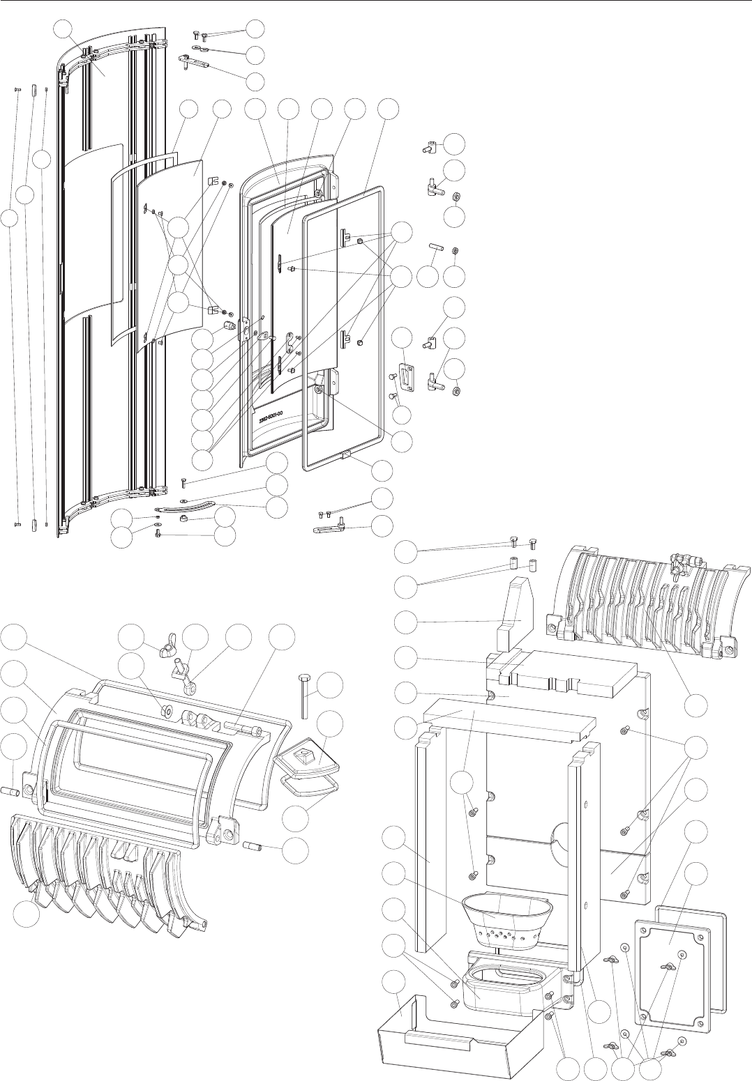
Spare part overview exploded diagram ............................................................................................................................................................4
Spare part overview article numbers ....................................................................................................................................................................7
Amount of Fuel .......................................................................................................................................................................................................................... 8
Technical data ...........................................................................................................................................................................................................................8
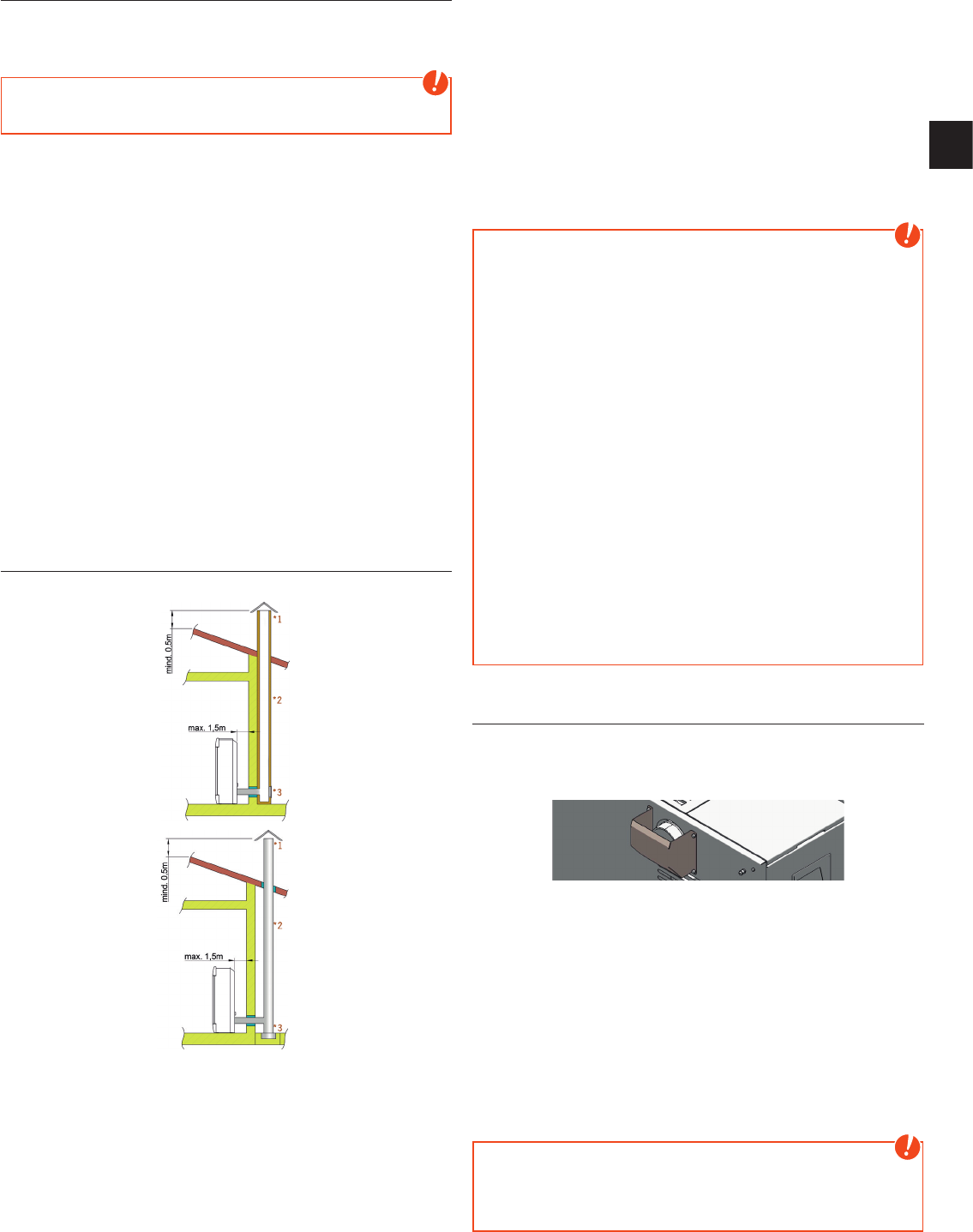
Connection to the chimney ........................................................................................................................................................................................... 9
Connecting to a steel chimney ..................................................................................................................................................................................9
Combustion air ......................................................................................................................................................................................................................... 9
Feeding in external combustion air ....................................................................................................................................................................... 9
3. IMPORTANT INFORMATION 10
General warning and safety information .......................................................................................................................................................10
First heating ...............................................................................................................................................................................................................................10
Prior to set up .............................................................................................................................................................................................................................11
The correct chimney connection .............................................................................................................................................................................11
Convection air conduction ............................................................................................................................................................................................11
4. BRIEF INFORMATION ON FUEL PELLETS 12
What are pellets? ....................................................................................................................................................................................................................12
Wood pellet specification according to ENplus – A1 .............................................................................................................................12
Pellet container refilling during operation ...................................................................................................................................................... 12
Top efficiency - lowest emissions ...........................................................................................................................................................................13
DAR - Dynamic Air Regulation ..................................................................................................................................................................................13
Electrical excess current protection ...................................................................................................................................................................13
Auger motor monitoring .................................................................................................................................................................................................13
Power failure (during heating) ..................................................................................................................................................................................13
Power failure (during the initial stage) ..............................................................................................................................................................13
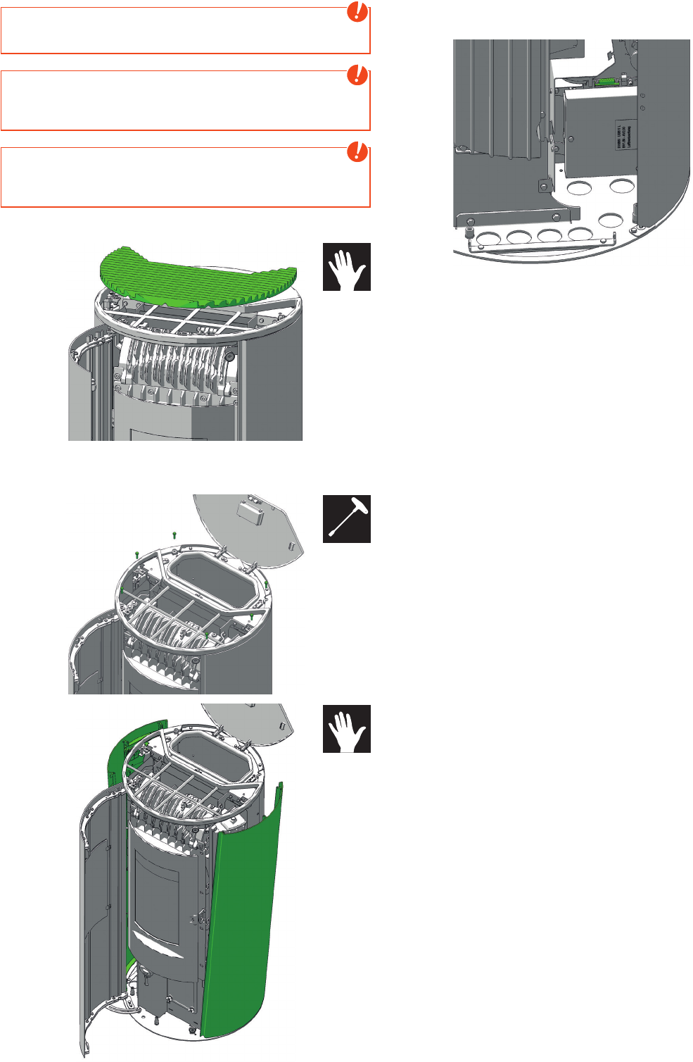
6. ASSEMBLY DISASSEMBLY SIDE PANELS 14
7. COMFORT OPTIONS 15
Room sensor, Radio room sensor ............................................................................................................................................................................15
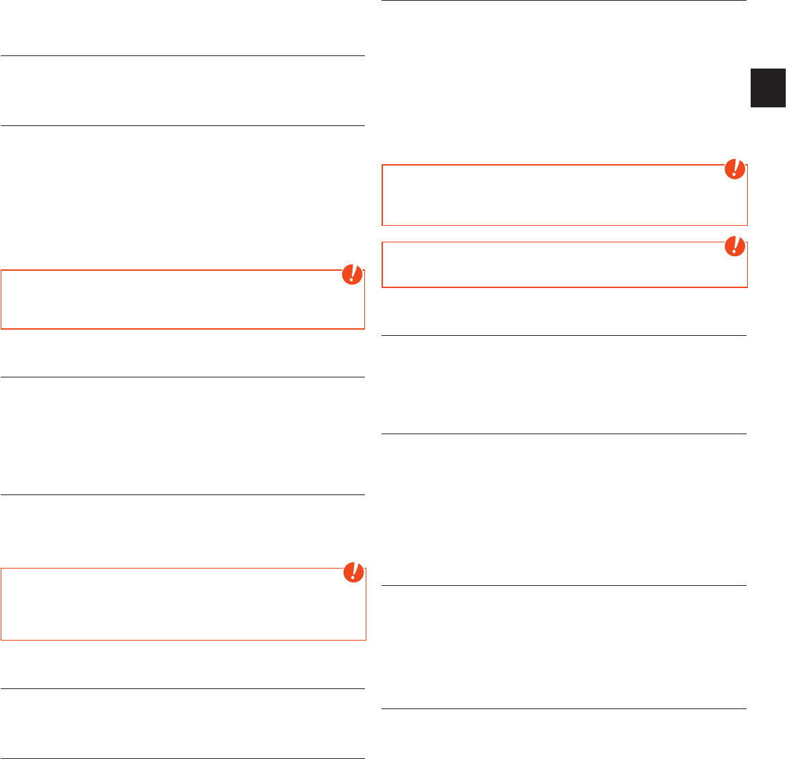
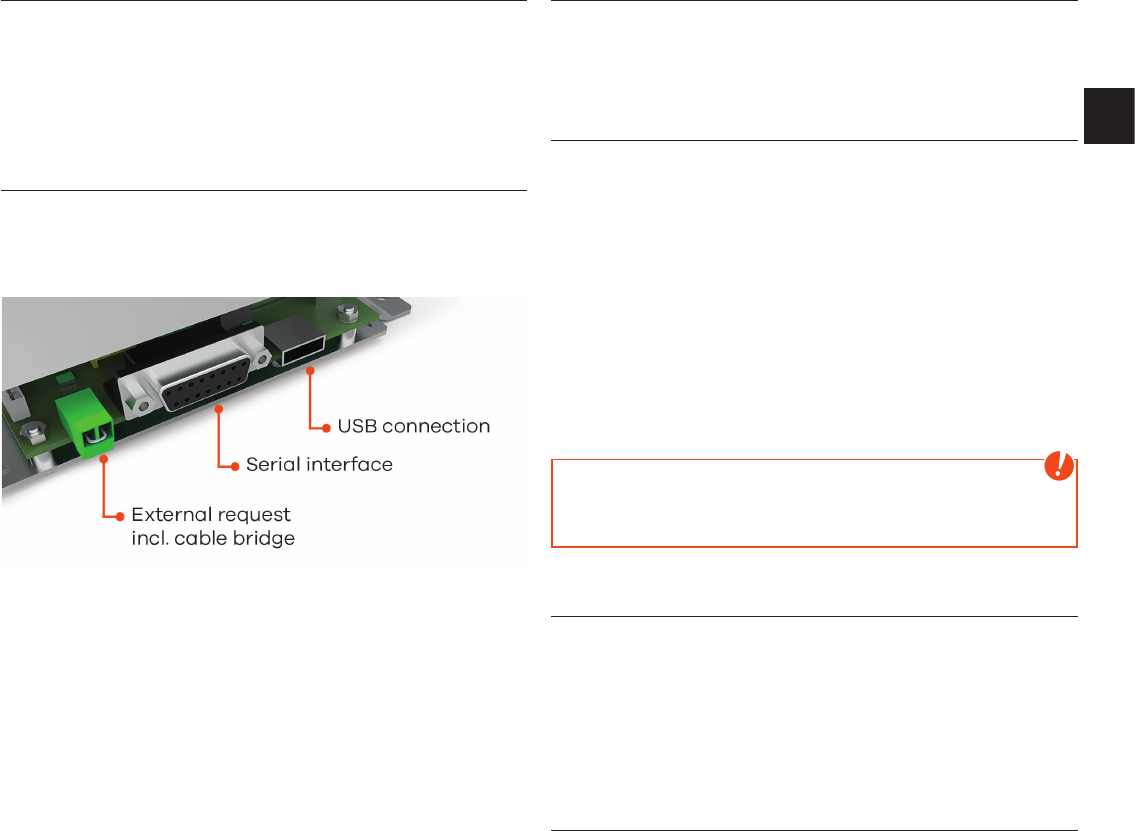
Interface for various options .......................................................................................................................................................................................15
Open the combustion chamber door ................................................................................................................................................................16
Empty the ash drawer ...................................................................................................................................................................................................... 16
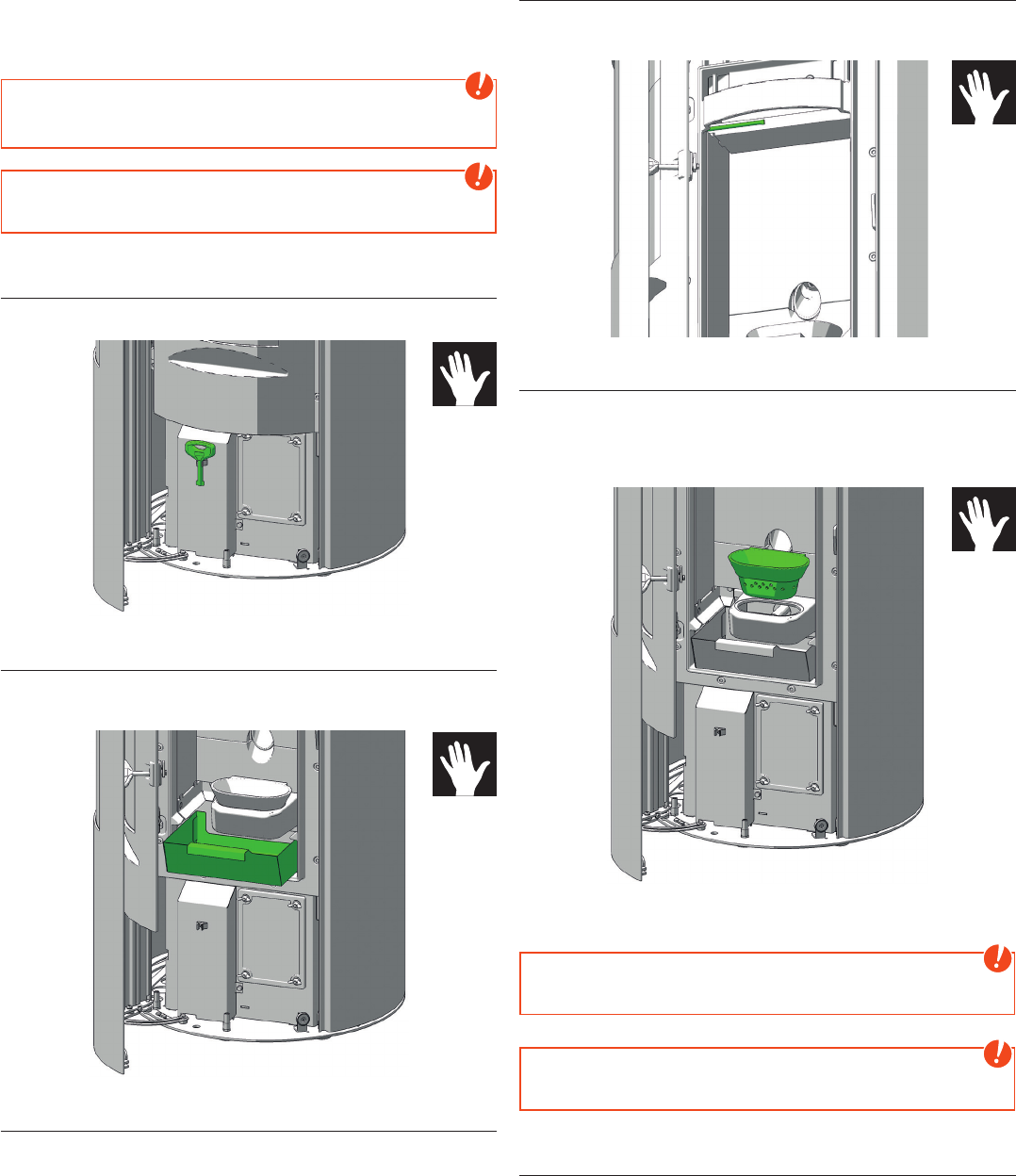
Cleaning the flame temperature sensor .........................................................................................................................................................16
Cleaning of the burn pot - daily ..............................................................................................................................................................................16
Cleaning the door glass ..................................................................................................................................................................................................16
9. CLEANING 17
Cleaning the convection air openings ...............................................................................................................................................................17
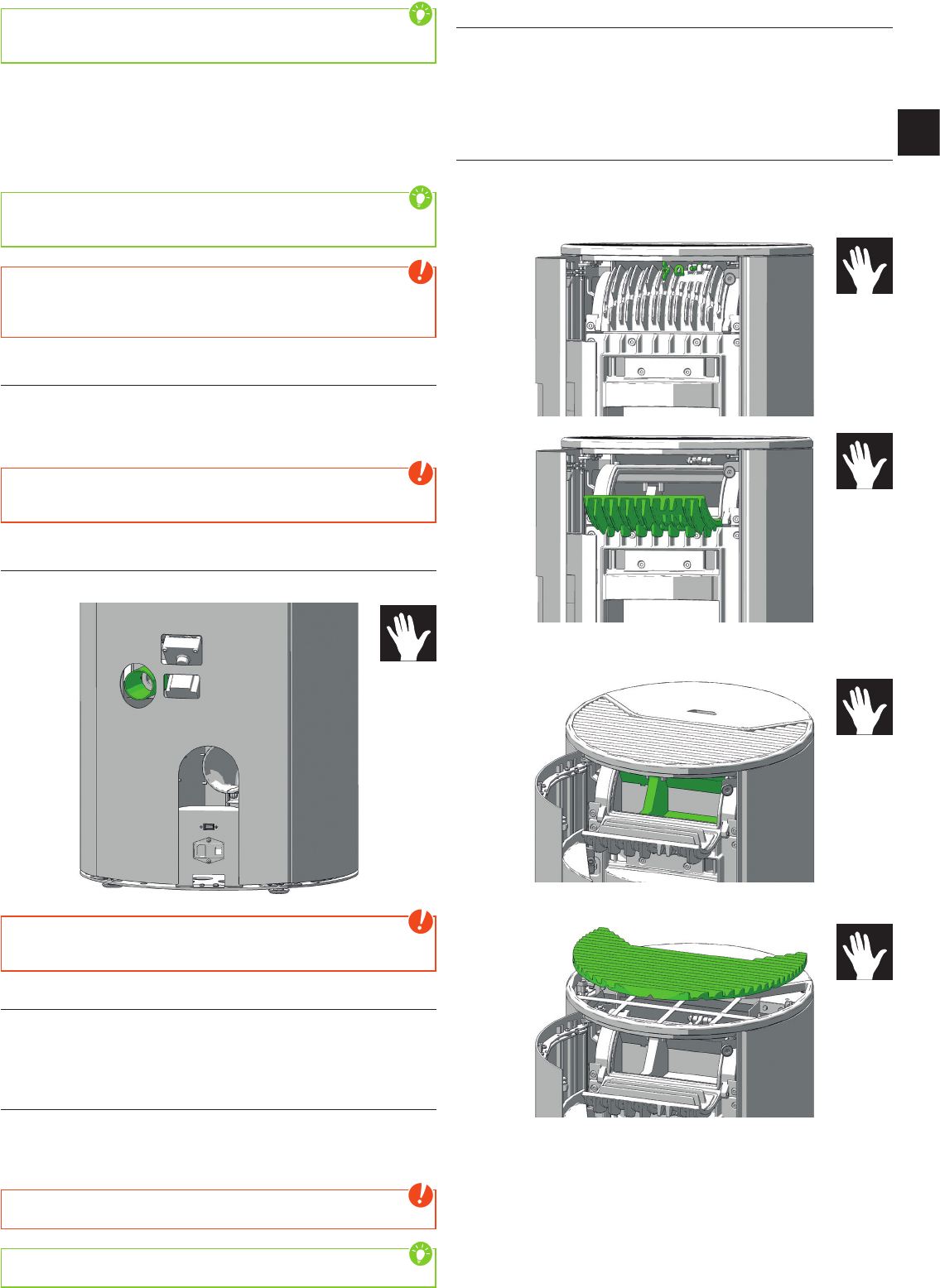
Combustion air - intake ...................................................................................................................................................................................................17
Cleaning the pellet container ..................................................................................................................................................................................... 17
Cleaning the flue gas channels and flue gas collecting duct ......................................................................................................17
Cleaning the flue pipes ................................................................................................................................................................................................... 18
10. PROBLEMS POSSIBLE SOLUTIONS 19
Problem 1 .......................................................................................................................................................................................................................................19
Problem 2 ......................................................................................................................................................................................................................................19
Problem 3 ..................................................................................................................................................................................................................................... 19
RIKA Innovative Ofentechnik, 4563 Micheldorf, Müllerviertel 20, Austria, hereby confirms that the provided personal data is exclusively used for in-house purposes, processing
and recording. The client confirms the reception of correct and clear instructions. Our general terms and conditions shall apply.
I consent to the collection, saving and use of my personal data (name, address, e-mail) by RIKA Innovative Ofentechnik GmbH for marketing and information purposes.
This consent can be withdrawn at any time and without any charge and formless under marketing@rika.at.
ATTENTION:
Compliance with national regulations and laws as well as locally applicable rules and regula-
tions is within the responsibility of the specialist contractor commissioned with installation.
22
12. GUARANTEE CONDITIONS
We recommend having the installation performed by a RIKA-certified technician.
These guarantee conditions only apply for the European mainland. For all other countries, the separate conditions of the
importer in the respective country apply. In cases of doubt, or in the case of missing or incorrect translations, the German
version is always the sole valid version.
In the interest of ensuring damage limitation in good time, the guarantee claim should be sent in writing to the RIKA specialist
or contract dealer.
In this event, the following documents must be presented:
• Written reason for complaint
• Invoice
• Installation record
• Model name and serial number
RIKA GUARANTEE
5 YEARS
on the welded stove body.
Up to 5 years or 10,000 kg of consumed pellets for pellet stoves.
This relates exclusively to defects in the material and processing, and to the supply of replacement parts free of charge.
Working hours and travel times are not covered by the manufacturer’s guarantee.
The guarantee is conditional on the following:
• Only original parts supplied by the manufacturer must be used.
• Professional installation of the stove in compliance with the respective operating manual valid at the time of purchase.
• The stove must be connected by a professional certified for that type of stove.
• The installation is performed by a RIKA-certified technician.
If these points are not complied with, the guarantee claim is void!
Any costs incurred by the manufacturer as a result of an unjustified guarantee claim will be charged back to the claimant.
Likewise excluded from the guarantee is any damage resulting from or caused by non-compliance with the manufacturer‘s
instructions for operating the appliance, e.g. overheating, use of non-approved fuels, unprofessional interference with
the appliance or the flue pipe, a flue suction that is incorrectly adjusted to the appliance or is insufficient or too strong,
condensation water, non-performance of or inadequate maintenance or cleaning, non-compliance with the applicable
building regulations, improper operation by the operator or third parties, transport and handling damage.
STATUTORY WARRANTY PROVISIONS REMAIN UNAFFECTED BY THE GUARANTEE!
13. WARRANTY CONDITIONS
See the respective general terms and conditions of business and warranty conditions of the RIKA dealer.
The warranty does not cover:
1. Wearing parts (normal wear and tear not resulting from a defect)
2. Parts in contact with fire, e.g. glass, combustion troughs, grates, baffle plates, deflectors, combustion chamber cladding
(e.g. refractory clay), ceramics, ignition elements, sensors, combustion chamber sensors and temperature monitors
Gebruikershandleiding.com neemt misbruik van zijn services uitermate serieus. U kunt hieronder aangeven waarom deze vraag ongepast is. Wij controleren de vraag en zonodig wordt deze verwijderd.
Product:
Spelregels forum
Om tot zinvolle vragen te komen hanteren wij de volgende spelregels:
lees eerst de handleiding door;
controleer of uw vraag al eerder door iemand anders is gesteld;
probeer uw vraag zo duidelijk mogelijk te stellen;
heeft u een probleem en al geprobeerd om dit op te lossen, vermeld dit erbij aub;
heeft u een oplossing gekregen van een bezoeker dan horen wij dat graag in dit forum;
wilt u een reactie geven op een vraag of antwoord, gebruik dan niet dit formulier maar klik op de knop 'reageer op deze vraag';
uw vraag wordt direct op de website gezet; vermijd daarom persoonlijke gegevens in te vullen;
Belangrijk! Als er een antwoord wordt gegeven op uw vraag, dan is het voor de gever van het antwoord nuttig om te weten als u er wel (of niet) mee geholpen bent! Wij vragen u dus ook te reageren op een antwoord.
Belangrijk! Antwoorden worden ook per e-mail naar abonnees gestuurd. Laat uw emailadres achter op deze site, zodat u op de hoogte blijft. U krijgt dan ook andere vragen en antwoorden te zien.
Abonneren
Abonneer u voor het ontvangen van emails voor uw Rika Cosmo bij:
nieuwe vragen en antwoorden
nieuwe handleidingen
U ontvangt een email met instructies om u voor één of beide opties in te schrijven.
Ontvang uw handleiding per email
Vul uw emailadres in en ontvang de handleiding van Rika Cosmo in de taal/talen: Engels als bijlage per email.
De handleiding is 8,76 mb groot.
U ontvangt de handleiding per email binnen enkele minuten. Als u geen email heeft ontvangen, dan heeft u waarschijnlijk een verkeerd emailadres ingevuld of is uw mailbox te vol. Daarnaast kan het zijn dat uw internetprovider een maximum heeft aan de grootte per email. Omdat hier een handleiding wordt meegestuurd, kan het voorkomen dat de email groter is dan toegestaan bij uw provider.
Uw handleiding is per email verstuurd. Controleer uw email
Als u niet binnen een kwartier uw email met handleiding ontvangen heeft, kan het zijn dat u een verkeerd emailadres heeft ingevuld of dat uw emailprovider een maximum grootte per email heeft ingesteld die kleiner is dan de grootte van de handleiding.
Er is een email naar u verstuurd om uw inschrijving definitief te maken.
Controleer uw email en volg de aanwijzingen op om uw inschrijving definitief te maken
U heeft geen emailadres opgegeven
Als u de handleiding per email wilt ontvangen, vul dan een geldig emailadres in.
Uw vraag is op deze pagina toegevoegd
Wilt u een email ontvangen bij een antwoord en/of nieuwe vragen? Vul dan hier uw emailadres in.