536366
13
Verklein
Vergroot
Pagina terug
1/114
Pagina verder
( Manual
3D-Printer Construction Kit RF1000
Item No. 1007507
3D-Printer RF1000
Item No. 1007508
2
Table of Contents
(
Page
1. Introduction ................................................................................................................................................................................................... 3
2. Explanation of Symbols ...............................................................................................................................................................................
4
3. Intended Use .................................................................................................................................................................................................
4
4. Safety Information ........................................................................................................................................................................................
4
5. Features .....................................................................................................................................................................................................
6
6. Working Principle of the 3D Printer ..........................................................................................................................................................
6
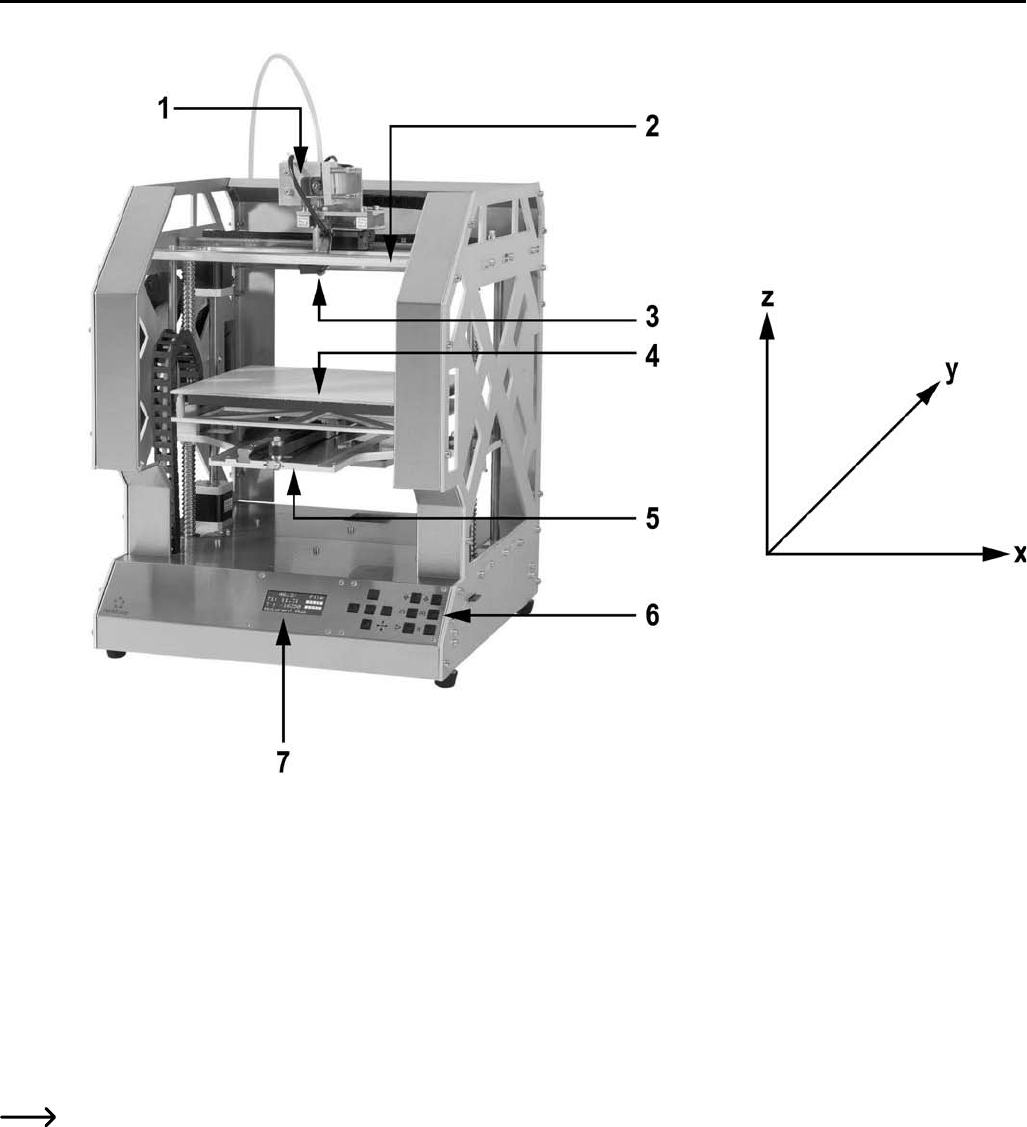
7. Overview of the Most Important Parts .....................................................................................................................................................
7
8. Required Tools and Material ......................................................................................................................................................................
8
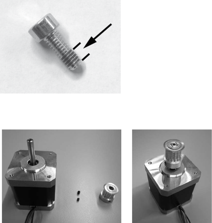
9. Assembly of the Mechanical Parts ...........................................................................................................................................................
8
a) General .................................................................................................................................................................................................... 8
b) Assembly of the Components .............................................................................................................................................................
9
10. Wiring of the Electrical Components ......................................................................................................................................................
40
a) General .................................................................................................................................................................................................. 40
b) Wiring of the Components ..................................................................................................................................................................
41
c) Installation of the PCBs ......................................................................................................................................................................
49
11. Final Work ....................................................................................................................................................................................................
54
12. Initial Commissioning .................................................................................................................................................................................
57
a) Assembly of the Filament Holder and the Filament Hose .............................................................................................................
57
b) Insertion of the Filament .....................................................................................................................................................................
58
c) Setup and Transport ............................................................................................................................................................................
59
d) Mains Connection and First Activation ............................................................................................................................................
59
e) Calibration ............................................................................................................................................................................................. 60
f) First Print of an Example Object from the SD Card ........................................................................................................................
63
13. Operation at the Printer .............................................................................................................................................................................
65
a) Menu Overview ....................................................................................................................................................................................
65
b) Functions of the Individual Menu Items ...........................................................................................................................................
67
14. General Notes on 3D Printing ...................................................................................................................................................................
69
15. Software “Repetier Host” .........................................................................................................................................................................
70
a) General Notes on Software ...............................................................................................................................................................
70
b) Installation ............................................................................................................................................................................................ 70
c) Connection of the Connected Printer ...............................................................................................................................................
71
d) Manual Operation via the Software .................................................................................................................................................
73
e) Placement of a printing Object in the Software .............................................................................................................................
74
f) Preparation for Print ............................................................................................................................................................................
76
g) Printing .................................................................................................................................................................................................. 78
h) More Detailed Description of the Slicer Functions ........................................................................................................................
80
16. Software “Cura” .........................................................................................................................................................................................
86
a) General Notes on Software ...............................................................................................................................................................
86
b) Installation ............................................................................................................................................................................................ 86
c) Setup of the Software .........................................................................................................................................................................
87
d) Use of the Software in the Quickprint Mode ...................................................................................................................................
91
e) Use of the Software in the Expert Mode ..........................................................................................................................................
92
17. Filament Change .........................................................................................................................................................................................
94
18. Firmware Update ........................................................................................................................................................................................
95
3
Page
19. Maintenance ............................................................................................................................................................................................... 97
a) General .................................................................................................................................................................................................. 97
b) Cleaning ................................................................................................................................................................................................. 98
c) Fuse Replacement ...............................................................................................................................................................................
98
d) Checking the Belt Tension ..................................................................................................................................................................
98
e) Nozzle Change ....................................................................................................................................................................................
101
20. Handling ..................................................................................................................................................................................................... 101
21. Troubleshooting ........................................................................................................................................................................................ 102
22. Disposal ..................................................................................................................................................................................................... 104
23. Technical Data ..........................................................................................................................................................................................
104
24. Annex ......................................................................................................................................................................................................... 105
a) Wiring Plan of the Main PCB ...........................................................................................................................................................
105
b) Notes on the Print Files (GCODE Files) on the Enclosed SD Card .............................................................................................
106
c) Setting up the Printer Settings ........................................................................................................................................................
106
d) Explanation on the Configuration Files on the Enclosed SD Card .............................................................................................
109
e) Setting up the Slicer ..........................................................................................................................................................................
109
f) Recommended Tightening Torque of the Screws ........................................................................................................................
112
1. Introduction
Dear Customer,
thank you for purchasing this product.
This product complies with the statutory national and European specifications. To maintain this status and to ensure safe operati
-
on, you as the user must observe these operating instructions!
These operating instructions are part of this product. They contain important notes on commissioning and handling. Also
consider this if you pass on the product to any third party. Therefore, retain these operating instructions for reference!
If there are any technical questions, please contact:
International:
www.conrad.com/contact
United Kingdom: www.conrad-electronic.co.uk/contact
4
2. Explanation of Symbols
The symbol with a lightning bolt in a triangle is used where there is a health hazard, e.g. from electric shock. The device
contains no parts that require servicing by the user. Therefore, never open the device.
The exclamation mark symbol indicates that the user must read these operating instructions before commissioning of
the device, and observe them during operation.
This symbol warns of hot surfaces the contact with which may cause injury.
This symbol warns of hand injury that may occur when reaching into the device in operation.
The symbol with the arrow indicates special advice and notes.
3. Intended Use
The 3D printer produces 3D-objects from suitable printing files. For this, suitable raw material (filament) is melted in the print head
and attached in the required position for the object.
This product is only approved for connection to 100-240 V/50/60 Hz alternating current
.
It is intended for indoor operation only. Do not use it outdoors. Contact with moisture, e.g. in bathrooms, must be avoided under
all circumstances.
Any use other than that described above will damage this product and involves the risk of short circuit, fire, electric shock, etc.
This product complies with the statutory national and European requirements. All company names and product names are trade
-
marks of their respective owners. All rights reserved.
ATTENTION Mains voltage - the connection, installation and wiring of the electrical components must only be perfor
-
med by an electrician who is familiar with the applicable safety provisions. Before commissioning, inspection accor-
ding to the applicable safety provisions must be performed by an electrician.
Observe all safety and assembly notes in these operating instructions!
4. Safety Information
The guarantee/warranty will expire if damage is incurred resulting from non-compliance with these operating instruc-
tions. We do not assume liability for any consequential damage.
Nor do we assume any liability for damage to property or personal injury caused by improper use or failure to observe
the safety information. In such cases the warranty/guarantee is voided.
Dear Customer: The following safety information is intended not only for the protection of the device but also for the
protection of your health. Please read through the following attentively:
For safety reasons, any unauthorized conversions and/or modifications to the product deviating from these operating
instructions are not permitted. Components may be damaged and thus impair the function or safety of the device.
When setting up the 3D printer, observe that the mains switch at the rear of the device must be easy to reach so that
the device can be switched o quickly and easily in case of malfunction.
5
Never reach into the 3D printer in operation. The mechanically moved parts within the printer pose a high risk of inju-
ry!
The print head and the heating plate grow very hot in operation. Never touch these parts during or just after operation.
Let them cool down suciently first (approx. 60 minutes).
The
mains unit corresponds to the applicable CE provisions. Compliance with the applicable CE provisions for the
finished construction kit, whoever, is subject to the constructor of the construction kit and also essentially depends on
precise work during assembly.
All persons who operate this product, mount, install, assemble it, put it into operation or service it must be trained and
qualified accordingly and must observe these operating instructions.
Disconnect the device from the mains before maintenance work or modifications (unplug the mains plug) and let it
cool down.
In operation, there will be noise and, depending on the filament material used, smells. Observe this when selecting
the site of setup and the filament material. Ensure sucient ventilation or install an extraction system. Do not inhale
arising vapours. When using any other than the recommended filament material, poisonous vapours or gases may
develop.
The 3D printer is not suitable for persons with physical, sensor or metal limitations or for inexperienced or uninformed
persons.
This product is not a toy and not suitable for children. Children cannot judge the dangers involved when handling
electrical devices.
This
device is a safety class 1 product. The only permissible voltage source is a properly grounded mains socket
(100-240 V/50/60 Hz) of the public mains.
The devices must not be exposed to any extreme temperatures, strong vibrations, high moisture, such as rain or steam
or strong mechanical strain.
Never place containers containing liquids, e.g. glasses, vases, etc. on the device or in its vicinity and do not pour any
liquids out over the device. Liquids may get into the housing and impair electrical safety. This also poses great danger
of fire or potentially fatal electric shock!
If this is the case, first power down the respective mains socket on all poles (e.g. switch o circuit breaker and FI
switch) and then pull the mains cable from the socket. Disconnect all lines from the device. Do not operate any part of
the product anymore afterwards, but take it to a specialist workshop.
Never
place any sources of open fire, such as lit candles, on or right next to the device.
Do not touch the mains cable if it is damaged. First power down the respective mains socket on all poles (e.g. switch
o circuit breaker and FI switch) and then pull the mains cable from the socket. Never operate the product with a
damaged mains line.
When setting up the product, make sure that the mains cable is not pinched or damaged by sharp edges.
Never
touch the mains line or the mains plug with wet or damp hands. There is a risk of potentially fatal electric
shock!
The mechanical parts of the product are produced highly precisely. Never apply any mechanical force here. The
3D printer may be rendered useless by this.
Never operate the device unattended.
Only
operate the device in moderate climates, never in tropical climates.
Do not leave any packaging material unattended. It may become a dangerous toy for children.
If you are not sure of the correct connection or if there are any questions that are not covered by the operating instruc
-
tions, do not hesitate to contact our technical support or another specialist.
Also observe the additional safety information in the individual chapters of these instructions.
6
5. Features
Large printing space of approx. 245 x 230 x 200 mm
Play-free profile rail guides and ball-threaded drives for maximum precision
Automatic printing plate measurement
Ceramics
heating plate with structural surface
Highly precise extruder with replaceable printing nozzle
Integrated long-lived industrial mains unit
Display and key pad for the device operation right at the device
Control via a computer (USB) or stand-alone operation (with SD or SDHC card) possible
Manual control of the printing parameters possible even during operation
Extremely
stable by aluminium/steel mechanics
Suitable for all common standard roll filament types
Breaking and abrasion-free cable guides across energy guide chains
Future-proof with optional accessories
6. Working Principle of the 3D Printer
For 3D print, first a file is needed that contains the three-dimensional data of the object to be printed (a common format of such a
file is, e.g., a .stl-file).
This file can be produced with the corresponding software or with a 3D-scanner. There are also many printing files already online
that can be downloaded to print an object as quickly as possible.
The actual printer software has the task to render the above three-dimensional file into a file that the printer can print. This is a
file in which the individual print layers, the print temperatures for printing head and heating bed, etc. are specified. The file has
the extension “.gcode”.
This GCODE printing file is sent to the 3D printer either via the USB interface by the computer, or an SD card with the printing file
is put into the card reader and the 3D printer is used in standalone operation.
The 3D printer then prints the print file layer for layer according to the FFF (Fused Filament Fabrication) / FDM (Fused Deposition
Modelling) procedure.
At the actual print, the filament material is transported from the filament roll to the print head (extruder).
In the extruder, the filament material is melted and then applied to the heating plate via a fine extruder nozzle layer by layer.
The heating plate moves in the Y and Z directions, the extruder moves in the X-direction. Thus, all prerequisites to produce a three-
dimensional object by horizontal application of the present layers are created.
A 3D printer is a highly complex device in which many parameters must be set depending on the printer, printed object
and filament material used.
Additionally, the adhesion of the printed object on the printing plate is influenced by printing plate temperature, fila
-
ment material, shape of the printed object and surface properties of the printing plate.
Ambience influences such as drafts, grease on the printing plate, etc. also play a role in the quality and adhesion of the
printed object.
For the above reasons, it is not possible to achieve high-quality print results at once and without previous experi
-
ments.
Change the adjustable parameters in small steps to achieve the best printing results for your application. The printing
examples enclosed on the SD-card provide references, but must be refined for perfect results depending on the above
parameters.
7
7. Overview of the Most Important Parts
(1) Extruder carriage
(2) X-plate
(3) Extruder
(4) Heating plate
(5) Y-plate
(6) Operating button field
(7) Display
To the right of the figure, the printing directions (x, y and z) are indicated.
8
8. Required Tools and Material
Dierent screwdrivers (cross-head and slotted)
Hexagon socket wrench 1.5 mm / 2 mm / 2.5 mm / 3 mm / 4 mm
Hexagon wrench 4 mm / 5 mm / 5.5 mm / 7 mm / 13 mm (2x)
Stop
angle
Calliper
Wire cutter
Small flat pliers and small long-nose pliers
Threadlocker
varnish, medium strength
Hot-glue gun (optional)
9. Assembly of the Mechanical Parts
The following chapters refer to the assembly of the 3D printing construction kit, but are also interesting for owners of the ready-
made device as information for later accessory assembly.
If you have purchased the finished device, you can skip the following chapters and continue directly with the chapter “Initial
commissioning”.
a) General Information
Take enough time for the assembly. Hurrying often leads to mistakes that may damage components or ruin the time
benefit by elaborate rework.
The workplace should be suciently large and clean so that the dierent components and assemblies can be put down
and installed easily.
The
stainless steel parts of the construction kit are very sensitive to dirt. Wash your hands before installing these parts
and use cotton gloves if necessary. Remove the protective film only directly before assembly.
Always observe the images during assembly. Here, the assembly locations and correct alignment of the components
are shown.
All mechanical components of the construction kit are produced extremely precisely. Never apply any force during as
-
sembly. All parts can be assembled without any great application of force. If this is not the case, rethink the assembly
step and reread the corresponding description in these instructions.
When tightening the screws, ensure that you do not tighten them too tightly. Many screws are turned into aluminium
threads and therefore must not be tightened as far as it would be possible, e.g., in steel threads. A table with the re-
commended tightening torques of the screws can be found in the appendix of these instructions.
Sort the screws by size before assembly. This facilitates assembly, since you do not have to look for individual screws.
For
countersunk-head screws, the length (l) is measured with the screw head; for cylinder head screws, the length
measurement takes place without the screw head. The diameter (d) is always measured by the thread.
9
Application of the threadlocker varnish
In the following instruction, some screws must be secured with threadlocker varnish. This is indicated accordingly in the text.
Procedure:
Put a small drop of threadlocker varnish medium-strength onto the thread start. Observe that you must only use a small drop as
shown in the following screen.
b) Assembly of the Components
Attachment of the motor pinion to the actuators
3x actuator
3x
sprocket 14Z (small pinion, outer dia. 16 mm)
6x threaded pin M3 x 5
Push sprockets onto axes of the actuators and attach them
with 2 threaded pins each. Apply threaded pins with thread
-
locker varnish.
The
motor axes must end flush with the upper edges of the
sprockets.
10
Assembly of the bottom plate
Assembly of the belt tensioner
1x bottom plate
1x
belt tensioner basic body
3x ball bearing 624ZZ (diameter inside/outside (8.8/13 mm)
4x washer (diameter inside/outside 4.3/8.8 mm)
1x
cylinder head screw M4x30
1x cylinder head screw M5x70
1x nut M4
Insert belt tensioner basic body into the intended breakout of
the bottom plate. The cross-bore of the belt tensioner basic
body and the bore in the bottom plate must align.
Push
washers onto the M4x30 screw alternatingly with the ball
bearings.
Screw the screw equipped in this manner, as shown in the fig-
ure, into the belt tensioner basic body and tighten it well.
Counter
the screw with the nut at the belt tensioner basic body
(in the figure on the bottom of the bottom plate).
The screw head of the belt tensioner (on the right in the figure)
is supported against the housing side part to be installed later
so that the belt tensioner function is only present after assem
-
bly of the side part
Assembly
of the Spacers
4x spacers
1x bottom plate
4x cylinder head screw M5x16
Turn
the bottom plate and attach the spacers to the top of the
bottom plate with the screws as shown.
11
Assembly of the drive motor
1x actuator
1x
bottom plate
4x cylinder head screw M3x12
Attach the actuator to the bottom plate with the 4 screws as
shown in the figure.
Apply screws with threadlocker varnish.
The cable exit of the actuator must point at the long side of the
plate as shown.
Inserting the grooved ball bearings
2x grooved ball bearings
1x
bottom plate
Insert
the grooved ball bearings into the corresponding bores
of the bottom plate from above.
Turn the grooved ball bearings slightly, when inserting them
into the bores. Do not apply any force. The flanges of the
grooved ball bearings must be cleanly aligned with the top of
the bottom plate.
12
Assembly of the X plate
Assembly of belt tensioner
1x belt tensioner basic body
3x
ball bearing 624ZZ (diameter inside/outside (8.8/13 mm)
4x washer (diameter inside/outside 4.3/8.8 mm)
1x cylinder head screw M4x30
1x
nut M4
Push washers onto the screw with the ball bearings alternat
-
ingly.
Screw the screw into the belt tensioner basic body as shown
in the figure and tighten it well.
Counter the screw with a nut.
Attachment of belt tensioner to the X-plate
1x X-plate
1x assembly belt tensioner (see above)
1x cylinder head screw M4x30
Push
the belt tensioner assembly into the intended section of
the X-plate and turn the screw into the belt tensioner.
Observe the position of the bore in the belt tensioner (must be
on the right as shown in the figure). The ball bearings must be
on the grooved side of the X-plate.
13
Attachment of the guide rail
1x X-plate
1x
guide rails
6x cylinder head screws M4x12
Insert the guide rail into the middle groove of the X-plate and
attach with the screws.
The imprinted arrows on the guide rail must point to the side of
the belt tensioner.
Push the guide carriage onto the guide rail
The assembly aid (plastic part in the guide of the guide carriage) must never be removed before pushing on the guide
carriage, since the gearing balls will fall out of the carriage otherwise. This would be irreparable.
This also applies when the guide carriage is pushed from the guide rail after assembly. For reasons of safety, the guide
carriage should be secured, e.g. with adhesive tape before further installation.
The guide carriage has a polished area on one side (see arrow in the figure on the lower left). Turn the guide carriage
so that the arrows on the guide rails point towards the ground area of the guide carriage before pushing it on.
13

Hulp nodig? Stel uw vraag in het forum

Spelregels
1

Forum

Renkforce-RF1000
  • ik heb een nieuw bed gemonteerd en ben bezig met kalibreren. Wat moet ik doen als ik het bericht krijg "heat bed scan aborteer" Gesteld op 28-4-2020 om 17:23

    Reageer op deze vraag Misbruik melden

Misbruik melden

Gebruikershandleiding.com neemt misbruik van zijn services uitermate serieus. U kunt hieronder aangeven waarom deze vraag ongepast is. Wij controleren de vraag en zonodig wordt deze verwijderd.

Product:

Bijvoorbeeld antisemitische inhoud, racistische inhoud, of materiaal dat gewelddadige fysieke handelingen tot gevolg kan hebben.

Bijvoorbeeld een creditcardnummer, een persoonlijk identificatienummer, of een geheim adres. E-mailadressen en volledige namen worden niet als privégegevens beschouwd.

Spelregels forum

Om tot zinvolle vragen te komen hanteren wij de volgende spelregels:

Belangrijk! Als er een antwoord wordt gegeven op uw vraag, dan is het voor de gever van het antwoord nuttig om te weten als u er wel (of niet) mee geholpen bent! Wij vragen u dus ook te reageren op een antwoord.

Belangrijk! Antwoorden worden ook per e-mail naar abonnees gestuurd. Laat uw emailadres achter op deze site, zodat u op de hoogte blijft. U krijgt dan ook andere vragen en antwoorden te zien.

Abonneren

Abonneer u voor het ontvangen van emails voor uw Renkforce RF1000 bij:


U ontvangt een email met instructies om u voor één of beide opties in te schrijven.


Ontvang uw handleiding per email

Vul uw emailadres in en ontvang de handleiding van Renkforce RF1000 in de taal/talen: Engels als bijlage per email.

De handleiding is 8,67 mb groot.


U ontvangt de handleiding per email binnen enkele minuten. Als u geen email heeft ontvangen, dan heeft u waarschijnlijk een verkeerd emailadres ingevuld of is uw mailbox te vol. Daarnaast kan het zijn dat uw internetprovider een maximum heeft aan de grootte per email. Omdat hier een handleiding wordt meegestuurd, kan het voorkomen dat de email groter is dan toegestaan bij uw provider.

Stel vragen via chat aan uw handleiding

Stel uw vraag over deze PDF

Andere handleiding(en) van Renkforce RF1000

Renkforce RF1000 Gebruiksaanwijzing - Deutsch - 104 pagina's


Uw handleiding is per email verstuurd. Controleer uw email

Als u niet binnen een kwartier uw email met handleiding ontvangen heeft, kan het zijn dat u een verkeerd emailadres heeft ingevuld of dat uw emailprovider een maximum grootte per email heeft ingesteld die kleiner is dan de grootte van de handleiding.

Er is een email naar u verstuurd om uw inschrijving definitief te maken.

Controleer uw email en volg de aanwijzingen op om uw inschrijving definitief te maken

U heeft geen emailadres opgegeven

Als u de handleiding per email wilt ontvangen, vul dan een geldig emailadres in.

Uw vraag is op deze pagina toegevoegd

Wilt u een email ontvangen bij een antwoord en/of nieuwe vragen? Vul dan hier uw emailadres in.


Info