Important Information Regarding Electromagnetic Interference (EMI) .........................................................................................3
Getting to know your Model 140T/140F .............................................................................................................................................6
Installing Seat and Front Basket .......................................................................................................................................................7
Front Basket Installation ....................................................................................................................................................................8
Figure 3 — Battery Charging, Off Vehicle ...................................................................................................................................9
Figure 4 — Battery Case Charging Connection.......................................................................................................................10
Controls and Adjustments.......................................................................................................................................................................11
LED Status Indicator............................................................................................................................................... 12
Using the 140T/140F....................................................................................................................................................................................18
Transferring On or Off the Vehicle................................................................................................................................................19
Curbs and Small Obstacles .....................................................................................................................................................21
Figure 11 — Brake Release Lever and Overload Fuse ...................................................................................................22
Figure 12 - Model 140F Disassembled ...........................................................................................................................................................24
Model 140T/140F Owner’s Manual
EMC Part: 44000700 • Rev. 02 • 04/19/06
iv
ELECTRIC
MOBILITY
Disassembling Your Model 140T/140F..........................................................................................................................................25
Figure 13 - Battery Case Removal...........................................................................................................................................................25
Figure 16 - Front Frame Assembly Detachment................................................................................................................................... 26
Re-assembling the Model 140T/140F...........................................................................................................................................27
Figure 17 - Aligning Front Frame Assembly to Rear Drivetrain Assembly......................................................................................27
Transporting Model 140T/140F..............................................................................................................................................................29
Maintenance and Servicing ......................................................................................................................................................................31
Motor Brakes......................................................................................................................................................................................33
Parts Ordering/Factory Return Procedures.......................................................................................................................................38
3Battery Charging, Off Vehicle...........................................................................................................................9
4Battery Case Charging Connection.............................................................................................................10
13Battery Case Removal.....................................................................................................................................25
17Aligning Front Frame Assembly to Rear Drivetrain Assembly...............................................................27
No liability is assumed with respect to the use of any information contained in this publication. While every precaution has been taken in the preparation of this
publication, Electric Mobilty Corp., assumes no responsibility for errors or omissions nor is any liability assumed for damagesresulting from the use of information
contained in this publication. This publication, as well as operational details described herein, are subject to change without notice.
Model 140T/140F Owner’s Manual
EMC Part: 44000700 • Rev.02 • 04/19/06
1
ELECTRIC
MOBILITY
Safety Information
Read and understand these Warnings and the entire manual before using your Model 140T/140F Scooter. Failure to follow
these instructions may result in damage to the vehicle or serious injury. NOTE: The caster wheels may NOT
prevent the scooter from tipping if scooter is used improperly.
1.DO NOT exceed the specifications of this unit, modify
this unit in anyway, or use the unit for a purpose other
than as intended.
2.DO NOT operate this unit if your health or
medications you are taking cause you to feel dizzy, affect
your vision, or in any way impact your thought process,
coordination, or ability to safely operate the unit.
Check with your physician should you experience any of
these symptoms.
3.DO NOT operate this unit after consuming any
alcoholic beverages.
4.DO NOT transfer “on” or “off” the unit until it is
turned “OFF”, completely stopped, and when it is on a
stable and level surface.
5.DO NOT attempt to ride over curbs or other
obstruction higher than 2 inches.
6.DO NOT stop when going up an incline. If you must
do so, always lean forward to shift the center of gravity
and prevent the unit from tipping.
7.DO NOT climb inclines that pose a concern for
stability.
WARNING!
This vehicle is not a medical device and is NOT intended for use by those with mobility problems or
medical disabilities.
Model 140T/140F Owner’s Manual
EMC Part: 44000700 • Rev.02 • 04/19/06
2
ELECTRIC
MOBILITY
8.DO NOT drive across an incline or attempt to turn
while on an incline.
9.DO NOT back down an incline or allow the unit to be
backed down an incline.
10.DO NOT turn off the power while the unit is moving.
11.ALWAYS remember vehicle capacity is limited to one
person only. This unit is not approved for towing or for
weights in excess of the published maximum.
12.ALWAYS drive straight up and down inclines.
13.ALWAYS turn the power off when the unit is not in
use. This will not only extend the life of the charge in
the battery but will keep the unit from being
accidentally moved.
14.ALWAYS use a grounded receptacle. Use of a non-
grounded receptacle could result in an electrical shock.
15.ALWAYS reduce speed when making a turn.
16.ALWAYS keep arms and legs within the confines of
the unit.
17.USE EXTRA CAUTION when climbing inclines
(ramps, hills, driveways, etc.).
18.USE CAUTION when braking on an incline or wet or
slippery surfaces as the unit will take longer to come to
a complete stop.
19.USE CAUTION when operating the unit in bad
weather or driving through water as moisture could
affect the control system or other parts of the unit
either temporarily or permanently.
20.OPERATOR must remain seated when the unit is
moving.
21.NEVER hose off your vehicle or allow it to come in
direct contact with water.
22.NEVER use your unit in a shower or steam room.
23.NEVER charge batteries that may be frozen.
Model 140T/140F Owner’s Manual
EMC Part: 44000700 • Rev.02 • 04/19/06
3
ELECTRIC
MOBILITY
Important Information Regarding Electromagnetic Interference (EMI)
It is very important that you read this information regarding the possible effects of electromagnetic interference (EMI) on
your scooter.
Electromagnetic interference (EMI) refers to the effects that outside sources of electromagnetic energy (radio and
television broadcasts, CB radios, garage door openers, cellular telephones, etc.) might have on the control systems of your
scooter. The interference from these sources could cause the scooter to release its brakes, move by itself, or to move in
an unintended direction. EMI could also result in permanent damage to the control system.
The sources of electromagnetic energy can be broadly classified into three types:
•Hand held short-range portable transceivers — These are transmitter/receivers with the antenna mounted
directly on the unit. Examples include: citizen band (CB) radios, “walkie-talkies”, security, fire and police transceivers,
cellular telephones, and devices that transmit signals even when not in use.
•Medium range mobile transceivers— These usually have the antenna mounted outside of a vehicle or building.
Examples include: police, fire, ambulance and taxi transceivers.
•Long range transmitters and receivers — These usually have the antenna mounted on a tower. Examples
include: commercial radio/television broadcasts and amateur (HAM) radios.
Model 140T/140F Owner’s Manual
EMC Part: 44000700 • Rev.02 • 04/19/06
4
ELECTRIC
MOBILITY
Other types of hand-held devices like cordless phones, laptop computers, AM/FM radios, and small appliances like hair
dryers or electric shavers may also generate electromagnetic energy, but it is such a small amount that, as far as we know,
no EMI problems should occur with these devices.
The intensity of interference from electromagnetic energy is measured in volts per meter (v/m), which refers to the
strength of the electrical source (voltage) as it relates to the distance away from the object being considered (in meters).
Resistance of a scooter to a certain EMI intensity is commonly called its “immunity level.” A level of 20 volts/meter is a
generally achievable and useful immunity level against interference from radio wave sources (the higher the immunity level,
the greater the protection).
Your scooter has been tested and found to meet the required immunity level for Electromagnetic Interference (20 v/m).
Model 140T/140F Owner’s Manual
EMC Part: 44000700 • Rev.02 • 04/19/06
5
ELECTRIC
MOBILITY
WARNING!
Even with an immunity level of 20 volt/meter, certain precautions must be followed
to ensure that your vehicle will not be affected by outside electromagnetic sources.
•Do not operate hand-held transceivers such as citizen band (CB) radios or turn on powered communication
devices such as cellular phones while the scooter is turned on.
•Be aware of nearby transmitters, such as radio and television stations, and avoid coming close to them.
•If an unintended movement should occur while operating the scooter, turn the power “off” as soon as it is safe to
do so.
•Be aware that if you do operate any electrically powered accessories, radios, cellular phones, or other devices, that
your scooter may become more susceptible to interference from outside electromagnetic sources.
•Report all incidents of unintended movement or unexpected brake releases to Electric Mobility’s customer service
department.
Model 140T/140F Owner’s Manual
EMC Part: 44000700 • Rev.02 • 04/19/06
6
ELECTRIC
MOBILITY
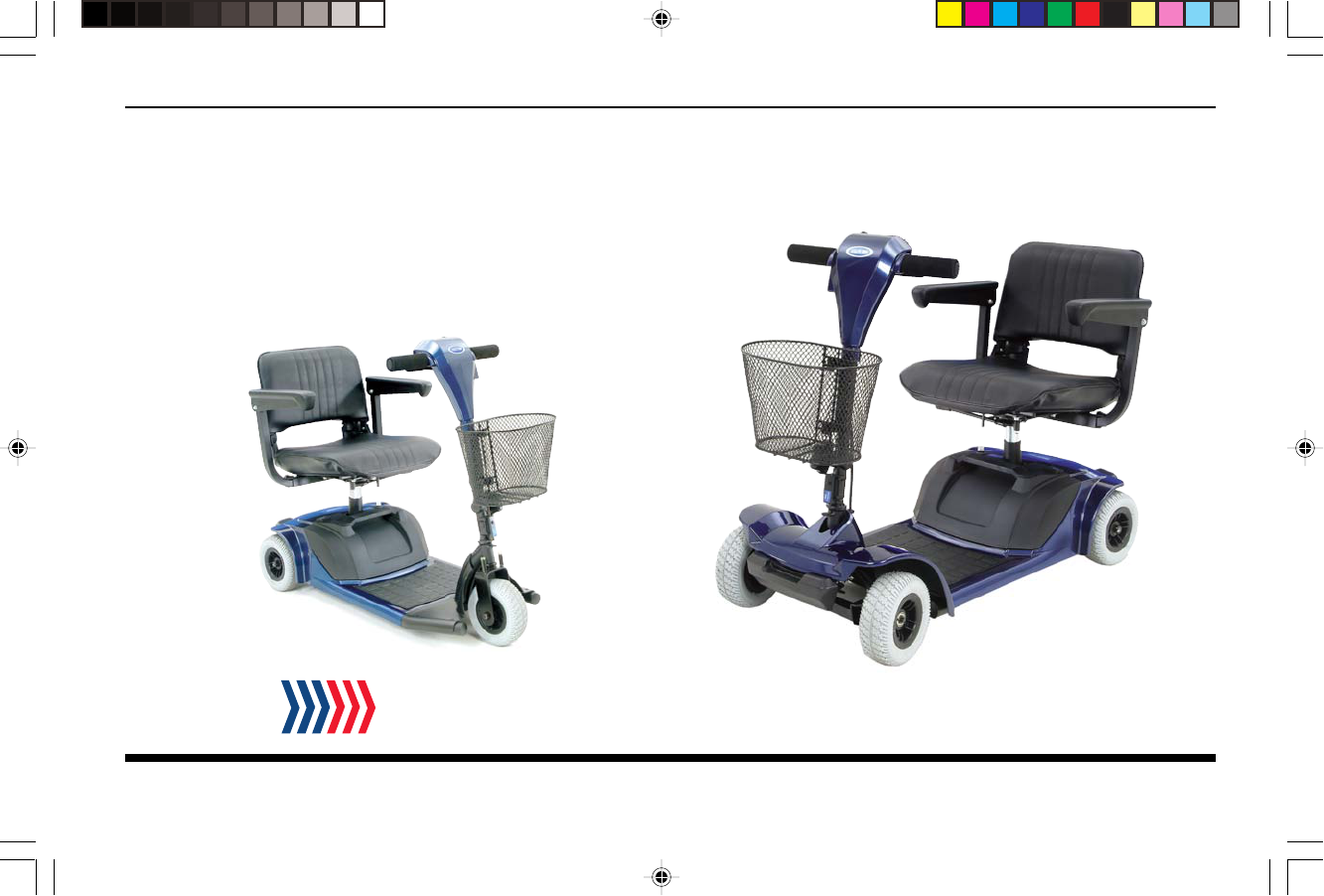
Getting to know your Model 140T/140F
Your Model140T/140F scooter from Electric Mobility is a powerful, useful vehicle that offers increased mobility with easy,
safe operation. Before using your 140T/140F, use this section to first familiarize yourself with the components, setup,
controls, and adjustments to enjoy it safely and successfully.
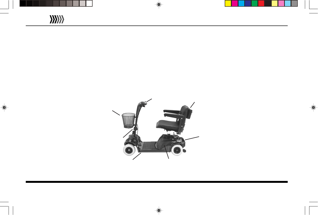
Components
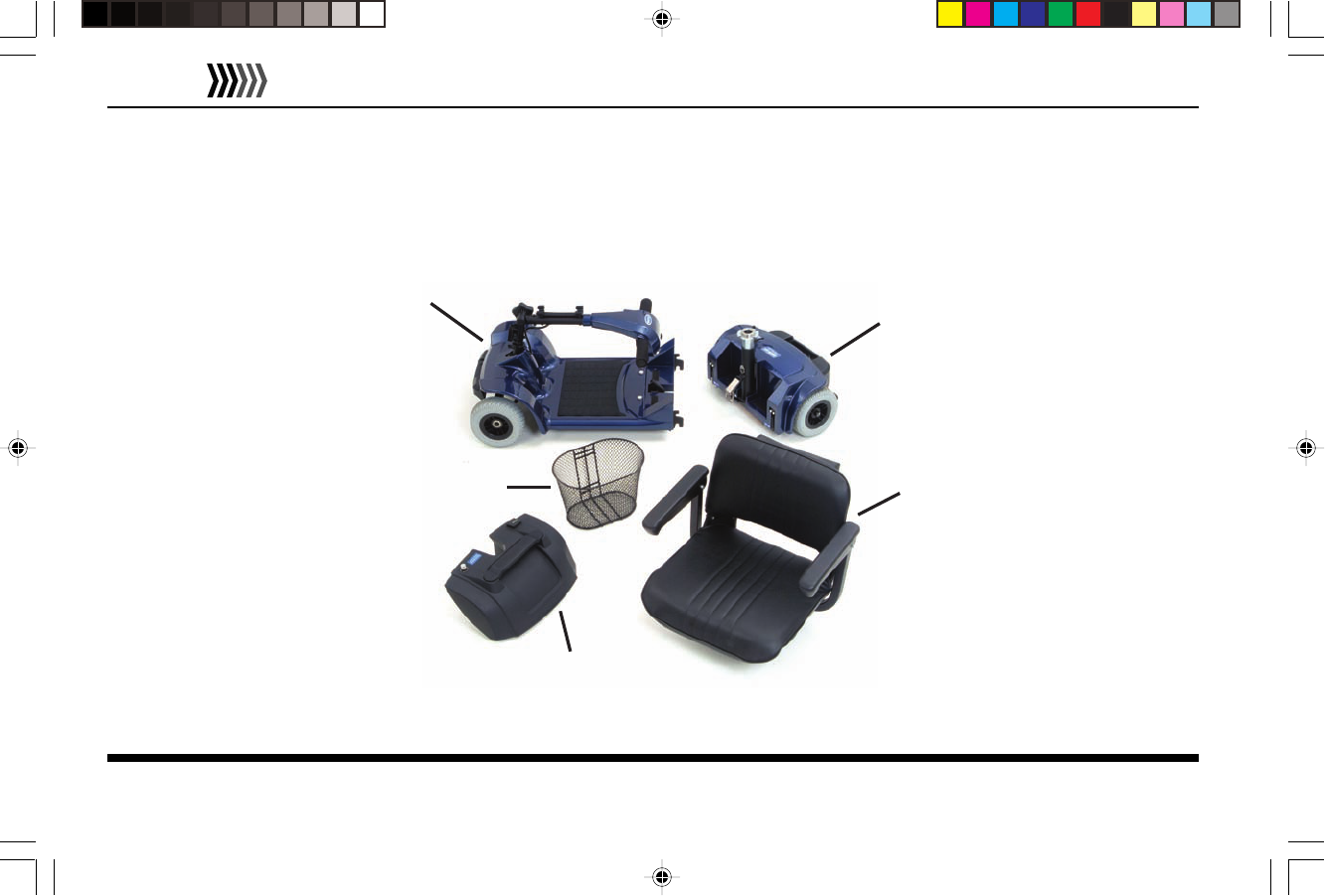
The Model 140T/140F consists of the following major components. Locations are shown in Figure 1.
Figure 1 — Model 140F Components
FRONT
BASKET
DASH AND CONTROLS
SEAT
REAR DRIVETRAIN
ASSEMBLY
REMOVABLE
BATTERY CASE
FRONT FRAME
ASSEMBLY
HANDLEBAR
ASSEMBLY
Model 140T/140F Owner’s Manual
EMC Part: 44000700 • Rev.02 • 04/19/06
7
ELECTRIC
MOBILITY
Initial Setup
Prior to using your Model 140T/140F, use the following to initially setup the vehicle for proper use and safe, comfortable
operation. Initial setup involves installing the seat and front basket. If the vehicle is delivered with the seat and basket
installed, you can skip this section and proceed with how to charge the battery before riding.
Installing Seat and Front Basket
The 140T/140F includes a swivel seat and detachable front basket that may require installation when you first receive it.
Model 140T/140F Owner’s Manual
EMC Part: 44000700 • Rev.02 • 04/19/06
8
ELECTRIC
MOBILITY
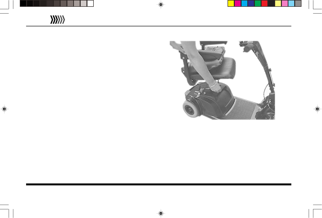
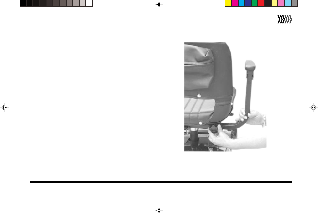
Seat Installation
To install the seat begin by pulling the locking lever back,
located beneath the seat. Insert the seat onto the seat post
tube, and release the locking lever to lock seat in position.
Turn the seat back and forth slightly allowing the lever to
lock into position. Seat installation is shown in Figure 2.
Front Basket Installation
The front Basket installs on the basket mounting brackets
located on the scooter handlebar assembly. Align basket
with mounting brackets and push firmly down to secure
basket in position.
Figure 2 - Seat Installation
Model 140T/140F Owner’s Manual
EMC Part: 44000700 • Rev.02 • 04/19/06
9
ELECTRIC
MOBILITY
Charging Battery
It is recommended to charge your batteries:
•
Upon initial receipt of your Model 140T/140F
• For 6-8 hours (overnight) after extended use during
the day
• Whenever the battery meter indicator goes into the
red area
• The battery’s life expectancy may be shortened if
batteries are left fully discharged for more than a day.
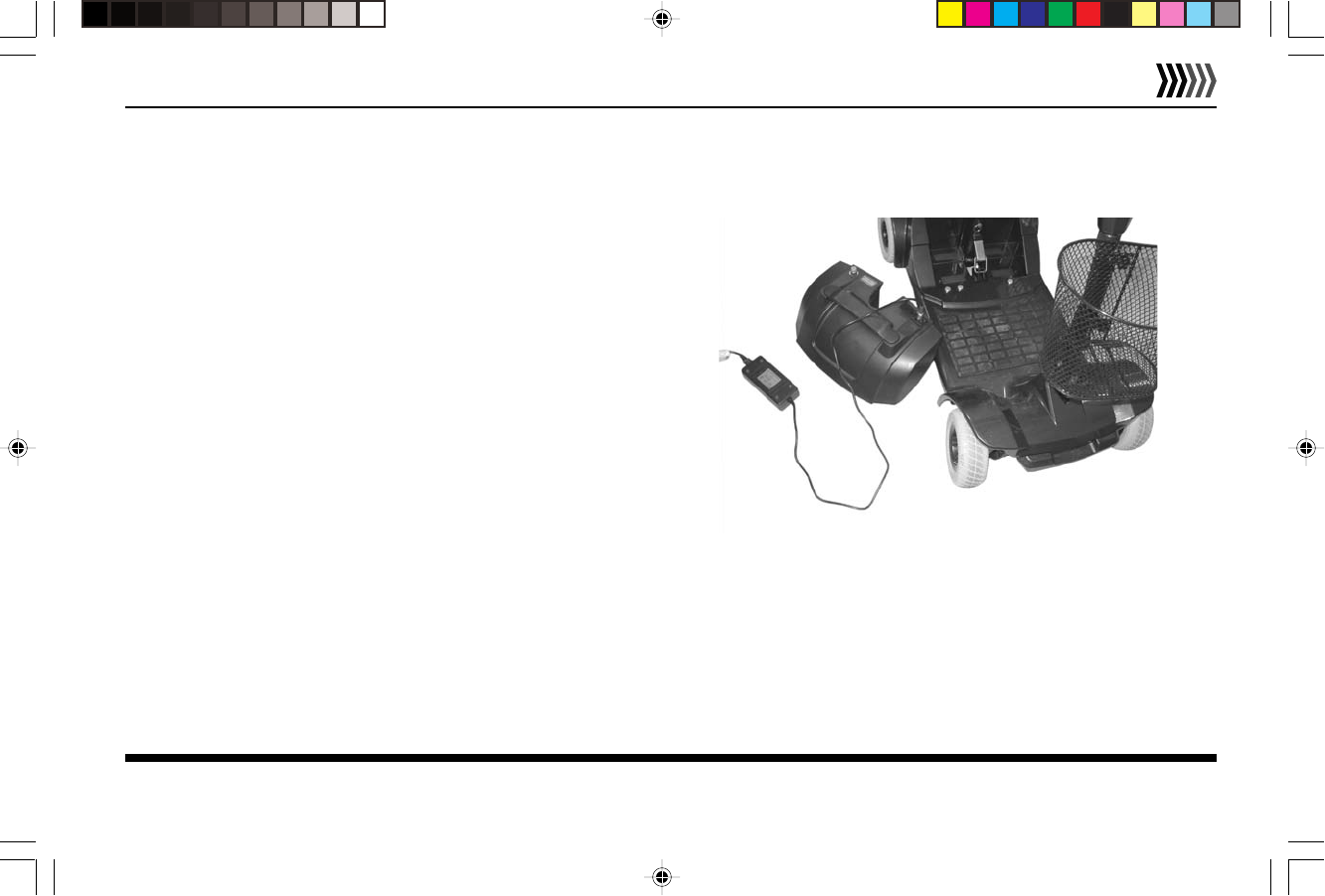
To Charge the Battery:
1.Locate and identify the separate Battery Charger and
AC line cord that accompanies the vehicle.
2.The Battery can be charged either on or off the vehicle.
If more convenient, detach Battery Case from vehicle
and set on dry, flat surface as shown in Figure 3.
Figure 3 - Battery Charging, Off Vehicle
Model 140T/140F Owner’s Manual
EMC Part: 44000700 • Rev.02 • 04/19/06
10
ELECTRIC
MOBILITY
3.Locate Charger connection on top side of Battery Case
housing. It is covered by a square, hinged door labeled
“Charger.” Battery Case charging connection is shown
in Figure 4.
4.Attach the separate AC line cord into the Charger.
Connect other end to a 3 prong electrical outlet.
There is an LED located on the Charger housing
labeled High Power Tech. The LED will turn red to
indicate charger is ready.
5.Plug the round, 3-prong plug attached to the Charger
into charger connection on Battery Case housing.
6.The Charger LED Indicator on the charger housing
should appear orange while charging. When LED
appears green, Battery is fully charged.
7.If Battery Case was removed from vehicle, replace it
and make sure it is secured in place.
Figure 4 - Battery Case Charger Connection
Model 140T/140F Owner’s Manual
EMC Part: 44000700 • Rev.02 • 04/19/06
11
ELECTRIC
MOBILITY
Operating Controls
The vehicle includes the following controls used for
operation.
Dash Controls
All major controls used while driving are located on the
dash mounted on the handlebar assembly. The dash of
Model 140T/140F is shown in Figure 5. Each control is
described in the following.
Speed Dial — The Speed Dial regulates the maximum
speed. Start at the slowest speed until you feel confident
with controlling your vehicle safely. Turning the speed dial
to the left (towards the turtle symbol) decreases maximum
speed. Turning it to the right (towards the rabbit symbol)
increases maximum speed.
Controls and Adjustments
Before driving, it is suggested that you learn about the controls of the scooter and how to perform some initial
adjustments to increase safety and improve rider comfort.
BATTERY METER
LED STATUS
INDICATOR
SPEED DIAL
HORN
REVERSE LEVER
FORWARD LEVER
Figure 5 - Dash Controls
Model 140T/140F Owner’s Manual
EMC Part: 44000700 • Rev.02 • 04/19/06
12
ELECTRIC
MOBILITY
LED Status Indicator - When the scooter is on, and all conditions are normal, the LED will be on. When there is a fault
detected that needs attention, the LED will flash. Codes and faults are listed on page 37.
Battery Meter— This instrument shows the level of charge in the batteries. When in the green area the batteries are
fully charged. When in the yellow area the batteries need recharging and when in the red area the batteries require
immediate recharging. NOTE: When the vehicle is climbing an incline the level may drop momentarily, this is normal.
Battery Power Save Feature - The 140T/140F is equipped
with a power save feature and will shut down automatically
in order to conserve battery power when not operated for
10 minutes or more. The vehicle can be turned on again by
cycling the On/Off keyswitch from “On” to “Off” and then
“On” again.
Horn - Pressing the horn button on the dash sounds the
horn. Releasing the horn button deactivates the horn.
The horn is useful to warn people or animals that you are
coming towards them. You may also find it helpful to use it
when rounding blind corners or going in reverse.
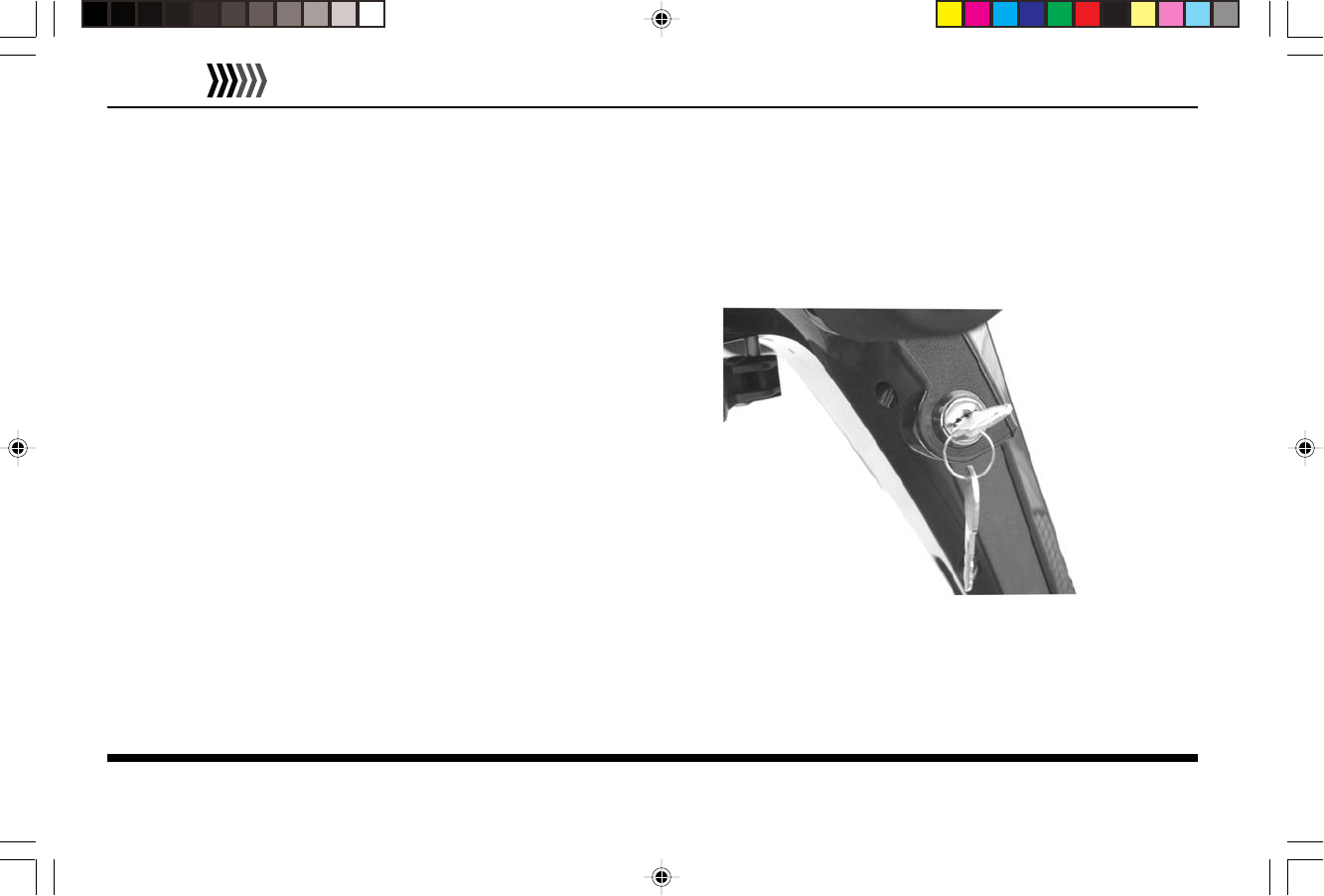
On/Off Key - Controls power. Turning the key clockwise
turns power “On.” When “On” the Battery Gauge will
indicate battery level. Turning the key counterclockwise
turns the vehicle “Off.” Key location shown in Figure 6,
with key in the “On” position.
Figure 6 — Key Location
Model 140T/140F Owner’s Manual
EMC Part: 44000700 • Rev.02 • 04/19/06
13
ELECTRIC
MOBILITY
Forward/Reverse Engager Levers — Selects movement
direction and speed of the vehicle. To move forward, push
the right lever towards the handle grip. To move in reverse,
push the left lever towards the handle grip. Operating
speed is proportional to the amount you push each lever.
Smoother starts and stops can be accomplished by
gradually moving each lever.
Adjusting Armrests
Your vehicle includes armrests. You can adjust the width
between armrest so that you are seated in the most
comfortable position possible. Armrest adjustments are
shown in Figure 7.
To Adjust Armrest Width:
1. Loosen Adjustment Knobs on armrest bracket
2. Slide armrest support to desired position
3. Tighten Adjustment Knob to secure armrest bracket
4. Repeat with other side armrest
Figure 7 - Armrest Adjustment
Model 140T/140F Owner’s Manual
EMC Part: 44000700 • Rev.02 • 04/19/06
14
ELECTRIC
MOBILITY
WARNING!
DO NOT use armrest as support when transferring on or off the vehicle. Armrests
are not designed to support weight of rider when getting on or off the seat.
Adjusting Seat
Seat Post Height Adjustments:
The seat height can be adjusted manually. The seat post
tube has two holes, so you can adjust the seat height that is
most comfortable. The seat post tube and seat height
locking pin is shown in Figure 8.
To Adjust Seat Post Height:
1. Remove the seat by holding the locking lever backward
and lift the seat straight up and off the Seat Post Tube.
2. Hold the Seat Post Tube with one hand and pull out the
Seat Height Locking Pin with the other.
Figure 8 - Seatpost Height Adjustment
SEAT POST TUBE
SEAT POST BASE
SEAT HEIGHT
LOCKING PIN
Model 140T/140F Owner’s Manual
EMC Part: 44000700 • Rev.02 • 04/19/06
15
ELECTRIC
MOBILITY
3. Position the Adjustable Seat Post Tube to your desired height and align the holes in the Seat Post Base and Seat Post
Tube. Insert the Seat Height Locking Pin, making sure the pin is secure.
4. Replace the seat by holding the locking lever backwards, insert the seat onto the Seat Post Tube, and release the locking
lever to lock the seat in place. Turn seat back and forth slightly allowing the lever to lock into position.
Seat Swivel Positions:
The seat swivel lever (located underneath seat base on right) allows the seat rotation in 45 degree increments.
You may use this feature to make it easier to transfer in and out of the seat.
1. Pull the locking lever backwards to unlock and rotate the seat.
2. Pivot the seat to the position you desire.
3. Release the lever and try to turn the seat back and forth slightly allowing the lever to lock into position.
Model 140T/140F Owner’s Manual
EMC Part: 44000700 • Rev.02 • 04/19/06
16
ELECTRIC
MOBILITY
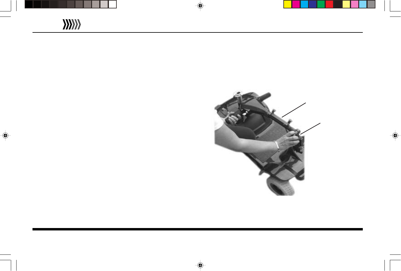
Adjusting Handlebar Assembly
The angle of the handlebar assembly and dash may be adjusted to the individual rider’s preference. Multiple angles are
available to reposition the handlebar assembly. The handlebar assembly angle adjustment knob allows you to position the
handlebar assembly closer or further away for better access to the controls.
Figure 9 -Handlebar Assembly Adjustment
HANDLEBAR
ASSEMBLY
HANDLEBAR
ADJUSTMENT
KNOB
To Adjust Handlebar Assembly Position:
1. Locate the black angle adjusting knob located on the right
side of the handlebar assembly.
2. Hold the handlebar with one hand and loosen the hand
knob.
3. Adjust the angle of the handlebar assembly to a
comfortable position.
4. Turn the knob clockwise to tighten. As you tighten the knob
gently rock the handlebar assembly back and forth to allow
the teeth on the clamp to engage tightly.
5. Check the knob daily to ensure it’s tight.
Handlebar Assembly Adjustment is shown in Figure 9.
Model 140T/140F Owner’s Manual
EMC Part: 44000700 • Rev.02 • 04/19/06
17
ELECTRIC
MOBILITY
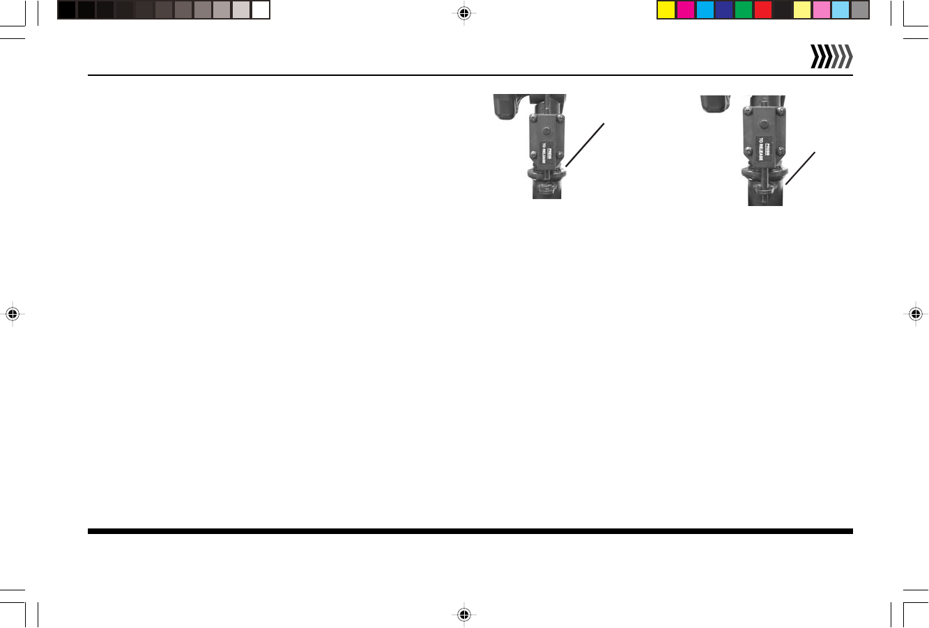
Handlebar Assembly Lock
If your 140T/140F is equipped with a handlebar assembly
lock make sure to release the lock by pushing the lock
release button. To engage lock push the locking pin down
until you hear the pin click into place. Handlebar Assembly
Lock is shown in Figure 10.
Accessories
Your 140T/140F can include several useful accessories to make your riding experience more enjoyable, convenient, and
easier. These accessories can include:
•Lifting Harness
•Storage Bags
•Beverage Holder
•Extra Battery Pack
•SaddleBag
•Weather Cover
•Rear View Mirror
These accessories are available separately and come with complete instructions for installation and use with your Model
140T/140F vehicle. Contact your Customer Service representative for further information.
Figure 10 - Handlebar Assembly Lock
LOCKED
POSITION
LOCK RELEASED
POSITION
Model 140T/140F Owner’s Manual
EMC Part: 44000700 • Rev.02 • 04/19/06
18
ELECTRIC
MOBILITY
Using the 140T/140F
Once you’ve gotten familiar with the 140T/140F components, controls, and have charged the Battery, you can use the
following section to use it. This section presents instructions for:
•Day-to-Day Use
•Shipping and Transport
If you are unsure of how to operate your vehicle, go back to the previous section before attempting any use.
Day-to-Day Use
The following describes using your 140T/140F during general, daily operation, including:
•Transferring On & Off
•Driving
•Freewheel Operation
Model 140T/140F Owner’s Manual
EMC Part: 44000700 • Rev.02 • 04/19/06
19
ELECTRIC
MOBILITY
Transferring On or Off the Vehicle
Your 140T/140F has been designed to make transferring on and off the vehicle as easy as possible.
WARNING!
Make sure key is either in the OFF position or removed before transferring
ON or OFF the vehicle.
Use the following recommendations to assist you in making a more comfortable transfer.
•Use the handlebar assembly angle adjustment knob to move the handlebar assembly away from seat for ease of
transfer.
•Lift the folding armrests of the seat up and out of your way. Be sure to move them down into the riding
position before operating.
•Use the footrest area of the frame for assistance when transferring on and off.
Model 140T/140F Owner’s Manual
EMC Part: 44000700 • Rev.02 • 04/19/06
20
ELECTRIC
MOBILITY
Driving
Once seated on your vehicle, driving is as simple as using the Engager Levers to move forward (right lever) or reverse (left
lever) and steering in the desired direction. Before driving, however, you should keep in mind the following
recommendations.
•Handlebar assembly is adjusted to comfortable riding position.
•Motor is engaged. Check Brake Lever. Should be in “DRIVE” position. See Figure 11, page 22.
•Armrests are locked into driving position.
•Handlebar Assembly Lock is in the unlocked position.
WARNING!
If any of these items are questionable, DO NOT OPERATE! Check before driving.
Failure to disregard these conditions may cause accidents or injuries.
Speed Settings
The overall forward/reverse speed range of the vehicle is selected from the Speed dial on the dash. Lower settings
(indicated by the turtle symbol) result in slower speeds. Higher settings (indicated by the rabbit symbol) provide faster
speeds. When first operating your vehicle, select slower settings until you feel comfortable.
Model 140T/140F Owner’s Manual
EMC Part: 44000700 • Rev.02 • 04/19/06
21
ELECTRIC
MOBILITY
Inclines
It is recommended that speed be reduced when traveling on (up or down) inclines. Select the slowest speed
setting that will still allow the vehicle to climb the incline.
NEVER try to turn around on an incline!
If vehicle stops on an incline, DO NOT attempt to continue.
When stopped on an incline, back down with the speed set at “slow” and back down in one continuous
movement. DO NOT start and stop.
Always lean forward when traveling on inclines (up or down) for greater stability.
Cornering & Turning
ALWAYS reduce to a safe speed when making a turn or going around a corner.
Curbs and Small Obstacles
DO NOT attempt to ride over curbs or any other obstructions higher than 2 inches (5 cm).
Model 140T/140F Owner’s Manual
EMC Part: 44000700 • Rev.02 • 04/19/06
22
ELECTRIC
MOBILITY
Brake Release Lever
The 140T/140F features a “push mode” to allow it to be pushed by hand . To activate manually, turn the key switch OFF
and locate the brake release lever on the right side of the rear cover. The Brake Release Lever is shown in Figure 11.
Push lever towards front of vehicle, “PUSH MODE” position, to disengage the brake. Move lever back towards rear of
vehicle, “DRIVE” position, to reengage the brake. When your vehicle is in “push mode”, brakes will not operate.
WARNING!
Never sit in vehicle if it is in “PUSH MODE” on an incline.
Figure 11 - Brake Release Lever and Overload Fuse
OVERLOAD FUSE
BRAKE RELEASE
LEVER
Model 140T/140F Owner’s Manual
EMC Part: 44000700 • Rev.02 • 04/19/06
23
ELECTRIC
MOBILITY
Overload Fuse
If the vehicle is overloaded or is used outside its design parameters it may cause the overload fuse to engage. If this
happens the vehicle will stop and beep to alert you. The Overload Fuse in shown in Figure 11.
To Reset the Overload Fuse:
1. Turn key switch to “Off” position.
2. Wait 1-2 minutes.
3. Push overload fuse in.
4. Turn key switch to “On” position.
Model 140T/140F Owner’s Manual
EMC Part: 44000700 • Rev.02 • 04/19/06
24
ELECTRIC
MOBILITY
Disassembly & Re-assembly
The 140T/140F can be quickly and easily disassembled into four components for storage or transport, then re-assembled
when needed. Instructions to take your Model 140T/140F apart and put it back together are presented in this section.
Figure 12 — Model 140F Disassembled
FRONT FRAME AND
HANDLEBAR ASSEMBLY
BATTERY CASE
FRONT BASKET
REAR DRIVETRAIN
ASSEMBLY
SEAT
Model 140T/140F Owner’s Manual
EMC Part: 44000700 • Rev.02 • 04/19/06
25
ELECTRIC
MOBILITY
Disassembling Your Model 140T/140F
Taking Model 140T/140F apart involves removing the seat
and Battery Case, lowering the handlebar assembly, and
disconnection the front frame assembly from the rear
drivetrain assembly.
To Disassemble Model 140T/140F:
1.Turn power “OFF.” Fold seat back down.
2.Remove the seat by holding locking lever backward and
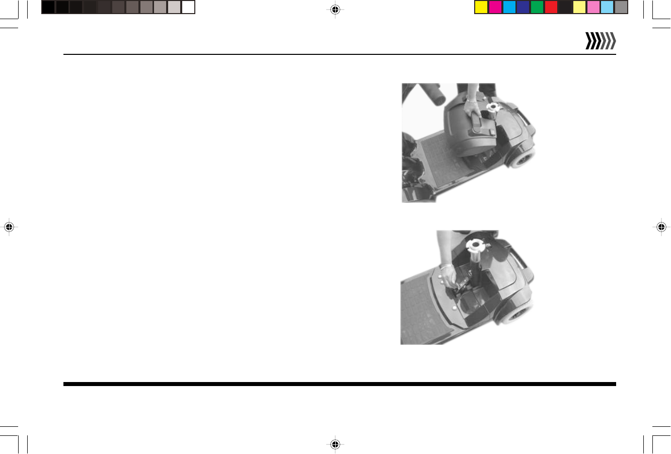
lift the seat up and off the seat post tube.
3.Lift Battery Case by handle and pull up to remove, as
shown in Figure 13. The Battery Case is attached with
Velcro and may need some effort to lift.
4.Pull release latch forward and unfasten the frame
buckle, as shown in Figure 14.
Figure 13 - Battery Case Removal
Figure 14 - Frame Buckle Unfastened
Model 140T/140F Owner’s Manual
EMC Part: 44000700 • Rev.02 • 04/19/06
26
ELECTRIC
MOBILITY
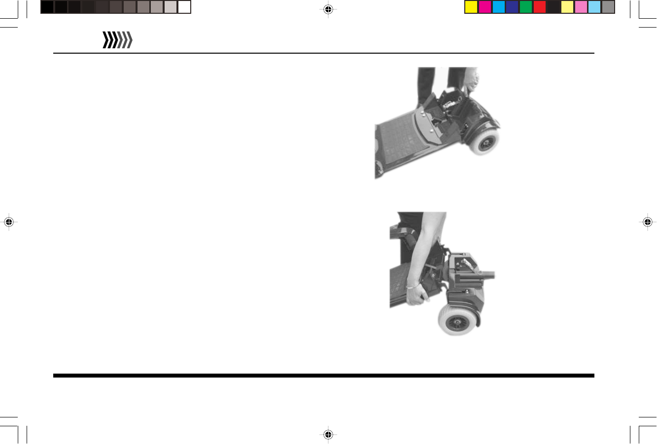
5.Lower handlebar assembly onto the frame using the
handlebar assembly adjustment knob.
6.Grip seat post with one hand and angle the rear
section upwards, as shown in Figure 15.
7. To detach the front frame from the rear, lift front frame
Gebruikershandleiding.com neemt misbruik van zijn services uitermate serieus. U kunt hieronder aangeven waarom deze vraag ongepast is. Wij controleren de vraag en zonodig wordt deze verwijderd.
Product:
Spelregels forum
Om tot zinvolle vragen te komen hanteren wij de volgende spelregels:
lees eerst de handleiding door;
controleer of uw vraag al eerder door iemand anders is gesteld;
probeer uw vraag zo duidelijk mogelijk te stellen;
heeft u een probleem en al geprobeerd om dit op te lossen, vermeld dit erbij aub;
heeft u een oplossing gekregen van een bezoeker dan horen wij dat graag in dit forum;
wilt u een reactie geven op een vraag of antwoord, gebruik dan niet dit formulier maar klik op de knop 'reageer op deze vraag';
uw vraag wordt direct op de website gezet; vermijd daarom persoonlijke gegevens in te vullen;
Belangrijk! Als er een antwoord wordt gegeven op uw vraag, dan is het voor de gever van het antwoord nuttig om te weten als u er wel (of niet) mee geholpen bent! Wij vragen u dus ook te reageren op een antwoord.
Belangrijk! Antwoorden worden ook per e-mail naar abonnees gestuurd. Laat uw emailadres achter op deze site, zodat u op de hoogte blijft. U krijgt dan ook andere vragen en antwoorden te zien.
Abonneren
Abonneer u voor het ontvangen van emails voor uw Rascal EM 140T bij:
nieuwe vragen en antwoorden
nieuwe handleidingen
U ontvangt een email met instructies om u voor één of beide opties in te schrijven.
Ontvang uw handleiding per email
Vul uw emailadres in en ontvang de handleiding van Rascal EM 140T in de taal/talen: Engels als bijlage per email.
De handleiding is 0,72 mb groot.
U ontvangt de handleiding per email binnen enkele minuten. Als u geen email heeft ontvangen, dan heeft u waarschijnlijk een verkeerd emailadres ingevuld of is uw mailbox te vol. Daarnaast kan het zijn dat uw internetprovider een maximum heeft aan de grootte per email. Omdat hier een handleiding wordt meegestuurd, kan het voorkomen dat de email groter is dan toegestaan bij uw provider.
Stel vragen via chat aan uw handleiding
Stel uw vraag over deze PDF
Uw handleiding is per email verstuurd. Controleer uw email
Als u niet binnen een kwartier uw email met handleiding ontvangen heeft, kan het zijn dat u een verkeerd emailadres heeft ingevuld of dat uw emailprovider een maximum grootte per email heeft ingesteld die kleiner is dan de grootte van de handleiding.
Er is een email naar u verstuurd om uw inschrijving definitief te maken.
Controleer uw email en volg de aanwijzingen op om uw inschrijving definitief te maken
U heeft geen emailadres opgegeven
Als u de handleiding per email wilt ontvangen, vul dan een geldig emailadres in.
Uw vraag is op deze pagina toegevoegd
Wilt u een email ontvangen bij een antwoord en/of nieuwe vragen? Vul dan hier uw emailadres in.