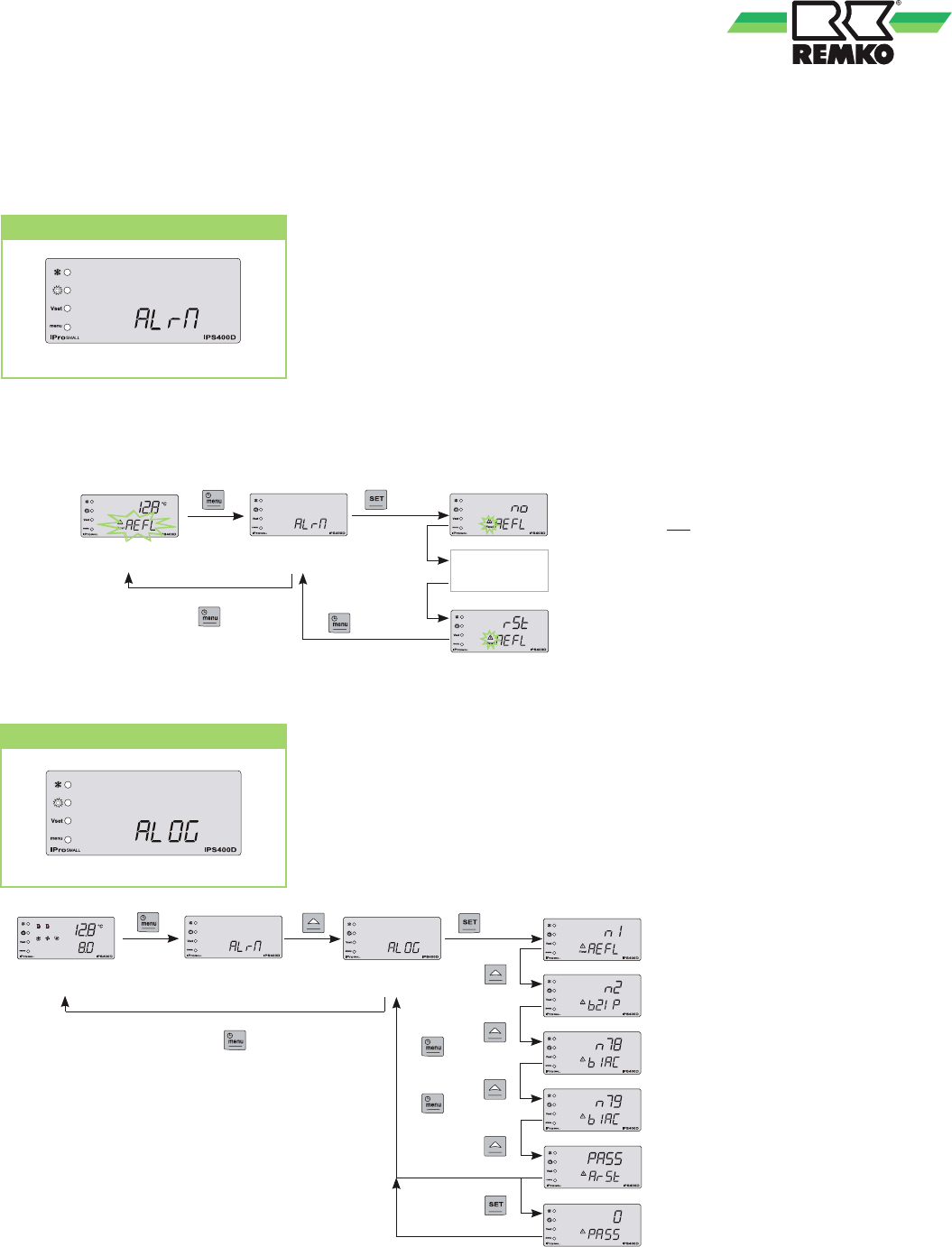
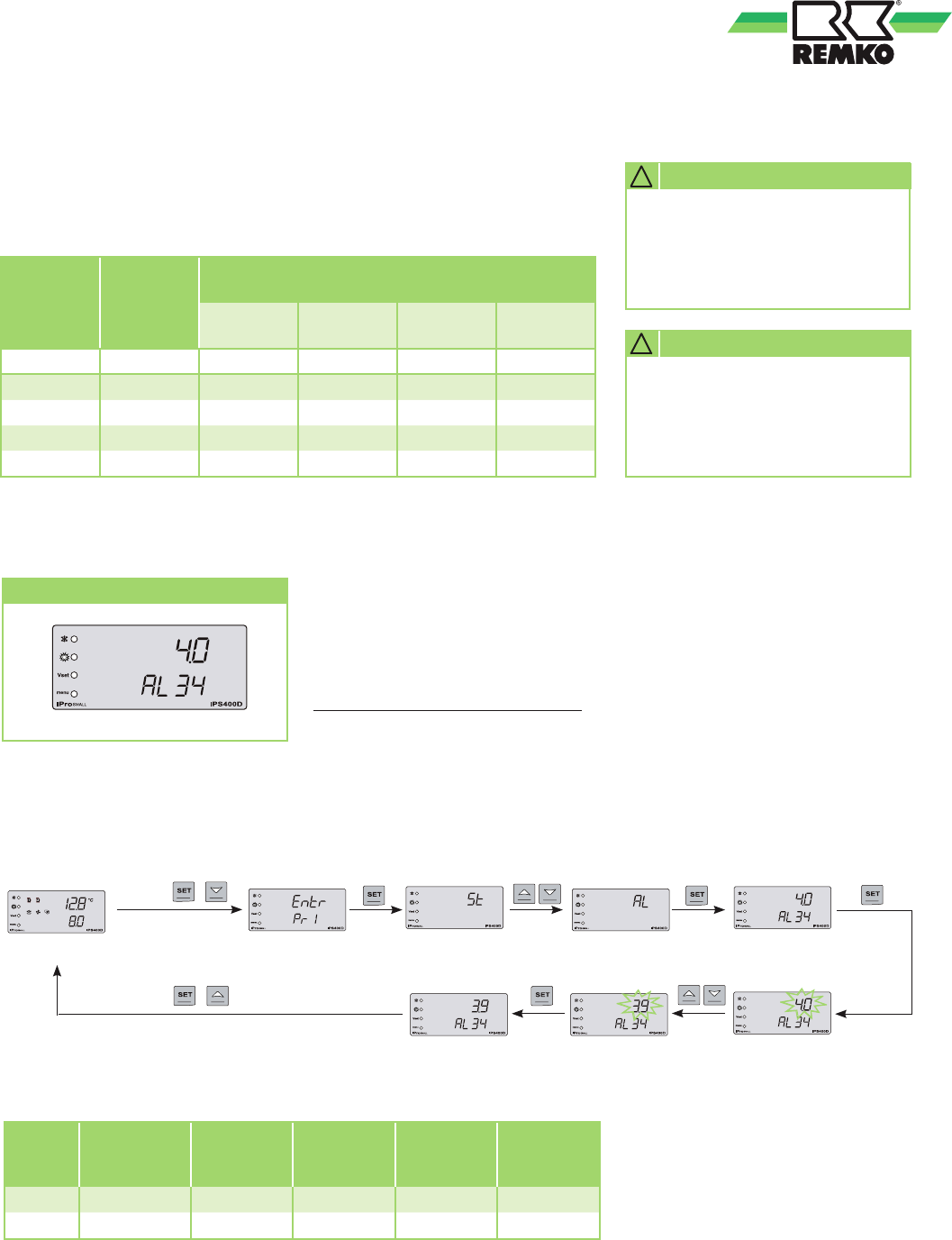
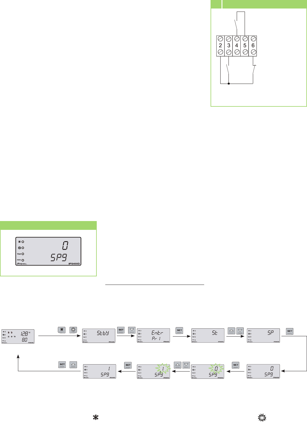
1. Faults with automatic reset: The faults are reset automatically.
2. Faults with manual reset: The fault can be reset only by a specialist after the fault has been remedied.
3. Faults with partial manual reset: The fault is reset automatically at first; after that, it can only be reset manually by a specialist after the fault has been remedied.
REMKO KWG
20
Mounting instructions for expert personnel
■
For the installation of the entire
system, the operating instruc-
tions of the indoor units and
the chiller and/or heating sys-
tem must be observed.
■
The indoor units and chiller
work independently. They do
not have to be interconnected.
■
Select an installation site that
guarantees free air inlet and
outlet. See the "Minimum
clearance" section.
■
Do not install the unit in the
direct vicinity of units with
intensive heat radiation.
Installation in the vicinity of
heat radiation reduces the unit
output.
■
Lift the unit only at the in-
tended points. Never load the
medium or refrigerant lines.
■
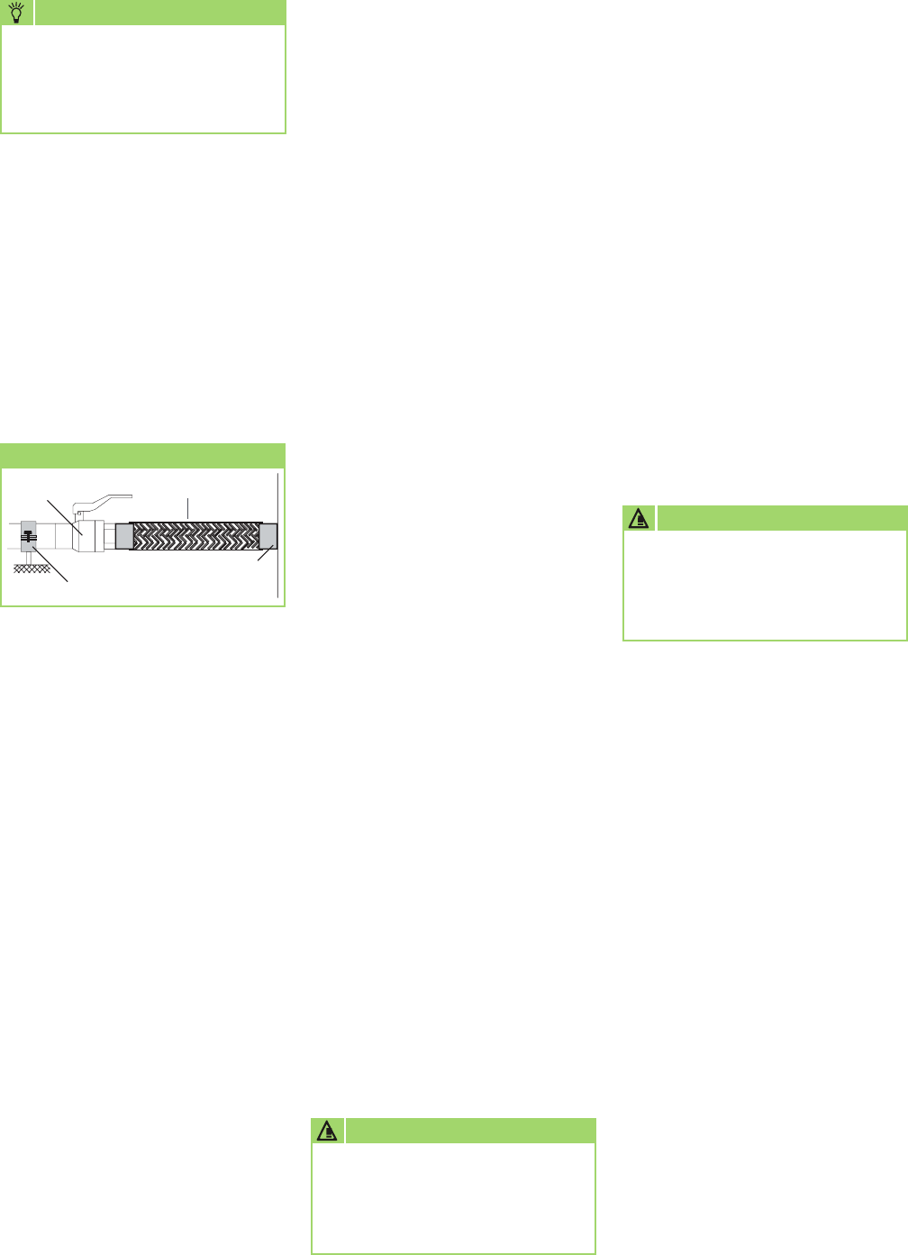
The medium connection lines,
valves, and connections must
be insulated in a vapour-
diffusion-tight manner. If
necessary, the condensate
line (only units with heat
pump function) must also be
insulated. In combined systems
with cooling and heating
modes, the requirements of
the current energy savings
ordinance (Energie-Einspar-
Verordnung (EnEV) in
Germany) must be observed.
■
Protect open lines against the
penetration of dirt. Never press
in the lines.
■
Avoid unnecessary bends.
■
Establish all electrical
connections according to the
locally valid regulations.
■
Always connect electrical
lines properly to the electrical
terminals.
Fires may otherwise result.
■
Observe the static and other
construction regulations and
conditions in regard to the
installation site.
■
When selecting the installation
site, pay attention to a possible
noise reflection of the units in
the environment and on the
mounting surface.
■
To prevent the transmission of
vibrations to the mounting sur-
face, the units must be mount-
ed on vibration-absorbent
materials or vibration-isolated
foundations.
Make sure the lines are also
vibration-isolated.
■
If special requirements are
placed on the noise emissions
of the installation site, locally
adapted sound insulation
measures must be taken.
In such cases, please contact
a corresponding specialist
consultant.
Important information
prior to installation
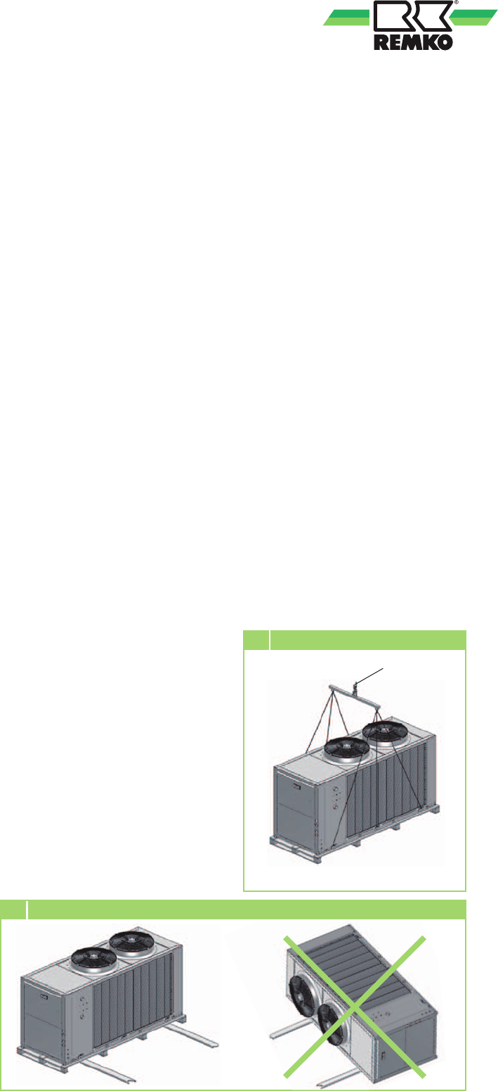
2 Vertical unit transport
Tension point
1 Upright unit transport
Transport
■
Bring the unit as close
as possible to the installation
site
while still in the original
packaging. In this way, you can
prevent
transport damage.
■
The units may be moved only
into their mounting position
(upright) using suitable means
of transport (Figure 1).
Secure against tipping!
■
The unit must be transported
in a vertical position to higher
installation sites (Figure 2).
■
Check the package contents
for completeness and check the
unit for visible transport dam-
age.
Report any damage immediate-
ly to your contracting partners
and the shipping company.
21
Lift
Min.
2000 mm
Tension point
Cross beam wider than the unit width
2400 mm
Tension point
Cross beam wider
than the unit width
Wall breakthroughs
■
We recommend that you insu-
late the inside of the hole or use
a PVC pipe to prevent damage
to the lines.
■
After mounting, close off the
wall breakthrough on site with
suitable sealing compound. Do
not use materials containing
cement or lime!
Mounting materials
The unit is attached to the floor
using vibration dampers (acces-
sory). When fastening the unit to
the wall, particularly observe the
load capacity of the bracket and
the wall.
Selection of the installation
site
The unit is designed for outdoor,
horizontal, upright installation. The
installation site of the unit must
be horizontal, even, and firm. In
addition, the unit must be secured
against tipping.
The unit can be installed both
outside and inside a building.
During outdoor installation, ob-
serve the following notices regard-
ing the protection of the unit
against the effects of weathering.
Definition of the
danger zone
Only authorised and trained
personnel may have access to the
unit. If unauthorised personnel
could enter the danger zones, they
must be labelled with correspond-
ing signs / barriers, etc.
■
The outer danger zone sur-
rounds the unit with at least
2 m, measured from the unit
housing.
■
The outer danger zone can dif-
fer as a result of the setup. The
specialist company performing
the installation is responsible for
this matter.
■
The inner danger zone is
located inside the machine
and can be accessed only
using corresponding tools.
Unauthorised persons must not
access this danger zone!
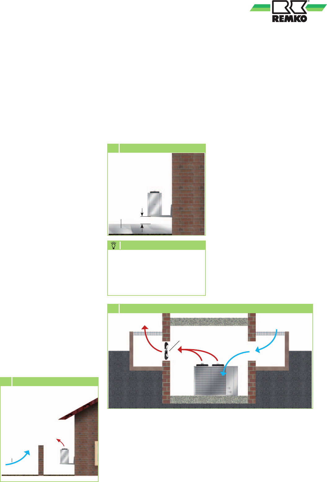
Rain
In case of installation onto the
floor or roof, there must be a mini-
mum floor clearance of 10 cm.
In the case of units for cooling and
heating (heat pump function only),
a raised installation increases the
generated heating capacity.
REMKO KWG
22
Wind
3 Wind protection
20 cm
Snow
4 Minimum distance to snow
Sun
The air-cooled condenser is a heat-
dissipating component in cooling
mode.
Direct sunlight also increases the
temperature of the fins and thus
reduces the heat dissipation of the
fin heat exchanger.
The unit should be set up on the
north side of the respective build-
ing, if possible.
On-site shading should be set up
as required.
A small roof suffices.
The emerging hot air flow, how-
ever, must not be influenced by
the measures.
Wind
If the unit is primarily installed
in windy regions, make sure that
the emerging hot air flow is dis-
sipated in the main wind direction.
If this is not possible, install wind
protection on site (Fig 3).
Make sure that the wind protec-
tion does not interfere with the air
supply of the unit.
Snow
In areas with high snowfall, the
unit should be mounted onto a
wall.
It should be mounted at least 20
cm above the expected snow-
fall height to prevent snow from
penetrating into the outdoor unit
(Fig. 4).
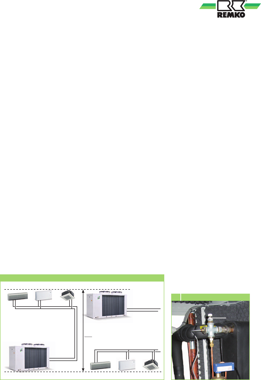
Setup inside the building
■
Provide a means of sufficient
heat dissipation if the outdoor
unit is to be installed in a cellar,
attic, utility rooms, or halls (Fig.
5).
■
Install an additional fan that
has the same air volume flow
rate of the outdoor unit to be
set up in the room and that can
compensate additional pressure
losses through air ducts
(Fig. 5).
■
Observe the static and other
construction
regulations and conditions in
regard to the building and pro-
vide sound insulation if neces-
sary.
■
Guarantee a continuous, un-
hindered air supply from the
outside, possibly using oppos-
ing, sufficiently large air open-
ings (Fig. 5).
Due to ambient influences,
such as rain, sun, wind, and
snow, the generated cooling or
heating capacity will change.
NOTE
Hot air
Cold
fresh air
Light
shaft
Chiller
Hot air
Light
shaft
Additional
fan
5 Installation inside the building (cooling mode)
23
Installation
NOTE
Installation must only be car-
ried out by authorised special-
ists.
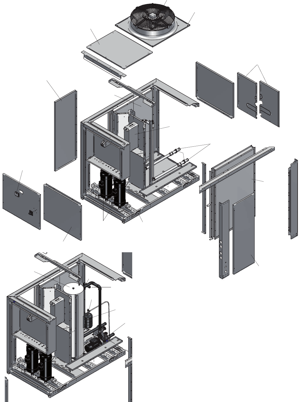
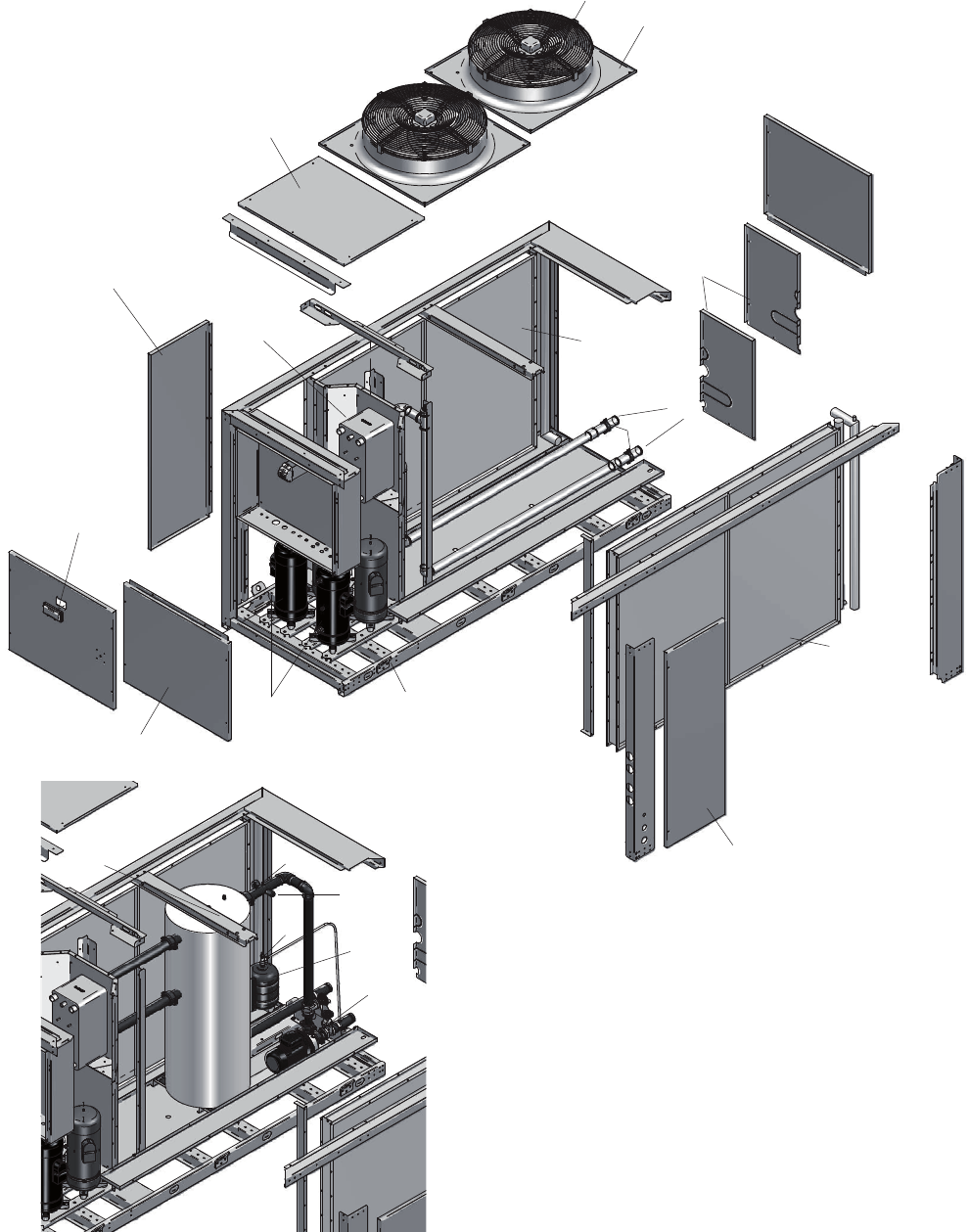
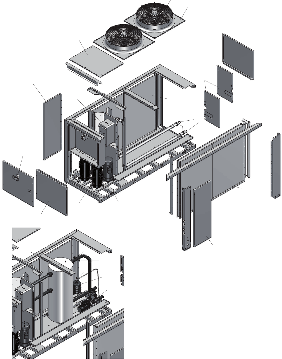
Unit installation
1. Mount the vibration dampers
(accessory) under the unit.
2. Install the unit to statically per-
missible parts of the building.
3. Make sure that no structure-
borne noise is transmitted to
parts of the building.
4. Connect the medium lines.
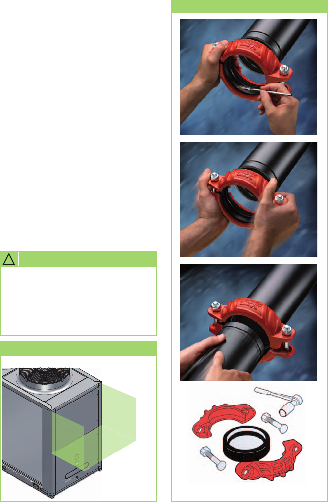
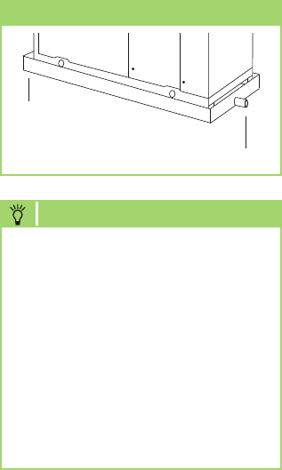
Disassembly of the transport pal-
lets
The units must be equipped with
transport pallets for transport
purposes. They must be removed
before mounting.
Transport packaging
Transport pallet
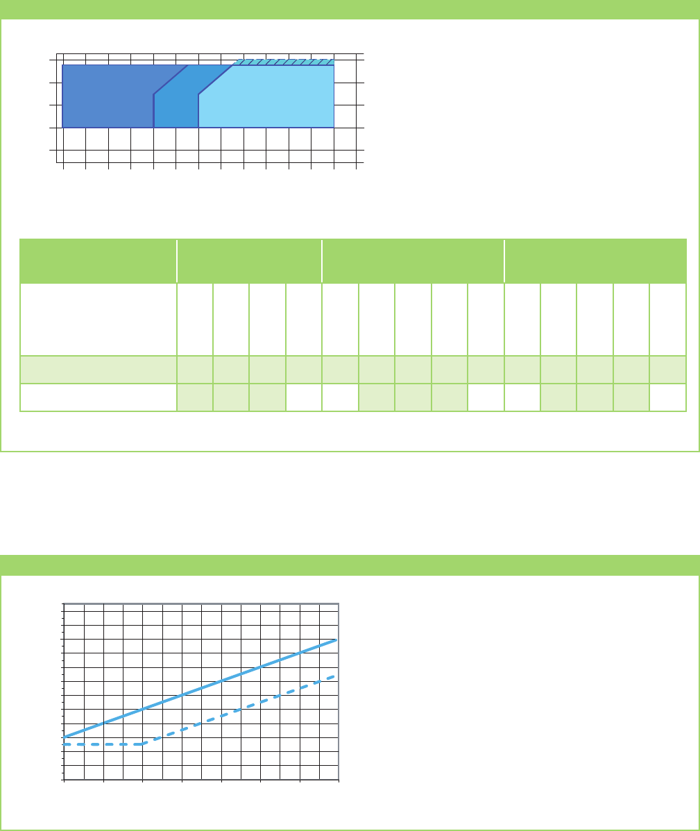
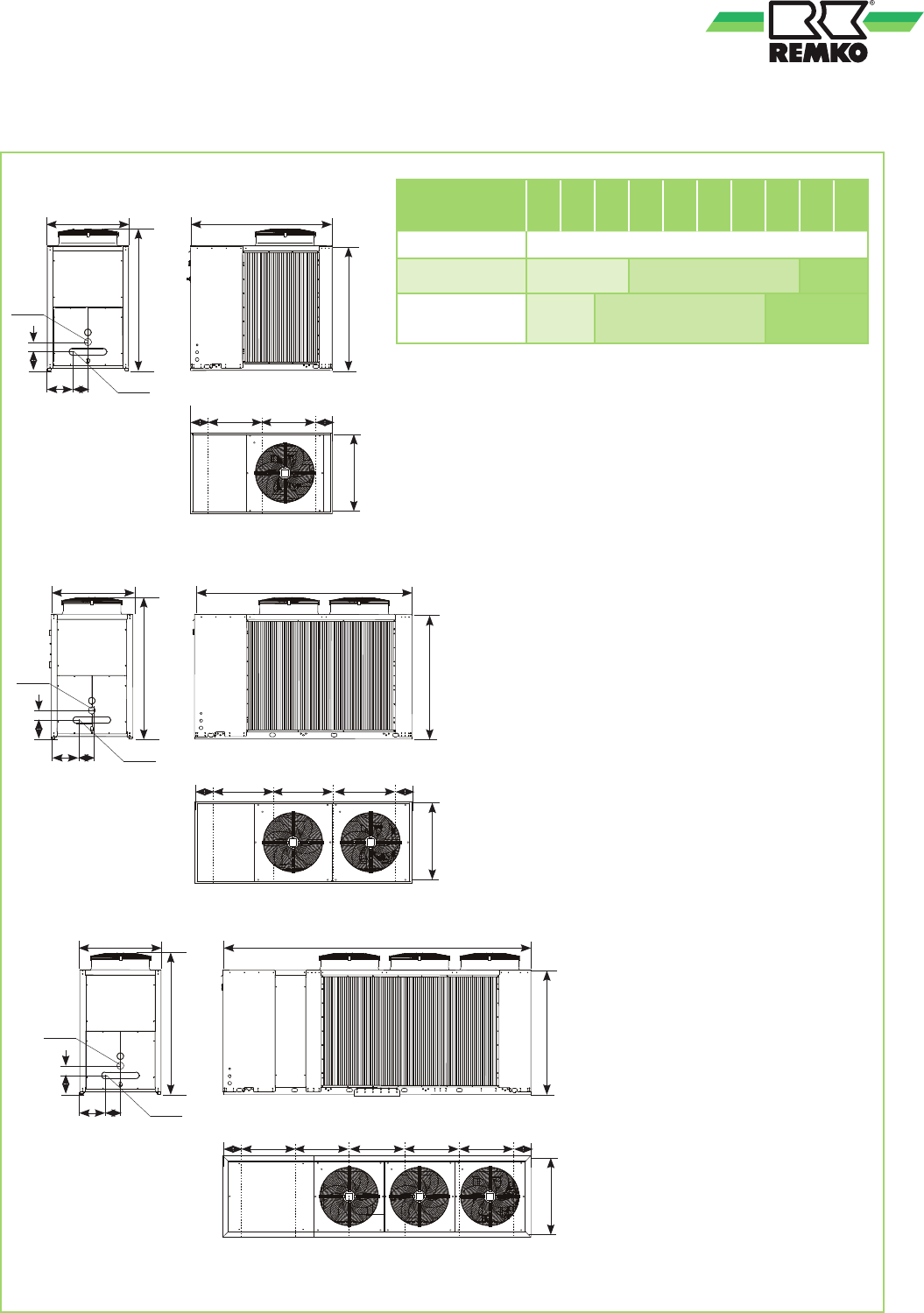
Minimum clearances
The following figure shows the minimum clearances for a malfunction-free operation of the units.
These protection zones are used for unhindered air inlet and outlet, for ensuring sufficient space for mainte-
nance and repairs, and for protecting the unit against damage.
Gebruikershandleiding.com neemt misbruik van zijn services uitermate serieus. U kunt hieronder aangeven waarom deze vraag ongepast is. Wij controleren de vraag en zonodig wordt deze verwijderd.
Product:
Spelregels forum
Om tot zinvolle vragen te komen hanteren wij de volgende spelregels:
lees eerst de handleiding door;
controleer of uw vraag al eerder door iemand anders is gesteld;
probeer uw vraag zo duidelijk mogelijk te stellen;
heeft u een probleem en al geprobeerd om dit op te lossen, vermeld dit erbij aub;
heeft u een oplossing gekregen van een bezoeker dan horen wij dat graag in dit forum;
wilt u een reactie geven op een vraag of antwoord, gebruik dan niet dit formulier maar klik op de knop 'reageer op deze vraag';
uw vraag wordt direct op de website gezet; vermijd daarom persoonlijke gegevens in te vullen;
Belangrijk! Als er een antwoord wordt gegeven op uw vraag, dan is het voor de gever van het antwoord nuttig om te weten als u er wel (of niet) mee geholpen bent! Wij vragen u dus ook te reageren op een antwoord.
Belangrijk! Antwoorden worden ook per e-mail naar abonnees gestuurd. Laat uw emailadres achter op deze site, zodat u op de hoogte blijft. U krijgt dan ook andere vragen en antwoorden te zien.
Abonneren
Abonneer u voor het ontvangen van emails voor uw REMKO KWG950 bij:
nieuwe vragen en antwoorden
nieuwe handleidingen
U ontvangt een email met instructies om u voor één of beide opties in te schrijven.
Ontvang uw handleiding per email
Vul uw emailadres in en ontvang de handleiding van REMKO KWG950 in de taal/talen: Engels als bijlage per email.
De handleiding is 7,1 mb groot.
U ontvangt de handleiding per email binnen enkele minuten. Als u geen email heeft ontvangen, dan heeft u waarschijnlijk een verkeerd emailadres ingevuld of is uw mailbox te vol. Daarnaast kan het zijn dat uw internetprovider een maximum heeft aan de grootte per email. Omdat hier een handleiding wordt meegestuurd, kan het voorkomen dat de email groter is dan toegestaan bij uw provider.
Uw handleiding is per email verstuurd. Controleer uw email
Als u niet binnen een kwartier uw email met handleiding ontvangen heeft, kan het zijn dat u een verkeerd emailadres heeft ingevuld of dat uw emailprovider een maximum grootte per email heeft ingesteld die kleiner is dan de grootte van de handleiding.
Er is een email naar u verstuurd om uw inschrijving definitief te maken.
Controleer uw email en volg de aanwijzingen op om uw inschrijving definitief te maken
U heeft geen emailadres opgegeven
Als u de handleiding per email wilt ontvangen, vul dan een geldig emailadres in.
Uw vraag is op deze pagina toegevoegd
Wilt u een email ontvangen bij een antwoord en/of nieuwe vragen? Vul dan hier uw emailadres in.