815521
1
Verklein
Vergroot
Pagina terug
1/40
Pagina verder
101/247080-803J
Owners Manual
Operation & Care
INSTALLER: Leave this manual with party responsible for use and operation.
OWNER: Retain this manual for future reference.
Contact your dealer with questions regarding installation, operation or service.
Installation and service of this appliance should be performed by
qualified personnel. Hearth & Home Technologies recommends
HHT Factory Trained or NFI certified professionals.
If the information in these instructions is
not followed exactly, a re could result
causing property damage, personal
injury, or death.
• Donotstoreorusegasolineorotherammablevapors
andliquidsinthevicinityofthisoranyotherappliance.
• Donotoverre-Ifapplianceorchimneyconnector
glows, you are over ring. Over ring will void
yourwarranty.
• Complywithallminimumclearancestocombustibles
asspecied.Failuretocomplymaycausehousere.
NOTE: To obtain a French translation of this manual,
pleasecontactyourdealerorvisitwww.quadrare.com
REMARQUE :Pourobtenirunetraductionfrançaisede
ce manuel, s’il vous plaît contacter votre revendeur ou
visitezwww.quadrare.com
R
TREKKER FREE STANDING PELLET
APPLIANCE
MODEL(S):
TREKKER-MBK
TREKKER-PMH
TREKKER-TWL
Check building codes prior to installation.
Installation MUST comply with local, regional, state
andnationalcodesandregulations.
Consult local building, re o󰀩cials or authorities
having jurisdiction about restrictions, installation
inspection,andpermits.
CAUTION
WARNING
HOT SURFACES!
Glass and other surfaces are hot
duringoperationANDcooldown.Hot
glasswillcauseburns.
Donottouchglassuntilitiscooled
NEVERallowchildrentotouchglass
Keepchildrenaway
CAREFULLY SUPERVISE children in same room
asreplace.
Alert children and adults to hazards of
hightemperatures
High temperatures may ignite clothing or other
ammablematerials.
Keep clothing, furniture, draperies and other
ammablematerialsaway.
WARNING
Tested and approved for wood pellets only. Burning of
anyothertypeoffuelvoidsyourwarranty.
CAUTION
For Units Post Serial # HF3156001
201/247080-803J
9.50
HOT WHILE IN OPERATION
DO NOT TOUCH, KEEP
CHILDREN, CLOTHING AND FURNITURE AWAY.
CONTACT MAY CAUSE SKIN BURNS. SEE NAMEPLATE
AND INSTRUCTIONS.
CAUTION:
CHAUD LORS DE
L'OPÉRATION. NE PAS
TOUCHER. GARDEZ LES ENFANTS ET LES
VÊTEMENTS LOIN DE L'ESPACE DÉSIGNÉ DE
L'INSTALLATION. LE CONTACT PEUT CAUSER DES
BRÛLURES À LA PEAU. VOIR L'ÉTIQUETTE ET LES
INSTRUCTIONS.
ATTENTION
:
Listed Solid Fuel Room Heater/Pellet Type. Also suitable for Mobile Home
Installation. This appliance has been tested and listed for use in Manufactured
Homes in accordance with OAR 814-23-9000 through 814-23-909.
Appareil de chauffage de combustible solide/de type de boulettes. Accepté dans
l'installation dans les maisons mobiles. Cet appareil a été testé et enregistré pour
l'usage dans les Maisons Mobiles en accord avec OAR 814-23-9000 jusqu'à
814-23-909.
PREVENT HOUSE FIRES / PRÉVENTION DES FEUX DE MAISON
Install and use only in accordance with manufacturer's installation and operating
instructions. Contact local building or fire officials about restrictions and inspection in
your area.
WARNING - FOR MOBILE HOMES: Do not install appliance in a sleeping room. An
outside combustion air inlet must be provided. The structural integrity of the mobile
home floor, ceiling and walls must be maintained. Refer to manufacturer's
instructions and local codes for precautions required for passing chimney through a
combustible wall or ceiling. Inspect and clean vent system frequently in accordance
with manufacturer's instructions. DO NOT CONNECT THIS UNIT TO A CHIMNEY
SERVING ANOTHER APPLIANCE. Use a 3" or 4" diameter type "L" or "PL" venting
system.
Installez et utilisez en accord avec les instructions d'installation et d'opération du
fabricant. Contactez le bureau de la construction ou le bureau des incendies au sujet
des restrictions et des inspections d'installation dans votre voisinage. Ne pas obstruez
l'espace en dessous de l'appareil.
AVIS - Pour Les Maisons Mobiles: Ne pas installer dans une chambre à coucher. Un
tuyau extérieur de combustion d'air doit être installé et ne doit pas être obstrué
lorsque l'appareil est en usage. La structure intégrale du plancher, du plafond et des
murs de la maison mobile doit être maintenue intacte. Référez vous aux instructions
du fabricant et des codes locaux pour les précautions requises pour passer une
cheminée à travers un mur ou un plafond combustibles, et les compensations
maximums. Inspectez et nettoyez la cheminée fréquemment. Ne pas connecter cet
appareil à une cheminée servant un autre appareil. Utilisez systèm de ventilation "L"
ou "PL" diamètre 76mm ou 102mm
Conforms to ASTM Std E1509. Certified to ULC S627. Room Heating Pellet
BurningType, (UM) 84-HUD FOR USE ONLY WITH PELLETIZED WOOD FUEL. Do
not use any other type of fuel.
Input Rating: 50,775 Btu's/hr. Electrical Rating:115 VAC, 60 Hz, Start 2.9 Amps, Run
2.45 Amps. Route power cord away from unit. Do not route cord under or in front of
appliance. Do not obstruct the space beneath the heater.
DANGER: Risk of electrical shock. Disconnect power supply before servicing.
Replace glass only with 5mm ceramic. To start, turn dial control to desired setting and
set thermostat above room temperature, the stove will light automatically. To
shutdown, turn dial control to OFF or set thermostat below room temperature. For
further instruction refer to owner's manual. Keep viewing doors tightly closed during
operation. Keep viewing and ash removal doors tightly closed during operation.
Conforme à la norme ASTM E1509 Std. Certifié à la norme ULC S627. Room Heating
Pellet Burning Type, (UM) 84-HUD POUR USAGE AVEC LES BOULETTES DE BOIS.
N’utiliser aucun autre genre de combustible.
Puissance de Rendement: 50,775 Btu's/hr. Puissance Électrique: 115 VAC, 60 Hz,
Début 2.9 Amps, Courir 2.45 Amps, Éloignez le fil électrique de l'appareil. Ne pas faire
passer le fil électrique au dessus ou en dessous de l'appareil. Ne pas bloquer
l’espace au dessous de l’appareil.
DANGER: Il y a risque de décharge électrique. Déconnectez le fil électrique de la
prise de contact avant le service. Remplacez la vitre seulement avec une vitre
céramique de 5 mm disponible chez votre fournisseur. Pour commencer, tournez la
molette de réglage à la température désirée et réglez le thermostat au-dessus de la
température ambiante, le poêle s'allumera automatiquement. Pour éteindre, tournez la
molette de réglage sur OFF ou réglez le thermostat dessous de la température
ambiante. Pour des instructions supplémentaires, référez vous au manuel du
propriétaire. Gardez la porte d'ouverture et la porte des cendres fermées
hermétiquement durant l'opération.
A
B
CD
D
MINIMUM CLEARANCES TO COMBUSTIBLE MATERIALS
ESPACES LIBRES MINIMUM DES MATÉRIAUX
A Back Wall / Mur Arrière 2 in [51 mm]
B Side Wall / Mur De Côté 6 in [152 mm]
C “L” or “PL” Pipe to Back Wall / “L” ou “PL” Un Tuyau Mur Arrière 1 in [25 mm]
D Side Wall / Mur De Côté 2 in [51 mm]
FLOOR PROTECTION / PROTECTION DU SOL
Floor protector must be non-combustible
material, extending beneath heater and to
the front/sides/rear as indicated. Measure
front distance (I) from the surface of the
glass door.
Le poêle doit être placé sur une assise non
combustible s’étendant tout autour de lui,
comme les schémas l’indiquent. Mesurez la
distance du devant (I) de la surface de la
porte vitrée.
*Non-combustible floor protection must extend 2 inches
(51mm) beneath the flue pipe when installed with horizontal
venting or under the Top Vent Adapter with vertical installation.
RECOMMENDED IN USA; REQUIRED IN CANADA.
*Un protecteur incombustible de plancher doit s'étendre 2
inches (51mm) sous le conduit de cheminée pour une
installation de ventilation horizontale ou sous un adapteur de
ventilation de dessus pour une installation verticale.
RECOMMANDÉ AUX ÉTATS-UNIS; NÉCESSAIRE AU
CANADA.
USA
G = 2 in
H* = 2 in
I = 6 in
CANADA
G = 200 mm
H* = 200 mm
I = 450 mm
G
H
I
G
7080-164G
U.S. ENVIRONMENTAL PROTECTION AGENCY
Certified to comply with 2020 particulate standards at
0.74 G/HR. Tested under ASTM E2515, ASTM E2779,
and CSA B415.1-10
DO NOT REMOVE THIS LABEL / NE PAS ENLEVER L'ÉTIQUETTE
Made in U.S.A. of US and imported parts.
Fabriqué aux États-Unis-d’Amérique par des pièces d’origine américaine et pièces importées.
2023 2024 2025 JAN FEB MAR APR MAY JUN JUL AUG SEP OCT NOV DEC
This wood heater needs periodic inspection and repair
for proper operation. Consult the owner’s manual for
further information. It is against federal regulations to
operate this wood heater in a manner inconsistent
with the operating instructions in the owner’s manual
352 Mountain House Road, Halifax, PA 17032
www.quadrafire.com
Manufactured by:Fabriqué par
Serial No. / N° de série
HF
BARCODE LABEL
REPORT #/RAPPORT #
061-S-83-2, 0061PS094E
*PTREKKER-C*
R
TREKKER Pellet Stove
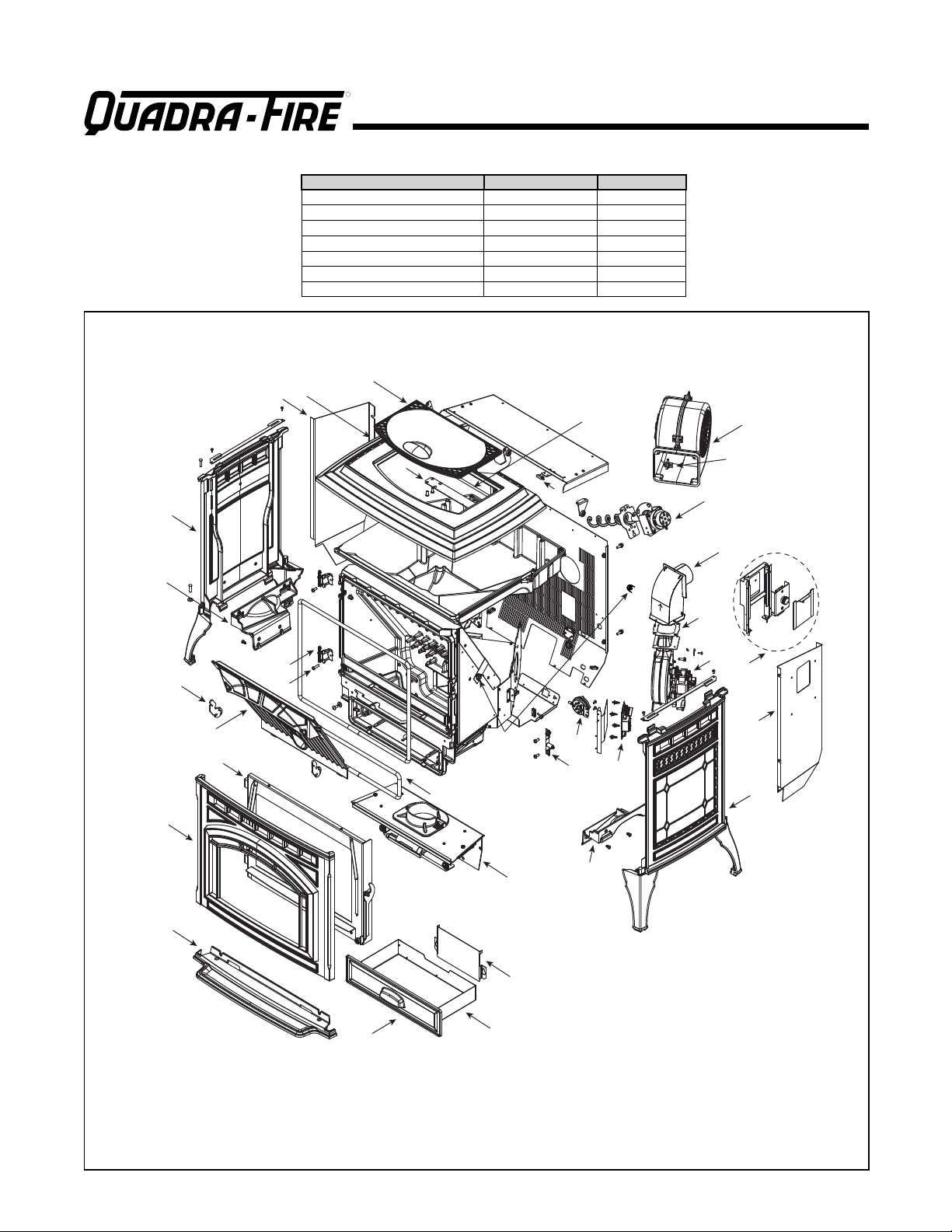
A. Sample of Serial Number / Safety Label
LOCATION:BackofStove
Serial No.
Model
Name
Test Lab &
Report No.
Mfg. Date
SAMPLE
NOTE: Clearances may only be reduced by means approved by the regulatory authority having
jurisdiction
and Welcome to the Quadra-Fire Family!
301/247080-803J
TABLE OF CONTENTS
Safety Alert Key:
DANGER!Indicatesahazardoussituationwhich,ifnotavoidedwillresultindeathorseriousinjury.
WARNING!Indicatesahazardoussituationwhich,ifnotavoidedcouldresultindeathorseriousinjury.
CAUTION!Indicatesahazardoussituationwhich,ifnotavoided,couldresultinminorormoderateinjury.
NOTICE:Indicatespracticeswhichmaycausedamagetotheapplianceortoproperty.
Quadra-FireisaregisteredtrademarkofHearth&HomeTechnologies.
A.SampleofSerialNumber/SafetyLabel........... 2
B.WarrantyPolicy.............................. 4
C.QuickStartGuide............................. 6
1 Listing and Code Approvals
A.ApplianceCertication......................... 7
B.BTU&E󰀩ciencySpecications .................. 7
C.GlassSpecications........................... 8
D.ElectricalRating.............................. 8
E.MobileHomeApproved........................ 8
F.SleepingRoom ............................... 8
G.California-Prop65............................ 8
2 Operating Instructions
A.FireSafety.................................. 9
B.Non-CombustibleMaterials..................... 9
C.CombustibleMaterials ......................... 9
D.FuelMaterialandFuelStorage.................. 9
E.BeforeYourFirstFire ......................... 10
F.FillingtheHopper............................ 10
G.UserDialControl ............................ 10
H.NormalStartupSequence..................... 10
I.FirepotPurge............................... 11
J.Shutdown.................................. 11
K.FireCharacteristics.......................... 11
L.GeneralOperatingofAppliance ................. 11
M.RestartingtheAppliance...................... 11
N.ClearSpace ................................ 12
O.TrimAdjustment............................. 12
P.LEDColorCodingChartandExplanation......... 13
Q.ThermostatControls......................... 14
R.ThermostatSetupOptions ..................... 14
S.ThermostatOperationInstructions............... 15
T.ThermostatTemperaturePrograms.............. 15
U.ThermostatOtherFeatures.................... 16
V.ThermostatBatteryReplacement................ 17
W.FrequentlyAskedQuestions ................... 18
3 Maintenance and Service
A.ProperShutdownProcedure................... 19
B.QuickReferenceMaintenanceChart............. 19
C.GeneralMaintenanceandCleaning............. 20
D.SootorCreosoteFireAwareness............... 23
E.HighAshFuelContentMaintenance............. 24
F.Ba󰀪eRemoval .............................. 24
G.GlassReplacement .......................... 24
H.ConvectionBlowerReplacement................ 25
I.Combustion/ExhaustBlowerReplacement ......... 25
4 Troubleshooting Guide
A.GeneralAppliance........................... 26
5 Reference Materials
A.ComponentFunctions........................ 30
B.MaintenanceLog............................ 32
C.ServicePartsList............................ 33
=Containsupdatedinformation
401/247080-803J
B. Warranty Policy
Hearth & Home Technologies LLC
LIMITED LIFETIME WARRANTY
Hearth & Home Technologies LLC (“HHT”) extends the following warranty for HHT gas, wood, pellet and electric hearth appliances
(each a “Product” and collecvely, the “Product(s)”) and certain component parts set forth in the table below (“Component Part(s)”)
that are purchased from a HHT authorized dealer or distributor.
WARRANTY COVERAGE:
HHT warrants that the Products and their Component Parts will be free from defects in materials and workmanship for the applicable
period of Warranty coverage set forth in the table below (“Warranty Period”). If a Product or Component Parts are found to be
defecve in materials or workmanship during the applicable Warranty Period, HHT will, at its opon, repair the applicable Component
Part(s), replace the applicable Component Part(s), or refund the purchase price of the applicable Product(s). The maximum amount
recoverable under this Warranty is limited to the purchase price of the Product. This Warranty is transferable from the original purchaser
to subsequent owners, but the Warranty Period will not be extended in duraon or expanded in coverage for any such transfer. This
Warranty is subject to condions, exclusions, and limitaons as described below.
WARRANTY PERIOD:
Warranty coverage begins at the date of installaon. In the case of new home construcons, Warranty coverage begins on the date of
rst occupancy of the dwelling or six months aer the sale of the Product(s) by an independent, authorized HHT dealer or distributor,
whichever occurs earlier. However, the Warranty coverage shall commence no later than 24 months following the date of Product
shipment from HHT, regardless of the installaon or occupancy date.
The term “Lifeme” in the table below is dened as: 20 years from the beginning date of warranty coverage for gas appliances, 10 years
from the beginning date of warranty coverage for wood and pellet appliances, and 5 years from the beginning of warranty coverage
for standalone gas log sets. These me periods reect the minimum expected useful lives of the designated Component Parts under
normal operang condions.
Page 1 of 2
4021-645M 9/21
Component
Parts Labor Gas Pellet Wood Electric Venting Component Parts Covered by this Warranty
XAll parts except as covered by Warranty Conditions,
Warranty Exclusions, and Warranty Limitations listed
X X Igniters, Auger Motors, Electronic Components, and
Glass
X
Electrical components limited to modules, remotes/wall
switches, valves, pilots, blowers, junction boxes, wire
harnesses, transformers and lights (excluding light bulbs)
X X Molded Refractory Panels, Glass Liners
X
(Vented and Vent Free gas log sets not sold as
X
X X Castings, Medallions and Baffles
6 years 3 years XCatalysts
7 years 3 years X X Manifold tubes, HHT Chimney and Terminations
10 years 1 year X
Limited
Lifetime 3 years XXX Firebox and heat exchanger, FlexBurn® System
(engine, inner cover, access cover and fireback)
1 Year None XXXXX All purchased replacement parts
Warranty Period HHT Manufactured Appliances and Venting
All parts including handles, external enameled
components and other material except as covered by
Warranty Conditions, Warranty Exclusions, and
Warranty Limitations listed
2 years
X
1 Year X X X
2 Years
5 years 1 year
Firepots, burnpots, mechanical feeders/auger
assemblies
3 years X
5 years
501/247080-803J
WARRANTY CONDITIONS:
Because HHT cannot control the quality of any Products sold by unauthorized sellers, this Warranty only covers Products that are
purchased through an HHT authorized dealer or distributor unless otherwise prohibited by law; a list of HHT authorized dealers
is available on the HHT branded websites.
This Warranty is only valid while the applicable Product remains at the site of original installaon.
This Warranty is only valid in the country in which the HHT authorized dealer or distributor that sold the applicable Product is
authorized to sell applicable Product.
Contact your installing distributor or dealer for Warranty service. If the installing dealer or distributor is unable to provide
necessary parts, contact the nearest HHT authorized dealer or supplier. Addional service fees may apply if you are seeking
Warranty service from a dealer other than the dealer from whom you originally purchased the applicable Product.
No HHT consumer should bear cost of warranty service or costs incurred while servicing warranty claims (i.e., travel, gas, or
mileage) when the service is performed within the terms of this Warranty. Check with your dealer or distributor in advance for
any costs to you when arranging a warranty call. Travel and shipping charges for parts are not covered by this Warranty.
WARRANTY EXCLUSIONS:
This Warranty does not cover the following:
Changes in surface nishes as a result of normal use. As a heang appliance, some changes in color of interior and exterior surface
nishes may occur. This is not a aw and is not covered under the Warranty.
Damage to printed, plated, or enameled surfaces caused by ngerprints, accidents, misuse, scratches, melted items or other
external sources and residues le on the plated surfaces from the use of abrasive cleaners or polishes.
Repair or replacement of parts that are subject to normal wear and tear during the Warranty Period are not covered. These parts
include: paint, wood and pellet gaskets, rebricks, grates, ame guides, baeries and the discoloraon of glass.
Minor expansion, contracon, or movement of certain parts causing noise. These condions are normal and complaints related to
this noise are not covered by this Warranty.
Damages resulng from: (1) failure to install, operate, or maintain the applicable Product in accordance with the installaon
instrucons, operang instrucons, and lisng agent idencaon label furnished with the applicable Product; (2) failure to
install the applicable Product in accordance with local building codes; (3) shipping or improper handling; (4) improper operaon,
abuse, misuse, connued operaon with damaged, corroded or failed components, accident, or improperly/incorrectly performed
repairs; (5) environmental condions, inadequate venlaon, negave pressure, or draing caused by ghtly sealed construcons,
insucient make-up air supply, or handling devices such as exhaust fans or forced air furnaces or other such causes; (6) use of fuels
other than those specied in the operaon instrucons; (7) installaon or use of components not supplied with the applicable
Product or any other components not expressly authorized and approved by HHT; (8) modicaon of the appliance not expressly
authorized and approved by HHT in wring; and/or (9) interrupons or uctuaons of electrical power supply to the applicable
Product.
Non-HHT venng components, hearth connecons or other accessories used in conjuncon with the applicable Product.
Any part of a pre-exisng replace system in which an insert or a decorave gas applicable Product is installed.
HHT’s obligaon under this Warranty does not extend to the Products capability to heat the desired space. Informaon is provided
to assist the consumer and the dealer in selecng the proper Product for the applicaon. Consideraon must be given to the
Product locaon and conguraon, environmental condions, insulaon and air ghtness of the structure.
This warranty is void if:
The applicable Product has been over-red, operated in atmospheres contaminated by chlorine, uorine, or other damaging
chemicals. Over-ring can be idened by, but not limited to, warped plates or tubes, deformaon/warping of interior cast iron
structure or components, rust colored cast iron, bubbling, cracking and discoloraon of steel or enamel nishes.
The applicable Product is subjected to prolonged periods of dampness or condensaon.
There is any damage to the applicable Product due to water or weather damage which is the result of, but not limited to, improper
chimney or venng installaon.
LIMITATIONS OF REMEDIES AND LIABILITY:
EXCEPT TO THE EXTENT PROVIDED BY LAW, HHT MAKES NO EXPRESS WARRANTIES OTHER THAN THE WARRANTY SPECIFIED
HEREIN. The owners exclusive remedy and HHT’s sole obligaon under this Warranty or in contract, tort or otherwise, shall be
limited to replacement of the Component Part(s), repair of the Component Part(s), or refund of the original purchase price of the
applicable Product(s), as specied above; provided, however, that (i) if HHT is unable to provide replacement of the Component
Part(s) and repair of the Component Part(s) is not commercially praccable or cannot be mely made, or (ii) the customer is
willing to accept a refund of the purchase price of the applicable Product(s), HHT may discharge all such obligaons by refunding
the purchase price of the applicable Product. In no event will HHT be liable for any incidental or consequenal damages caused
by defects in the applicable Product. Some States do not allow the exclusion or limitaon of incidental or consequenal damages,
so the above limitaon or exclusion may not apply to you. This Warranty gives you specic legal rights and you may also have
other rights which vary from State to State. THE DURATION OF ANY IMPLIED WARRANTY IS LIMITED TO DURATION OF THE
EXPRESSED WARRANTY SPECIFIED ABOVE FOR THE APPLICABLE PRODUCT. Some States do not allow limitaons on how long an
implied warranty lasts, so the above limitaon may not apply to you.
Page 2 of 2
4021-645M 9/21
601/247080-803J
April05,2021
QUICK START GUIDE
*Beforeyoupluginthisappliance,followtheseinstructions*
Prime
1. Aftertheexhaustblowerhasstopped;quicklyturnthedialfromOFFtoHItwotimes:
H
E
A
T
S
E
T
T
I
N
G
H
E
A
T
S
E
T
T
I
N
G
O
F
F
HI
LO
H
E
A
T
S
E
T
T
I
N
G
H
E
A
T
S
E
T
T
I
N
G
O
F
F
HI
LO
H
E
A
T
S
E
T
T
I
N
G
H
E
A
T
S
E
T
T
I
N
G
O
F
F
HI
LO
• TheLIGHTwillturnsolidgreenandpelletswillfeed.Waitfor2minutes
• IftheLIGHTdidnotturnsolidgreen:
- TurndialbacktoOFF
- Unplugappliance,plugitbackinandrepeat
Priming is only needed for fi rst fi re or starting fi re on empty hopper.
NOTE: The prime function is only required during initial set up of the unit, or after the unit has
alarmedoutduetoanemptyhopper.Primingwhileundernormaloperatingconditionswillcause
therepottooverll.
SetUp
1. Empty re box of
componentpacketand
anyotherdebris.
Run
1. WhilethermostatisinRUNmode,the
set temperature can be temporarily
changedbypressingUP.
2. ChooseSetting:
Light
H
E
A
T
S
E
T
T
I
N
G
H
E
A
T
S
E
T
T
I
N
G
0
-
1
-
2
-
3
-
4
+
1
+
2
+
3
+
4
O
N
A
L
A
R
M
O
F
F
HI
LO
Dial
Trim
Control Panel
*The temporarily changed set temperature
willreturntotheprogrammedvaluestoredin
memorywhenstarttimeofthenextupcoming
scheduled event is reached (MORN, DAY,
EVE,ORNITE).
**Appliance will not turn on unless target
temperatureisahighertemperaturethanthe
roomtemperature.
*For rst re, HHT
recommends running on HI
forrst30minutes
It may take as long as 10
minutes to achieve a re in
therepot.Turningthe knob
orthermostattoo󰀨duringthis
time will interrupt the startup
process.
• LO–HI*
• GreenLIGHTwillbegin
ashing and stove will
start
2. Add pellets and close
lid.
3.TurnDIALtoOFF
4.Plugintheappliance
• Exhaustblowerwillrunforabout45
Seconds (wait for it to stop before
priming)
• Greenlightwillstartashing
5.Ensurethermostatisconnectedproperly
perincludedinstructions.
C. Quick Start Guide
701/247080-803J
Thispelletapplianceneedsperiodicinspectionandrepair
for proper operation. It is against federal regulations to
operatethispelletapplianceinamannerinconsistentwith
theoperatinginstructionsintheowner’smanual.
A. Appliance Certication
NOTICE:Thisinstallationmustconformwithlocalcodes.
Intheabsenceoflocalcodesyoumustcomplywiththe
ASTM E1059-12, ULC S627-00, (UM) 84-HUD and
ULC/ORD-C-1482.
B. BTU & E󰀩ciency Specications
EPA Certication Number: Number:98-17
EPA Certied Emissions: 0.74gramsperhour
*LHV Tested E󰀩ciency: 83.2%
**HHV Tested E󰀩ciency: 77.9%
***EPA BTU Output: 12,682to39,428/hr.
****BTU Input: 16,396to50,775/hr.
Vent Size: 3”or4”Type“L”or“PL”
Hopper Capacity: 80lbs.
Fuel: PremiumWoodPellets
*WeightedaverageLHV(LowHeatingValue)e󰀩ciency
using data collected during EPA emissions tests in
accordancewiththerequirementsofCSAB415.1.
**WeightedaverageHHV(HighHeatingValue)e󰀩ciency
using data collected during EPA emissions tests in
accordancewiththerequirementsofCSAB415.1.
***ArangeofBTUoutputscalculatedusingHHVe󰀩ciency
andtheburnratesfromtheEPAtests.
****Basedonthemaximumfeedrateperhourmultiplied
byapproximately8600BTU’swhichistheaverageBTU’s
fromapoundofpellets.
1 1 Listing and Code Approvals
The Trekker is Certied to comply with
2020particulateemissionstandards.
Model: TrekkerPelletStove
Laboratory: OMNITestLaboratories,Inc.
Report No: 061-S-83-2,0061PS094E
Type: Solid Fuel Room Heater, Pellet Fuel
BurningType
Standard(s): ASTM E1509-12, ULC S627-00 and
(UM)84-HUD,MobileHomeApproved.
Can be found at:
www.quadrare.com/about-us/epa-certication
801/247080-803J
NOTE: Hearth & Home Technologies, manufacturer of
this appliance, reserves the right to alter its products,
theirspecicationsand/orpricewithoutnotice.
Improper installation, adjustment, alteration, service or
maintenancecancauseinjuryorpropertydamage.
Forassistanceoradditionalinformation,consultaqualied
installer,serviceagencyoryourdealer.
C. Glass Specications
This stove is equipped with 5mm ceramic glass. Replace
glass only with 5mm ceramic glass. Please contact your
dealerforreplacementglass.
D. Electrical Rating
115VAC,60Hz,Start2.9Amps,Run2.45Amps
E. Mobile Home Approved
• Thisapplianceisapprovedformobilehomeinstallations
when not installed in a sleeping room and when an
outsidecombustionairinletisprovided.
• Thestructuralintegrityofthemobilehomeoor,ceiling,
andwallsmustbemaintained.
• Theappliancemustbeproperlygroundedtotheframe
ofthemobilehomeanduseonlyListedpelletventClass
“L”or“PL”connectorpipe.
• OutsideAir Kit (OAK-3) must be installed in a mobile
homeinstallation.
F. Sleeping Room
Wheninstalledinasleepingroomitisrecommendedthat3ft
ofverticalbeinstalledpriortohorizontallyexitingtheroom
andasmoke/COalarmbeinstalledinthebedroom.Thesize
of the room must be at least 50ft³ per 1,000 Btu/hr stove
input, if the stove exceeds the room size, out air must be
installed.
G. California - Prop65
This product and the fuels used to operate this product (wood), and the
products of combustion of such fuels, can expose you to chemicals
including carbon black, which is known to the State of California to
cause cancer, and carbon monoxide, which is known to the State of
California to cause birth defects or other reproductive harm. For more
information go to: WWW.P65Warnings.ca.gov
WARNING
Installationanduseofanydamagedappliance.
Modicationoftheappliance.
InstallationotherthanasinstructedbyHearth&
HomeTechnologies.
Installationand/oruseofanycomponentpartnot
approvedbyHearth&HomeTechnologies.
Operatingappliancewithoutfullyassembling
allcomponents.
Operatingappliancewithoutlegsattached(if
suppliedwithunit).
DoNOTOverre-Ifapplianceorchimney
connectorglows,youareoverring.
Anysuchactionthatmaycausearehazard.
WARNING
Fire Risk.
Hearth&HomeTechnologiesdisclaimsany
responsibilityfor,andthewarrantywillbe
voidedby,thefollowingactions:
901/247080-803J
Visit www.quadrare.com/shopping-tools/videos to view
productanduse&carevideos.
A. Fire Safety
To provide reasonable re safety, the following should be
givenseriousconsideration:
• Installatleastonesmokedetectoroneachoorofyour
home.
• Install at least one carbon monoxide detector on each
oorofyourhome.
• Locatesmokedetectorawayfromtheheatingappliance
andclosetothesleepingareas.
• Follow the smoke detector manufacturer’s placement
andinstallationinstructionsandmaintainregularly.
• Followthecarbonmonoxidemanufacturer’splacement
andinstallationinstructionsandmaintainregularly.
• ConvenientlylocateaClassAreextinguishertocontend
withsmallres.
• Intheeventofahopperre:
- Evacuatethehouseimmediately.
- Notifyredepartment.
B. Non-Combustible Materials
Material which will not ignite and burn, composed of any
combinationofthefollowing:
- Steel
- Plaster
- Glass
- Tile
- Brick
- Iron
- Slate
- Concrete
Materials reported as passing ASTM E 136, Standard
Test Method for Behavior of Metals, in a Vertical Tube
Furnace of 750° C.
Fire Risk.
Donotoperateappliancebeforereading
andunderstandingoperatinginstructions.
Failuretooperateapplianceproperlymay
causeahousere.
C. Combustible Materials
Material made of/or surfaced with any of the
followingmaterials:
- CompressedPaper
- Wood
- Plywood/OSB
- SheetRock(drywall)
- Plastic
- PlantFibers
Any material that can ignite and burn:ameproofedor
not,plasteredornon-plastered.
D. Fuel Material and Fuel Storage
Pelletfuelqualitycangreatlyuctuate.Werecommendthat
youbuyfuelinmulti-tonlotswheneverpossible.However,
wedorecommendtryingvariousbrandsbeforepurchasing
multi-tonlotstoensureyoursatisfaction.
Fuel Material
• Madefromsawdustorwoodby-products
• Dependingonthesourcematerialitmayhaveahighor
lowashcontent.
Higher Ash Content Material
• Hardwoodswithahighmineralcontent
• Fuelthatcontainsbark
• Standardgradepelletsorhighashpellets
Lower Ash Content Material
• Mostsoftwoods
• Fuelswithlowmineralcontent
• Mostpremiumgradepellets
Clinkers
Mineralsandothernon-combustiblematerialssuchassand
will turn into a hard, glass-like substance called a clinker
whenheatedintherepot.
Treesfromdi󰀨erentareaswillvaryinmineralcontent.That
iswhysomefuelsproducemoreclinkersthanothers.
Moisture
Alwaysburndryfuel.Burningfuelwithhighmoisturecontent
takes heat from the fuel and tends to cool the appliance,
robbingheatfromyourhome.Damppelletfuelcanclogthe
feedsystem.
2 2 Operating Instructions
WARNING
10 01/247080-803J
F. Filling the Hopper
Openthehopperlidbyliftingthehandle.Fillthehopperwith
fuel.Closethehopperlid.Theappliancewillnotfeedwith
thehopperlidopenandtherewillgoout.
Odors and vapors released during initial operation.
Curingofhightemperaturepaint.
Openwindowsforaircirculation.
Odorsmaybeirritatingtosensitiveindividuals.
Storage
• Woodpelletsshouldbeleftintheiroriginalsealedbag
untilusingtopreventmoistureabsorption
• Do not store any pellet fuel within the clearance
requirements or in an area that would hinder routine
cleaningandmaintenance.
E. Before Your First Fire
1. First, make sure your appliance has been properly
installedandthatallsafetyrequirementshavebeenmet.
Payparticularattentiontothereprotectionandventing.
2. Doublecheckthatthereboxisemptyandtherepot
oorisfullyclosed.
3. Closeandlatchthedo
Size
• Pellets are either 1/4 inch or 5/16 inch (6-8mm) in
diameter
• Lengthshouldbenomorethat1-1/2inches(38mm)
• Pellet lengths can vary from lot to lot from the same
manufacturer
• Duetolengthvariations,thefeedratemayneedadjusting
occasionally
Performance
• Higher ash content requires the re pot and the ash
drawertobeemptiedmorefrequently
• Hardwoodsrequiremoreairtoburnproperly
• Premiumwoodpelletsproducethehighestheatoutput
• Burning pellets longer than 1-1/2 inches (38mm) can
cause an inconsistent fuel feed rate and/or missed
ignitionsorfeedjams.
Tested and approved for wood pellets. Burning of any
othertypeoffuelvoidsyourwarranty.
CAUTION
CAUTION
G. User Dial Control
Theappliancehasonedialcontrollocatedonthesideofthe
appliance(behindadropdoor)usedforchangingtheheat
setting and restarting the appliance. There are ve heat
settings on this dial ranging to include: LOW, MED-LOW,
MED,MED-HIGH,andHIGH. Figure 10.1
Turnthedialcontroltothedesiredheatsettingandturnthe
applianceONandOFFusingthethermostat.
Figure 10.1
H
E
A
T
S
E
T
T
I
N
G
H
E
A
T
S
E
T
T
I
N
G
0
-
1
-
2
-
3
-
4
+
1
+
2
+
3
+
4
O
N
A
L
A
R
M
O
F
F
HI
LO
H. Normal Startup Sequence
Theappliancewillgointotheignitionsequencefollowedby
astartupsequence(thegreenLEDwillashrapidly).
The ignition sequence involves the exhaust blower and
igniterturningon,andthefeedmotorrunningintwostages.
Therststageinvolvesthefeedmotorrunningcontinuously
foraboutaminutetostartloadingpelletsintotherepot.
In the second stage, the feed motor will begin cycling on
ando󰀨.
Whenthepelletsarewarming-onthevergeofigniting-itis
notuncommonforthereboxtollwithsmoke.
Onceignitionhappens,thesmokeshouldquicklydisappear.
During this stage, as well as any part during the burn
process,thefrontdoorshouldnotbeopened.
This startup cycle continues until the appliance senses
ignitionbyariseintheexhausttemperatureortheappliance
times out. Following the ignition cycle the appliance
continuestofeedpelletstobuildupthere.
Afterwarmingup,theconvectionblowerwillbegintoblow
warmairintotheroom.Astheapplianceincreasesheatthe
blowerwillincreaseitsoutput.
11 01/247080-803J
K. Fire Characteristics
Theoverallheightoftheamewillvarythroughouttheburn
foracoupleofreasons:
1. Theamewillvarybasedontypeoffuelorbatchoffuel.
2. The appliance adjusts the burn rate according to the
dialsetting–thefurtherthedialisrotatedclockwisethe
highertheameandconsequently,heatoutput.
NOTICE: If you expect children to come into contact
withthisappliance,werecommendabarriersuchas a
decorativescreen.Seeyourretailerforsuggestions.
I. Fire pot Purge
Purpose:Tohelpremovedebrisfromtherepotandhelp
theapplianceburnase󰀩cientaspossible.
Thefrequencyofthepurgecycleisonceevery30minutes
whiletheapplianceisburning.Duringtherepotpurge,the
feedisreducedtothelowestsettingandtheexhaustblower
rampsuptoaveryhighsetting.Thepurgecyclelasts99
seconds.
The purge cycle does not replace daily cleaning.
J. Shutdown
Toshuttheappliancedown,turnthedialcontroltoOFFor
turnthethermostattoOFF.Duringtheshutdownprocess,
thelightwillashamberorgreenrapidly.
Unliketherepotpurge,duringshutdownexistingfuel in
therepotwillcontinuetoburnwithoutthefeedmotorrun-
ning;but,the exhaustandconvectionblowerswill remain
onuntiltheexhausthascooled.
NOTE: If maintenance or daily cleaning is going to be
conducted immediately following a shutdown, please use
cautionascomponentsespeciallythoseinsidetherebox
maystillbehot.
Duetosafetyprecautions:
• IfthedialcontrolisturnedtoOFFandbackon(evenif
bymistake)theappliancewillgothroughtheshutdown
sequencebeforerestarting.
• Additionally,ifthethermostatisturnedto“OFF”during
operation the appliance will go through a shutdown
sequencebeforerestarting.
NOTE: If maintenance or daily cleaning is going to be
conductedimmediatelyfollowingashutdown,pleaseuse
cautionascomponentsespeciallythoseinsidetherebox
maystillbehot.
L. General Operating of Appliance
Ash Dump Lever
Baffle Latch
Firepot
Baffle
Dial
Control
Hopper
Switch
Figure 11.1
HOT WHILE IN OPERATION. KEEP CHILDREN,
CLOTHINGAND FURNITURE AWAY. CONTACT MAY
CAUSESKINBURNS.
CAUTION
3. General maintenance and cleaning. Infrequent or poor
generalmaintenancewillresult in poorer performance.
Indicatorsforadditionalmaintenanceactivitiesinclude:
- Lazyame
- Black-sootedglass
- Pelletsnotigniting
- Excesspelletsfallingtothesideoftherepot
4. Seetrimadjustmentsectionforadditionalinformation.
M. Restarting the Appliance
RestartProcess
1. Whentheappliancehasrunoutoffuelandthe“empty
hopper” error code illuminates, add pellet fuel to the
hopper.
2. Dumptheashesandclinkersbuiltupintherepotby
pullingtheashdumpremovalhandleoutseveraltimes.
Makesureclinkershavedroppedintotheashpanthen
returnthehandletofullyclosedposition.
3. TurnthedialcontroltoOFFandthenuptohigh2Xto
prime.
4. Afterseeingpelletsdropthenturntodesiredsettingto
reset the appliance control system. The appliance will
thenbeginitsstartupsequence.
RestartingAfteraPowerFailure
1. For an electrical disruption the appliance will start on
itsownwithoutneedforpriming-providingthecontrol
systemisaskingforheat.
2. Theappliancewillalwaysgothroughanormalshutdown
sequencebeforerestarting.
12 01/247080-803J
N. Clear Space
Mantel:
Avoid placing candles and other heat-sensitive
objectsonmantelorhearth.Heatmaydamagethese
objects.
O. Trim Adjustment
Trim adjustment is the small dial located below the main
dialcontrol.Thefunctionofthetrimadjustmentistoallowfor
variationsinelevation,ventingandinstallationcongurations,
andfueltypes(hardwood/softwood).
Rotatingthisdialwilladjusttheair/fuelratiototheappliance:
• Clockwiseadjustmentsincreasetheameheight.
• Counter-clockwise adjustments will decrease the ame
height.
• Whenchanging trimsettingsonlyadjust1levelatatime,
allowing 15 minutes for re to stabilize before making
anotheradjustment.
• Thefactorydefaulttrimadjustmentsaresettozero(0)for
mostfuelsandrecommendedventingcongurations.
Aproperlyadjustedrewillhaveabright,activeamepattern
that extends out of the re pot approximately 6 to 9 inches
whenburningonhigh.Aproperlyadjustedrewillburncleaner
andhavehighere󰀩ciencies.
Figure 12.1
NOTICE: Clearances may only be reduced by means
approvedbytheregulatoryauthorityhavingjurisdiction.
WARNING
Fire Risk
Do NOT operate appliance:
• Withappliancedooropen.
• Firepotooropen.
Do NOT store fuel:
• Closer than required clearances to combustibles to
appliance
• Withinspacerequiredforloadingorashremoval.
HOT SURFACES!
Glass and other surfaces are hot during
operationANDcooldown.
WARNING
Hot glass will cause burns.
• Donottouchglassuntilitiscooled.
• NEVERallowchildrentotouchglass.
• Keepchildrenaway.
• CAREFULLY SUPERVISE children in same room
asappliance.
• Alert children and adults to hazards of
hightemperatures.
• High temperatures may ignite clothing or other
ammablematerials.
• Keep clothing, furniture, draperies and other
ammablematerialsaway.
13 01/247080-803J
LED
Color No. of Flashes
between pauses Description Notes
Green
SteadyONwhile
primingfeedtube
(maxtime
2minutes)
FeedMotorisrunning
continuously.
(primingthefeedtube)
Whenprimingthefeedsystemandllingtherepot,DO
NOTOVERFILLFirepotFORIGNITION.Theappliancewill
automaticallygointostartupfollowingtheprimefunction.
Green 1xevery2
seconds Applianceisonstandby Tostartappliance,followstartupsequence.
Green Blinks
Continuously
Applianceisinthestart
up/ignitionsequenceorin
shutdown.
Duringshutdown,theblowerswillshuto󰀨whentheexhaust
temperaturehascooled.
Green 1X Stage1:Lowheat BTURange:14,620-19,694 Average:19,054
Green 2X Stage2:Med-Lowheat BTURange:22,102-23,506 Average:22,735
Green 3X Stage3:Medheat BTURange:30,778-32,680 Average:31,603
Green 4X Stage4:Med-Hiheat BTURange:38,576-42,914 Average:40,665
Green 5X Stage5:Hiheat BTURange:49,830-52,460 Average:51,528
Amber Blinks
Continuously
Applianceisinthe
shutdownsequence.
Duringshutdown,theblowerswillshuto󰀨whentheexhaust
temperaturehascooled.
Red 1X EmptyHopperAlarm Thisalarmiscausedbytheregoingoutfromlackoffuel.
Resetbyturningto“OFF”thenturndialtodesiredsetting.
Red 2X ExhaustProbeAlarm Failedcomponenterror.Seetroubleshootingsectionfor
moreinformation.
Red 4X MissedIgnition
Thereareatotalof2triesperignitionsequence.Ifafter
2triesthereisnoriseinexhausttemperaturethiserror
willoccur.Seethetroubleshootingsectionforadditional
information.
Red 6X EncoderAlarm FailedComponentError:ExhaustSpeedSensor.See
troubleshootingguideformoreinformation
Red 8X ExhaustOver
TemperatureAlarm Seetroubleshootingguideformoreinformation.
P. LED Color Coding Chart and Explanation
Thenumberofashesisoneeverysecondunlessotherwiseindicated.
Fire Risk
DoNOToperateappliance:
Withappliancedooropen.
Firepotooropen.
DoNOTstorefuel:
Closer than required clearances to
combustiblestoappliance
Within space required for loading or ash
removal.
WARNING
14 01/247080-803J
Q. Thermostat Controls
TEMPERATURE (HEAT / OFF) SWITCH:
Setthis switchtoHEATtocontrolyourappliance.Theo󰀨
positionwilldisabletheappliance.
SET (MULTI- FUNCTION) SLIDE SWITCH:
Thisprovideseasyaccesstocommonsettings,andshould
alwaysremaininRUNunlessitemsarebeingadjusted.
NOTE: When thermostat is set to “Manual” non-
programmablemode,allpositionsoftheSETslideswitch
willactlikeRUN.
UP / DOWN BUTTONS:
The UP and DOWN buttons are used to control the set
temperature,oradjustanyotheron-screenitems.Anitems
ashing,istheitemcurrentlybeingadjusted.
HOLD BUTTON:
This button activates and deactivates the manual
Temperature HOLD feature, which maintains a xed set
temperatureindenitelywithoutfollowingaprogramroutine.
COPY BUTTON:
Thisisusedtocopytemperatureprogramitemsfromone
daytothenext.Alsousedtoaccessthemenusetup.
NEXT BUTTON:
Thisisusedwhensettingitemssuchassoftwareoptions,
andtemperature programs when they are ashingonthe
screen.PressingtheNEXTbuttonwillcyclethroughwhich
itemisashing.
Figure 14.1
R. Thermostat Setup Options
Setup options for how the thermostat will function are
performedusingamenuonthedisplayscreen.
TO ACCESS THE SETUP MENU:
Move the TEMPERATURE switch into the OFF position,
andthenholddowntheCOPYbuttonforapproximately5
seconds until the screen changes. The menu will always
startwithitem#01,andisadvancedtoeachfollowingitem
byasinglepressoftheNEXTbutton.Theoptionsforeach
itemarechangedusingtheUPorDOWNbuttons.
ITEM #01 (CLK = CLOCK FORMAT):
• 12Hr,default:Thisdisplaystheclocktimesusingstandard
AMandPMvalues.
• 24Hr:Thisdisplaystheclocktimesusingthemilitary-time
format(example22:00hours,withoutusingAMorPM).
ITEM #02 (TMP = TEMPERATURE SCALE):
• F,default:ShowsalltemperaturevaluesinFahrenheit.
• C:ShowsalltemperaturevaluesCelsius.
ITEM #03 (PROGRAMMING STYLE):
• 7Day,default:Thisstyleusesaseparateprogramroutine
foreachofthe7daysintheweek.
• 5/2Day:Thisstyleusesaweekdayprogramroutinefor
Monday, Tuesday, Wednesday, Thursday, Friday, and
aseparateweekendprogramroutine for Saturdayand
Sunday.
• Manual Non-Programmable: In this setting, there are
noprogramroutinesforthethermostattofollowandthe
temperaturecontrolwillbesetonlybytheUPandDOWN
buttonsonthefrontpanel.
ITEM #04 (PERD = EVENT OR PERIOD QUANTITY):
• 4P,default:ThermostatusesfourEventsperday(called
MORN,DAY,EVE, and NITE).
• 2P:ThethermostatusestwoEventsperday(calledDAY
and NITE).
NOTE: Eventor PeriodQuantityfeatureisnotaccessible
duringManualNon-Programmablemode.
ITEM #07 (DLAY = DELAY TIME):
• 5, default: Thermostat waits 5 minutes before turning
the system back on after it was last run. This internal
delaypreventstheappliancefromturningontooquickly
aftershuttingdown.The5minutesettingisneformost
applications.
• 2:Sameoperationasabove but reduced to 2minutes
betweenstatechanges.
NOTE: Thereisnodelayavailablewhenthethermostatis
manuallyturnedupanddown.
15 01/247080-803J
ITEM #08 (TEMPERATURE DIFFERENTIAL):
• Thethermostatworksbyturningyourheatingsystemon
ando󰀨whenevertheroomtemperaturevariesfromthe
desiredset-pointtemperature.
• UsetheUP/DOWNbuttonstochangethenumbervalue
between 1 and 9. Generally your system should cycle
on about 3 to 6 times per hour.A smaller di󰀨erential
numbermakesthesystemcyclemorefrequently,sothe
roomtemperatureismorepreciseandconstant.Alarger
di󰀨erentialnumberwillmakethesystemremainonfora
longerdurationeachtimeanddecreasesthenumberof
cyclesperhour.
• Defaultissetto4.
S. Thermostat Operation Instructions
SET DAY AND TIME:
PlacetheSETswitchintotheDAY/TIMEposition.Withthe
dayashingpressUPorDOWNtosetthedayortheweek.
PressNEXTandtheclocktimewillstartashing.UseUPor
DOWNtosetthetime;verifytheAM/PMindicatoriscorrect.
ReturntheSETswitchtoRUNpositionwhennished.
HEATING:
Basic operation of the thermostat can be obtained with
the SET switch in the RUN position. The temperature
canbeadjustedusing the UPandDOWN buttons.When
the thermostat is rst powered on, it will follow a default
temperatureroutinethatispresetfromthefactory(Figure
15.1).
LCD DISPLAY BACK LIGHT:
Figure 15.1
Event Time Temperature
MORN 6:00AM 70°F(21°C)
DAY 8:00AM 62°F(17°C)
EVE 6:00PM 70°F(21°C)
NITE 10:00PM 62°F(17°C)
T. Thermostat Temperature Programs
Thethermostatbydefaulthas4separateprogramevents
theyare:MORN,DAY,EVE,andNITE.Eacheventendsat
thestarttimeofthefollowingevent.
6. Usesteps3through5tosetuptheeventsfortherestof
theweekorgroupofdays.
7. ReturntheSETswitchbacktoRUN.
NOTE:Whenthelasteventisnishedforeachdayor
groupofdays,thethermostat willadvanceforwardinto
thenextdayorgroupofdays.
SET TEMPERATURE PROGRAMS:
1. MoveTEMPERATUREswitchtoHEAT.
2. MoveSETswitchtoTEMPPROGposition.
3. StartingwithMonday,usetheUPorDOWNbuttonsto
adjustthestarttimeandsettemperaturefortheMORN
event,andthenpressNEXTbuttontoadvance.
4. Adjust the start time and set temperature of the DAY
eventthenpressNEXTbutton.
5. Continue in this same manner to adjust the start time
andsettemperaturesfortheEVEandNITEeventsfor
Monday.
NOTE:Ifthethermostatissetfor2eventsadayinstead
of 4, the thermostat will only use the DAY and NITE
events.
TEMPERATURE HOLD:
Temperature hold is used for maintaining a xed set
temperature;onceaHOLDisinitiated,thethermostatwill
maintainthesettemperatureindenitely.ToenteraHOLD
state,presstheHOLDbuttononetimeandthewordHOLD
willappearonthedisplay.Tocancel,presstheHOLDbutton
onceagain.
Thedisplayscreenislightedtoassistviewingatnighttime,
orinlocationswithlowlightlevels.Pressanybuttononthe
frontpaneltoactivatetheapproximate10secondbacklight.
TEMPERATURE OVERRIDE:
While thermostat is in RUN mode, the set temperature
can be temporarily changed by pressing UP or DOWN.
The temporarily changed set temperature will return to
the programmed value stored in memory when start time
ofthenextupcomingscheduledeventisreached(MORN,
DAY, EVE, OR NITE). While the temporary changed set
temperatureisine󰀨ect,thewordOVERRIDEwillbeshown
on the display screen. To cancel, move TEMPERATURE
switchtoOFFandbacktoHEATagain.
STATIC NOTICE
Thermostat is protected against normal static electric
discharges, however to minimize the risk of damaging
thethermostatinextremelydryweather,pleasetoucha
groundedmetalobjectbeforetouchingthethermostat.
16 01/247080-803J
COPY PROGRAM FEATURE:
Using similar instructions as SET TEMPERATURE
PROGRAMS the COPYbuttonwillallowawholedayof
setprogrameventstobecopiedtoanotherday.
1. MoveTEMPERATUREswitchtoHEATaswellasmove
SETswitchtoTEMPPROGposition.
2. StartingwithMonday,usetheUPorDOWNbuttonsto
adjustthestarttimeandsettemperaturefortheMORN,
DAY, EVE, and NITE events. Press the COPY button
andthenpresstheNEXTbuttontoadvancetoTuesday.
3. With Tuesday displayed press COPY button. As
all programs events from Monday will be copied to
Tuesday (this will advance automatically to the next
day;Wednesday,asthewordCOPYwillappearonthe
screenforonesecond).
4. Continue in this pressing COPY button to set desired
dayswithoriginalsetting.
NOTE: The word COPY will not appear on the display
for Monday, but will display each day afterwards for
approximatelyonesecondandthedayoftheweekwill
automaticallyadvanceforwardtothenextday.
U. Thermostat Other Features
NOTE: Allotherfeaturesneedtobecompletedinatimely
mannerasthethermostatwilltimeoutafter10seconds.
TEMPERATURE CALIBRATION:
The internal temperature sensor in this thermostat is
accurately calibrated at the factory, and in most cases
alterations to this setting should not be needed. The
temperaturecalibrationfeatureallowsyoutomanuallyo󰀨set
themeasuredtemperaturebyasmuchasplusorminus5°F
(3°C)fromitsoriginalvalue.Ifseveralthermostatsareused
inthesamehouse,thisfeaturecanbeusedtosynchronize
thisthermostattotheothers.
Change the temperature calibration:
1. MoveTEMPERATUREswitchtoOFF.
2. MoveSETswitchtoRUN.
3. PressandholdbothUPandDOWNbuttonstogetherfor
atleast5seconds;thewordsSETandCALwillappear
onthedisplayalongwitha single ashing temperature
digit.
4. UsetheUPorDOWNbuttonstochangethenumberof
degrees desired for adjustment; 0° is the default value
andalsomeansnocorrectionwillbeapplied.
5. PresstheNEXTbuttontoacceptthesetting.
HW
RST
Figure 16.1
KEYPAD LOCKOUT:
Thereistheoptiontolockthefrontpanelbuttonstoprevent
unauthorizedtamperingofyourthermostatsettings.
To Lock the Keypad:
1. MoveTEMPERATUREswitchtoHEAT.
2. MoveSETswitchtoRUN.
3. Perform a single press of each button in the following
sequence:
• NEXT,NEXT,NEXT,HOLD
Apadlockwillappearonthedisplayscreen.
To Unlock the Keypad:
1. MoveTEMPERATUREswitchtoHEAT.
2. MoveSETswitchtoRUN.
3. Perform a single press of each button in the following
sequence:
• NEXT,NEXT,NEXT,HOLD
Apadlockwillnolongerbepresentonthedisplayscreen.
HARDWARE RESET:
The hardware reset button; labeled HW RST, is a small
roundpushbuttonthatislocatedinthemiddleofthecircuit
board,justbelowthebatteryholder(Figure 16.1).Pressing
thisbuttonwill:
• CausetheLCDdisplayscreentobecomefullypopulated
• Thermostat to perform an internal system check of its
components
Ifthethermostatappearstobeactinginanerraticmanner,
pressing the HW RST button may remedy this behavior.
Thetemperatureprogramsarenoterasedwhenahardware
reset is performed, however the clock will have to be
changedtomatchthecurrentdayandtime.
17 01/247080-803J
SOFTWARE RESET:
Software reset is used to eraseALL temperature events,
andto returnalluser-adjustablesoftwaresettingsbackto
theiroriginalfactorydefaultsettings.
ToPerformaSoftwareReset:
1. Verifythethermostat’skeypadisnotlocked.
2. MoveTEMPERATUREswitchtoOFF.
3. Press and hold the UP, DOWN, and NEXT buttons all
atthesametimeforatleast5seconds.WhentheLCD
displayscreenwill become fully populated let go of all
buttonsatthatpointthescreenwillreturntonormal.
Theclockwillhavetobechangedtomatchthecurrentday
andtime.
V. Thermostat Battery Replacement
Thisthermostatispoweredbytwo“AA”Alkalinebatteries.
The batteries should be replaced AT LEAST once per
yeartoensurereliableoperationorsooneriftheLOBATT
appearsonthedisplayscreen.Thebatteriesarelocatedon
thebackofthethermostat’scircuitboard.Thefrontportion
of the thermostat can be removed from the back half by
usingthetabsonthetopedgeof the thermostat housing
(Figure 17.1).
Figure 17.2-Fullbatteryicon
Figure 17.3-Lowbatteryicon
Figure 17.1
Wheninstallingnewbatteries,itisrecommendedusingonly
brand new “AA” size alkaline batteries. Please verify the
polaritymarkingsshowninthebatterycompartmentbefore
adding batteries to the compartment. When nished, line
upthefrontofthethermostattothebase,andrmlypress
togethertosecurelylatchthefrontandbackhalvestogether
properly.
BATTERY GRAPHIC:
Anytime time the batteries are physically present in the
thermostat,therewillbeavisualindicatorshowingthelifeof
thebattery.Thiswillappearonthedisplayscreen(Figures
17.2 & 17.3).
CONNECT THERMOSTAT WIRES TO APPLIANCE:
Thereisa4screwterminalblocklocatedonthebacklower
leftcornerofthestovedirectlyabovethepowercordinlet.
Thecenter2screwsareforthethermostatwires(Figure
17.4).
Figure 17.4
Shockhazard.
• DoNOTremovegroundingprongfromplug.
• Plug directly into properly grounded 3 prong
receptacle.
• Routecordawayfromappliance.
DoNOTroutecordunderorinfrontofappliance.
CAUTION
18 01/247080-803J
What causes my glass to become dirty?
Iftheglasshaswhiteashbuildupitisnormalandtheglassshouldbecleaned.Ifitisablacksootbuildupairowthroughthe
appliancemayberestricted.Themostoftencauseisoverduemaintenanceandcleaning.SeeMaintaining and Servicing
on page 19and/ormakeadjustmentstothetrimcontrol.
How can I get more heat out of the appliance?
Themostoftencauseofdiminishedheatoutputisoverduemaintenanceandcleaning.SeeMaintaining and Servicing on
page 19.
What should I do if I smell smoke or there is ash/soot coming from the appliance?
SealexhaustventingsystemtotheappliancewithHighTempsilicone.Securetheventingsystemtotheappliancewithat
least(3)screws.Allpelletventpipemustbesecuredtogethereitherbymeansprovidedbythepipemanufacturerorby(3)
screwsateachjoint.
Inadditionmosthomesarebuiltverytighttodayandwithexhaustsystemscancreatenegativepressureinthehome.See
Negative Pressure on page 15oftheinstallationmanual.Forashorsootchecktheaboveandtheexhaustblowerhousing
andseals.
Why would my appliance run ne last winter but not start this fall?
ItispossiblethatthestovewasnotproperlypreparedfortheNon-burnseason;seeTroubleshooting Guide starting on
page 26.
Is there a place to lubricate the blowers to quiet them down?
No.Themostoftencauseofnoisyblowersisfromtheimpellersbecomingdirtyovertime.Seemaintenanceandservice
sectionformaintainingandservicing.
What is the metal object with the bend in it that came inside the plastic bag?
Itisaclean-outtoolusedtohelpcleantherepotandremoveanyjamsintherareeventtheyoccurinthefeedtube.
Why is there a black residue building up on the outside of my home?
Windcancausethistohappen.Iftheapplianceisoperatingcorrectlyverylittlesootshouldeverexittheterminationcap.
Checktobesuretheventingisinstalledpertheowner’smanualandlocalcodes.
Do I need an outside air kit?
Outsideairisrequiredformobilehomeinstallsandinsomejurisdictions.RefertoAppliance Certications on page 3,
Mobile Home Installation on page 24oftheinstallationmanual and Appliance Set-up on page 20 of the installation
manual.Alsorefertolocalbuildingcodes.
I am seeing sparks coming out of my pipe (termination cap) outside is this safe?
Thisisnormal.Aslongasclearancestocombustibleswerefollowedthisissafe.
I have no power to anything. Does this appliance have a circuit breaker or fuse or a reset button?
Thisappliancehasonefuseonthecontrolboardandaresettablesnapdiscmountedtothefeedtube.Iftheappliance
overheatsthenthesnapdisccanbereset;ifthefuseisblownthecontrolboardmustbereplaced.
Can I burn corn in my appliance?
No,thisapplianceisnotapprovedtoburncorntypefuel.
Where is the serial # located on my appliance?
Theserialnumberislocatedonthebackofthestove.
Nopelletsaredroppinginmyrepot.
SeeTroubleshooting Guide starting on page 26.
Contact your dealer for additional information regarding operation and troubleshooting.
Visit www.quadrare.com to locate a dealer.
W. Frequently Asked Questions
19 01/247080-803J
Thispellet heaterhasamanufacturer-setminimum low
burn rate that must not be altered. It is against federal
regulationstoalterthissettingorotherwiseoperatethis
pellet heater in a manner inconsistent with operating
instructionsinthismanual.
NOTICE: Thesearerecommendations.Whenburninghighashcontentpelletfuelora/pelletmixyoumayneed
tocleantherepotseveraltimesaday.Cleanthestoveandrepotmorefrequentlyifyouencounterheavy
build-upofashattherecommendedintervaloryouseesootcomingfromthevent.Notproperlycleaningyour
applianceonaregularbasiswillvoidyourwarranty.
Follow the detailed instructions found in this section for each step listed as referenced in the chart below.
B. Quick Reference Maintenance Chart
Whenproperlymaintained,yourappliancewillgiveyoumany
yearsoftrouble-freeservice.Contactyourdealertoanswer
questions regarding proper operation, troubleshooting
and service for your appliance. Visit www.quadrare.com/
owner-resourcestoviewbasictroubleshooting,FAQs,use
&carevideos.Werecommendannualservicebyaqualied
dealer.
A. Proper Shutdown Procedure
TurndialcontroltoOFF,letappliancecompletelycooland
exhaustblowermustbeo󰀨.Aftercoolingunplugappliance
beforeservicing.
Cleaning or Inspection Frequency Daily Weekly Monthly Yearly
Firepot Asneeded OR X
AshRemovalfromFirebox About5bagsoffueldependingon
ashbuild-up OR X
Glass Whenclearviewofrepot
becomesobscure OR X
Hopper Everytonoffuel(50bags) OR X
ExhaustPath,DropTubeandBehind
Ba󰀪es
Everytonoffuel(50bags)or
morefrequently OR X
DoorHandle&GasketInspection Prior to heating season OR X
Blower,Convection Everytonoffuelormorefrequently
dependingonperformance OR X
Blower,Exhaust Everytonoffuelormorefrequently
dependingonperformance OR X
Firebox-PrepareforNon-BurnSeason Atendofheatingseason OR X
VentingSystem
Every3tonsoffuelor
morefrequentlydepending
onperformance
OR X
Table 19.1
3 3 Maintenance and Service
Shock and Smoke Hazard
• Smoke spillage into room can occur if
applianceisnotcoolbeforeunplugging.
• Risk of shock if appliance not unplugged
beforeservicingappliance.
CAUTION
20 01/247080-803J
Figure 20.2-Firepotwithlargeclinker
Clinker
Figure 20.1
C. General Maintenance and Cleaning
1. Cleaning Fire pot using Lever
• Frequency:Dailyorasneeded*
• By:Homeowner
a. Besuretheapplianceisallowedtocool.
b. Opencastfaceofappliance
c. Pullrepotoorcleaninglevertwotimesuntiltheash
fallsintotheashpanbelow(Figure 20.1).
d. Itmaybenecessarytouseyourrepotclean-outtool
tochipaway materialthathasbuilt uponthesides
ofthe re pot and topush out any clinkers (Figure
20.2).
e. Largerclinkersmayhavetoberemovedfromthetop
oftherepot.
f. Iftheclinkeradherestothesidesoftherepot,you
willneedtomanuallycleantherepot.Therepot
oorplatemustbefullyclosedwhennished.
2. Cleaning Ash Pan
• Frequency:Weeklyorevery3-5bags
• By:Homeowner
a. Locatetheashpanunderneaththerepot.
b. Slidetheashpanstraightout.
c. Emptyintoanon-combustiblecontainerandre-install
ashpan.
d. Whenreplacingashpanpushitbackuntilitcatches
onthe2sidelatches.
Clinkersllingtheashpanwillhavetobecleanedoutmore
oftenthanash.
3. Ash Disposal:
Ashes should be placed in a steel container with a tight-
ttinglid.Thecontainerofashesshouldbemovedoutdoors
immediately and placed on a non-combustible oor or on
theground,wellawayfromcombustiblematerials,pending
naldisposal.
Iftheashesaredisposedofbyburialinsoilorotherwise
locally dispersed, they should be retained in the closed
container until all cinders have thoroughly cooled. Other
wasteshallnotbeplacedinthiscontainer.
4. Ash Removal from Firebox
• Frequency: Weekly or more frequently depending on
ashbuild-up
• By:Homeowner
a. Besuretheapplianceisallowedtocool.
b. Theremustnotbeanyhotashesinthereboxduring
cleaning.
c. Frequent cleaning of the ash in the rebox with a
vacuum cleaner will help slow down the build-up of
ashintheexhaustblowerandventsystem.
WARNING
RISK OF FIRE
Keep combustible materials, gasoline and
other ammable vapors and liquids clear of
appliance.
• DoNOTstoreammablematerialsintheappliance’s
vicinity.
• DoNOTusegasoline,lanternfuel,kerosene,charcoal
lighteruidorsimilarliquidstostartor“freshenup”a
reinthisheater.
Keepallsuchliquidswellawayfromtheheaterwhileitis
inuseascombustiblematerialsmayignite.
21 01/247080-803J
Figure 21.2-Exampleofadirtyheatexchanger
Figure 21.3
NOTE:ShopVacuumandMicroCleaningKitexamples
areitemsthatcanbepurchasedatyourlocalhardware
store.
Figure 21.4
Figure 21.1
Exhaust exits must be thoroughly cleaned.
Each exit is approximately 4 inches wide, 1
inch across, and 3 inches deep
NOTE: Heavy duty vacuum cleaners may be obtained,
specicallydesignedforsolidfuelappliancecleaning.
Tools Needed: AShopVacuumandgenericmicrocleaning
kit;atheadscrewdriver;bottlebrush,anda½”IDhose.
a. Itisnecessarytoremovetheba󰀪etogainaccesstothe
heatexchanger(Figure 21.2).
b. Vacuum the ash from the heat exchanger with an
upholsterybrushtoremovethemajorityoftheash.Be
suretovacuumthebackoftheba󰀪ealso.Inspectthe
droptubeandremoveanyresiduebuild-upinthedrop
tube (Figure 21.3).
c. Assemblethecrevicetoolfromthemicrocleaningkitto
attachtoaShopVac(Figure 21.4).
d. Usethecrevicetooltonishcleaningtheheatexchanger
ns.It iscriticalthatthe2exhaustexitsatthebackof
the rebox oor (left and right) be thoroughly cleaned
(Figure 21.2).Thereareseveralwaysthiscanbedone:
—Usethecrevicetool.
—Attach a hose 1/2 inch (12.7mm) inside diameter
andapproximately2feet(607mm)inlengthtoyour
vacuumhose.
—Use a bottle brush and push the ash down to the
bottom. Remove the combustion (exhaust) blower
andthenvacuumouttheash.
5. Cleaning Heat Exchanger & Drop Tube
• Frequency:Monthlyoreverytonoffuel(50bags).
• By:Homeowner
Hopper Fire Risk!
Fortroublefreeuseof your pelletappliance
you must perform cleaning as called for in
theseinstructions.Notdoingsowillresultin:
Pooroperatingperformance
Smokespillageintothehome
Overheatingofcomponents
Not properly cleaning your appliance on a
regularbasiswillvoidyourwarranty.
WARNING
22 01/247080-803J
Figure 17.1
Ash Removal Lever
8. Cleaning the Glass
• Frequency:Seechartonpage 19
• By:Homeowner
a. Besuretheapplianceisallowedtocool.
b. Clean glass with a non-abrasive commercially
availablecleaner.Wipedownwithdrytowel.
9. Door Latch & Gasket Inspection
• Frequency:Seechartonpage 19
• By:Homeowner
The door latch is non-adjustable but the gasket between
the glass and rebox should be inspected periodically to
makesurethere isagoodseal. Ifthegasketisfrayedor
damaged,replacewithanewone.
7. Cleaning the Hopper
• Frequency:Seechartonpage 19
• By: Homeowner
a. Besuretheapplianceisallowedtocool.
b. Afterburningapproximately1tonoffuelyouwillneed
tocleanthehoppertopreventsawdustand/ornes
build-up.
c. A combination of sawdust/nes and pellets on the
auger reduces the amount of fuel supply to the
repot.
d. Thiscanresultinnuisanceshutdownsandmis-starts
—Emptythehopperofanyremainingpellets.
—Vacuumthehopperandfeedtube.
6. Ash Removal System Inspection & Cleaning
• Frequency:Monthlyorafterburning50bags
• By:Homeowner
a. Besuretheapplianceisallowedtocool.
b. Openthefrontcastdoorandcycletheashremoval
lever-theseshouldbeinspectedforfunctionality
c. Inspectforanydegradationordeformation.
—As the springs heat up and cool down they can
losetension.
—Ifthereisagapshowingabovetherepotbottom,
approximately 1/16 inch (1.59mm) or more, it
meansthespringshavelosttheirtension
—Lost tension cannot keep the oor in the proper
positioncausingignitionproblemsandfuelfalling
into the ash pan. If noted, call your dealer to
replacethesprings.
Risk of re!
DoNOTstorefuel:
Closer than required clearances to
combustiblestoappliance.
Within space required for loading or
ashremoval
WARNING
Handle glass assembly with care when
cleaning glass door:
CAUTION
• Avoidstriking,scratchingorslammingglass.
• DoNOTcleanglasswhenhot.
• DoNOTuseabrasivecleaners.
• Useahardwaterdepositglasscleaneronwhitelm.
Refertomaintenanceinstructions.
Handle glass doors with care.
• Inspect the gasket to ensure it
isundamaged.
• DoNOTstrike,slamorscratchglass.
• DoNOToperateappliancewithglassdoor
removed,cracked,brokenorscratched.
WARNING
23 01/247080-803J
Figure 18.1
NOTE:Thisapplianceisrequiredtobecleanedfrequently
becausesootcreosoteandashmayaccumulate.
NOTE: Ash will build up more quickly in the horizontal
ventingsections.
14. Preparing Firebox for Non-Burn Season
• Frequency:Seechartonpage 19
• By:Homeowner
a. The appliance must be in complete shutdown and
allowtheappliancetocompletelycooldown.
b. Removeallashfromreboxandvacuumthoroughly.
c. To minimize corrosion, paint all exposed steel,
includingcast-iron.UsetheTouch-Uppaintsupplied
withtheapplianceorpurchasepaintfromyourlocal
dealer.Youmustuseahigh-temperaturepaintmade
specicallyforheatingappliances.
d. Cleaningtheueattheendoftheburnseasonwill
preventcorrosivestobuild-upanddamagetheue.
D. Soot or Creosote Fire Awareness
The chimney should be inspected periodically during the
heating season to determine if a creosote build-up has
occurred.Ifasignicantlayerofcreosotehasaccumulated
(1/8inch[3mm]ormore)itshouldberemovedtoreducethe
riskofchimneyre.
Check daily for creosote build-up until experience shows
howoftenyouneedtocleantobesafe.Beawarethatthe
hotter the re the less creosote is deposited, and weekly
cleaningmaybenecessaryinthemildweathereventhough
monthly cleaning may be enough in the coldest months.
Contactyourlocalmunicipalorprovincialreauthorityfor
informationonhowtohandleachimneyre.
In the event of a soot or creosote re, close the rebox
door, exit the building immediately and contact the
proper re authorities.
DO NOT under any circumstances re-enter the building.
13. Soot and Fly-ash: Formation & Need for removal in
Exhaust Venting System.
• Frequency:Seechartonpage 19
• By:QualiedServiceTechnicianand/orHomeowner
The products of combustion will contain small particles
of y-ash. The y-ash will collect in the exhaust venting
systemandrestrictthe owoftheue gases.Incomplete
combustion, such as occurs during startup, shutdown, or
incorrectoperationoftheroomheaterwillleadtosomesoot
formationwhichwillcollectintheexhaustventingsystem.
11. Cleaning Convection Blower
(RequiresNoLubrication)
• Frequency:Seechartonpage 19
• By:Homeowner
a. Besuretheapplianceisallowedtocool.
b. Removeblowerperreplacementsectioninstructions.
c. Use a soft brush and vacuum to clean the
blowerwheel.
12. Cleaning the Top Vent Adapter
(IfInstalled)
• Frequency: Asneeded
• By:Homeowner
a. Besuretheapplianceisallowedtocool.
b. Openthecleanoutcover.
c. Sweepoutanyashbuild-up.
10. Cleaning Exhaust System
(RequiresNoLubrication)
• Frequency: Seechartonpage 19
• By:Homeowner
a. Besuretheapplianceisallowedtocool.
b. Removeblowerperreplacementsectioninstructions.
c. Useasoftbrushandvacuumtocleantheimpeller.
d. Vacuumoutexhaustpathandhousing(Figure 18.1).
e. Replace fan (make sure connections are
fullyassembled).
24 01/247080-803J
Baffle
Latches
Insert flat head screw driver into “V”
section and push down and the bottom
of the latch will fall forward off of post
Locating ears - 1 on
each side. Fit behind
bottom edge.
Figure 24.2
Figure 24.3
Pellets Back-Up
in Feed Tube
Firepot Overfills
Ash Build-Up in Firebox
Figure 24.1
F. Ba󰀪e Removal
1. Theappliancemustbeincompleteshutdown,completely
coolandtheexhaustblowero󰀨.
2. Opendoor.
3. Theba󰀪eislocatedatthetopinsideofrebox.
4. Removeba󰀪ebyplacingaatheadscrewdriverintothe
slotofthelatcheslocatedintheuppercornersandrotate
down.Thebottomofthelatchwillfallforwardo󰀨ofthe
post.Lifttheba󰀪eupandthenouttowardyou(Figure
24.2).
5. To replace the ba󰀪e, place the 2 locating ears behind
thebottomedgeandtilttheba󰀪eupandintoplace.
6. Theba󰀪emustbecenteredinthereboxbeforelatching
itinplace.Ifitisnotcenteredthelatchwillslipbetween
the ba󰀪e and side of the rebox instead of latching
properly.
7. Thebottomofthelatcheswill t over the posts.Using
ascrewdriver,rotatethetopofthelatchuptolocklatch
intoplace.
G. Glass Replacement
1. Swing open the face and remove the door from the
appliancebyliftingthedooro󰀨ofthehingepinsandlay
onaatsurfacefacedown.
2. UsingaPhillipsheadscrewdriver,remove4screws,2
onthetopand2onthebottom.Removemetalbracket
andthenremovetheglass(Figure 24.3).
3. Replacewithnewglasswithgasket.
4. Re-attachmetalbracketwith4screws.
5. Re-installdooroverhingepinsandcloseface.
E. High Ash Fuel Content Maintenance
• Frequency:Daily
• By: Homeowner
Iftheashbuild-upexceedsthehalfwaypointintherepot
orifclinkersareadheringtothesidesoftherepot,the
repotoorisnotbeingcycledenough.
Risk of Fire and Smoke!
• High ash fuels or lack of maintenance
can cause re pot to overll. Follow
propershutdownprocedureifashbuildup
exceedshalfwaypointinrepot.
• Failure to do so could result in smoking,
sootingandpossiblehopperres.
WARNING
Cast iron is a very heavy material.
Theba󰀪eismadeofcastironandtherefore
isheavyand awkward at times to maneuver.
Clear and prepare your work area before
youbegin.
WARNING
Glassis5mmthickhightemperatureheat-
resistantceramicglass.
DONOTREPLACEwithanyothermaterial.
Alternate material may shatter and
causeinjury.
WARNING
25 01/247080-803J
Figure 25.1
Figure 25.2
NOTE:Youmayneedtoloosenthesurroundtomoveit
outoftheway.
NOTE:Makesurewiresareconnectedpriortorestarting
the appliance. Failure to do so will result in the (side-
mounted) safety thermal snap disc tripping resulting in
cuttingpowertotheappliancefeedsystem.
H. Convection Blower Replacement
1. Followthepropershutdownprocedures.
2. Removetheleftsidepanelbylooseningthe2screwsusing
aPhillipsheadscrewdriverorwrench(Figure 25.1).
3. Remove two lower sheet metal screws from the back
paneltoallowmoreclearance.
4. Disconnectthewireterminals.
5. Reachbehindtheblowerandreleasethelatchbypushing
thetopofthelatchtowardstheblower(Figure 25.1).
6. Rockthetopoftheblowerslightlyandliftup.Theblower
willpassouttheleftsideoftheappliance.
7. Installreplacementblowerbyplacingthebottomange
intotheopeningrstthenrotateblowerupintoposition.
I. Combustion/Exhaust Blower Replacement
1. Followthepropershutdownprocedures.
2. Removetherightsidepanelbylooseningthe2screws
usingaPhillipsheadscrewdriverorwrench(Figure 25.2).
3. It is not necessary or recommended to remove the
housing to replace or service the combustion blower.
Youonlyneedtoremovethemotorandimpeller.
4. Disconnect the wire from the control board connection
andhalle󰀨ectswitch/housing.
5. Usingan7mm socketwrenchornut driver,loosenthe
nutssecuringthemotorandimpellertothehousing.
6. Holding the motor, rotate the mounting plate counter-
clockwiseandremovemotorandimpeller.
7. If the gasket between housing and motor is damaged
itwillhavetobereplaced.Agasketisincludedwiththe
replacementblower.
8. Re-installinreverseorder.
8. When the blower is properly positioned the
latch will engage the notch to hold the blower in
place(Figure 25.1).
9. Re-connectwireterminalstothenewblower.
10. RepositionandRe-securethebackpanel.
26 01/247080-803J
Table 26.1
Withproperinstallation,operation,andmaintenanceyourappliancewillprovideyearsoftrouble-freeservice.Ifyoudo
experienceaproblem,thistroubleshootingguidewillassistaqualiedservicepersoninthediagnosisofaproblemand
thecorrectiveactiontobetaken.Thistroubleshootingguidecanonlybeusedbyaqualiedservicetechnician.
A. General Appliance
4 4 Troubleshooting Guide
Symptom Possible Cause Corrective Action
Pluginappliance-Noresponse.
NoPowertooutlet. Checkcircuitbreakeratservicepanel.
5ampfuseblown Replacecontrolboard-don’treplacefuse
Snapdisctrippedordefective(#3). Resetorreplacesnapdisc.
Appliancewillnotlight
NoFuel Checkhopper;loadwithwoodpellets
Vacuum switch not closing; no
vacuum
Checkvacuumswitchwiresareinstalled
Checkvacuumhoseisconnectedtoswitch
andfeedtubeportandisingoodcondition
Makesureventingsystemisclean
Makesurefrontdoorisclosed
Checkvacuumtubeforblockageor
restrictions/kink
Hopperlidopen Closehopperlid
Defectivehopperswitch. Checkhopperswitchoperation
Checkhopperswitchwiresforintegrity
Safetysnapdiscistripped(#3)
Checktomakesureconvectionblowerwires
areconnectedandresetsnapdisc(located
onRHsideofappliance)
Clean&inspectconvectionblowerand
convectionairpath.
FeedSystemisjammed Inspectandremovethejamfromthefeed
assembly
Feedmotornotpluggedin Reconnectfeedmotor
Igniternotpluggedin Connecttheigniterwires
Defectiveigniter Replaceigniter
Firepotplugged-up/dirty Cleanrepotandmovableoor
Removeashfromtheashpan
Dialcontrolissetto“OFF” Turndialcontrol(ontheappliance)toa
settingotherthanOFF
Firestartsbutgoesout
Dirtyrepot,exhaustpath,and/or
ventingplugged
Cleanrepotandmovableoor
Inspectandcleanexhaustpathandventing
Cleanrebox,exhaustpath,andventing
(includingbehindba󰀪e)
Exhaustsensorcannotread
temperatureorisloose
Securetheexhaustprobetoexhaustblower
housing–keepingitswireawayfromhot
surfaces
Exhaustplenumisdirty Cleanexhaustpathtoplenum
Exhaustprobeisdefective(error
codemayresult)
Checkforprobewireintegrityand/orreplace
defectiveexhaustprobesecuringtheexhaust
probetoexhaustblowerhousing–keeping
itswireawayfromhotsurfaces
27 01/247080-803J
Table 27.1
Symptom Possible Cause Corrective Action
Appliancestartsandstops
frequentlywhenoperatinginthe
mode
Areawherethethermostatis
placeda󰀨ectstemperature.
Checkthermostatproximitytodoorsand
windows
Thermostatlocatedintightspaces
e󰀨ectingtheon/o󰀨cyclingofthe
appliance.
Inspectthermostatlocationandmakesureit
isnotclosetoasurfacethatheatsandcools
quickly.
Sloworsmokystart-upand/or
lazyame
Dirtyrepot,exhaustpath,and/or
ventingsystem.
Cleanentireapplianceincluding:repot,ash
buildupinrebox,repotarea,behindba󰀪e,
rebox,exhaustblower,venting,andashpan.
Notenoughcombustionair Adjustthetrim(seetrimadjustmentsection)
Misalignedigniter Centertheigniterinthechamber
Wetfuelorpoorqualityfuel Replacewoodpelletfuel
Convectionblowerfailstostart
ConvectionBlowerisjammed Cleanandremovejammedobjectfromthe
blower
Notelectricallyconnected Connecttheblowerwirestoitsrespective
powerwires
Blowerisdefective Replaceblower
Exhaustprobenotsensingcorrect
temperature
Securetheexhaustprobetoexhaustblower
housing–keepingitswireawayfromhot
surfaces
Controlboardisdefective. Replacecontrolboard
ConvectionBlowerfailstoshut
o󰀨
Wireshortbetweenblowerand
ground-Controlboardisdefective Repairwireandreplacecontrolboard
Exhaustblowerfailstostartand/
orredashes6X–indicatinga
exhaustencoderalarm.
Exhaustblowerisjammed Clean,andremovejammedobjectfromthe
blower
Notelectricallyconnected Connecttheblowerwirestoitsrespective
powerwires
Blowerisdefective Replaceblower
Controlboardordialcontrolis
defective.
Unplugdialcontrol,ifexhaustblowerruns,
dialcontrolisdefective.Ifexhaustblower
does notrunwithdialcontrolunplugged,
replacecontrolboard.
ExhaustBlowerfailstoshuto󰀨 Wireshortbetweenblowerand
ground-Controlboardisdefective Repairwireandreplacecontrolboard
FeedMotorfailstoshuto󰀨
Wireshortbetweengroundand:
feedmotor,vacuumswitch,hopper
switch,orsafetysnapdisc
Repairwire(s)andreplacecontrolboard
Controlboardisdefective Replacecontrolboard
ConvectionBlowermakesnoise Convectionblowerisdirtycausing
anout-of-balancecondition Cleanblowerimpellers
Igniterdoesnotturno󰀨 Wireshortbetweenigniterand
ground–Controlboardisdefective Repairwireandreplacecontrolboard
28 01/247080-803J
Symptom Possible Cause Corrective Action
Large,lazyame(orangecolor)
withblackash/sootbuildupon
glass
Dirtyapplianceorventing Cleanapplianceincludingtherepot,
exhaustpath,andventingsystem
Poorfuelquality,highashcontent. Purgeoldfuelandusehigherquality/or
brandoffuel
Incorrectair-fueladjustment Adjustthetrim(seetrimadjustmentsection)
Excessivefeeding Adjusttrimpertrimdialinstructions
FeedMotorlockedon Followcorrectiveactionforfeedmotornot
turningo󰀨
Excessivefuelspillingoverthe
repotand/orexcessiveame
DirtyAppliance Cleanapplianceincludingtherepot,
exhaustpath,andventingsystem
FeedMotorlockedon Followcorrectiveactionforfeedmotornot
turningo󰀨
Blacksootonthesideofthe
house
DirtyAppliance Cleanapplianceincludingtherepot,
exhaustpath,andventingsystem
Exhaustterminationcaptooclose
tothestructure
Extendtheterminationfurtherfromthe
structure
Excessivefeeding(incorrectair-
fuelratio) Adjustthetrim(seetrimadjustmentsection)
Appliancerumblesconsistently
duringburns
Toomuchfuel Turntrimdialcounterclockwiseonenotchat
atime
Toomuchair Turntrimdialtowardsthezerosettingone
notchatatime
Note:Refertotrimsettingsectionformoreinformation,page12.
Table 28.1
29 01/247080-803J
Following correction of any Alarm, turn the dial control to the OFF position, wait 10 seconds and turn back to
desired setting OR unplug the appliance, wait 10 seconds then restore power.
Alarm
(LED Flashing RED) Possible Cause Corrective Action
1RedFlash:EmptyHopperAlarm
Hopperempty Fillthehopper
Augerjam Inspectthefeedtubeforjams
Vacuumswitchnotclosing
Makesurereboxdoorisshut,vacuum
hose is connected to switch and drop
tube,wireconnectorsareconnectedto
vacuum switch, control board, hopper
switch,andsafetysnapdisc.
Hopperlidopen Closethehopperlid
Exhaustprobedoesnotsense
temperature
Secure the exhaust probe keeping its
wireawayfromhotsurfacesandclean
theexhaustplenum
Snapdisctripped(#3) Resetsnapdisc
Exhaustprobenotattachedtoexhaust
blowerproperly
Secure exhaust probe to exhaust
blowerhousing–keepingitswireaway
fromhotsurfaces
Exhaustpathisdirty Clean appliance including the re pot,
exhaustpath,andventingsystem
2RedFlashes:ExhaustProbeFail
Notconnectedtothecontrolboard Connectterminalendtocontrolboard
Failedcomponent
Replaceexhaustprobe–securingitto
exhaustblowerhousing–keepingwire
awayfromhotsurfaces
4RedFlashes:MissedIgnition
Hopperempty Fillthehopper
Feedmotordoesn’tturn
Inspect feed motor circuit (hopper lid
must be closed, vacuum switch must
beclosed, snap disc closed, andfeed
motormustbepluggedin)Clearjamin
feedtube
Dirtyappliance Clean appliance including the re pot,
exhaustpath,andventingsystem
Igniterhasnopowerorisdefective Check igniter lead connections or
replaceigniter
Exhaustprobenotproperlyinstalled
Secure exhaust probe to exhaust
blowerhousing–keepingitswireaway
fromhotsurfaces
Igniterchamberpluggedwithdebris Cleanigniterchamber
6RedFlashes:ExhaustBlower
Alarm
Wirefromexhaustblowerorencoderis
disconnectedorshorted
Makesurewireisnotdamaged/melted
and ends are fully connected to the
encoderandcontrolboard.
Defectiveexhaustblower Replaceexhaustblower
Defectiveencoder(onendofexhaust
blower) Replaceexhaustblower
8RedFlashes:ExhaustOver-
Temp
FeedMotorLockedOn Repair wire(s) and replace control
board
Non-approvedfuelused
Only use wood pellet fuel. Do not
enhanceitsperformancewithanyother
combustiblesubstance.
Convectionblowerdirty Cleanimpellers
Table 29.1
30 01/247080-803J
When describing the location of a component, it is always AS YOU FACE THE FRONT OF
THE APPLIANCE.
A. Component Functions
1. Exhaust Blower
Thecombustion(exhaust)blowerismountedinthebottomrightrearofappliance.Theblowerisdesignedtopullthe
exhaustfromtheapplianceandpushitoutthroughtheventingsystem.
2. Control Board
Thecontrolboardislocatedontherightsideofappliance.Itcontrolsthefunctioningoftheapplianceand
communicateswiththeDialControl.Thecontrolboardcanonlybereplacedbyanauthorizeddealer.
3. Convection Blower
Theconvectionblowerismountedatthebottomleftoftheappliance.Theconvectionblowerpushesheatedair
throughtheheatexchangesystemintotheroom.
4. Feed System
Thefeedsystemislocatedontherightsideoftheapplianceandcanberemovedasanentireassembly.Thehollow
feedspring(auger)pullspelletsupthefeedtubefromthehopperareaanddropsthemdownthefeedchuteintothe
repot.Referencethepartslistforindividualpartsinfeedassembly.
5. Fire pot
Therepotismadeofhighqualityductileiron.Theooroftherepotopensforcleaningandismanuallyoperated
bythehomeowner.Theoorneedstoreturntoacompletelyclosedpositionortheappliancewillnotoperateproperly.
6. Fuse
Thecontrolboardfusewillblowshouldashortoccur.Thecontrolboardwillneedtobereplaced.DONOTREPLACE
THEFUSE.IfthecontrolboardfuseblowsitsTRIAC,thatportionofthecircuit,willremainclosedcausingthemotor
onthatlegtoruncontinuouslyathighspeed.
7. Heat Exchanger
Theheatexchangerislocatedbehindtheba󰀪eandtransfersheatfromtheexhaustsystemintotheconvectionair
chamber.Removethecastironba󰀪etoaccesstheheatexchanger.
8. Hopper Lid Switch
Thehopperlidswitchislocatedontherightside,insidethehopper.Itswitchesthefeedmotoro󰀨ifthehopperlidis
open.
9. Igniter (Heating Element)
Theigniterismountedonthebaseoftherepot.Combustionairtravelsovertheredhotignitercreatingsuper
heatedairthatignitesthepellets.
10. Power Receptacle
Thepowerreceptacleislocatedbelowthecontrolboxonrightside.Installthepowercord(suppliedintheappliance
componentpack)totheappliancereceptacle.Priortoinstalling,checkthewallreceptaclefor120volt,60Hz
(standardcurrent).Makesuretheoutletisgroundedandhasthecorrectpolarity.Agoodqualitysurgeprotectoris
highlyrecommendedtoprotecttheapplianceelectronics.
11. Overheat Snap Discs
Therearetwooverheatsnapdiscslocatedwithintheelectro-mechanicalcavityoftheappliance.Oneismountedon
thebackofthedroptubeinthecenteroftheappliance;theotherismountedintheRHsidebetweenthereboxand
castsidepanel.Bothsnapdiscshavearesetbutton.Iftheretriestoburnbackintothefeedsystem,thedroptube
snapdiscwillshuttheappliancedown.Ifthereisnotenoughcirculationfromtheconvectionblowerthesecondsnap
discwillshutthefeedsystemo󰀨.Eithersensormustbemanuallyre-setiftripped.Disconnectpowerbeforeresetting.
12. Exhaust Probe - Exhaust Blower
Theexhaustprobeisatemperature-sensingdeviceattachedtotheexhaustblowerhousingviascrewandclamp.
Itprovidessympatheticexhausttemperaturefeedbacktothecontrolboard.Inturn,thecontrolboardusesthis
informationtoadjustitsheat-outputsystemsforbestperformance.
5 5 Reference Materials
31 01/247080-803J
13. Vacuum Switch
Thevacuumswitchislocatedontherightsideoftheapplianceunderthefeedmotor,behindrightsidepanel.Its
vacuumhoseconnectstothedroptube.Thisswitchturnsthefeedsystemonwhenvacuumispresentintherebox.
Thevacuumswitchisasafetydevicetoshuto󰀨thefeedmotoriftheexhaustortheheatexchangersystemisdirty,
plugged,orifthereboxdoorisopen.
14. Wiring Schematic for Control Board (Figure 28.1)
Figure 30.1-ControlBoardSchematic
EXHAUST
TEMPERATURE
SERIAL PORT
(SERVICE ONLY)
POT SET TEMP VCC
POT SET TEMP GND
POT SET TEMP SIG
POT FEED ADJUST VCC
POT FEED ADJUST GND
POT FEED ADJUTS SIG
LED RED
LED AMBER
LED GREEN
FUSE
M
M
M
110 V
LINE
NEUTRAL
IGNITER
FEED MOTOR
EXHAUST
BLOWER
CONVECTION
BLOWER
VACUUM
SWITCH SNAP
DISC
BLACK
WHITE
PURPLE
PURPLE
BLUE
BLUE
ORANGE
WHITE
BLACK
BLACK
SNAP
DISC
HOPPER
SWITCH
THERMOSTAT SIG
THERMOSTAT GND
THERMOSTAT VCC
SPEED SENSOR
32 01/247080-803J
Date of Service Performed By Description of Service
B. Maintenance Log
33 01/247080-803J
Service Parts
R
TREKKER
Beginning Manufacturing Date: Jun 2018
Ending Manufacturing Date: Active
Pellet Stove
Part number list on following page. 01/24
Color SKU No. Mfg. Dates
Matte Black TREKKER-MBK 06/18 -
Porcelain Black TREKKER-PBK 06/18 - 05/19
Porcelain Dark Blue TREKKER-PDB 06/18 - 05/19
Porcelain Frost TREKKER-PFT 06/18 - 07/21
Porcelain Mahogany TREKKER-PMH 06/18 -
Sienna Bronze TREKKER-CSB 06/18 - 05/19
Twilight TREKKER-TWL 03/19 -
2
1
3
4
5
6
7
8
9
10
11
12
13
14
15 16
17
18
19
20
21
22
23
24
26
27
29
30
31
32
33
6
25
28
C. Service Part List
34 01/247080-803J
Service Parts
R
TREKKER
Beginning Manufacturing Date: Jun 2018
Ending Manufacturing Date: Active
IMPORTANT: THIS IS DATED INFORMATION. Parts must be ordered from a dealer or
distributor. Hearth and Home Technologies does not sell directly to consumers. Provide
model number and serial number when requesting service parts from your dealer or distributor. Stocked
at Depot
ITEM DESCRIPTION COMMENTS PART NUMBER
1 Hopper Lid
Matte Black 7034-157MBK
Porcelain Black 7034-157PBK
Porcelain Dark Blue 7034-157PDB
Porcelain Frost 7034-157PFT
Porcelain Mahogany 7034-157PMH
Sienna Bronze 7034-157CSB
Twilight 7034-157TWL
Gasket, Hopper Lid 10 FT 7000-320/10
2 Hinge Pin SRV7034-159
3 Hinge Retainer SRV7034-163
4Top
Matte Black 7034-155MBK
Porcelain Black 7034-155PBK
Porcelain Dark Blue 7034-155PDB
Porcelain Frost 7034-155PFT
Porcelain Mahogany 7034-155PMH
Sienna Bronze 7034-155CSB
Twilight 7034-155TWL
5 Shroud Left SRV7080-123
6 Side (Interchangeable)
Matte Black 7005-107MBK
Porcelain Black 7005-107PBK
Porcelain Dark Blue 7005-107PDB
Porcelain Frost 7005-107PFT
Porcelain Mahogany 7005-107PMH
Sienna Bronze 7005-107CSB
Twilight 7005-107TWL
7 Side Mount Left 7034-128
8 Hinge Male SRV7034-138
9 Gasket, Door Rope SRV7034-177 Y
10 Ba󰀪e SRV7034-263 Y
11 Latch, Ba󰀪e SRV7034-149
Additional service part numbers appear on following page.
35 01/247080-803J
Service Parts
R
TREKKER
Beginning Manufacturing Date: Jun 2018
Ending Manufacturing Date: Active
#12 Door Assembly
IMPORTANT: THIS IS DATED INFORMATION
. Parts must be ordered from a dealer or
distributor.
Hearth and Home Technologies does not sell directly to consumers
. Provide
model number and serial number when requesting service parts from your dealer or distributor.
Stocked
at Depot
ITEM DESCRIPTION COMMENTS PART NUMBER
12 Door Assembly SRV7080-022
12.1 Glass Retainer SRV7034-136 Y
12.2 Glass Assembly w/Gasket SRV7034-007 Y
Gasket, Channel 1/8 x 1-1/4 x 10 7000-377/10
12.3 Hinge Female SRV450-2910
12.4 Door Latch Assembly SRV413-5200
13 Front, Face
Matte Black 7080-161MBK
Porcelain Black 7080-161PBK
Porcelain Dark Blue
7080-161PDB
Porcelain Frost 7080-161PFT
Porcelain Mahogany
7080-161PMH
Sienna Bronze 7080-161CSB
Twilight 7080-161TWL
14 Ash Lip
Matte Black 7080-140MBK
Porcelain Black 7080-140PBK
Porcelain Dark Blue
7080-140PDB
Porcelain Frost 7080-140PFT
Porcelain Mahogany
7080-140PMH
Sienna Bronze 7080-140CSB
Twilight 7080-140TWL
Additional service part numbers appear on following page.
12.1
12.2
12.3
12.4
36 01/247080-803J
Service Parts
R
TREKKER
Beginning Manufacturing Date: Jun 2018
Ending Manufacturing Date: Active
IMPORTANT: THIS IS DATED INFORMATION. Parts must be ordered from a dealer or
distributor. Hearth and Home Technologies does not sell directly to consumers. Provide
model number and serial number when requesting service parts from your dealer or distributor. Stocked
at Depot
ITEM DESCRIPTION COMMENTS PART NUMBER
15 Ash Pan Door SRV7034-133
16 Ash Pan Assembly SRV7034-069
Twin Ball Catch SRV7000-532 Y
17 Intake Shield SRV7034-224 Y
18 Firepot Riser Assembly (Does Not Include Floor Lever Assembly) SRV7080-082
18.1 Firepot Assembly SRV7080-083 Y
18.2 Gasket, Firepot SRV7034-190 Y
18.3 Spring Pkg of 4 7000-513/4 Y
18.4 Rail, Auto-clean SRV7034-152 Y
18.5 Plow Weldment, Auto-clean SRV7034-024 Y
18.6 Hitch Pin Clip, 3/32 Pkg of 10 7000-374/10 Y
18.7 Firepot Bottom SRV7034-153 Y
18.8 Firepot Floor Lever Assembly (Not Included w/Firepot Riser Assembly) SRV7080-018
Additional service part numbers appear on following page.
#18 Firepot Riser Assembly
18.1
18.2
18.3
18.4
18.5
18.6
18.7
18.8
37 01/247080-803J
Service Parts
R
TREKKER
Beginning Manufacturing Date: Jun 2018
Ending Manufacturing Date: Active
IMPORTANT: THIS IS DATED INFORMATION. Parts must be ordered from a dealer or
distributor. Hearth and Home Technologies does not sell directly to consumers. Provide
model number and serial number when requesting service parts from your dealer or distributor. Stocked
at Depot
ITEM DESCRIPTION COMMENTS PART NUMBER
19 Gasket, Rope, Ash Door SRV7034-178 Y
20 Snap Disc, L250F Manual Reset ( #3 ) Qty 2 req SRV230-1290 Y
21 Latch Bracket Assembly SRV7034-049 Y
22 Vacuum Switch SRV7000-531 Y
Vacuum Hose 3 Ft cut to t SRV7000-373 Y
23 Control Board ** (Order SRV7080-053 if wired thermostat
upgrade has been installed)
Pre #HF3156001 SRV7080-052 Y
Post #HF3156001 SRV7080-053 Y
Wire Harness SRV7080-129 Y
Fuse 5A, Slow IEC Pkg of 10 7000-490/10 Y
Wire Harness, Hall E󰀨ect SRV7080-130 Y
24 Side Mount, Right 7034-126
25 Shroud Right Pre #HF3156001 SRV7080-168
Post #HF3156001 SRV7080-153
26 Dial Control Panel Door Assembly Post #HF3156001 SRV7082-037
Dial Control w/Wire Harness Post #HF3156001 SRV7080-036 Y
User Interface (Pre #HF3156001) No longer available SRV7080-178
Battery 3V CR2477 (For Interface Pre #HF2165814) Pkg of 2 SRV7000-869 Y
Extension Cable USB Pre #HF3156001 SRV7080-171 Y
USB Cord Bracket Pre #HF3156001 SRV7080-170
27 Combustion Blower SRV7080-106 Y
Combustion Blower Gasket, Between Housing and Stove SRV7080-117 Y
Combustion Blower Motor Gasket, Between Motor and Housing SRV7080-107 Y
28 Gasket, Flue Collar SRV7080-135
29 Flue Collar Assembly SRV7080-013
Exhaust Transition Assembly No longer available SRV7034-139
Gasket, Exhaust SRV7034-109
Bluetooth Key Pre #HF3156001 SRV7080-156 Y
30 Feed Assembly SRV7080-010 Y
Feed Spring Assembly (Only) SRV7001-046 Y
Gasket, Feed Motor SRV7034-144
Feed Motor 812-4421 Y
31 Elbow Catch 7000-393
32 Convection Blower SRV7080-105 Y
33 Magnetic Switch SRV7000-375
**Fuse for the control board can be sourced locally, not a warranty item. Specs are 250V, 5A fuse, 20mm long x 5mm dia.
Additional service part numbers appear on following page.
38 01/247080-803J
Service Parts
R
TREKKER
Beginning Manufacturing Date: Jun 2018
Ending Manufacturing Date: Active
IMPORTANT: THIS IS DATED INFORMATION. Parts must be ordered from a dealer or distributor.
Hearth and Home Technologies does not sell directly to consumers. Provide model number
and serial number when requesting service parts from your dealer or distributor. Stocked
at Depot
ITEM DESCRIPTION COMMENTS PART NUMBER
Matte Black No longer available SRV7080-066
Post #HF3156001 SRV7080-074
No longer available SRV7080-069
No longer available SRV7080-070
Component Pack Assembly No longer available SRV7080-071
Porcelain Mahogany No longer available SRV7080-068
Post #HF3156001 SRV7080-075
No longer available SRV7080-067
Twilight No longer available SRV7080-072
Post #HF3156001 SRV7080-076
Paint Touch-Up
Matte Black 812-0910
Porcelain Black 1-00-0022
Porcelain Dark Blue 1-00-0020
Porcelain Frost 1-00-0021
Porcelain Mahogany 1-00-0014
Sienna Bronze TOUCHUP-CSB
Twilight 0001285
Cleanout Tool SRV414-1140 Y
Leveling Assembly SRV7000-000
Power Cord 3-20-51578 Y
Thermostat, Programmable PROG-STAT
Exhaust Probe SRV7000-669
Heating Element Assembly 18”, 120 VAC, 300 Watt,
(Wood Pellet Fuel Only)
SRV7000-647 Y
Pkg of 10 SRV7000-647/10 Y
Wing Thumb Screw 8-32 X 1/2 Pkg of 24 7000-223/24 Y
Wire Clip Pkg of 10 7000-400/10 Y
ACCESSORIES
Collar, O󰀨set, Top Vent 812-3570
Damper, 3 Inch - Tall Vertical Installs Only PEL-DAMP3 Y
Damper, 4 Inch - Tall Vertical Installs Only PEL-DAMP4
Log Set, (Sold as Set only) 2 Pc LOGS-60-AE-B
Outside Air Kit OAK-3
Top Vent Adapter TPVNT-3
Gasket Clean Out Top Flue SRV411-1130
Wired Thermostat Kit SRV7080-098 Y
Additional service part numbers appear on following page.
39 01/247080-803J
40 01/247080-803J
CONTACT INFORMATION
Hearth & Home Technologies
352 Mountain House Road
Halifax, PA 17032
Division of HNI INDUSTRIES
Please contact your Quadra-Fire dealer with any questions or concerns.
For the number of your nearest Quadra-Fire dealer
log onto www.quadrafi re.com
CAUTION
DO NOT
DISCARD
DO NOT DISCARD THIS MANUAL
Important operating
and maintenance
instructions
included.
Read, understand
and follow these
instructions for
safe installation
and operation.
Leave this
manual with party
responsible for
use and operation
of this appliance.
We recommend that you record the following pertinent
information for your heating appliance.
Date purchased/installed:
Serial Number: Location on appliance:
Dealership purchased from: Dealer Phone: 1( ) -
Notes:
This product may be covered by one or more of the following patents: (United States) 5341794, 5263471, 6688302, 7216645, 7047962
or other U.S. and foreign patents pending.
1

Hulp nodig? Stel uw vraag in het forum

Spelregels

Misbruik melden

Gebruikershandleiding.com neemt misbruik van zijn services uitermate serieus. U kunt hieronder aangeven waarom deze vraag ongepast is. Wij controleren de vraag en zonodig wordt deze verwijderd.

Product:

Bijvoorbeeld antisemitische inhoud, racistische inhoud, of materiaal dat gewelddadige fysieke handelingen tot gevolg kan hebben.

Bijvoorbeeld een creditcardnummer, een persoonlijk identificatienummer, of een geheim adres. E-mailadressen en volledige namen worden niet als privégegevens beschouwd.

Spelregels forum

Om tot zinvolle vragen te komen hanteren wij de volgende spelregels:

Belangrijk! Als er een antwoord wordt gegeven op uw vraag, dan is het voor de gever van het antwoord nuttig om te weten als u er wel (of niet) mee geholpen bent! Wij vragen u dus ook te reageren op een antwoord.

Belangrijk! Antwoorden worden ook per e-mail naar abonnees gestuurd. Laat uw emailadres achter op deze site, zodat u op de hoogte blijft. U krijgt dan ook andere vragen en antwoorden te zien.

Abonneren

Abonneer u voor het ontvangen van emails voor uw Quadra-Fire Trekker Series - Pellet bij:


U ontvangt een email met instructies om u voor één of beide opties in te schrijven.


Ontvang uw handleiding per email

Vul uw emailadres in en ontvang de handleiding van Quadra-Fire Trekker Series - Pellet in de taal/talen: Engels als bijlage per email.

De handleiding is 8.44 mb groot.


U ontvangt de handleiding per email binnen enkele minuten. Als u geen email heeft ontvangen, dan heeft u waarschijnlijk een verkeerd emailadres ingevuld of is uw mailbox te vol. Daarnaast kan het zijn dat uw internetprovider een maximum heeft aan de grootte per email. Omdat hier een handleiding wordt meegestuurd, kan het voorkomen dat de email groter is dan toegestaan bij uw provider.

Stel vragen via chat aan uw handleiding

Stel uw vraag over deze PDF

Andere handleiding(en) van Quadra-Fire Trekker Series - Pellet

Quadra-Fire Trekker Series - Pellet Gebruiksaanwijzing - Français - 40 pagina's


Uw handleiding is per email verstuurd. Controleer uw email

Als u niet binnen een kwartier uw email met handleiding ontvangen heeft, kan het zijn dat u een verkeerd emailadres heeft ingevuld of dat uw emailprovider een maximum grootte per email heeft ingesteld die kleiner is dan de grootte van de handleiding.

Er is een email naar u verstuurd om uw inschrijving definitief te maken.

Controleer uw email en volg de aanwijzingen op om uw inschrijving definitief te maken

U heeft geen emailadres opgegeven

Als u de handleiding per email wilt ontvangen, vul dan een geldig emailadres in.

Uw vraag is op deze pagina toegevoegd

Wilt u een email ontvangen bij een antwoord en/of nieuwe vragen? Vul dan hier uw emailadres in.


Info