4 Assembling and Maintaining RBK 800-Series Recumbent Exercise Bikes
Safety Precautions
Always follow basic safety precautions when using this
equipment to reduce the chance of injury, fire, or damage.
Other sections in this manual provide more details of safety
features. Be sure to read these sections and observe all safety
notices. These precautions include the following:
Read all instructions in this guide before installing and
using the equipment and follow any labels on the
equipment.
Make sure all users see a physician for a complete
physical examination before they begin any fitness
program, particularly if they have high blood pressure,
high cholesterol or heart disease; have a family history of
any of the preceding conditions; are over the age of 45;
smoke; are obese; have not exercised regularly in the past
year; or are taking any medication.
French equivalent of the above notice, for Canadian
markets: Il est conseillé aux utilisateurs de subir un examen
médical complet avant d’entreprendre tout programme
d’exercice, en particulier s’ils souffrent d’hypertension
artérielle, ou de cardiopathie ou ont un taux de cholestérol
élevé, s’ils ont des antécédents familiaux des précédentes
maladies, s’ils ont plus de 45 ans, s’ils fument, s’ils sont
obèses, s’ils n’ont pas fait d’exercices réguliers au cours de
l’année précédente ou s’ils prennent des médicaments. Si vous
avez des étourdissements ou des faiblesses, arrêtez les
exercices immédiatement.
Do not allow children, or people unfamiliar with the
operation of this equipment, on or near it. Do not leave
children unsupervised around the equipment.
Make sure all users wear proper exercise clothing and
shoes for their workouts and avoid loose or dangling
clothing. Users should not wear shoes with heels or
leather soles, and they should check the soles of their
shoes to remove any dirt and embedded stones. They
should also tie long hair back.
Never leave the equipment unattended when it is plugged
in. Unplug the equipment from its power source when it is
not in use, before cleaning it, and before providing
authorized service.
Note: The optional power adapter is considered a power
source for self-powered equipment.
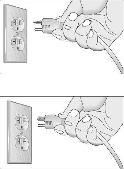
Use the power adapter provided with the equipment. Plug
the power adapter into an appropriate, grounded power
outlet as marked on the equipment.