685370
27
Verklein
Vergroot
Pagina terug
1/56
Pagina verder
PTRV- 17.5K
PTRV- 20K
PTRV-17.5KT
PTRV-20KT
Operator
&
Installation
Manual
Power Technology Southeast, Inc.
634 State Road #44 Leesburg, FL 34748-8103
(352) 365-2777 Fax (352) 787-5545
3/2007
MANPTRV20
FORWARD
You are now the proud owner of a Power Technology Generator powered by a Kubota engine.
This engine is a product of Kubota’s quality engineering and manufacturing. The engine is made
with fine materials and manufactured under the strictest quality control standards and will assure you long
satisfactory service. To obtain the best use of your engine, please read this manual carefully. It will help you
become familiar with the operation of the engine and contains many helpful hints regarding engine
maintenance. Continuing improvements and advancements in product design may have caused changes to
your engine, which are not included in this manual.
Please contact Power Technology’s Customer Service Department for latest information on your Kubota
engine or for the number of your local Kubota dealer.
TO OUR CUSTOMERS
Thank you for your purchase of a Power Technology Generator. The information contained in this
manual applies to PTRV-17.5K & KT, PTRV-20K & KT generators. In the event you experience a problem
with your generator please contact the sales dealer, one of our authorized service centers or Power
Technology’s Customer Service Department directly at 1-800-760-0027 from 8:00 a.m. to 5:00 p.m. EST.
Please have the generator model and serial numbers available when you call. This will help expedite service
and parts to you. Parts may be obtained directly through Power Technology and shipped the same day if
ordered by 3:00 p.m. EST. If required, a Major Service Manual may be ordered through Power
Technology’s Customer Service Department.
Generator Model Number____________________________________________
Generator Serial Number_____________________________________________
POWER TECHNOLOGY SOUTHEAST, INC.
634 STATE RD. 44
LEESBURG, FL. 34748-8103
(352) 365-2777
FAX (352) 787-5545
www.PowerTech-Gen.com
Limited Warranty on Power Tech Generators
Power Technology Southeast, Inc. warrants to you, the original purchaser, that each product of our manufacture is free from defects in materials, and workmanship. That
each generator will deliver its rated output as indicated on The Power Technology Nameplate, if properly installed, serviced, and operated under normal conditions in
accordance with Power Technology’s instructions.
THE WARRANTY COVERAGE TERMS:
2 years from date of purchase, or 3000 hours whichever comes first, or 36 months from the date of manufacture. Parts, and labor, including diagnostic labor, removal, and
reinstallation are covered for the first 12 months from date in service or 1000 hours whichever comes first.
Parts and labor are covered only on the following generator and engine parts for 2 years or 3000 hours whichever comes first. Generator Parts: Main Rotor and Main
Stator. Engine Parts: Cylinder Block, cylinder head, crankshaft, camshaft, cylinder head gears, connecting rods, flywheel and flywheel housing, intake and exhaust manifold
(only if flexible connection is used).
3) Stand-by Units are covered for a period of 1 year from date of installation, or 1000 hours, or 24 months from the date of manufacture whichever comes first.
4) Replacement Parts are warranted: 30 days. (Excluding the following: voltage regulators, fuses, controllers, capacitors, brushes, and switches)
________________________________________________________________________________________________________________________________
WHAT POWER TECHNOLOGY WILL DO:
Power Tech will at our option, repair or replace any part covered by this warranty which becomes defective, malfunctions or otherwise fails to conform to this warranty
under normal use and service during the term of this warranty.
WHAT YOU MUST DO TO OBTAIN WARRANTY SERVICE:
In order to obtain warranty repairs you must deliver the product, together with proof of purchase to an authorized Power Tech service facility. In the case of repairs
pertaining to the engine only, you must use an authorized dealer or distributor of that make of engine, to be covered under their warranty. Engines used in the manufacture
of Power Tech products are warranted solely by the engine manufacturer.
PRIOR APPROVAL IS REQUIRED FOR ANY WARRANTY SERVICE
Failure to obtain authorization prior to the repair being performed will result in the claim being denied.
All claims must be submitted within 30 days of the repair. Along with the following: a copy of the original repair order, Power Tech authorization number, Power Tech
serial number, and operation hours shown on the genset mounted hour meter.
THIS WARRANTY DOES NOT COVER THE FOLLOWING:
A. Normal wear items, including but not limited to: turbo-chargers, fuel injector (s), starter, alternator, and electronic components, as well as normal engine and/or generator
wear. A1. Travel time and fuel charges to and from the repair facility or travel time and fuel charges for mobile service. (Except stationary units with a maximum of 2-hours
travel time.) B. Defects, malfunctions or failure resulting from accidents, abuse, misuse, improper servicing, improper installation, improper storage, and lack of
performance of required maintenance service. C. Products which have been subjected to alteration, modification, neglect or unauthorized repairs. D. Troubleshooting,
routine service, tune-ups, replacement of filters, belts, coolant, lubricants, hoses, clamps, exhaust system components, fuel system components, gaskets and/or seals. E.
Electrical items damaged by welding or jump-starting. F. Damage caused by water ingestion or electrolysis. G. Damage caused by ingestion of substances other than clean
filtered air, fuel, or intake water. H. Damage caused by faulty repairs performed by a repair facility not authorized in writing by Power Tech. I. Damage caused by operation
with improper fuel or at speeds, loads, conditions, modifications, or installation contrary to published specifications or recommendations. J. Original installation charges and
startup costs. K. Removal and re-installation charges of more than 1-hour labor for outside units, 2-hours for compartment mounted units, and 3-hours for below deck
marine units. Customer is responsible for additional labor/charges due to difficult access, removal or installation. L. Starting batteries and labor or charges related to battery
service. M. Loss of revenue or the rental of equipment due to down time. N. Generator repairs made within the warranty period other than by an authorized Power Tech
service dealer without prior written approval from Power Tech warranty department. O. Damage caused by negligent maintenance such as but not limited to: Failure to
provide the specified type and quantity of lubricating oil, cooling air flow, and proper coolant mixture and level. Failure to provide adequate air intake/or maintenance of the
air intake system. Failure to provide scheduled maintenance as prescribed in supplied manuals. P. Engine fluids such as fuel, oil or coolant/antifreeze. Q. Shop supplies such
as adhesives, cleaning agents, rags, paint, or other miscellaneous supplies. R. Use of other than factory supplied or approved repair parts or procedures. Replacement of a
failed Power Tech component with a non-Power Tech component voids the Power Tech warranty on that component and any and all failures related to that component. S.
Fuel injection pumps repaired by anyone other than the factory authorized dealer or distributor of that engine. T. Expenses incurred investigating performance complaints
unless defective Power Tech materials or workmanship are discovered. U. Generator sets used in rental applications. V. Cleaning, service, or repair of generator sets the
have not been kept free of dirt, debris, or other items that prevent the unit from being able to operate properly. W. Any generator set not application approved. X. Loss of
excitation due to prolonged storage. Y. Any damage attributed to low battery monitoring or automatic generator starting systems. Z. Optional accessories are warranted
solely by the manufacturer of that item including but not limited to the following item: Block heaters, oil pan heaters, electric cooling fans, air-bag isolators, compartment
heaters, fuel tanks, trailers, battery chargers, battery monitors.
To obtain warranty service:
For your nearest Power Tech authorized service center, on the World Wide Web at: http://www.powertech-gen.com/parts_service.php
Call 1-352-365-2777 or write to Power Tech Warranty Department, P.O. Box 490133 Leesburg, FL 34749 USA.
Power Tech must be notified in writing within five (5) business days of any product failure.
General Conditions:
This Warranty is the sole property of the original owner /user.
A transfer of ownership shall terminate this Warranty.
This Warranty is only valid within the contiguous United States and Canada.
Warranty coverage is available outside the U.S. and Canada; please speak to a factory representative for those details.
This Warranty does not cover any products or parts not purchased from Power Technology.
Power Technology reserves the right to make design improvements and model changes without any obligation to change units or parts previously manufactured.
Warranty registration card must be completed and mailed to Power Tech at the above address to validate the Warranty.
This is the only express warranty on Power Tech products
No person, agent, or dealer is authorized to give any Warranties on behalf of Power Technology Southeast, Inc., and not to assume for Power Technology Southeast,
Inc. any other liability in connection with any of its products unless made in writing and signed by an officer of Power Technology Southeast, Inc.
LIMITATIONS ON OUR RESPONSIBILITY WITH RESPECT TO PRODUCTS PURCHASED AND USED FOR PERSONAL, FAMILY OR HOUSEHOLD USE:
Our responsibility is to repair or replace defective parts as stated above. We will not be responsible for any other expenses, losses or inconvenience which you may
Sustain as a result of the purchase, use, malfunction or defective condition of our products. ANY IMPLIED WARRANTIES, INCLUDING WARRANTIES OF
MERCHANTABILITY OR FITNESS FOR A PARTICULAR PURPOSE SHALL BE LIMITED IN DURATION TO THE PERIOD SET FORTH ABOVE.
Some states do not allow limitations on how long an implied Warranty lasts or the exclusion or limitation of incidental or consequential damages, so the above
Limitations or exclusions may not apply to you. This Warranty gives you specific legal rights and you may have other rights which vary from state to state.
This Warranty is in lieu of all other Warranties, expressed or implied and of any other obligations or liability on our part.
Our responsibility for any and all losses and IN NO EVENT WILL WE BE LIABLE FOR LOSS OF USE, LOSS OF PROFITS, INCONVIENCE, COMMERCIAL LOSS
OR OTHER INCIDENTIAL OR CONSEQUENTIAL DAMAGES WHATSOEVER.
Power Technology S.E., Inc.
P.O. Box 490133 Leesburg, FL 34749 USA.
Z code 04/20/2010
TABLE of CONTENTS
SECTION 1: SAFETY
SAFE OPERATION 1-4
SECTION 2: ENGINE
PRE-OPERATION CHECK 1
OPERATING THE ENGINE 2
ENGINE SPECIFICATIONS 3
ENGINE MAINTENANCE SERVICE SCHEDULE
4
ENGINE OIL MAINTENANCE
5
ENGINE COOLANT MAINTENANCE 6
OPERATING HOURS AND SERVICE LOG 7
ENGINE TROUBLESHOOTING GUIDES 8-10
SECTION 3: “GENERATOR END
PRINCIPLES OF OPERATION 1-2
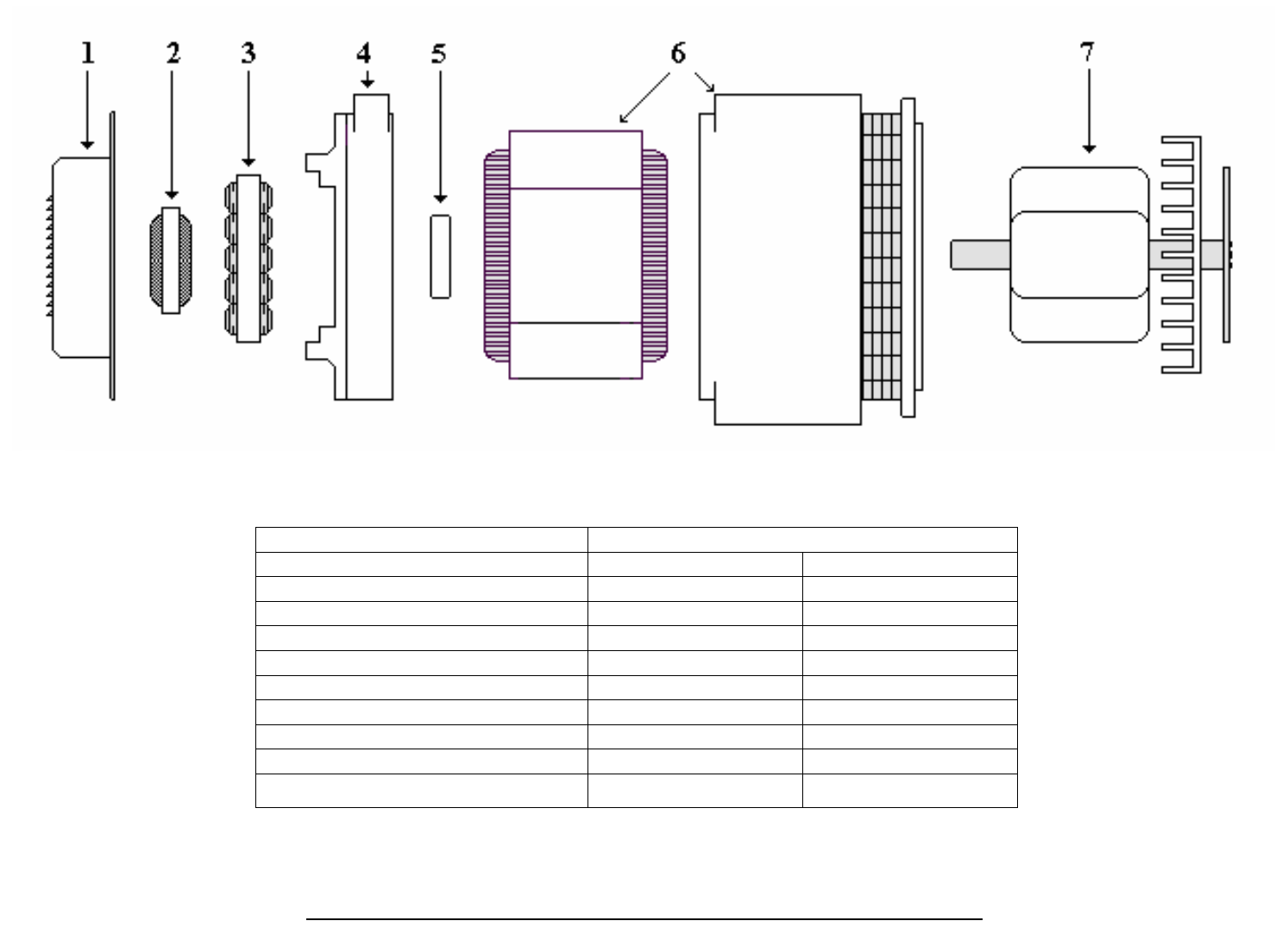
“M” SERIES EXCITER TYPE GENERATOR ASSEMBLY __ 3
GENERATOR END TROUBLESHOOTING GUIDES 4-6
WIRING SCHEMATICS and RESISTANCE CHARTS_____________________ 7-8
SECTION 4: INSTALLATION
SAFETY PRECAUTIONS 1-2
GENERATOR INSTALLATION in RECREATIONAL VEHICLES
3-9
SYSTEMS CONNECTION 10-13
ELECTRICAL CONNECTIONS
14-19
12V DC ENGINE CONTROL WIRING SCHEMATIC
SECTION 5: “POWER CONTROL MODULE”
POWER CONTROL MODULE (PCM) and DISPLAY (PCMD) _____________ 1-3
TROUBLESHOOTING GUIDES ______________________________________ 4-10
12 VOLT DC POWER CONTROL MODULE WIRING SCHEMATIC _______ 11
SECTION 1
“SAFETY”
SAFE OPERATION
1-4
Observe Safety Instructions
Wear Safety Clothing
Check Before Operating the Engine
Keep Area Around the Engine Clean
Safe Handling of Fuel and Lubricants
Exhaust Gases and Fire Prevention
Escaping Fluids
Cautions Against Burns and Battery Explosion
Keep Hands and Body Away From Rotating Parts
Anti-Freeze and Disposal of Fluids
Conducting Safety Checks and Maintenance
This symbol, the industry’s “Safety Alert Symbol”, is used throughout this manual and
on labels attached the machine itself. It warns of the potential for personal injury. It is
essential that you carefully read the instructions and safety regulations before you attempt
to assemble or use this unit.
WARNING: Indicates a potentially hazardous situation, which
may possibly result in serious injury or possible death.
CAUTION: Indicates a potentially hazardous situation, which
may possibly result in minor injury.
IMPORTANT: Indicates that equipment or property damage may result
if instructions are not followed.
NOTE: Indicates helpful information.
SAFE OPERATION
Cautious operation is your best insurance against an accident. Read and understand this section carefully
before operating the engine. All operators, no matter how knowledgeable they may be, should read this
and other related manuals before operating the engine or any equipment attached to it. It is the owner’s
responsibility to instruct all operators in safe operation. Be sure to observe the following for safe
operation.
OBSERVE SAFETY INSTRUCTIONS
Read, understand and follow this “OPERATORS MANUAL”
and “LABELS ON THE ENGINE” before starting and operating
the engine.
Learn how to operate and work safely. Know your equipment
and its limitations. Always keep the engine in good condition.
Before allowing other people to use your engine, explain how
to operate and have them read this manual before operation.
DO NOT modify the engine. UNAUTHORIZED
MODIFICATIONS to the engine may impair the function
and/or safety and affect engine life.
WEAR SAFETY CLOTHING
DO NOT wear loose, torn or bulky clothing around machinery.
Entanglement in rotating parts, controls or projections may cause
personal injury.
Use additional safety items, e.g. hardhat, eye protection,
gloves, etc., as appropriate or required.
DO NOT operate machinery or equipment while under the
influence of alcohol, medication, or other drugs, or
while fatigued.
DO NOT wear radio or music headphones while operating engine.
CHECK BEFORE OPERATING THE ENGINE
If the engine is malfunctioning DO NOT operate until repairs
are made.
Be sure all guards and shields are in place before operating
the engine. Replace any that are damaged or missing.
Check to see that the area around the engine is clear of foreign
objects before starting.
Always keep the engine at least 3 feet (1 meter) away from
buildings or other facilities.
DO NOT allow children or livestock to approach the machine
while in operation.
DO NOT start the engine by shorting across starter terminals.
1
KEEP AREA AROUND THE ENGINE CLEAN
Be sure to stop the engine before cleaning.
Keep the engine clean and free of accumulated dirt, grease and trash.
DO NOT stop the engine without idling; Temperatures around
the engine rises suddenly. Keep the engine idling for about 5
minutes before stopping.
SAFE HANDLING OF FUEL AND LUBRICANTS
Always stop the engine before refueling or lubricating.
DO NOT smoke or allow flames or sparks in your working
area. Fuel is extremely flammable and explosive. Never store
flammable liquids in the engine compartment.
Refuel at a well-ventilated and open place. If fuel or lubricants
spill, clean up immediately and properly dispose of.
DO NOT mix gasoline or alcohol with diesel fuel. The mixture
can cause a fire.
EXHAUST GASES AND FIRE PREVENTION
Engine exhaust fumes can be very harmful if allowed to
accumulate. Be sure to run the engine in a well-ventilated area
where there are no people or livestock near by.
The exhaust gas from the muffler is very hot. To prevent a fire,
do not expose dry grass, oil or any other combustible materials
to exhaust gas. Keep the engine and mufflers clean all the time.
To avoid a fire, be alert for leaks of flammables from hoses and
lines. Be sure to check for leaks from hoses and pipes, such as
fuel and hydraulic by following the maintenance check list.
To avoid a fire, do not short across power cables and wires.
Check to see that all power cables and wires are in good
condition. Keep all power connections clean. Bare wire or
frayed insulation can cause a dangerous electrical shock and
personal injury.
2
CALIFORNIA
Proposition 65 Warning
Diesel Engine Exhaust and some
of it’s constituents are known by the
State of California
to cause
Cancer, Birth Defects and Other
Reproductive harm.
ESCAPING FLUIDS
Relieve all pressure in the air, oil and cooling systems
before any lines, fittings or related items are removed or
disconnected.
Be alert for possible pressure release when disconnecting any device
from a system that is pressurized. DO NOT check for
pressure leaks with your hands. High-pressure oil or fuel can
cause personal injury.
Escaping hydraulic fluid under pressure has sufficient force to
penetrate skin causing serious personal injury.
Fluid escaping from pinholes may be invisible. Use a piece of
cardboard or wood to search for suspected leaks: do not use
hands and body. Use safety goggles or other eye protection
when checking for leaks.
If injured by escaping fluid, see a medical doctor immediately.
This fluid can produce gangrene or severe allergic reaction.
CAUTIONS AGAINST BURNS AND BATTERY EXPLOSION
To avoid burns, be alert for hot components during operation and
just after the engine has been shut off. Such as the muffler, muffler
cover, radiator, piping, engine body, coolants, engine oil, etc.
DO NOT remove the radiator cap while the engine is running or
immediately after stopping. Wait approximately ten minutes for the
radiator to cool before removing the cap.
Be sure the radiator drain valve / petcock and hose clamps are
tighten. Check radiator pressure cap and oil fill cap before operating
the engine.
The battery presents an explosive hazard. When the battery is
being activated, hydrogen and oxygen gases are extremely explosive.
Keep sparks and open flames away from the battery, especially
during charging. DO NOT strike a match near the battery.
DO NOT check a batteries charge by placing a metal object across
the terminals. Use a voltmeter or hydrometer.
DO NOT charge a battery if frozen, it may possibly explode. Frozen
batteries must be warm up to at least 61°F (16°C) before charging.
KEEP HANDS AND BODY AWAY FROM ROTATING PARTS
Keep your hands and body away from all rotating parts, such
as cooling fan, v-belts, pulleys and flywheel. Contact with these
rotating parts can cause serious personal injury.
Be sure to stop the engine before adjusting belt tension or checking
the cooling fan.
DO NOT run the engine without safety guards installed. Be sure the
safety guards are properly aligned and securely fastened before operating
the engine.
3
ANTI-FREEZE AND DISPOSAL OF FLUIDS
Anti-freeze contains toxic chemicals. Wear rubber gloves when
handling anti-freeze. In case of contact with skin, wash immediately
to avoid personal injury.
DO NOT mix different types of Anti-freeze. The mixture can
produce a chemical reaction resulting in the formation of harmful
substances. Only use anti-freeze that is recommended and approved
by Caterpillar.
Be mindful of the environment. Before draining any fluids, be
prepared to dispose of them in a manner consistent with
environmental protection regulations in your location.
When draining fluids from the engine, use appropriate containers to
hold the different fluids, do not mix fuel, oil or coolant together.
Dispose of spent filter cartridges and batteries properly.
DO NOT pollute the soil, or any water source. Never pour fluids
down a drain.
CONDUCTING SAFETY CHECKS AND MAINTENANCE
When performing safety checks or engine service, be sure the engine is level
and well supported. Use approved stands designed for this type of service.
DO NOT service an engine that is only supported by a lift jack or hoist.
Detach the battery from the engine before conducting service. Put a
“DO NOT OPERATE!” tag in the key switch to avoid accidental starting.
To avoid sparks from an accidental short circuit always disconnect
the 12V DC power at the battery.
Be sure to stop the engine and remove the key when conducting
daily and periodic maintenance, servicing and cleaning.
Check or conduct maintenance after the engine, radiator, muffler, or
muffler cover has cooled off completely.
Always use the appropriate tools and jig-fixture when performing any
service work. Be sure to understand and follow the instructions included
with these tools.
Use ONLY correct engine barring techniques for manually rotating
the engine. DO NOT attempt to rotate the engine by pulling or prying
on the cooling fan and V-belt. Serious personal injury or damage to the
cooling fan may occur.
Replace fuel hoses and hose clamps every 2 years or earlier whether they
are damaged or not. They are made of rubber and are aged gradually.
When service is performed with two or more people present, take care
to perform all work safely. Be aware of their location especially when
starting the engine.
Keep a first aid kit and fire extinguisher handy at all times.
4
SECTION 2
“ENGINE”
PRE-OPERATION CHECK 1
Engine Break-in Period
Daily Check
OPERATING THE ENGINE 2
Engine Starting Controls
Check Engine After Starting
Stopping the Engine
ENGINE SPECIFICATIONS 3
Kubota Model V-2203
Service Parts
ENGINE MAINTENANCE SERVICE SCHEDULE 4
ENGINE OIL MAINTENANCE 5
Checking Engine Oil Level
Lubricating Oil Specifications
Engine Refill Capacities
Lubricating Oil Viscosity Recommendations
ENGINE COOLANT MAINTENANCE 6
Coolant Recommendations
Ethylene Glycol / Propylene Glycol
Checking Radiator Coolant Level
Coolant Service Life
Checking Reservoir Tank Coolant Level
Cleaning Radiator Core
OPERATING HOURS AND SERVICE LOG 7
ENGINE TROUBLESHOOTING GUIDES
8-10
Engine Starts but Won’t Run
Engine Runs Rough or Slow
Engine Will Not Start
PRE-OPERATION CHECK
ENGINE BREAK-IN PERIOD
During the engine break-in period, observe the following recommendations:
1. Change the engine oil and oil filter cartridge after the first 50 hours of operation.
(See “ENGINE OIL” in ENGINE MAINTENANCE SERVICE SCHEDULE).
2. In ambient temperature above 32°F (0°C) approximately 3-5 minutes without a load is sufficient
for engine warm up. Allow additional warm up time when temperatures are below 32°F (0°C)
before placing an operating load on the engine.
DAILY CHECK
To prevent future engine problems from occurring, it is important to know and keep track of the engines
condition. Below are items to be Inspected and Checked on a daily basis.
CAUTION:
To avoid personal injury:
Be sure all safety shields and guards are attached to the engine when operating.
To prevent a fire hazard, keep foreign materials, fuel and oil away from the battery, wiring, muffler
and engine. Check and clear them daily. Be aware of the muffler and exhaust gas heat underneath the
engine compartment, this heat may ignite grass or other flammable materials.
Follow all safety precautions as outlined in the “SAFE OPERATION” section.
1. For accurate readings the engine should be on level ground when checking engine fluids.
2. Check fluids before starting the engine. (Cold Engine)
Lubrication System: Check Engine oil level
Check for Engine oil leaks
Cooling System: Check coolant level and condition
Check for coolant leaks
Check for proper installation of the radiator cap
Fuel System: Check for sufficient quantity of fuel
Check for fuel leaks
3. Check engine after starting. (Warm Engine)
Proper Operation: Check for easy engine start
Check for fluid leaks
Check for abnormal engine noises
Check for abnormal exhaust gas
1
OPERATING THE ENGINE
ENGINE STARTING CONTROLS
1) Generator Main Switch must be in the ON position.
2) Hold Start/Stop Switch for 1 second and release.
3) Glow Plugs will preheat for 8 seconds. LED flashes slowly.
4) Preheating will cease during engine cranking cycle. LED continues flashing.
5) Engine begins an 8 seconds crank cycle, After 4 seconds of cranking the PT-ECU-63 will check
for an AC signal from the generator. If an AC signal is verified the engine will start and the LED
will remain ON during the normal run operation. If the AC signal is not verified the PT-ECU-63
will terminate the cranking cycle and LED will flash a fault code.
6) Starter disengages immediately after engine run is verified.
7) PT-ECU-63 deactivates the Low Oil Pressure and High Water Temperature Switches for 6
seconds, this will assure oil pressure build-up time. If oil pressure does not build-up the engine will
immediately shut down and go into a fault mode. Likewise for a high temperature situation.
8) If engine will not start on the first attempt the PT-ECU-63 will initiate the start cycle 2 more times
before going into a fault mode. Glow Plugs will preheat for 8 seconds per attempt. Engine will
crank for 8 seconds per attempt.
9) To shut down the engine under normal operations, hold the Start/Stop Switch for 1 second and
release.
10) If a fault occurs turn Generator Main Switch OFF and then ON to reset PT-ECU-63.
CHECKING ENGINE AFTER STARTING
1) Allow the engine to warm up 3 to 5 minutes before applying a load. In colder climates allow a few
extra minutes longer.
2) Perform a visual inspection of all areas of the engine and generator.
3) Listen for any abnormal noises.
4) Check for any abnormal exhaust gases.
STOPPING THE ENGINE
It is recommended to disconnect or reduce the power load from the generator before shutting down the
engine. Then follow the steps outlined above for normal shut down.
NOTE: The PT-ECU-63 is designed to operate on 12V DC power. In a low battery situation the
PT-ECU-63 may not initiate the normal cranking cycle. To start the generator you can press and
hold the Start/Stop Switch for approximately 10 seconds or until the engine starts. Once the
engine starts the PT-ECU-63 will resume normal operations. If this situation re-occurs, charge or
replace the battery.
IMPORTANT: Damage to the Starter Motor, Starter Solenoid, Run Solenoid or any generator component
due to excessive or prolonged starting attempts attributed to an external Low Battery Control Monitoring
or Auto-Start System will not be covered by the Power Technology Southeast, Inc. Limited Warranty.
2
ENGINE SPECIFICATIONS
MODEL V-2203 V-2003-T
SERVICE PARTS
Power Technology Part #
Filters:
Oil ----------------------------------------------------------------------------------- 01FO091
Fuel ---------------------------------------------------------------------------------- 08FF081
Air with Metal Canister----------------------------------------------------------- 04FA080
Air with Plastic Canister---------------------------------------------------------- 04FA2E1
Belts:
With Alternator ------------------------------------------------------------------- 03BF0203
With Idler Pulley ----------------------------------------------------------------- 03BF9447
3
Air Induction Naturally Aspirated Turbocharged
Continuous Output 32.5 HP @ 1800 rpm 36.3 HP @ 1800 rpm
Cubic Capacity 134.07 in³ (2.19L) 121.99 in³ (1.99L)
Bore and Stroke 3.43 x 3.64 3.27x3.64
(87x92.4mm) (83x92.4mm)
Cylinder Arrangement 4 In-Line 4 In-Line
Firing Order 1-3-4-2 1-3-4-2
Compression Ratio 23:1 22:1
Engine Oil Capacity 8.5 qts. (8.04L) 8.5 qts. (8.04L)
Fuel and Type Diesel 4 Cycle Diesel 4 Cycle
Minimum Fuel Consumption See Specification Chart See Specification Chart
Engine Maintenance Service Schedule
Maintenance
Service Item
*See
Note
Daily
Min.
Every
25 Hours
Every 100
Hours
Every 250
Hours
Every 500
Hours
Every
1000
Hours
Remarks
Engine Oil Level
Deterioration &
Leakage
X
Engine Oil
Change
*
X
Or Once
a Year
Oil Filter
Change
X
Or Once
a Year
Coolant Level
X
Coolant Leakage
X
Coolant Change
X Or Once a Year
Fuel Level
X
As Necessary
Fuel Leakage
X
Fuel Filter Re-
placement
X Or Once a Year
Air Filter Re-
placement
**
X Or Once a Year
Damaged Worn
Or Loose Belts
X
Or Every Two
Years
Replace Fuel
Hoses
X
Or Every Two
Years
Check Radiator
Hoses & Clamps
X
Once a Year
Abnormal Engine
Noise
X
Abnormal
Generator Noise
X
Muffler Condition
X
Exhaust Gas
Condition
X
* Engine oil and filter must be changed after the first 50 hours of operation. Then every 100
hours or once a year whichever comes first.
** Air filter replacement interval will vary depending on operating conditions. Adverse conditions may
require frequent service.
NOTE: Under normal operation items such as Belts, Hoses and Filters are not covered by Power
Technology Southeast, Inc. Limited Warranty.
4
ENGINE OIL MAINTENANCE
Ambient Temperature Oil Viscosity
Above 25°C (77°F)
SAE 10W-30
SAE 30 or
SAE 10W-40
0 to 25°C (32° to 77°F)
SAE 10W-30
SAE 20 or
SAE10W-40
Below 0°C (32°F)
SAE 10W-30
SAE 10W or
SAE 10W-40
5
CHECKING ENGINE OIL LEVEL
( Y ) “ADD” mark. ( X ) “FULL” mark.
1. Maintain the engine oil level between “ADD”
mark and “FULL” mark on oil level gauge.
Do not fill crankcase above “FULL” mark.
2. Remove the oil filler cap and add oil, if
necessary. Clean the oil filler cap. Install the oil
filler cap.
The refill capacities for the engine crankcase
Reflect the approximate capacity of the
crankcase or sump plus a standard oil filter.
Auxiliary oil filter systems will require
additional oil.
KUBOTA V-2203 & V-2003-T ENGINE
REFILL CAPACITIES
Crankcase Oil Sump 8.5 Qts. (8.04L)
and Filter
LUBRICATING OIL VISCOSITY
RECOMMENDATIONS
The minimum ambient temperature during cold
engine start-up and the maximum ambient
temperature during engine operation determine the
proper SAE viscosity grade of oil.
Refer to the Engine Oil Viscosity Table below
(Minimum Temperature) in order to determine the
required oil viscosity for starting an engine in cold
conditions.
Refer to the Engine Oil Viscosity Table below
(Maximum Temperature) in order to select the oil
viscosity for engine operation at the highest ambient
temperature that is anticipated.
LUBRICATING OIL
SPECIFICATION
Use only good quality
lubricating oil, which meets
or exceeds of the following
Specification
API-CD
or
Higher
ENGINE COOLANT MAINTENANCE
6
COOLANT SERVICE LIFE
Coolant Type Service Life
Commercial Heavy-Duty
Coolant/Antifreeze that 3000 Service Hours
Meets “ASTM D5345” or Two Years
Commercial Heavy-Duty
Coolant/Antifreeze that 3000 Service Hours
Meets “ASTM D4985” or One Year
NOTE: Do not use a commercial
coolant/antifreeze that only meets the ASTM
D3306 or D4656 specification. This type of
coolant/antifreeze is made for light duty
automotive applications.
CHECKING RESERVOIR TANK
COOLANT LEVEL
(At a Minimum of 25 Hours of Operation)
Ensure that the coolant level of the radiator
reservoir tank is between the upper limit (FULL)
and the lower limit (LOW) on the side of the
reservoir tank.
CLEANING RADIATOR CORE
Visually inspect the core for any obstructions such
as dirt or debris. Use running water to clean
particles from between fins.
IMPORTANT: Never use hard objects to clean
radiator core, damage to core could result.
COOLANT RECOMMENDATIONS
For optimum performance, Power Technology
recommends a 1:1 mixture of water / glycol.
NOTE: Use a mixture that will provide
protection against the lowest ambient
temperature.
NOTE: 100 percent pure glycol will freeze at a
temperature of –23°C (-9°F).
Most conventional heavy-duty coolant /
antifreezes use Ethylene Glycol. Propylene
Glycol may also be used in a 1:1 mixture with
water. Ethylene and Propylene Glycol provide
similar protection against freezing and boiling.
See the tables below.
ETHYLENE GLYCOL
Freeze Boil
Concentration Protection Protection
50 Percent -36°C (-33°F) 106°C (223°F)
60 Percent -51°C (-60°F) 111°C (232°F)
PROPYLENE GLYCOL
Freeze Boil
Concentration Protection Protection
50 Percent -29°C (-20°F) 106°C (223°F)
NOTE: Do not use Propylene Glycol in
concentrations that exceed 50 percent glycol
because of Propylene Glycol’s reduced heat
transfer capability. Use Ethylene Glycol in
conditions that require additional protection
against boiling or freezing.
CHECKING RADIATOR COOLANT LEVEL
Remove the radiator cap after the engine has
completely cooled and check to see that
coolant reaches the supply port.
1. Fill to the bottom of the fill neck and
check after every 25 hours of operation.
OPERATING HOURS and SERVICE LOG
THIS SERVICE LOG IS PROVIDED TO HELP YOU KEEP AN ACCUMULATIVE RECORD OF OPERATION HOURS ON YOUR GENERATOR
SET AND THE DATES REQUIRED SERVICES WERE PERFORMED. ENTER TIME TO THE NEAREST HOUR.
OPERATING HOURS SERVICE RECORD
DATE HRs. RUN CUMLATIVE DATE SERVICES
7
Engine Runs OK
Has Power NO Power
Has Power NO Power
Engine runs OK NO Power
8
ENGINE STARTS
BUT WON’T RUN
Unplug Remote
Start-Stop from
Control Box
Problem with
Remote Connection.
Contact
Equipment Manufacture
r
Jump across
Oil Pressure Switch
with Jumper Wire
(2 pole)
Check Power
to Hold Circuit
of Run Solenoi
d
Check
Oil Pressure
With Gauge
Replace
Oil Pressure Switch
Defective Solenoid
REPLACE
Plug Remote
Back IN
Remote OK
Problem with Remote
Check
Safety Shutdown
System
Remove Wire From
Water Temperature Switch
Replace Water
Temperature
Switch
Check Shutdown
Relay
Check Wirin
g
Oil Pressure Switch
Single Pole
Disconnect Wire to Test
If “OK”
Replace
Switch
BLUE
GRAY/WHITE
BLACK
9
ENGINE RUNS
ROUGH or SLOW
NO Visible Exhaust Smoke Excessive Exhaust Smoke
Insufficient
Fuel to Engine
Check
Fuel Level
Replace
Fuel Filter
Air IN
Fuel
System
Check
Fuel
PUMP
Excessive Oil Level
Dirty Air Filter
Engine Overheated
Engine Over Loaded
Clogged Muffler
Over Fueling Injector
HIGH ALTITUDE
Engine Cold
Incomplete
Combustion
Over-fueling
Injector
Glow Plug
Not Activating
Check
With 12 volt DC
Test Light
Check
Safety Shutdowns
And
Fuel Solenoid
YES NO
10
ENGINE WILL NOT
START
Engine Cranks
Engine Does NOT
Crank
Engine
Cranks SLOW
NO
Exhaust
Smoke
Smoke
From
Exhaust
Check Fuel
Solenoid
NO
Power While
Cranking
Defective
Solenoid
No Power
From
Starter Terminal
Check
Fuel
Supply
Check
Fuel
Pump
Air IN
Fuel
System
Check
Glow
Plugs
Check
Glow Plug
Relay
Main Switch Battery
Dead
Turn
Switch
“ON”
Start
Switch
Starter
Relay
Starter
Motor
Oil Viscosity
TOO HEAVY
LOW
Battery
Voltage
Check
Terminal
Ends
Check Spark
Arrestor
Muffler for
Clogging
SECTION 3
“GENERATOR END”
PRINCIPLES OF OPERATION
1-2
Rotating Field Assembly (Rotor)
Core Assembly
Field Coil
Voltage Connection
Electronic Voltage Regulation
Exciter Field Coil Voltage Source
Balance
Bearing
Stator Assembly
“M” SERIES EXCITER TYPE GENERATOR ASEMBLY 3
GENERATOR END TROUBLESHOOTING GUIDES 4-6
Zero or Low Voltage
Voltage Test
12-Volt Battery Test
Overload Condition
WIRING SCHEMATICS and RESISTANCE CHARTS___________________________ 7-8
120 Volt Connection “M” Series Exciter Type
120 / 240 Volt Connection “M” Series Exciter Type
GENERATOR ASSEMBLY INFORMATION
EXCITER TYPE GENERATOR
The exciter pole pieces contain residual magnetism, which sets up lines of force across the air
gap to the exciter armature. When the exciter begins to rotate a voltage is induced and current flow is
initiated in the exciter armature AC windings. This voltage is fed to the rotating rectifier assembly,
rectified and fed to the alternator field, which sets up lines of force across the air gap to the alternator
stator windings and to the output circuit.
A static voltage regulator is connected to the generator output. The regulator will rectify part of
the output voltage to provide a DC voltage to the exciter field coils. This will increase the density of the
lines of force in the exciter, increasing the voltage induced into the exciter armature windings, and
therefore, to the rotating rectifiers. The rotating rectifier output will be increased which will increase the
alternator field strength and generator output will build up its rated voltage. Adjustment of the generator
output to the rated voltage level is accomplished by controlling the current fed to the exciter field coils.
Regulation is automatic with the static type voltage regulator. An additional voltage adjustment range is
provided if desired by turning the Voltage Adjust Rheostat.
ELECTRONIC VOLTAGE REGULATION
Electronic Voltage Regulator (EVR) also referred to, as an Automatic Voltage Regulator (AVR)
is a very reliable device, which uses solid-state electronics to maintain voltage accuracy at ±2% of the
regulated voltage. The Voltage Regulator is designed to automatically regulate and maintain the
generated AC voltage through out the load range, that is from no load to full load.
VOLTAGE CONNECTION
The generator may be connected at the terminal board to deliver 120/240 volts to a 3 wire
grounded neutral system, or 120-volts only to a 2 wire distribution system. If any equipment requires
240-volts, then the 120/240-volt connection must be used. If all equipment requires 120-volts then
the 120-volt connection is preferred, even if two lines leave the same switch box. The two lines at
the inputs to the switch box are both connected to the un-grounded 120-volt lines from the generator.
The 120-volt connection enables the Electronic Voltage Regulator (EVR) to hold the voltage very
close to the 115 or 120 volts, as initially adjusted, regardless of the power distribution amount the
different distribution lines. The 120-volt connection is recommended if the entire electrical load
requires only 115 or 120 volts.
Although the 120/240-volt connection may also be used when all loads requires only 110 volts, it
should be pointed out that this connection, the 240-volts, is regulated and the lightly loaded phase, or
line, will deliver a high line to neutral voltage and the heavily loaded phase will deliver a low line to
neutral voltage. The heavily loaded line may have such a low voltage that air conditioning will have
more difficulty in starting, and long starting lines may overload generator and trip circuit breakers
EXCITER FIELD COIL VOLTAGE SOURCE
Field coil DC voltage is obtained by rectifying the voltage from the phase to neutral line of the
generator output, or either appropriate terminal to provide the needed voltage reference.
The rectifier bridge is an internal part of the static regulator. The static regulator senses a change
in the generator output and automatically regulates current flow in the exciter field coil circuit to
increase or decrease the exciter field strength. An adjustable rheostat sized to be compatible with
the regulator is used to provide adjustment of the regulator sensing circuit.
1
ROTATING FIELD ASSEMBLY (ROTOR)
The rotating field assembly consists basically of four members: 1) the shaft assembly, 2) the
core assembly, 3) the field coil damper windings, and 4) balance lugs to provide a high degree of static
and dynamic balance.
CORE ASSEMBLY
The core assembly consists of a quantity of thin steel plates compressed and fastened together to
form a single laminated assembly. The field windings are wound around this assembly.
FIELD COIL
Field coils of heavily insulated wire are “wet” wound directly onto the poles. Field coil leads are
brought out to the rectifier assembly for connection to the source of DC excitation voltage.
BALANCE
The rotor assembly is precision balanced to a high degree of static and dynamic balance.
Although the balance will remain dynamically stable at speeds in excess of the design frequencies, the
prime mover should be adequately governed to prevent excessive over speed. High centrifugal forces
created by excessive over speed may damage the rotor windings and field coils.
BEARING
The generator rotor assembly is suspended on a shielded factory lubricated ball bearing. A visual
inspection of the bearing is recommended at typical service intervals. If signs of abnormal wear
or leakage are observed, the bearing should be replaced. Never use liquids of any kind to clean the
generator end and bearing.
STATOR ASSEMBLY
The stator assembly consists of laminations of steel mounted in a rolled steel frame. Random
wound stator coils are fitted into the insulated slots.
2
**NOTE: Item #6 MAIN STATOR ASSEMBLY is a one-piece unit. The Stator cannot be separated from the Generator’s outer housing.
DESCRIPTION PART NUMBER
17.5KW 20KW
1. END COVER NS-GENCAN NS-GENCAN
2. EXCITER ROTOR 02RTR1520EXC 02RTR1520EXC
3. EXCITER STATOR 02STA1520EXCG 02STA1520EXCG
4. REAR HOUSING BRACKET 02HB175 02HB15TCGE
5. ROTOR BEARING 02BRG207 02BRG207
6. MAIN STATOR ASSEMBLY** 02STMN175 02STMN20
7. MAIN ROTOR ASSEMBLY 02RTRMN175 02RTRMN20
GENERATOR ASSEMBLY 02GEN175TCGE 02GEN20TCGE
VOLTAGE REGULATOR 06REG634AVC 06REG634AVC
“M” SERIES EXCITER TYPE GENERATOR ASSEMBLY
3
BAD OK ON OFF
OK
BAD
OK
4
ZERO OR LOW
VOLTAGE
Check Gen Fuse
Check Main
Breaker is “ON”
Replace
Fuse
Turn “ON”
Breaker
Main Coil
Output to
Breaker
OK
BAD
Check Ohm’s on
Exciter Leads
12 V Battery Test
Replace Exciter
Wiring To
Panel
Defective
Breaker
Replace
Voltage Regulator
5
VOLTAGE TEST
Zero
or
Low Voltage
High
Voltage
Overload
Output
Voltage OK
Replace
AVR
Check Load Distribution
One Voltage Line
may be
Higher than the other
Check AMP
Draw
From equipment
Check
Main Breaker
On GenSet
Check
Gen End
12 VOLT
BATTERY TEST
One Coil
Low Voltage
Both Coils
Low Voltage
Sensing Voltage
Low or None
Replace
AVR
Check
Connections
Check Engine
RPM 1800
Replace Stator
Replace
Stator
Replace
Stator
BAD OK
BAD OK
6
OVERLOAD
CONDITION
Disconnect
AVR
Engine Problem
Check
Stator Coil
Resistance
See Engine
Troubleshooting
Replace Stator
Replace AVR
And Test
Check AMP Draw
Check Load Distribution
Conduct
12-Volt Battery Test
27

Hulp nodig? Stel uw vraag in het forum

Spelregels

Misbruik melden

Gebruikershandleiding.com neemt misbruik van zijn services uitermate serieus. U kunt hieronder aangeven waarom deze vraag ongepast is. Wij controleren de vraag en zonodig wordt deze verwijderd.

Product:

Bijvoorbeeld antisemitische inhoud, racistische inhoud, of materiaal dat gewelddadige fysieke handelingen tot gevolg kan hebben.

Bijvoorbeeld een creditcardnummer, een persoonlijk identificatienummer, of een geheim adres. E-mailadressen en volledige namen worden niet als privégegevens beschouwd.

Spelregels forum

Om tot zinvolle vragen te komen hanteren wij de volgende spelregels:

Belangrijk! Als er een antwoord wordt gegeven op uw vraag, dan is het voor de gever van het antwoord nuttig om te weten als u er wel (of niet) mee geholpen bent! Wij vragen u dus ook te reageren op een antwoord.

Belangrijk! Antwoorden worden ook per e-mail naar abonnees gestuurd. Laat uw emailadres achter op deze site, zodat u op de hoogte blijft. U krijgt dan ook andere vragen en antwoorden te zien.

Abonneren

Abonneer u voor het ontvangen van emails voor uw PowerTech PTRV- 17.5K bij:


U ontvangt een email met instructies om u voor één of beide opties in te schrijven.


Ontvang uw handleiding per email

Vul uw emailadres in en ontvang de handleiding van PowerTech PTRV- 17.5K in de taal/talen: Engels als bijlage per email.

De handleiding is 2,37 mb groot.


U ontvangt de handleiding per email binnen enkele minuten. Als u geen email heeft ontvangen, dan heeft u waarschijnlijk een verkeerd emailadres ingevuld of is uw mailbox te vol. Daarnaast kan het zijn dat uw internetprovider een maximum heeft aan de grootte per email. Omdat hier een handleiding wordt meegestuurd, kan het voorkomen dat de email groter is dan toegestaan bij uw provider.

Stel vragen via chat aan uw handleiding

Stel uw vraag over deze PDF

Uw handleiding is per email verstuurd. Controleer uw email

Als u niet binnen een kwartier uw email met handleiding ontvangen heeft, kan het zijn dat u een verkeerd emailadres heeft ingevuld of dat uw emailprovider een maximum grootte per email heeft ingesteld die kleiner is dan de grootte van de handleiding.

Er is een email naar u verstuurd om uw inschrijving definitief te maken.

Controleer uw email en volg de aanwijzingen op om uw inschrijving definitief te maken

U heeft geen emailadres opgegeven

Als u de handleiding per email wilt ontvangen, vul dan een geldig emailadres in.

Uw vraag is op deze pagina toegevoegd

Wilt u een email ontvangen bij een antwoord en/of nieuwe vragen? Vul dan hier uw emailadres in.


Info