685337
4
Verklein
Vergroot
Pagina terug
1/66
Pagina verder
PT20-EC
PT20-ECRR
PT25-EC
PT25-ECRR
Operators
Manual
Power Technology Southeast, Inc.
634 State Road #44 Leesburg, FL 34748-8103
(352) 365-2777 Fax (352) 787-5545
9/2008
MANPT20EC
FORWARD
You are now the proud owner of a Power Technology Generator powered by a Kubota engine.
This engine is a product of Kubota’s quality engineering and manufacturing. The engine is made
with fine materials and manufactured under the strictest quality control standards and will assure you long
satisfactory service. To obtain the best use of your engine, please read this manual carefully. It will help you
become familiar with the operation of the engine and contains many helpful hints regarding engine
maintenance. Continuing improvements and advancements in product design may have caused changes to
your engine, which are not included in this manual.
Please contact Power Technology’s Customer Service Department for latest information on your Kubota
engine or for the number of your local Kubota dealer.
TO OUR CUSTOMERS
Thank you for your purchase of a Power Technology Generator. The information contained in this
manual applies to PT20-EC, PT20-ECRR, PT25-EC, and PT25-ECRR generators. In the event you
experience a problem with your generator please contact the sales dealer, one of our authorized service
centers or Power Technology’s Customer Service Department directly at 1-800-760-0027 from 8:00 a.m. to
5:00 p.m. EST. Please have the generator model and serial numbers available when you call. This will help
expedite service and parts to you. Parts may be obtained directly through Power Technology and shipped
the same day if ordered by 3:00 p.m. EST. If required, a Major Service Manual may be ordered through
Power Technology’s Customer Service Department.
Generator Model Number____________________________________________
Generator Serial Number_____________________________________________
POWER TECHNOLOGY SOUTHEAST, INC.
634 STATE RD. 44
LEESBURG, FL. 34748-8103
(352) 365-2777
FAX (352) 787-5545
www.PowerTech-Gen.com
TABLE of CONTENTS
SECTION 1: SAFETY
SAFE OPERATION 1-4
SECTION 2: ENGINE
PRE-OPERATION CHECK 1
OPERATING THE ENGINE 2-12
ENGINE SPECIFICATIONS 13
ENGINE MAINTENANCE SERVICE SCHEDULE
14
ENGINE OIL MAINTENANCE
15
ENGINE COOLANT MAINTENANCE 16
OPERATING HOURS AND SERVICE LOG 17
SECTION 3: “GENERATOR END
“MAGNAPLUS” SERIES EXCITER TYPE GENERATOR ___________ _ 1-20
GENERATOR EXPLODED VIEW and PARTS NUMBERS_________________ 21
MARATHON SE350 VOLTAGE REGULATOR___________________________ 22-24
WIRING SCHEMATICS and RESISTANCE CHARTS______________________ 25
SECTION 4: INSTALLATION
SAFETY PRECAUTIONS 1-2
GENERATOR INSTALLATION in RECREATIONAL VEHICLES 3-9
SYSTEMS CONNECTION
10-13
ELECTRICAL CONNECTIONS 14-19
SECTION 1
“SAFETY”
SAFE OPERATION
1-4
Observe Safety Instructions
Wear Safety Clothing
Check Before Operating the Engine
Keep Area Around the Engine Clean
Safe Handling of Fuel and Lubricants
Exhaust Gases and Fire Prevention
Escaping Fluids
Cautions Against Burns and Battery Explosion
Keep Hands and Body Away From Rotating Parts
Anti-Freeze and Disposal of Fluids
Conducting Safety Checks and Maintenance
This symbol, the industry’s “Safety Alert Symbol”, is used throughout this manual and
on labels attached the machine itself. It warns of the potential for personal injury. It is
essential that you carefully read the instructions and safety regulations before you attempt
to assemble or use this unit.
WARNING: Indicates a potentially hazardous situation, which
may possibly result in serious injury or possible death.
CAUTION: Indicates a potentially hazardous situation, which
may possibly result in minor injury.
IMPORTANT: Indicates that equipment or property damage may result
if instructions are not followed.
NOTE: Indicates helpful information.
SAFE OPERATION
Cautious operation is your best insurance against an accident. Read and understand this section carefully
before operating the engine. All operators, no matter how knowledgeable they may be, should read this
and other related manuals before operating the engine or any equipment attached to it. It is the owner’s
responsibility to instruct all operators in safe operation. Be sure to observe the following for safe
operation.
OBSERVE SAFETY INSTRUCTIONS
Read, understand and follow this “OPERATORS MANUAL”
and “LABELS ON THE ENGINE” before starting and operating
the engine.
Learn how to operate and work safely. Know your equipment
and its limitations. Always keep the engine in good condition.
Before allowing other people to use your engine, explain how
to operate and have them read this manual before operation.
DO NOT modify the engine. UNAUTHORIZED
MODIFICATIONS to the engine may impair the function
and/or safety and affect engine life.
WEAR SAFETY CLOTHING
DO NOT wear loose, torn or bulky clothing around machinery.
Entanglement in rotating parts, controls or projections may cause
personal injury.
Use additional safety items, e.g. hardhat, eye protection,
gloves, etc., as appropriate or required.
DO NOT operate machinery or equipment while under the
influence of alcohol, medication, or other drugs, or
while fatigued.
DO NOT wear radio or music headphones while operating engine.
CHECK BEFORE OPERATING THE ENGINE
If the engine is malfunctioning DO NOT operate until repairs
are made.
Be sure all guards and shields are in place before operating
the engine. Replace any that are damaged or missing.
Check to see that the area around the engine is clear of foreign
objects before starting.
Always keep the engine at least 3 feet (1 meter) away from
buildings or other facilities.
DO NOT allow children or livestock to approach the machine
while in operation.
DO NOT start the engine by shorting across starter terminals.
1
KEEP AREA AROUND THE ENGINE CLEAN
Be sure to stop the engine before cleaning.
Keep the engine clean and free of accumulated dirt, grease and trash.
DO NOT stop the engine without idling; Temperatures around
the engine rises suddenly. Keep the engine idling for about 5
minutes before stopping.
SAFE HANDLING OF FUEL AND LUBRICANTS
Always stop the engine before refueling or lubricating.
DO NOT smoke or allow flames or sparks in your working
area. Fuel is extremely flammable and explosive. Never store
flammable liquids in the engine compartment.
Refuel at a well-ventilated and open place. If fuel or lubricants
spill, clean up immediately and properly dispose of.
DO NOT mix gasoline or alcohol with diesel fuel. The mixture
can cause a fire.
EXHAUST GASES AND FIRE PREVENTION
Engine exhaust fumes can be very harmful if allowed to
accumulate. Be sure to run the engine in a well-ventilated area
where there are no people or livestock near by.
The exhaust gas from the muffler is very hot. To prevent a fire,
do not expose dry grass, oil or any other combustible materials
to exhaust gas. Keep the engine and mufflers clean all the time.
To avoid a fire, be alert for leaks of flammables from hoses and
lines. Be sure to check for leaks from hoses and pipes, such as
fuel and hydraulic by following the maintenance check list.
To avoid a fire, do not short across power cables and wires.
Check to see that all power cables and wires are in good
condition. Keep all power connections clean. Bare wire or
frayed insulation can cause a dangerous electrical shock and
personal injury.
2
CALIFORNIA
Proposition 65 Warning
Diesel Engine Exhaust and some
of it’s constituents are known by the
State of California
to cause
Cancer, Birth Defects and Other
Reproductive harm.
ESCAPING FLUIDS
Relieve all pressure in the air, oil and cooling systems
before any lines, fittings or related items are removed or
disconnected.
Be alert for possible pressure release when disconnecting any device
from a system that is pressurized. DO NOT check for
pressure leaks with your hands. High-pressure oil or fuel can
cause personal injury.
Escaping hydraulic fluid under pressure has sufficient force to
penetrate skin causing serious personal injury.
Fluid escaping from pinholes may be invisible. Use a piece of
cardboard or wood to search for suspected leaks: do not use
hands and body. Use safety goggles or other eye protection
when checking for leaks.
If injured by escaping fluid, see a medical doctor immediately.
This fluid can produce gangrene or severe allergic reaction.
CAUTIONS AGAINST BURNS AND BATTERY EXPLOSION
To avoid burns, be alert for hot components during operation and
just after the engine has been shut off. Such as the muffler, muffler
cover, radiator, piping, engine body, coolants, engine oil, etc.
DO NOT remove the radiator cap while the engine is running or
immediately after stopping. Wait approximately ten minutes for the
radiator to cool before removing the cap.
Be sure the radiator drain valve / petcock and hose clamps are
tighten. Check radiator pressure cap and oil fill cap before operating
the engine.
The battery presents an explosive hazard. When the battery is
being activated, hydrogen and oxygen gases are extremely explosive.
Keep sparks and open flames away from the battery, especially
during charging. DO NOT strike a match near the battery.
DO NOT check a batteries charge by placing a metal object across
the terminals. Use a voltmeter or hydrometer.
DO NOT charge a battery if frozen, it may possibly explode. Frozen
batteries must be warm up to at least 61°F (16°C) before charging.
KEEP HANDS AND BODY AWAY FROM ROTATING PARTS
Keep your hands and body away from all rotating parts, such
as cooling fan, v-belts, pulleys and flywheel. Contact with these
rotating parts can cause serious personal injury.
Be sure to stop the engine before adjusting belt tension or checking
the cooling fan.
DO NOT run the engine without safety guards installed. Be sure the
safety guards are properly aligned and securely fastened before operating
the engine.
3
ANTI-FREEZE AND DISPOSAL OF FLUIDS
Anti-freeze contains toxic chemicals. Wear rubber gloves when
handling anti-freeze. In case of contact with skin, wash immediately
to avoid personal injury.
DO NOT mix different types of Anti-freeze. The mixture can
produce a chemical reaction resulting in the formation of harmful
substances. Only use anti-freeze that is recommended and approved
by Caterpillar.
Be mindful of the environment. Before draining any fluids, be
prepared to dispose of them in a manner consistent with
environmental protection regulations in your location.
When draining fluids from the engine, use appropriate containers to
hold the different fluids, do not mix fuel, oil or coolant together.
Dispose of spent filter cartridges and batteries properly.
DO NOT pollute the soil, or any water source. Never pour fluids
down a drain.
CONDUCTING SAFETY CHECKS AND MAINTENANCE
When performing safety checks or engine service, be sure the engine is level
and well supported. Use approved stands designed for this type of service.
DO NOT service an engine that is only supported by a lift jack or hoist.
Detach the battery from the engine before conducting service. Put a
“DO NOT OPERATE!” tag in the key switch to avoid accidental starting.
To avoid sparks from an accidental short circuit always disconnect
the 12V DC power at the battery.
Be sure to stop the engine and remove the key when conducting
daily and periodic maintenance, servicing and cleaning.
Check or conduct maintenance after the engine, radiator, muffler, or
muffler cover has cooled off completely.
Always use the appropriate tools and jig-fixture when performing any
service work. Be sure to understand and follow the instructions included
with these tools.
Use ONLY correct engine barring techniques for manually rotating
the engine. DO NOT attempt to rotate the engine by pulling or prying
on the cooling fan and V-belt. Serious personal injury or damage to the
cooling fan may occur.
Replace fuel hoses and hose clamps every 2 years or earlier whether they
are damaged or not. They are made of rubber and are aged gradually.
When service is performed with two or more people present, take care
to perform all work safely. Be aware of their location especially when
starting the engine.
Keep a first aid kit and fire extinguisher handy at all times.
4
SECTION 2
“ENGINE”
PRE-OPERATION CHECK 1
Engine Break-in Period
Daily Check
OPERATING THE ENGINE 2-12
Power Control Module
Feature Summary
Operating Behavior
Automatic Generator Start (AGS)
Safety Monitoring and Shutdown
LED Sequences
Troubleshooting Guides
12V DC Power Control Module Wiring Schematic
ENGINE SPECIFICATIONS 13
Kubota Model V2203-M and V2003-M-T
Service Parts
ENGINE MAINTENANCE SERVICE SCHEDULE 14
ENGINE OIL MAINTENANCE 15
Checking Engine Oil Level
Lubricating Oil Specifications
Engine Refill Capacities
Lubricating Oil Viscosity Recommendations
ENGINE COOLANT MAINTENANCE 16
Coolant Recommendations
Ethylene Glycol / Propylene Glycol
Checking Radiator Coolant Level
Coolant Service Life
Checking Reservoir Tank Coolant Level
Cleaning Radiator Core
OPERATING HOURS AND SERVICE LOG 17
PRE-OPERATION CHECK
ENGINE BREAK-IN PERIOD
During the engine break-in period, observe the following recommendations:
1. Change the engine oil and oil filter cartridge after the first 50 hours of operation.
(See “ENGINE OIL” in ENGINE MAINTENANCE SERVICE SCHEDULE).
2. In ambient temperature above 32°F (0°C) approximately 3-5 minutes without a load is sufficient
for engine warm up. Allow additional warm up time when temperatures are below 32°F (0°C)
before placing an operating load on the engine.
DAILY CHECK
To prevent future engine problems from occurring, it is important to know and keep track of the engines
condition. Below are items to be Inspected and Checked on a daily basis.
CAUTION:
To avoid personal injury:
Be sure all safety shields and guards are attached to the engine when operating.
To prevent a fire hazard, keep foreign materials, fuel and oil away from the battery, wiring, muffler
and engine. Check and clear them daily. Be aware of the muffler and exhaust gas heat underneath the
engine compartment, this heat may ignite grass or other flammable materials.
Follow all safety precautions as outlined in the “SAFE OPERATION” section.
1. For accurate readings the engine should be on level ground when checking engine fluids.
2. Check fluids before starting the engine. (Cold Engine)
Lubrication System: Check Engine oil level
Check for Engine oil leaks
Cooling System: Check coolant level and condition
Check for coolant leaks
Check for proper installation of the radiator cap
Fuel System: Check for sufficient quantity of fuel
Check for fuel leaks
3. Check engine after starting. (Warm Engine)
Proper Operation: Check for easy engine start
Check for fluid leaks
Check for abnormal engine noises
Check for abnormal exhaust gas
1
Power Controller Module
(PCM)
And Display
(PCMD)
Feature Summary
The PowerTech PCM controls all of the start and run processes and characteristics of any PowerTech
generator. The features of the application are:
Internal Ambient Temperature Sensor
Provides an on-board temperature sensor.
Oil Pressure Sensor / Switch Input
Allows input from an external oil pressure sensor or switch. Will shut down the generator if
sufficient pressure is not detected after a start-up period.
Coolant Sensor / Switch Input
Allows input from an external coolant temperature sensor or switch. Will shut down the generator if
extreme temperature is detected.
Auxiliary (Generic) Shutdown Switch Input
Allows input from any external active low (ground) switch. An active state of this switch will shut
down the generator immediately.
DC Power Supply Voltage Measurement
Measures the voltage level of the DC power supply. The DC voltage is monitored for a minimum
and will shutdown the Generator if it falls below a threshold (configuration parameter). This is also reported
on the PCM.
AC Output Voltage Measurement
Measures the voltage level of the AC output. This information is monitored to detect limit
conditions. It also is reported on the PCM. Over and Under Voltage conditions are reported.
AC Output Current Measurement
Measures the current level of the AC output. The data is reported on the PCM and is used for
current, wattage, and load measurement.
AC Output Frequency Measurement
Measures the frequency level of the AC output. This info is monitored to detect a valid start as well
as limit conditions. It also is reported on the PCM. Over and Under Frequency conditions are reported.
Warm Start
Adjusts the Pre-Heat glow plug activation time according to the coolant temperature.
One-Touch Remote Start Trigger
In addition to control via PCM, the unit will respond to an active high digital input. The unit can be
configured to either start or stop in response to activation of a momentary switch or a toggle switch.
Blink Code Fault Reporting
Simple diagnostic data is available through blink codes on a dedicated active high output. The PCM
state as well as fault codes are displayed.
Event Recording
A portion of non-volatile memory is dedicated to recording diagnostic and other events. If a clock is
available on the network, the time and date of the event is included. Events include diagnostic messages,
starts, stops, and configuration changes. Total event capacity is roughly 2,000 events.
Load Profiling
The unit records the total amount of time the generator spends in each of several load intervals.
The information is recorded each time the generator stops, showing the usage profile for that specific cycle.
AGS
Automatic Generator Starting for low battery voltage. Programmable at the factory
voltage threshold and run time. Unit can sense genset battery voltage or any other battery voltage as
required. Enabled or disabled by an external switch.
Ignition Sensing
Will shutdown genset or prevents genset from starting if DC voltage is applied from any
external source. (Example: vehicle ignition, shore power sensor, or transfer switch, etc…)
2
Operating Behavior
Starting
The generator starts in response to the “START” button being depressed for 1 second. The PCM
goes into the Pre-Heat State, followed by the Cranking State, then finally, the Running State. The
PCM attempts to start the generator a specific number of times (configuration parameter) before
declaring a Fault. The shutdown inputs are checked before the start is attempted. If any of these
inputs are active, the start process is aborted.
See the following sections for more detailed information about each state.
Stopping
The generator stops in response to the “START” button being depressed for 1 second. All relays
are returned to their reset condition (OFF). Inputs to the PCM are not actively monitored, except
the Start/Stop Button. The LED is turned off. The PCM enters the Idle State.
Power Cycle/Reset
If the power to the PCM is cycled, it will immediately shut down all relay outputs, stopping the
generator. The unit will start with all fault and status flags reset. There may be a pause of
several seconds before all the configuration information is processed and the unit is ready to
accept input.
Idle State
The Idle State is the initial state of the PCM after a Power Cycle/Reset. The PCM returns to this
state after a Stop Command. The LED is not lit.
Pre-Heat State
The Pre-Heat State is necessary to energize the Glow Plugs for the Cranking State. The Fuel
Pump is active. The duration of this state is determined by using the coolant temperature
according to the formula:
< 23 ºF cranking time = 15 seconds
23 ºF – 50 ºF cranking time = 8 seconds
> 50 ºF cranking time = 5 seconds
The LED blinks.
Cranking State
The Cranking State attempts to start the generator combustion. The starter and fuel pump are
active. Successful sustaining combustion is determined by measuring the AC Line 1 output
frequency. The LED blinks.
Running State
After an initial “ignore” time (configuration parameter), inputs are monitored for out-of-bounds
limits and, if needed, a shutdown command is issued. The LED is lit.
Fault State
The Fault State is entered if an input reaches an out-of-bounds limit. The generator is
immediately stopped. A Power Cycle/Reset is required to exit the Fault state. The LED blinks the
Fault Code(s) (see next section).
3
Automatic Generator Start (AGS)
The Automatic Generator Start (AGS) allows the generator to start based upon the battery level.
The trigger voltage is configurable via a configuration parameter. The entire feature can be
enabled/disabled by a configuration parameter. The AGS feature is currently disabled, by default.
Safety Monitoring And Shutdown
The PCM monitors inputs for safety limitations which might damage the generator. If any input is
outside of the safe operating range, the generator is immediately shutdown and the PCM enters
the FAULT state. The PCM remains in the FAULT state until a power cycle or reset occurs. The
shutdown reason is displayed by blinking the LED.
The thresholds used in determining faults are set by configuration parameters.
These inputs are only monitored when the generator is in the RUNNING state. Before starting the
generator, the following inputs are checked to see whether a start should be attempted: High
Coolant Temperature, Auxiliary switch, Ignition Sense, DC Voltage and High Ambient
Temperatures.
These inputs are averaged over 0.6 seconds to help eliminate noise and settling issues. This
averaging helps to eliminate falsely signaled shutdowns.
Shutdown Reasons
Fault Reason Fault Code Description
Failure to Start 1
The generator was not able to start.
High Coolant
Temperature
2
The generator coolant temperature has reached a
high threshold.
Low Oil Pressure 3
The generator oil pressure has reached a critically
low pressure.
High Ambient (Air)
Temperature
4
The PCM measures an ambient air temperature
above a specific threshold.
NOTE: Temperature inside the Control Box.
AC Fault 5
A Fault with the AC was detected.
DC Fault 6
A Fault with the DC (Battery) was detected.
Auxiliary Input Active 7
The Auxiliary input is active.
Sensor Malfunction 8
One of the sensors has malfunctioned..
Ignition Sense 9
Ignition Sense is active.
The fault codes are displayed on the LED by blinking a number of times equal to the fault code,
then going dark for two seconds. Multiple fault codes are displayed in the order that they have
occurred. This cycle repeats until the fault is cleared by a power cycle, reset or via RV-C.
LED Sequences
The LED on the Start Button is used to communicate the state of the generator in addition to any
fault conditions. The PCM states are different from the Fault Codes in that the states are
displayed continuously (i.e. no two second pause).
PCM State
PCM State LED Notes
Idle State
off
Pre-Heat
Blink (25% duty cycle)
Cranking State
Blink (50% duty cycle)
Running State
on
Fault State
<various> See “Shutdown Reasons”
Section
4
CODE 2 or 8
Replace Defective
Parts as Needed
Check Wiring
From Sensor to
Terminal 13 on PCM
If “OK”
Check Sensor
5
CODE 1 or 6
ENGINE TROUBLE SHOOTING
ENGINE STARTS BUT WON’T RUN
Check Flash Code
Indicator at
PCMD
Engine High
Water Temp.
Fill System
With 50/50 Mix
Check Coolant
Level/Condition
Check Radiator
Air Flow / Belts
Clean Core
Tighten / Replace
Belts
Failure
To Start
Check Fuel
Filter/Supply
Check Battery
Voltage
Check Circuit
To Actuator
If “OK” Check
Fuel System
If “OK” Replace
Actuator
Bleed Air
From System
Check Fuel
Pump / Circuit
If “OK”
Check Wiring
From Sensor to
Terminal 12 on PCM
If “OK” Check
Oil Pres. Sensor
Replace Defective
Parts as Needed
CODE 5 CODE 3 or 8
ENGINE STARTS BUT WON’T RUN
CONTINUED
ENGINE TROUBLE SHOOTING
Check Flash Code
Indicator at
PCMD
No AC Signal
If “Tripped”
Check Generator
Check Main AC
And Voltage
at Breakers
Low Oil
Pressure
Check Oil
Level/Condition
Check Terminal
Connections at
2&3 on PCM
Check Generator
Wiring
Replace Defective
Parts as Needed
If AC Signal
Present Replace
PCM
6
ENGINE WILL NOT START
ENGINE DOES NOT CRANK ENGINE CRANKS ENGINE CRANKS
SLOW
No Exhaust
Smoke
Smoke From
Exhaust
Check Fuel
Solenoid
NO Power
While
Cranking
Check Fuel
Supply
Check Fuel
Pump
Air in
Fuel System
Replace
Solenoid
YES NO
No Power
From
PCMD
Check
Glow Plugs
Check Spark
Arrestor
Muffler for
Clogging
Oil Viscosity
Too Heavy
Main Switch Battery
Dead
Check
Terminals
Turn Switch
On
Start Switch
Starter Motor
Low Battery
Voltage
7
Engine Cold
Incomplete
Combustion
Over Fueling
Injector
Excessive
Oil Level
BLUE SMOKE
Replace
Fuel Filter
Check
Fuel Level
Air in
Fuel System
Check Safety
Shutdowns
And Fuel Solenoid
Insufficient
Fuel to Engine
No Visible
Exhaust Smoke
Check
Fuel Pump
8
ENGINE RUNS ROUGH OR SLOW
Excessive Exhaust Smoke
BLACK SMOKE
Dirty Air Filter
Engine Overheated
Engine Overloaded
Clogged Muffler
Over Fueling Injector
High Altitude
GREY/WHITE SMOKE
Glow Plug Circuit
Not Operating
Excessive
Oil Consumption
Check Main
Breakers are
ON
ON
9
Check Brushes
if
Applicable
ZERO or LOW
VOLTAGE
Main Coil
Output to
Breakers
Turn “ON”
Breaker / s
OK
BAD
Wiring To
Panel
Defective
Breaker / s
Check Ohm’s
On Main
Stator Leads
Replace
Stator
Check Rotor
Ohm’s
OFF
OKBAD
10
VOLTAGE TEST
Zero
or
Low Volta
g
e
High
Voltage
Overload
Output
Voltage
OK
Check
Main Breaker / s
On Generator
Check
Regulator
Check AMP
Draw
From equipment
Check
Gen End
OVERLOAD CONDITION
Check AMP Draw
C
heck Load
11
Engine Problem
See Engine
Troubleshooting
Check
Stator Coil
Resistance
Re
p
lace Stator
12 VOLT DC WIRING SCHEMATIC
POWER CONTROL MODULE and ELECTRONIC GOVERNOR
for
KUBOTA “M” SERIES ENGINES
12
ENGINE SPECIFICATIONS
MODEL V2203-M V2003-M-T
SERVICE PARTS
Power Technology Part #
Filters:
Oil ----------------------------------------------------------------------------------- 01FO091
Fuel ---------------------------------------------------------------------------------- 08FF081
Air with Plastic Canister---------------------------------------------------------- 04FA2E1
Belts:
With Alternator ------------------------------------------------------------------- 03BF0203
13
Air Induction Naturally Aspirated Turbo-Charged
Continuous Output 32.5 HP @ 1800 rpm 36.6 HP @ 1800 rpm
Cubic Capacity 134.07 in³ (2.19L) 121.99 in ³ (2.19L)
Bore and Stroke 3.43 x 3.64 3.27 x 3.64
(87x92.4mm) (83x92.4mm)
Cylinder Arrangement 4 In-Line 4 In-Line
Firing Order 1-3-4-2 1-3-4-2
Compression Ratio 23:1 22:1
Engine Oil Capacity 8.5 qts. (8.04L) API Class CF 8.5 qts. (8.04L) API Class CF
Fuel and Type Diesel 4 Cycle Diesel 4 Cycle
Minimum Fuel Consumption See Specification Chart See Specification Chart
Engine Maintenance Service Schedule
* Engine oil and filter must be changed after the first 50 hours of operation. Then every 150
hours or once a year whichever comes first.
** Air filter replacement interval will vary depending on operating conditions. Adverse conditions may
require frequent service.
NOTE: Under normal operation items such as Belts, Hoses and Filters are not covered by Power
Technology Southeast, Inc. Limited Warranty.
14
Maintenance
Service Item
*See
Note
Daily
Every 150
Hours
Every 500
Hours
Every 1000
Hours
Remarks
Engine Oil Level
Deterioration &
Leakage
X
Engine Oil
Change
*
X
Or Once
a Year
Oil Filter
Change
*
X
Or Once
a Year
Coolant Level
X
Coolant Leakage
X
Coolant Change
X
Or Once a
Year
Fuel Level
X
As Necessary
Fuel Leakage
X
Fuel Filter Re-
placement
X
Or Once a
Year
Air Filter Re-
placement
**
X
Or Once a
Year
Damaged Worn
Or Loose Belts
X
Or Every
Two
Years
Replace Fuel
Hoses
X
Or Every
Two
Years
Check Radiator
Hoses & Clamps
X
Once a Year
Abnormal Engine
Noise
X
Abnormal
Generator Noise
X
Muffler Condition
X
Exhaust Gas
Condition
X
ENGINE OIL MAINTENANCE
Ambient Temperature Oil Viscosity
Above 25°C (77°F)
SAE 10W-30
SAE 30 or
SAE 10W-40
0 to 25°C (32° to 77°F)
SAE 10W-30
SAE 20 or
SAE10W-40
Below 0°C (32°F)
SAE 10W-30
SAE 10W or
SAE 10W-40
15
CHECKING ENGINE OIL LEVEL
( Y ) “ADD” mark. ( X ) “FULL” mark.
1. Maintain the engine oil level between “ADD”
mark and “FULL” mark on oil level gauge.
Do not fill crankcase above “FULL” mark.
2. Remove the oil filler cap and add oil, if
necessary. Clean the oil filler cap. Install the oil
filler cap.
The refill capacities for the engine crankcase
Reflect the approximate capacity of the
crankcase or sump plus a standard oil filter.
Auxiliary oil filter systems will require
additional oil.
KUBOTA V2203-M & V2003-M-T ENGINE
REFILL CAPACITY
Crankcase Oil Sump 8.5 Qts. (8.04L)
and Filter
LUBRICATING OIL VISCOSITY
RECOMMENDATIONS
The minimum ambient temperature during cold
engine start-up and the maximum ambient
temperature during engine operation determine the
proper SAE viscosity grade of oil.
Refer to the Engine Oil Viscosity Table below
(Minimum Temperature) in order to determine the
required oil viscosity for starting an engine in cold
conditions.
Refer to the Engine Oil Viscosity Table below
(Maximum Temperature) in order to select the oil
viscosity for engine operation at the highest ambient
temperature that is anticipated.
LUBRICATING OIL
SPECIFICATION
Use only good quality
lubricating oil, which meets
the following Specification
API Class
CF
Engine Oil
ENGINE COOLANT MAINTENANCE
16
COOLANT SERVICE LIFE
Coolant Type Service Life
Commercial Heavy-Duty
Coolant/Antifreeze that 3000 Service Hours
Meets “ASTM D5345” or Two Years
Commercial Heavy-Duty
Coolant/Antifreeze that 3000 Service Hours
Meets “ASTM D4985” or One Year
NOTE: Do not use a commercial
coolant/antifreeze that only meets the ASTM
D3306 or D4656 specification. This type of
coolant/antifreeze is made for light duty
automotive applications.
CHECKING RESERVOIR TANK
COOLANT LEVEL
(At a Minimum of 25 Hours of Operation)
Ensure that the coolant level of the radiator
reservoir tank is between the upper limit (FULL)
and the lower limit (LOW) on the side of the
reservoir tank.
CLEANING RADIATOR CORE
Visually inspect the core for any obstructions such
as dirt or debris. Use running water to clean
particles from between fins.
IMPORTANT: Never use hard objects to clean
radiator core, damage to core could result.
COOLANT RECOMMENDATIONS
For optimum performance, Power Technology
recommends a 1:1 mixture of water / glycol.
NOTE: Use a mixture that will provide
protection against the lowest ambient
temperature.
NOTE: 100 percent pure glycol will freeze at a
temperature of –23°C (-9°F).
Most conventional heavy-duty coolant /
antifreezes use Ethylene Glycol. Propylene
Glycol may also be used in a 1:1 mixture with
water. Ethylene and Propylene Glycol provide
similar protection against freezing and boiling.
See the tables below.
ETHYLENE GLYCOL
Freeze Boil
Concentration Protection Protection
50 Percent -36°C (-33°F) 106°C (223°F)
60 Percent -51°C (-60°F) 111°C (232°F)
PROPYLENE GLYCOL
Freeze Boil
Concentration Protection Protection
50 Percent -29°C (-20°F) 106°C (223°F)
NOTE: Do not use Propylene Glycol in
concentrations that exceed 50 percent glycol
because of Propylene Glycol’s reduced heat
transfer capability. Use Ethylene Glycol in
conditions that require additional protection
against boiling or freezing.
CHECKING RADIATOR COOLANT LEVEL
Remove the radiator cap after the engine has
completely cooled and check to see that
coolant reaches the supply port.
1. Fill to the bottom of the fill neck and
check after every 25 hours of operation.
OPERATING HOURS and SERVICE LOG
THIS SERVICE LOG IS PROVIDED TO HELP YOU KEEP AN ACCUMULATIVE RECORD OF OPERATION HOURS ON YOUR GENERATOR
SET AND THE DATES REQUIRED SERVICES WERE PERFORMED. ENTER TIME TO THE NEAREST HOUR.
OPERATING HOURS SERVICE RECORD
DATE HRs. RUN CUMLATIVE DATE SERVICES
17
SECTION 3
“GENERATOR END”
“MAGNAPLUS” SERIES EXCITER TYPE GENERATOR ASSEMBLY 1-20
NOTE: Pages 7 & 8 , 21 & 22 are Omitted.
GENERATOR EXPLODED VIEW and PARTS NUMBERS 21
MARATHON SE350 VOLTAGE REGULATOR 22-24
WIRING SCHEMATIC and RESISTANCE CHART ________________________ 25
120 / 240 Volt Connection “M” Series Exciter Type
GENERATOR
280–430 Frame
Installation, Operation,
and Maintenance Manual
Marathon Electric Mfg. Corp.
A REGAL-BELOIT COMPANY
P.O. Box 8003
Wausau, WI 54402-8003
Phone: (715) 675 3359
Fax: (715) 675 8026
www.marathonelectric.com
CONTENTS
Safety 2
Receiving and Storage 2
Principles of Operation 3 - 4
Installation 4 - 6
Wiring Connections 6 - 9
Operation 9 - 10
Maintenance 11 - 12
Testing 12 - 13
Service 13 - 15
Troubleshooting 15 - 18
Specifications 19
Parts List & Recommended Spare Parts 20 - 22
SAFETY
PLEASE REMEMBER SAFETY FIRST. If you are not sure of
the instructions or procedures contained herein, seek
qualified help before continuing.
This service manual emphasizes the safety precautions
necessary during the installation, operation, and
maintenance of your MagnaPLUS
®
generator. Each section of
this manual has caution and warning messages. These
messages are for your safety, and the safety of the equipment
involved. If any of these cautions or warnings are not
readily understood, seek clarification from qualified
personnel before proceeding.
Before any service work is done, disconnect all power
sources and lock out all controls to prevent an unexpected
start up of the generator set driver. Proper grounding
(earthing) of the generator frame and distribution system in
compliance with local and national electrical codes and
specific site requirements must be provided. These safety
precautions are necessary to prevent potential serious
personal injury, or even death.
The hazards associated with lifting or moving your
MagnaPLUS
®
generator are pointed out in the installation and
maintenance sections. Incorrect lifting or moving can result in
personal injury or damage to the unit.
Prior to start up of the unit ensure that all generator leads are
properly connected to the generator link board located inside
the connection box. Always assume that there will be voltage
present at the generator terminals whenever the generator's
shaft is rotating, and proceed accordingly. Residual voltage is
present at the generator terminals and at the automatic
voltage regulator panel connections even with the regulator
fuse removed. Caution must be exercised, or serious injury or
death can result.
This manual is not intended to be a substitute for properly
trained personnel. Installation and repairs should only be
attempted by qualified, trained people. The cautions and
warnings point out known conditions and situations that are
potentially hazardous. Each installation may well create its
own set of hazards.
When in doubt, ask. Questions are much easier to handle
than mistakes caused by a misunderstanding of the
information presented in this manual.
RECEIVING AND STORAGE
Upon receipt of the generator, it is recommended that it be
carefully examined for possible shipping damage. The
generator was given to the freight carrier in good condition;
thus, the carrier is responsible for the product from the
factory dock to the destination. Any damage should be noted
on the freight bill before accepting the shipment. Any claims
for damage must be promptly filed with the delivering carrier.
UNPACKING AND HANDLING
Carefully read all instruction tags shipped with the unit. When
lifting, attach an overhead crane to the lifting lug(s) on the
generator frame. Apply lifting forces in a vertical direction.
When transporting single bearing generators, the generator’s
rotor must be adequately supported to prevent damage.
THE LIFTING LUG(S) ON THE GENERATOR ARE
DESIGNED TO SUPPORT THE GENERATOR ONLY.
DO NOT LIFT A COMPLETE GENERATOR AND
DRIVER ASSEMBLY BY MEANS OF LIFTING LUG(S)
ON THE GENERATOR. PERSONAL INJURY OR
EQUIPMENT DAMAGE MAY RESULT.
STORAGE
In the event that the generator is not immediately installed on
its prime mover, it is recommended that the unit be stored
indoors in a clean, dry area which is not subject to rapid
changes in temperature and humidity. If the generator is
stored for a long period of time, the generator should be
tested, cleaned and dried as required before being put into
service. See the maintenance section of this manual for
further information. If the unit has been stored in an area
where it has been subject to vibration, it is recommended that
the bearing(s) be inspected and replaced as necessary.
2
3
PRINCIPLES OF OPERATION
FIGURE 1 -- MagnaPLUS
®
Circuit Diagram
FIGURE 2 -- Typical MagnaPLUS
®
Layout Diagram
PRINCIPLE OF OPERATION
MagnaPLUS
®
generators are brushless, self excited,
externally voltage regulated, synchronous AC generator. The
generator is made up of six major components: main stator
(armature), main rotor (field), exciter stator (field), exciter
rotor (armature), rectifier assembly, and voltage regulator. In
understanding the above terminology, note the following:
stators are stationary, rotors rotate, a field is a DC electrical
input, and an armature is an AC electrical output. These
system components are electrically interconnected as shown
in Figure 1 and physically located as shown in Figure 2.
The generator’s exciter consists of a stationary field and a
rotating armature. The stationary field (exciter stator) is
designed to be the primary source of the generator’s residual
magnetism. This residual magnetism allows the exciter rotor
(armature) to produce AC voltage even when the exciter
stator (field) is not powered. This AC voltage is rectified to DC
by the rotating rectifier assembly and fed directly to the main
rotor (field). As the generator shaft continues to rotate, the
main rotor (field) induces a voltage into the generator's main
stator (armature). At rated speed, the main stator’s voltage
produced by the residual magnetism of the exciter allows the
automatic voltage regulator to function. The regulator
provides voltage to the exciter field resulting in a build-up of
generator terminal voltage. This system of using residual
magnetism eliminates the need for a special field flashing
circuit in the regulator. After the generator has established the
initial residual voltage, the regulator provides a controlled DC
field voltage to the exciter stator resulting in a controlled
generator terminal voltage.
Voltage Regulation
In the standard configuration (shunt excited), the automatic
voltage regulator receives both its input power and voltage
sensing from the generator's output terminals (See Figure 1).
With the optional PMG configuration, the regulator receives
input power from the PMG. The regulator automatically
monitors the generator's output voltage against an internal
reference set point and provides the necessary DC output
voltage to the exciter field required to maintain constant
generator terminal voltage. The generator's terminal voltage
is changed by adjusting the regulator's reference set point.
Consult the regulator manual for specific adjustment and
operating instructions.
MOTOR STARTING
When a motor is started, a large surge of current is drawn by
the motor. This starting current is equivalent to the motors
locked rotor or stall current and is 5 to 10 times normal full
load current. When the generator supplies this in-rush of
starting current, the generator voltage dips temporarily. If the
motor is too large for the generator, the generator’s voltage
dips greater than 30 percent. This may result in the motor
starter de-energizing or the motor stalling. MagnaPlus
®
generators generally supply .3 to .4 horsepower per
generator KW in motor starting capability. For specific data
contact Marathon Electric.
PARALLEL OPERATION
All MagnaPlus
®
generators are built with 2/3 pitch main
stator windings and full amortisseur (damper) windings.
These features make the MagnaPlus® generators suitable for
parallel operation when equipped with the proper voltage
regulators and voltage regulator accessories. Consult with the
factory for further information relative to parallel operations.
NONLINEAR LOADING
Solid state electronic control devices (variable frequency
drives, precision motor controls, battery chargers, etc.) utilize
electronic switching circuits (thyristors, SCRs, Diodes, etc.).
These switching circuits introduce high frequency harmonics
which distort the normal wave form of the generator. This
creates additional heat in the generator windings and may
cause the generator to over-heat. Problems which can occur
are not limited to the generator. Poor wave shape may
adversely effect various loads connected to the generator.
Consult Marathon Electric for further information relative to
nonlinear loads.
INSTALLATION
PREPARATION FOR USE
Although the generator has been carefully inspected and
tested in operation prior to shipment from the factory, it is
recommended that the generator be thoroughly inspected.
Check all bolts for tightness and examine the insulation on
lead wires for chafing prior to proceeding with installation.
Remove all shipping tapes, bags, skids and rotor support
blocking. For two bearing units, rotate the shaft by hand to
ensure that it rotates smoothly without binding.
4
DISABLE AND LOCKOUT ANY ENGINE CRANKING
DEVICES BEFORE ATTEMPTING TO INSTALL OR
SERVICE THE GENERATOR. FOR ELECTRIC START
SETS, DISCONNECT THE CRANKING BATTERY. FOR
AIR START, DISCONNECT THE AIR SUPPLY. FOR
MOTOR GENERATOR SETS, OPEN THE POWER
SUPPLY TO THE DRIVE MOTOR. FAILURE TO
COMPLY WITH THESE SAFETY PROCEDURES
COULD RESULT IN SEVERE PERSONAL INJURY OR
EQUIPMENT DAMAGE.
NEVER "BAR OVER" THE ENGINE GENERATOR SET
USING THE GENERATOR'S FAN. THE FAN IS NOT
DESIGNED FOR THIS PURPOSE. BARRING OVER
THE SET WITH THE FAN COULD DAMAGE THE FAN
AND RESULT IN PERSONAL INJURY OR
EQUIPMENT DAMAGE.
GENERATOR MOUNTING
Single Bearing Units.
Single bearing units are provided with an SAE flywheel
housing adapter flange and flexible drive discs. Coupling the
generator's shaft to the engine flywheel is accomplished with
special steel drive discs bolted to the shaft. In addition to the
drive discs, there may be a hub spacer, spacer discs, or a
combination of hub spacer and spacer discs inserted
between the drive discs and the shaft to achieve the proper
shaft extension ("G" dimension per SAE J620c). Holes are
provided in the periphery of the coupling discs which
correspond to tapped holes in the prime mover's flywheel.
The outside diameter of the drive discs fit in a rabbet in the
flywheel so that concentricity is assured.
Grade 8 place bolts and hardened washers are recommended
to mount the drive discs to the flywheel. DO NOT USE SPLIT
TYPE LOCK WASHERS. Split lock washers when biting into
the drive disc cause stress risers which may result in the disc
fracturing.
The SAE flywheel housing adapter ring and the engine
flywheel housing are designed to match each other with no
further alignment necessary. Use grade 5 or greater
mounting bolts. MagnaPLUS
®
generator frames are
constructed with two or three bolt holes per foot. The feet
should be shimmed where necessary to obtain solid contract
with the sub-base. With the frame securely bolted to the
engine flywheel housing, there is no side thrust or pull on the
generator frame, thus no real need to secure the feet with
more than one bolt per foot.
GENERATOR MOUNTING
Two Bearing Generators -- Direct Drive
Two bearing generators are provided with a keyed shaft
extension. For direct drive generators, the assembler
furnishes a flexible coupling which is installed between the
driver and the generator's shaft. Aligning the generator and its
driver as accurately as possible will reduce vibration, increase
bearing life, and ensure minimum coupling wear. It may be
necessary to shim the generator feet for proper
support and alignment. Secure the feet of the generator with
grade 5 or greater bolts through the holes provided in the
mounting feet. Consult the coupling manufacturer's
instructions for alignment specifications and procedures.
GENERATOR MOUNTING
Two Bearing Units -- Belt Driven
Two bearing MagnaPLUS
®
generators can be belt driven
provided belts are sized and applied correctly. Please refer to
your supplier of belts and sheaves for correct sizing and
tensioning specifications. A bearing life calculation should be
performed. Marathon Electric recommends a minimum B-10
life of 40,000 hours. If cog type belts are used, a vibration may
be introduced which could lead to premature failure of the
bearings.
HYDRAULIC DRIVE WITH SHAFT SPLINE
Two Bearing Units
All 280 PDL MagnaPLUS
®
two bearing hydraulic drive
generators are equipped with a Zerk grease fitting mounted in
the drive end of the shaft. Prior to assembly to the hydraulic
drive motor, lightly coat the hydraulic drive motor shaft, and/or
grease the generator spline per the greasing instructions in
the MAINTENANCE section, page 12. DO NOT assemble
the generator to the hydraulic drive motor with the spline
dry.
END PLAY TESTING
Refer to the engine manual for recommended end play
specifications and measurement procedures. If end play is
not to specification, it is an indication that the generator shaft
is not moving freely in the assembly, and normal life of the
thrust bearing could be impaired. Probable causes of this
problem are:
1. Improper seating of drive discs in the flywheel resulting in
misalignment.
2. Improper mating of generator frame to engine flywheel
housing resulting in misalignment.
3. Improper "G" dimension per SAE J620c on either the
engine or generator.
5
TORSIONAL VIBRATION
Torsional vibrations are generated in all rotating shaft
systems. In some cases, the amplitude of these vibrations at
critical speeds may cause damage to either the generator, its
driver, or both. It is therefore necessary to examine the
torsional vibration effect on the entire rotating system. IT IS
THE RESPONSIBILITY OF THE GENERATOR SET ASSEM-
BLER TO ASSURE THE TORSIONAL COMPATIBILITY OF
THE GENERATOR AND ITS DRIVER. Drawings showing
pertinent dimensions and weights of the rotating assembly
will be supplied by Marathon Electric upon request.
ENVIRONMENTAL CONSIDERATIONS
The MagnaPLUS
®
generator is designed for heavy duty
industrial applications; however, dirt, moisture, heat and
vibration are enemies of rotating electrical machinery.
Excessive exposure to the elements may shorten generator
life. The temperature of the cooling air entering the intake
openings of the generator should not exceed the ambient
temperature shown on the generator’s nameplate. Generators
intended for outdoor application should be protected with
housings having adequate ventilation. Although the standard
insulation systems are moisture and humidity resistant, space
heaters are recommended for extreme conditions. If the
generator is to be installed in an area where blowing sand
and dust are present, the enclosure should be fitted with
filters. Filters reduce erosion on the generator's insulation by
blocking high velocity abrasive particles generated by the flow
of cooling air through the generator. Consult the factory for
appropriate filters and generator deratings required.
WIRING CONNECTIONS
Wiring of the generator and accessories should be
done in accordance with good electrical practices.
Follow government, industry and association
standards.
The generator conduit box construction allows cable entry
from multiple sides. A hole saw or other appropriate tool may
be used to provide for conduit entrance. Protect the interior of
the generator from shavings when drilling or sawing. An
approved connector must be used in conjunction with the
conduit. To minimize the transmission of vibration, it is
essential that flexible conduit be used for all electrical
entrance to the generator conduit box.
All MagnaPLUS
®
generators are equipped with link boards
(terminal strips) for both internal and external connections. All
connections made to the studs of the link board should be
made with high quality ring terminals. Ring terminal sizes are:
6 mm (280 Series Frames) and 10 mm (360 and 430 Series
Frames). Torque link board connections to the
following specifications: 280 frame -- 5.4 NM (4 Ft Lb); 360 &
430 frame -- 27 NM (20 Ft Lb).
Refer to the connection diagram supplied with the generator
and / or the proper diagrams shown in this manual. Install all
inter component and external wiring in accordance with
national and local electrical codes. The neutral in the
following connection diagrams shown below may be either
grounded (earthed) or left above ground potential (floating).
See national and local codes and / or the system distribution
wiring schematic diagram for the proper connection of the
neutral.
The following connection diagrams are shown for twelve
lead generators. Ten lead generators have the same
terminal designations except for leads T10, T11, and T12.
These three leads are internally connected inside the
generator and brought out as a single lead (T0). Ten lead
generators can only be connected in a wye configuration.
6
HIGH (SERIES) WYE CONNECTION
L - L0
L - L
L
1
L
2
L
3
T
1
T
4
T
7
T
3
T
6
T
9
T
12
T
10
T
11
T
8
T
2
T
5
12 Lead
VOLTAGE (HIGH WYE)
Hz L-L L-Lo
60 380 219
416 240
440 254
460 266
480 277
50 380 219
400 231
415 240
440 254
9
DEDICATED SINGLE PHASE CONNECTION
HIGH VOLTAGE - SERIES CONNECTED
VOLTAGE (DEDICATED)
Hz L-L L-N
60 240 120
220 110
50 220 110
200 100
SINGLE PHASE CONNECTION - SINGLE VOLTAGE PARALLEL
VOLTAGE
L-L
60 HZ 120
50 HZ 110
Note: For 120 volt only service. Use an
AVC63-4A or a VR63-4C voltage regulator to
replace the standard SE350 regulator.
OPERATION
PRE-START INSPECTION
Before starting the generator for the first time, the following
inspection checks are recommended:
1. A visual inspection should be made for any loose parts,
bad connections, or foreign materials.
2. Bar the set over by hand for at least 2 revolutions to be
sure that there is no interference and that the set turns
freely. If the set does not turn freely, check for clearance
in the generator and exciter air gap.
3. Check all wiring against the proper connection diagrams,
and ensure that all connections and terminations are
tight and properly insulated.
4. Verify that all equipment is properly grounded (earthed).
MAGNAPLUS
®
GENERATORS MAY HAVE VOLTAGE
PRESENT AT THE LEAD TERMINALS WHEN THE
SHAFT IS ROTATING. DO NOT PERMIT OPERATION
OF THE GENERATOR UNTIL ALL LEADS HAVE
BEEN CONNECTED AND INSULATED. FAILURE TO
DO THIS MAY RESULT IN PERSONAL INJURY OR
EQUIPMENT DAMAGE.
5. Clear the surrounding area of any materials that could be
drawn into the generator.
6. Check all fasteners for tightness.
7. Check all access plates, covers, screens and guards. If
they have been removed for assembly or inspection,
reinstall and check for security.
8. Review all prime mover prestart up instructions, and
ensure that all recommended steps and procedures have
been followed.
9. Remove any masking materials affixed during painting.
Inspect the generator, prime mover, and any accessory
equipment to ensure that nameplates, and all safety
warning / caution signs and decals provided with the
equipment are in place and clearly visible.
Note: It is strongly recommended that the authority
having jurisdiction over the installation site be
consulted to determine if any additional warning or
caution notices, or additional safety devices are
required by local codes / standards. Any such
required notices or devices should be installed prior
to initial startup.
START-UP
The following procedure should be followed when starting the
generator set for the first time.
1. The generator output must be disconnected from the
load. Be sure that the main circuit breaker or fused
disconnect is in the open position.
2. Open the input power to the automatic voltage
regulator. Remove the fuse or disconnect and insulate
one of the regulator input power leads. (See separate
regulator manual)
3. Verify that all prime mover start-up procedures have
been followed.
4. If the unit is provided with space heaters, ensure that
they are de energized. In some installations, a set of
auxiliary contacts on the main circuit breaker or transfer
switch will automatically open the space heater circuit
when the generator is connected to the load.
5. Start the prime mover, and adjust it for proper speed. See
generator nameplate.
6. The purpose of this initial test with the regulator out of the
circuit is to detect any wiring mistakes without exposing
the unit to undue risk. Check all line to line and line to
neutral voltages for balanced voltage. If voltages are
balanced, shut down the set and reconnect the
regulator. If voltages are unbalanced, shut down the
equipment and check for improper wiring. If the
problem persists, consult the factory.
With the regulator de energized, the residual voltage
should be 10 - 25% of rated value. It is recommended
that this residual voltage and driver RPM be recorded for
use as a future troubleshooting benchmark.
THE FOLLOWING TEST MUST BE CONDUCTED BY
QUALIFIED ELECTRICAL PERSONNEL. LETHAL
VOLTAGE MAY BE PRESENT AT BOTH THE
GENERATOR AND VOLTAGE REGULATOR
TERMINALS DURING THIS PROCEDURE. CAUTION
MUST BE EXERCISED NOT TO COME INTO
PERSONAL CONTACT WITH LIVE TERMINALS,
LINKS, OR STUDS. SERIOUS INJURY OR DEATH
COULD RESULT.
7. Start the set and adjust the terminal voltage to the
desired value by means of the regulator voltage
adjustment. If the regulator is equipped with a stability
adjustment, follow the instructions in the regulator
manual to adjust the stability. Again, check all line to line
and line to neutral voltages for balance. It is
10
recommended practice to record the no load excitation
(DC voltage to the exciter stator), generator terminal
voltage, and driver speed as a benchmark for future
troubleshooting.
8. Close the main circuit breaker to the load.
9. Monitor the generator output current to verify that it is at
or below nameplate value.
10. Check generator speed (frequency) under load. Adjust as
necessary. (Refer to prime mover or governor manuals)
SHUTDOWN PROCEDURE
There are no specific instructions for shutting down the
generator; however, several good practices should be
observed to prolong equipment life.
1. It is advisable to disconnect all loads (open main circuit
breaker or disconnect) prior to shutdown. This is
especially important if loads can be damaged by low
voltage or low frequency conditions during generator
"coast down".
2. Isolate all conditions that could apply voltage to the
generator terminals while the generator is at rest. Failure
to comply could result in personnel injury or equipment
damage.
3. If the unit is equipped with space heaters, verify that the
heater circuit is energized.
MAINTENANCE
The following maintenance procedures should be followed to
ensure long equipment life and satisfactory performance.
Maintenance intervals will depend upon operating conditions.
1. Routinely check intake and exhaust air screens to ensure
that they are clean and free of debris. Clogged intake air
screens will reduce cooling air flow and result in higher
operating temperatures. This will reduce generator life
and may result in generator damage.
2. All MagnaPLUS
®
generators are equipped with double
shielded ball bearings lubricated for the life of the
bearing. Every 1,000 hours check the bearing(s) for
smooth, quiet operation. For continuous duty generators,
recommended practice is to replace the bearing during
major overhauls of the engine.
3. Periodically inspect the unit for any buildup of
contamination (dirt, oil, etc.) on the windings. If the
wound components have become coated with heavy
concentrations of oil and grime, the unit should be
disassembled and thoroughly cleaned. This operation is
not one that can be accomplished effectively on site, but
rather one that should be conducted by an authorized
service center equipped with the appropriate apparatus
and solvents necessary to properly clean and dry the
generator.
THE FOLLOWING TEST MUST BE CONDUCTED BY
QUALIFIED ELECTRICAL PERSONNEL. LETHAL
VOLTAGE MAY BE PRESENT AT BOTH THE
GENERATOR AND VOLTAGE REGULATOR
TERMINALS DURING THIS PROCEDURE. CAUTION
MUST BE EXERCISED NOT TO COME INTO
PERSONAL CONTACT WITH LIVE TERMINALS,
LINKS, OR STUDS. SERIOUS INJURY OR DEATH
COULD RESULT.
4. Every 2,000 operating hours or in conjunction with
scheduled engine maintenance, check the DC no load
excitation voltage per item #7 in the startup procedure.
Compare this voltage with the value recorded during
initial startup. If this value of no load excitation voltage is
markedly higher than the bench mark reading, it is an
indication of problems in either the exciter, main field, or
the rotating rectifier assembly. Ensure that RPM is the
same as initial test.
5. Monitor and record insulation resistance with a 500 volt
mega-ohm meter. The minimum acceptable reading is 2
mega-ohms. If the reading drops below the minimum, the
generator should be cleaned and dried at an authorized
service shop. Consult Marathon Electric for more
information.
DRYING WINDINGS
Generators in service may inadvertently have their windings
exposed to splashing or sprayed water. Units that have been
in transit or storage for long periods of time may be
subjected to extreme temperature and moisture changes
causing excessive condensation. Regardless of the source of
moisture, wet windings should be thoroughly dried out before
operating the unit. If this precaution is not taken,
serious damage to the generator can result. The following
procedures may be utilized in drying the generator’s
windings. The method selected will be influenced by winding
wetness and situation limitations.
Space Heaters
An electric heater may have been supplied with the
generator. When energized from a power source other than
the generator, the heater will gradually dry the generator. This
process can be accelerated by enclosing the unit with a
covering and inserting additional heating units. A hole should
be left at the top of the covering to permit the escape of
moisture. Care should be taken not to overheat various
accessory equipment mounted with the generator.
11
Forced Air
Another method to dry the generator is to run the set with no
excitation (see startup procedure item #2). The natural flow of
ambient air through the generator will tend to dry the
windings. This method can be accelerated by adding a source
of heat at the air intake to the generator. Heat at point of entry
should not exceed 80 C (180° F).
HYDRAULIC DRIVE GENERATORS,
SHAFT SPLINE LUBRICATION
The shaft spline should be greased prior to initial assembly to
the driver, and every three (3) months to reduce maintenance,
and prolong the life of the spline coupling per the following
procedure:
1. Material: Molybdenum Disulfide - sometimes referred to
as “Molly Grease.
2. Turn the rotor assembly so that the Zerk fitting is in line
with the access hole in the top of the drive end bearing
bracket as illustrated in Figure 3.
3. Using a hand held grease gun with a solid coupling,
apply a small amount of grease into the fitting. DO NOT
OVER GREASE. Limit the amount of grease to one (1)
trigger pull of the grease gun.
Figure 3--Drive End Bearing Bracket
TESTING
Visual Inspection
Remove covers and look for any obvious problems: burnt
windings, loose connections, broken wires, frayed insulation,
cracked brackets, missing hardware, etc. Check for foreign
objects which may have been drawn into the generator. Verify
that the generator’s air gaps (main rotor and exciter) are free
from obstructions. If possible, rotate the generator manually
to ensure free rotation. Never “bar over” the engine generator
set using the generator fan.
THE FOLLOWING TEST MUST BE CONDUCTED BY
QUALIFIED ELECTRICAL PERSONNEL. LETHAL
VOLTAGE MAY BE PRESENT AT BOTH THE
GENERATOR AND VOLTAGE REGULATOR
TERMINALS DURING THIS PROCEDURE. CAUTION
MUST BE EXERCISED NOT TO COME INTO
PERSONAL CONTACT WITH LIVE TERMINALS,
LINKS, OR STUDS. SERIOUS INJURY OR DEATH
COULD RESULT.
CONSTANT EXCITATION TEST
(12V BATTERY TEST)
The generator “no load” voltage is dependent on exciter input
voltage and generator speed. With the generator operating at
rated speed and 12 volts dc applied to the exciter field, the
generators terminal voltage will be near rated value.
1. Shutdown the generator set and connect a voltmeter on
the generator terminals.
2. Disconnect the regulator’s F+ (F1) and F- (F2) leads and
connect them to a 12V battery. Caution should be taken
to ensure that the battery is not exposed to any
potential arcing.
3. With no load on the generator (main breaker open) run
the generator at rated speed. Measure the generator’s
terminal voltage and compare this value with values
recorded during installation.
If voltage readings are normal, the main generator and
excitation are operating properly. Troubleshooting should
continue with the regulator. If readings are not normal the
problem is in the generator. Continue testing diodes, surge
suppressor, and windings.
Continuity / Resistance Test
The generator has four components which can be checked
using an ohm meter: exciter stator, exciter rotor, main stator
and main rotor. Each of these components are comprised of
various windings which form a complete electrical path of
relatively low resistance. Using an ohm meter measure the
loop resistance of each component. Compare these
measured values with the values listed in the specification
section of this manual. Note that very small resistance values
require precision equipment to make accurate
measurements; however, a standard ohm meter will provide a
good indication of winding continuity.
12
Shaft Mounted
Zerk Fitting
Grease Gun
Access Hole
Insulation Test
Insulation resistance is a measure of the integrity of the
insulating materials that separate the electrical windings from
the generator’s steel core. This resistance can degrade over
time or be degraded by contaminants: dust, dirt, oil, grease,
and especially moisture. Most winding failures are due to a
breakdown in the insulation system. In many cases, low
insulation resistance is caused by moisture collected when
the generator is shutdown
Insulation resistance is measured with a megger (mega-ohm
meter). A megger measures insulation resistance by placing
500 volts between the winding and the frame of the
generator. Caution must be taken to remove all electronic
devices (regulators, diodes, surge protectors, capacitors,
protective relays, etc.) from the winding circuit before
checking the insulation. Winding insulation can be checked on
the main stator, main rotor, exciter stator, and exciter rotor.
Minimum resistance is 2 mega-ohms. If the winding
resistance is low it must be dried (see maintenance section)
or repaired.
DIODE TESTING
If the generator is close coupled to an engine, it may be
necessary to "bar over" the engine in order to gain access to
a given area of the rectifier assembly. NEVER use the
generator's fan as a fulcrum to accomplish this. Use the
engine manufacturer's recommended practice to manually
turn over the engine. To prevent possible injury to personnel,
and damage to the equipment, ensure that the engine
cannot start during this procedure.
Remove the two main rotor leads and the three exciter rotor
leads from the rectifier assembly (Figure 5). The rectifier
assembly is now electrically isolated from the generator. The
diodes remain mounted and the diode leads remain
connected to the terminal posts. Using an ohmmeter or a
battery light continuity tester, place one test probe on the
diode lead terminal post. In succession, touch the other test
probe to the lead screw hole in each heat sink. Reverse the
probes and repeat the procedure. You have now tested the
three diodes connected to this terminal post in both the
forward and reverse direction. Repeat the procedure using
the other diode terminal post.
FIGURE 4: DIODE POLARITY
When the positive test probe is connected to the diode's
anode and the negative test probe is connected to the diode's
cathode (forward biased), the diode will switch on and
conduct electricity (Figure 4). This is observed by a low
resistance reading when using an ohm meter or the lighting
of the bulb when using a battery light continuity tester.
Reversing the test leads (reverse biased) will result in the
diode switching off and no electricity will be conducted. The
results of these tests should indicate one of three conditions:
1. Good diode: Will have a much greater resistance in one
direction than the other. Typical reverse biased resistance
will be 30,000 ohms or greater, while forward biased
resistance will be less than 10 ohms. The battery light
tester will have the light "on" in one direction and "off" in
the other.
2. Shorted condition: Ohmmeter reading will be zero, or
very low in both directions. The continuity tester will have
the light "on" in both directions.
3. Open condition: Ohmmeter will have a maximum
(infinity) reading in both directions. Continuity tester light
will be off in both directions.
Diode failure after a 25 hour "run in" period is generally
traceable to external causes such as a lightning strike,
reverse current, line voltage spikes, etc. All 6 diodes are
essentially in the same circuit. When a diode is stressed to
failure, there is no easy method to determine remaining life in
the other diodes. To avoid possible continued failures, it is
recommended that the entire rectifier assembly be replaced
rather than replacing individual diodes.
SERVICE
GENERAL
The service procedures given in this section are those which
can reasonably be conducted on-site with a minimum
number of special tools and equipment. All service
procedures should be conducted by qualified maintenance
personnel. Replacement parts may be ordered through an
authorized service center or directly from the factory.
FIELD FLASHING
Restoring Residual Magnetism
(not applicable on PMG equipped generators)
To restore residual magnetism to the generator, connect a 12
volt battery to the exciter field while the generator using the
following procedure:
1. Shutdown the generator set. Remove the exciter field
leads F+ and F from the regulator.
13
Terminal End
Terminal End
Anode
Anode
(+)
(+)
Cathode
Cathode
(-)
(-)
Stud End
Stud End
Cathode
Cathode
(-)
(-)
Anode
Anode
(+)
(+)
Forward
Forward
Reverse
Reverse
Failure to remove the exciter field leads from the
automatic voltage regulator during flashing
procedures may destroy the regulator.
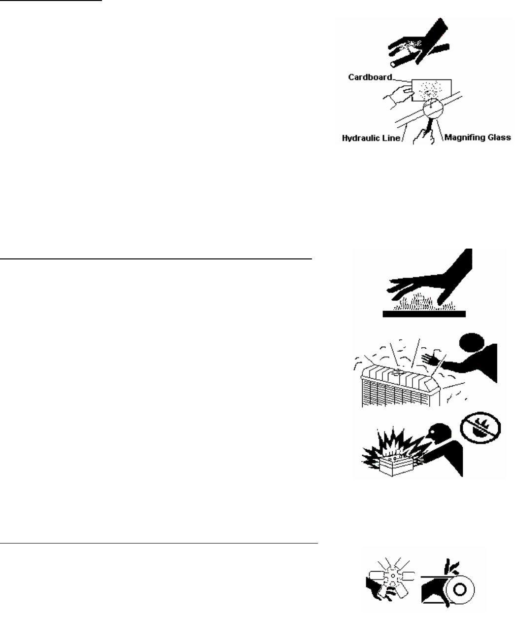
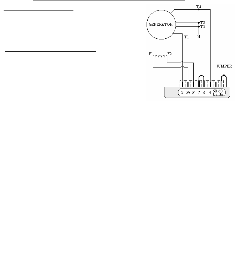
2. Connect the F+ and F- leads to the battery’s
corresponding positive and negative terminals. This
should be done using an appropriate length of lead wire
to separate the battery from the point of connection
(batteries may explode when exposed to an electric arc).
After 3 to 5 seconds, remove the F- lead. An inductive arc
should result. If no arc is drawn, repeat the procedure.
3. Reconnect the F+ and F- leads to the regulator. Restart
the generator and verify that terminal voltage is
developed. If terminal voltage does not develop, repeat
the field flashing procedure and / or consult the trouble
shooting section.
BEARING REMOVAL
Prior to performing this operation, it is suggested that the
alternator's shaft be rotated until two of the main rotor poles
are in a vertical position. Once the bearing bracket is backed
out, the rotor will drop on the main stator core. Having the
rotor in this position will limit the amount of rotor drop to that
of the air gap. Visually inspect the bearing bore for damage or
wear. If worn or damaged, replace prior to reassemble.
Opposite Drive End Bearing Bracket Removal.
Prior to proceeding with bracket removal, disconnect exciter
field leads F+ and F- from the automatic voltage regulator and
ensure that they are free to move when the bearing bracket is
removed. Remove the bearing bracket retaining bolts. Using a
pair of screw drivers, wedge the bracket off the frame. After
approximately 1/8 inch, the bracket will clear the locating
register on the frame and will drop until the rotor is resting on
the main stator core. Continue to pull the bracket free from the
bearing. Visually inspect the bearing bore and o-ring (if
equipped) for damage or wear. If worn or damaged, repair or
replace prior to reassembly.
Drive End Bearing Bracket Removal,
Two Bearing Units.
Remove any drive arrangement from the generator shaft
extension. Remove the bearing lock ring retaining screws.
There is no o-ring in the drive end bearing bracket. The shaft
extension must be supported before proceeding further. A
hoist and sling, jack, or some other means of support with a
capacity of 2 tons should be used.
Remove the bearing bracket retaining cap screws. Using a flat
bladed screw driver or chisel, pry the bracket back from the
frame. After approximately 1/8 inch, the bracket will clear the
locating register on the frame. Lower the shaft extension until
the rotor is resting on the main stator core. Continue to pull
the bracket free from the bearing. Visually inspect the
bearing bore for damage or wear. If worn or damaged, sleeve
or replace prior to reassembly.
Reassembly note: Before the bearing bracket is seated
against the frame, a threaded rod may be used to help align
the inner bearing cap with the bearing bracket.
BEARING REPLACEMENT
Using a bearing puller, remove the existing bearing. It is
strongly recommended that the bearing be replaced any time
the it is removed from the shaft. ALWAYS install the same
type and size bearing that was supplied as original
equipment. Order by part number from the parts list, and
include the unit serial number and part number when
ordering. Heat the bearing to a maximum of 100°C (212°F) in
an oven. Apply a thin coat of clean lubricating oil to the press
fit area of the rotor shaft. Using suitable heat resistant gloves,
install the bearing over the end of the shaft until it seats
against the shaft shoulder. The bearing should slide on the
shaft and be seated without excessive force. Should the
bearing bind on the shaft prior to being seated against the
shoulder, a piece of tubing slightly larger than the press fit
area can be used to drive the bearing to its final position.
Using light taps with a soft mallet, apply pressure to the inner
race only.
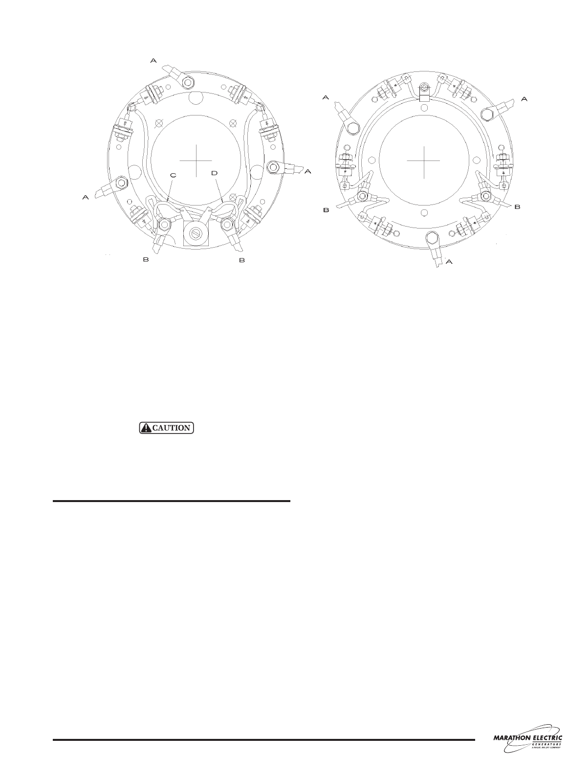
RECTIFIER ASSEMBLY REMOVAL
The rectifier assembly cannot be removed until the opposite
drive end bearing bracket and bearing have been removed
(see bearing removal procedure). Remove the three exciter
rotor leads from the heat sinks and the two main rotor leads
from the main rotor posts (see Figures 5). Remove the screws
securing the rectifier assembly and pull the assembly free
from the shaft.
DIODE REPLACEMENT
Prior to installing a replacement diode on the heat sink, apply
a thin film of conductive heat sink compound around the base
of the diode (do not coat the threads). When installing a diode
on the heat sink, care should be taken not to over torque the
retaining nut which could cause damage to the device. Torque
to 28 pound inches. If not damaged, the existing diode lead
wire may be unsoldered from the failed diode, and resoldered
on the replacement.
14
RETURNED GOODS
Contact Marathon Electric Manufacturing Corporation for
authorization before returning any product. We can not be
responsible for any items returned without authorization.
Single bearing generators must have their rotor
assembly properly secured to prevent damage during
transit to the factory, or to an authorized service cen-
ter.
TROUBLESHOOTING
This section is intended to suggest a systematic approach to
locating and correcting generator malfunctions. The section is
arranged according to the symptoms of the problem. The
steps have been arranged in an attempt to do the easy
checks first and prevent further damage when
troubleshooting a disabled machine.
The first step of troubleshooting is to gather as much
information as is possible from operating personnel and
individuals present during the failure. Typical information
includes: how long the unit had been operating; what loads
were on line; weather conditions; protective equipment that
did or did not function. In addition, information as to the
operating condition of the generator's prime mover is vital.
Has the prime mover been maintaining constant speed? If
not, have there been extended periods of under speed
operation? Has the prime mover experienced an over-speed
condition? If yes, what was the maximum speed, and how
long did the unit operate at that elevated speed?
The generator speed should be maintained at rated
nameplate value during all operating tests. The frequency of
the generator depends upon rotational speed. Most
regulators used with MagnaPLUS
®
generators have built in
under frequency protection such that if the speed is reduced
more than 5%, the voltage will drop off rather rapidly with
further reductions in speed.
15
430 FRAME 280 / 360 FRAME
A - Exciter Rotor Lead, B - Main Rotor Lead, C - Red (+) Suppressor Lead, D - Black (-) Suppressor Lead
FIGURE 5: ROTATING RECTIFIER ASSEMBLY
HIGH VOLTAGES MAY BE PRESENT AT THE GENERATOR’S TERMINALS WHEN THE UNIT IS RUNNING. SOME
ACCESSORY EQUIPMENT SUCH AS SPACE HEATERS MAY BE ENERGIZED FROM AN OUTSIDE POWER SOURCE
WHEN THE UNIT IS AT REST. TOOLS, EQUIPMENT, CLOTHING AND YOUR BODY MUST BE KEPT CLEAR OF
ROTATING PARTS AND ELECTRICAL CONNECTIONS. SPECIAL PRECAUTIONS MUST BE TAKEN DURING
TROUBLESHOOTING SINCE PROTECTIVE COVERS AND SAFETY DEVICES MAY BE REMOVED OR DISABLED TO
GAIN ACCESS AND PERFORM TESTS. BE CAREFUL. SERIOUS PERSONAL INJURY OR DEATH CAN RESULT FROM
THESE HAZARDS. CONSULT QUALIFIED PERSONNEL WITH ANY QUESTIONS.
GENERATOR PRODUCES NO VOLTAGE
CAUSE CHECK AND REMEDY
Voltmeter off or defective Check voltage with a separate meter at the generator terminals.
Incorrect or defective connections Verify generator connections. See drawings supplied with the generator or lead
connection diagrams in this manual. Inspect all wiring for loose connections, open
circuits, grounds, and short circuits.
Loss of residual Flash the field. Refer to field flashing in the service section. If the generator is equipped
with a PMG, field flashing is not necessary -- check regulator fuse and input power
from the PMG.
Defective diodes, suppressor, or windings Test the generator using the 12 volt battery test as specified in the testing section. If
the results indicate generator problems, perform insulation, continuity, and diode tests
as specified in the testing section.
Regulator protection operating Adjust regulator. Consult regulator manual.
Regulator inoperative Adjust or replace regulator. Consult regulator manual.
GENERATOR PRODUCES LOW VOLTAGE, NO LOAD
CAUSE CHECK AND REMEDY
Underspeed operation Check speed using a tachometer or frequency meter.
Voltmeter off or defective Check voltage with a separate meter at the generator terminals.
Incorrect or defective connections Verify generator connections. See drawings supplied with the generator or lead
connection diagrams in this manual. Inspect all wiring for grounds, open circuits and
short circuits.
Loss of regulator power Check regulator fuse and input power. Input power is produced by the generator’s
residual voltage or from an optional PMG.
Regulator adjustment Adjust regulator settings. Consult regulator manual.
Regulator incorrectly connected Review the generator connection diagram or reference the regulator manual.
Defective diodes, suppressor, or windings Test the generator using the 12 volt battery test as specified in the testing section. If
the results indicate generator problems, perform insulation, continuity, and diode tests
as specified in the testing section.
Regulator inoperative Adjust or replace regulator. Consult regulator manual.
16
WARNING
GENERATOR PRODUCES LOW VOLTAGE WHEN LOAD APPLIED
CAUSE CHECK AND REMEDY
Excessive load Reduce load. The load on each leg should be evenly balanced, and rated current
should not be exceeded on any leg.
Large motor starting or low Motor starting currents are too large for the generator. When starting multiple motors,
load power factor sequence the motors and start the largest motors first. Reduce lagging power factor
load.
Driver speed droop or belt slip Check driver. If belt driven, check belt tension. Check under frequency setting on
regulator. Under frequency voltage roll-off may be activated.
Reactive droop If the generator is equipped for parallel operation, some droop is normal as reactive
load increases. When operating as a single unit, the parallel CT can be shorted to
eliminate this effect. Refer to Regulator manual.
Line drop If voltage is proper at generator terminals but low at load terminals, increase external
wire size.
Defective diodes, suppressor, or windings Test the generator using the 12 volt battery test as specified in the testing section. If
the results indicate generator problems, perform insulation, continuity, and diode tests
as specified in the testing section.
GENERATOR PRODUCES FLUCTUATING VOLTAGE
CAUSE CHECK AND REMEDY
Fluctuating engine speed Check engine and governor systems for malfunctions. Check load for fluctuation.
Regulator stability Adjust Regulator stability. Refer to Regulator manual.
Regulator external rheostat Replace defective or worn rheostat. Use shielded cable to minimize electrical noise.
Defective rectifier assembly Check assembly for loose connections. Test the diodes as specified in the test section.
Loose terminal or load connections Improve connections both mechanically and electrically.
Defective regulator Replace regulator.
GENERATOR PRODUCES HIGH VOLTAGE
CAUSE CHECK AND REMEDY
Faulty metering Check voltage with separate meter at generator terminals.
Incorrect connections Verify generator connections. Refer to drawings supplied with the generator or
connection diagrams in this manual.
Regulator adjustments Adjust regulator. Consult regulator manual.
Leading power factor Check the power factor of the load. If power factor is leading, change load
configuration. Excessive leading power factor (capacitors) can cause voltage to climb
out of control.
Incorrect regulator connection Verify regulator voltage sensing is connected correctly. Consult regulator manual.
Defective regulator Replace regulator.
17
GENERATOR BUILDS VOLTAGE FROM STARTUP,
THEN GOES TO LOW (RESIDUAL) VOLTAGE
CAUSE CHECK AND REMEDY
Regulator protective circuit operating Check indicators on regulator. Correct problems and adjust regulator as is required.
Refer to regulator manual.
GENERATOR IS OVERHEATING
CAUSE CHECK AND REMEDY
Generator is overloaded Reduce load. Check with ammeter and compare with nameplate rating.
Clogged ventilating screens Clean air passages.
High room temperature or altitude Improve ventilation or reduce load.
Insufficient circulation of cooling air Generator location and enclosure design must provide adequate air flow and
minimize recirculation of hot air.
Unbalanced load The load on each leg should be as evenly balanced as possible and should not exceed
rated current on any one leg.
GENERATOR PRODUCES MECHANICAL NOISE
CAUSE CHECK AND REMEDY
Defective bearing Replace bearing.
Loose or misaligned coupling Tighten, realign, or replace coupling.
Belt slap or loose guards Check belt tensioning. Check belt guard fasteners.
EQUIPMENT RUNS NORMALLY ON UTILITY POWER,
BUT WILL NOT RUN ON GENERATOR SET
CAUSE CHECK AND REMEDY
Distorted voltage waveform Analyze load. Excessive SCR (thyristor) loading will cause distortion. Some equipment
may be sensitive to distorted waveforms. Refer to Marathon Electric..
Improper generator voltage or frequency Check name plates of devices comprising the load. Compare required voltage and
frequency with that of the generator. Adjust driver speed and/or generator voltage as
necessary to match generator output to load requirements.
Compare required voltage, frequency, and KVA with generator nameplate to ensure adequate generator capacity. If in
doubt, consult Marathon Electric for information regarding generator capacity.
18
SPECIFICATIONS
19
MODEL / FRAME SIZE
EXCITER RESISTANCE
STATOR ROTOR
281, 282, 283, 284, 285, 286, 287 18.0 .120
361, 362, 363 -- three phase 23.5 .120
361, 362, 363 -- dedicated single phase 23.0 .135
431, 432, 433 -- three phase 18.5 .120
431, 432 -- dedicated single phase 18.0 .105
EXCITER FIELD
MODEL GENERATOR RESISTANCE NO LOAD VOLTS
STATOR* ROTOR 480 V / 60 HZ
281PSL1500 4.20 .400 11.0
281PSL1501 4.15 .400 11.0
281CSL1502 0.47 0.72 6.40
281PSL1502 3.20 .439 9.0
282PSL1703 1.07 0.34 14.70
282CSL1504 1.24 0.80 6.20
282PSL1704 1.07 0.34 14.70
282CSL1505 0.87 0.90 5.80
282PSL1705 0.74 0.37 14.35
283CSL1506 0.54 1.00 8.20
283PSL1706 0.45 0.40 12.95
283CSL1507 0.44 1.18 9.20
283PSL1707 0.39 0.46 11.20
284CSL1508 0.29 1.36 10.00
284PSL1708 0.27 0.52 14.18
284CSL1542 0.27 1.36 8.30
284PSL1742 0.22 0.54 14.00
285PSL1700 0.20 0.58 11.90
286PSL1701 0.14 0.72 10.68
287PSL1702 0.12 0.79 10.9
361CSL1600 .381 .750 11.8
361CSL1601 .264 .810 12.5
361CSL1602 .181 .990 14.1
362CSL1604 .138 1.05 12.2
362CSL1606 .098 1.20 10.8
363CSL1607 .069 1.37 12.2
431CSL6202 .021 .811 15.1
431CSL6204 .048 .637 13.6
431CSL6206 .037 .679 13.82
431CSL6208 .013 .715 12.20
432PSL6210 .021 .811 15.1
432PSL6212 .023 .866 14.1
433PSL6216 .012 1.067 16.2
433PSL6220 .012 .974 15.6
DEDICATED EXCITER FIELD
SINGLE GENERATOR RESISTANCE NO LOAD VOLTS
PHASE STATOR ROTOR 480 V / 60 HZ
281PSL1500 4.20 .400 11.0
281CSL1513 0.47 0.72 4.3
281PSL1511 1.420 .381 8.3
281PSL1512 1.106 .395 8.1
281PSL1513 .632 .430 8.7
282CSL1515 0.21 0.82 6.2
282PSL1714 0.19 0.35 13.0
282PSL1715 0.19 0.35 13.0
282PSL1716 0.11 0.36 12.4
283CSL1517 0.08 1.14 12.7
283PSL1717 0.5 0.41 11.8
283PSL1718 0.07 0.46 10.1
284CSL1518 0.06 1.41 12.5
284CSL1550 0.05 1.48 16
284PSL1750 0.05 0.55 11.1
285PSL1711 0.04 0.58 11.0
286PSL1712 0.03 0.71 9.7
287PSL1713 0.02 0.78 12.3
361PSL1611 .070 .750 17.5
361PSL1612 .043 .857 16.1
361CSL1613 .037 .926 13.6
362CSL1615 .019 1.20 17.0
363CSL1617 .012 1.35 23.0
431PSL6222 .025 .516 9.9
431PSL6224 .013 .615 13.8
431PSL6226 .009 .643 15.1
432PSL6228 .007 .852 11.2
* Stator resistance measured line to line in a high wye
connection.
20
PARTS LIST – SINGLE BEARING
Typical Generator Cross Section
1
2
3
4
5
7
6
8
9
11
10
12
13 14
15
17
18
16
20 19
Reference Part Name Reference Part Name
Number Number
1 End Bracket (under end cover 360 & 430 frames) 11 Main Stator
2 Bearing 12 Main Rotor
3 O-ring (280 and 360 frame only) 13 Rotor Integral Keyway
4 Rectifier Assembly 14 Fan
5 Air Intake Cover 15 Mounting Adapter (SAE)
6 Exciter Rotor 16 Shaft
7 Exciter Stator 17 Drive Hub
8 Link Board (terminal block) 18 Drive Disk (SAE)
9 Conduit Box 19 Exhaust Screen (drip cover not shown)
10 Generator Frame 20 Mounting Base
Note: Illustration above is a 360 frame MagnaPLUS
®
. Other Frame sizes are typical. Optional PMG not shown. The generator
model and serial numbers are required when ordering parts.
DESCRIPTION PART NUMBER
1. END COVER 02HB30
2. ROTOR BEARING 02BRG30
3. EXCITER ROTOR 02RTR30EXC
4. EXCITER STATOR 02STA30EXC
5. GENERATOR ASSEMBLY 02GEN1517
VOLTAGE REGULATOR 06REG350SE
“MAGNAPLUS” SERIES EXCITER TYPE GENERATOR ASSEMBLY
21
MARATHON SE350 VOLTAGE REGULATOR
The SE350 electronic voltage regulator is designed to control the output of a brush less AC
generator by regulating the current into the exciter field. Features include frequency compensation,
automatic voltage build-up and EMI suppression. The SE350 attaches to the generator with spade
type wire terminals for a secure connection. The SE350 has three adjustable potentiometers for fine-
tuning the output voltage, stability and under frequency. The regulator is encapsulated in a protective
plastic shell and back filled with a sealing compound, which provides protection from environmental
hazards.
SE350 Specifications:
Sensing and Power Input 190 – 240V AC
Burden 500VA
Output Power – Continuous 73V DC at 3.5 Amps DC (255W)
Output Power – Forcing 105V DC at 5 Amps DC (525W)
(240V AC input Power)
Regulation 1.0%
Frequency Compensation Adjustable
Roll Off Frequency 54 - 61 Hz for 60 Hz Operation
45 - 51 Hz for 50 Hz Operation
Voltage Build-Up Internal provisions for automatic voltage build-up
From generator residual voltage as low as 10V AC
EMI Suppression Internal Electromagnetic Interference Filter (EMI Filter)
22
3 ADJUSTABLE POTENTIOMETERS, ACCESSED FROM OTHER SIDE
JUMPER JUMPER
MARATHON SE350 VOLTAGE REGULATOR
WARNING: To prevent personal injury or equipment damage, only a qualified service
technician should install, operate or service this device.
IMPORTANT: DO NOT megger or high-pot the generator while the regulator is
connected. DO NOT high-pot the regulator.
VOLTAGE ADJUST:
A screwdriver adjustable potentiometer adjusts the generator output voltage. Adjustment
clockwise increases the generator output voltage.
STABILITY ADJUST:
System stability is the ability of the generator to respond to load transients. Decreasing
the stability makes the generator less sluggish and faster to respond to load transients. If
the stability of the regulator is decreased too much, the generator will tend to hunt under
steady state conditions. A screwdriver adjustable potentiometer adjusts the system
stability. Adjustment clockwise increases the stability. Increasing the stability increases
the response time of the generator. Conversely, decreasing the stability decreases the
response time of the generator.
V/HZ ROLL-OFF FREQUENCY SELECTION
:
The roll-off point is the frequency where the generator voltage starts to decrease. This
reduces the Kilowatt load to the engine, which allows the engine to recover in speed
under any load transient condition. Use jumper to select 50 Hz or 60 Hz. The screwdriver
adjustable potentiometer sets the roll-off frequency from 54-61 Hz in the 60 Hz setting or
from 45-51 Hz in the 50 Hz setting.
The SE350 has the roll-off point preset to 58 Hz in the 60 Hz mode and 48 Hz in the 50
Hz mode. To change the roll-off point, adjust engine speed to the desired rated speed. (50
or 60 Hz). Set the voltage to the desired setting at rated speed. Adjust engine speed to the
desired roll-off point. Turn the potentiometer counterclockwise until the voltage starts to
drop off. Then adjust the potentiometer clockwise until the voltage returns to rated. Re-
adjust engine speed to rated speed.
23
EXCITER POWER CIRCUIT:
Connect the regulator wire F+ to the generator
F+ or F1 field terminal. Connect the regulator
wire F- to the generator F- or F2 field terminal
SENSING / POWER INPUT CIRCUIT:
Input power and sensing is achieved through
terminals 3 and 4. The voltage input requirement
of the SE350 is 190 to 240V AC.
A 4 Amp 250V – 5x20 mm fuse is supplied with
the re
g
ulator.
MARATHON SE350 VOLTAGE REGULATOR
START-UP PROCEDURE:
Ensure the voltage regulator is correctly connected to the generator. Refer to the specific connection
diagram supplied with the generator. Set the regulator voltage adjust to full counter-clockwise
(minimum voltage level). Set the stability control full clockwise (maximum stability level). Connect the
positive lead of a 100V DC voltmeter to F1 and the negative lead of the voltmeter to F2 or use an
appropriate AC voltmeter on the generator output leads.
Start and run the generator at no load and rated speed. The generator voltage should build up to a
minimum level. (Actual level is dependent upon connection). If it does not build up, refer to field
flashing section in generator manual. Slowly adjust the voltage control until the generator voltage
reaches the normal value. Turn the stability adjust counter-clockwise until instability is shown on the
voltmeter. With the system operating in an unstable condition, slowly adjust the stability control
clockwise until generator stability is reached. Interrupt regulator power for a short time (approximately
1-2 seconds). If the generator remains stable no further adjustment is necessary. If the generator does not
remain stable increase the stability slightly and interrupt regulator power again. Repeat this procedure
until system stability is reached and maintained.
TROUBLESHOOTING
SYMPTOM CAUSE ACTION
Residual Voltage
No Output
Residual Voltage at regulator power
input wires 3&4 below 10V AC.
Acceleration time to rated speed too long.
Field leads F1, F2 not connected.
Power input leads not connected.
Blown or missing fuse.
Defective regulator.
Defective generator.
Check wiring diagram for proper
connections.
Flash generator field.
Reduce acceleration time.
Interrupt power input to regulator after
achieving rated speed.
Connect field leads F1, F2.
Connect power input leads 3,4.
Replace fuse.
Replace regulator.
Consult generator manual.
Output Voltage Low Incorrect connections.
Voltage adjust turned down.
Defective regulator.
Check wiring diagram for proper
connections.
Rotate voltage adjust CW until desired
voltage is reached.
Replace regulator.
Output Voltage High Voltage adjust turned too high.
Rotate voltage adjust CCW until desired
voltage is reached.
Output Voltage High
No Adjustment
Defective regulator. Replace regulator.
Generator Output
Voltage Hunting
Stability adjust not set properly. Rotate the stability adjust in a CW
direction until hunting stops.
Poor Regulation Defective regulator. Replace regulator.
24
120 / 240 VOLT CONNECTION “M” SERIES EXCITER TYPE
25
RESISTANCE CHART
Marks Color
Main Stator Less Than 1.0
Ohm / Phase
T1-T2 T3-
T4
Black / Black
Main Rotor 2.10 N/A N/A
Exciter Stator 23.0 – 28.0 F+ – C Black / Black
Exciter Rotor 0.655 – 0.720 N/A N/A
Aux. Winding 1.0 – 1.4 E1 – E4 Black / Black
SECTION 4
“INSTALLATION”
SAFETY PRECAUTIONS 1-2
Hot Piping
Dangerous Fuels
Explosive Battery Gases
Electrocution
Moving Parts
High Voltage
Explosion
Hot Coolant
Lethal Exhaust Gas
Excessive Noise
Electrical Shock
Backfire
Flash Fire
Fire Hazard
Marine Application
Unit Starts Without Notice
Loose Components
GENERATOR INSTALLATION in RECREATIONAL VEHICLES 3-6
Introduction
Marine Application
General Information
Specification Charts
Fuel Consumption in Gallons per Hour
Installation Factors
Generator Compartment Size
Compartment Frame
Air Requirements
SYSTEMS CONNECTION 7-10
Remote Radiator Cooling System
Fuel System
Exhaust System
Fuel Line Diagram
ELECTRICAL CONNECTIONS 11-13
Electrical Wiring
AC Load Lead Connections
Motor Loads
Kilowatt De-Rating
Electrical Loads
Appliance Loads
Extension Cords
SAFTEY PRECAUTIONS
A generator set can be potentially dangerous if not properly maintained and operated. The best Safe
Guard against a dangerous situation is education, good judgment and common sense. For safe trouble free
operation of your generator set some general precautions are listed below. Be sure to read, understand and
follow these precautions. Please call Power Technology Southeast, Inc. with any concerns you may have with
your generator set.
1) HOT PIPING: An engine and exhaust system may get extremely hot while running. Do not work on a
generator set until it has sufficiently cooled.
2) DANGEROUS FUELS: Use extreme caution when handling, storing and using fuels. All fuels are highly
explosive in a vaporous state. Store fuel in a well ventilated area away from spark producing
equipment. Keep fuels and all chemicals out of the reach of children. Never add fuel to the
tank while the engine is running. Spilled fuel may ignite on contact with hot parts or from
ignition spark. Always keep fuel lines and connections tight and in good condition. Don’t
replace flexible fuel lines with rigid lines. If you notice any fuel leakage, fuel accumulation
or electrical sparks, DO NOT OPERATE THE GENERATOR SET.
3) EXPLOSIVE BATTERY GASES: The gases generated by a battery being charged are highly explosive.
Do not smoke or permit any flames or sparks to occur near a battery at any time, especially
when it is being charged. Avoid contact between terminals with tools to prevent sparks and
possible burns. Always remove wristwatch, rings, or other jewelry before handling a battery.
Any compartment containing batteries should be well ventilated to prevent the accumulation
of explosive gases. To avoid sparks never disturb the battery charging connections while the
battery is being charged. Always turn off the battery charger before disconnecting terminal
clips.
4) ELECTROCUTION: Failure to install a generator set with an electrical system consistent with governing
regulations and standards is UNLAWFUL and may cause ELECTROCUTION of vehicle
occupants. Your generator set must not be used to “Back Feed” by connecting it to a building
or outdoor electrical circuit. Back feeding can cause serious injury or death to utility
personnel working to repair a power outage and may also seriously injure persons in your
vehicle. Unauthorized connections are unlawful in some states and/or localities. A transfer
switch must be installed to prevent interconnection of the generator set power and outside
power.
5) MOVING PARTS: Keep hands, feet, and clothing away from belts and related pulleys when unit is running.
Replace guards, covers, and screens before operating the generator set. Serious personal
injury may occur from contact with moving parts.
6) HIGH VOLTAGE: Remember the function of a generator set is to produce electricity. Wherever electricity
is present there is a potential danger of electrocution. Apply the same precautions to the
vehicles electrical appliances as you would for any home appliance. Keep away from
electrical circuits and wiring while the generator set is running. Have electrical service
performed only by qualified electricians. Be sure any unauthorized person; especially
children are denied access to the generator set. Keep the compartment door securely latched
or locked at all times. Be sure the generator is properly grounded. Never touch electrical
leads or appliances with wet hands, or when standing on wet ground.
1
7) EXPLOSION: Never connect the negative (-) battery cable to the positive (+) connection terminal of the
starter solenoid, or test the battery by shorting terminals together. This could ignite fuel
vapors or cause the battery to explode. To disconnect the battery remove the negative
battery cable first and reconnect it last. Do not modify the fuel tank or propulsion engine
fuel system. Your vehicle must be equipped with a fuel pick-up arrangement as described
in the Fuel System section of this manual. Fuel tank and installation must conform to
applicable regulations.
8) HOT COOLANT: Allow engine to cool and release pressure from the cooling system before opening the
radiator pressure cap. To release the pressure, cover the radiator cap with a thick cloth then
turn it slowly counterclockwise to the first stop. After the pressure is released and the
engine has cooled, remove the cap.
9) LETHAL EXHAUST GAS: When installing an exhaust system position the tail pipe end so that the
discharged gases may not be drawn into the vehicle interior through windows, doors, air
conditioners, etc. The engine powering your generator set discharges deadly carbon
monoxide as part of the exhaust gas when running. It is essential that the exhaust system be
leak proof and routinely inspected.
10) EXCESSIVE NOISE: Never operate the generator set without an adequate muffler or with a faulty
exhaust system. Exposure to excessive noise can lead to a hearing impairment.
11) ELECTRICAL SHOCK: A battery can cause electrical burns and shocks. Use reasonable care when
working near the battery to avoid electrical connections by contacting the battery terminals
with tools. Remove wristwatch, rings and all jewelry when working on the generator set.
12) BACKFIRE: A sudden backfire can cause serious burns. Do not operate your generator set without its air
cleaner / flame arrestor in place.
13) FLASH FIRE: A sudden flash fire can cause serious burns. To avoid the possibility of a flash fire do not
smoke or permit a flame or spark to occur near the carburetor, fuel lines, fuel filter, fuel
pump or other potential source of spilled fuel or vapors.
14) FIRE HAZARD: Be careful when parking your vehicle to prevent grass fires from being started by hot
exhaust gases or exhaust system. Keep away from hot engine and generator parts to avoid
burning yourself. Keep the generator set and compartment clean and free of debris,
especially combustible materials. Never store fuel, oil or rags in the generator
compartment.
15) MARINE APPLICATION: RV generator sets do not comply with United States Coast Guard (USCG)
requirements. They must not be used for marine applications. Use only generator sets
specified for marine use in a marine application. USCG regulation 33CFR183 requires a
generator set to be ignition protected for use in a gasoline-fueled environment.
16) UNIT STARTS WITHOUT NOTICE: To prevent accidental starting on the units with remote start /
stop switch, always disconnect the battery by removing the negative (-) terminal first and
then the positive (+). Always disconnect the unit in this manner before working on the
generator or any equipment connected to it.
17) LOOSE COMPONENTS: Periodically check for and tighten any fasteners that may have become loose
from vibration or road shock. Serious damage may possibly occur if components become
dislodged or misaligned.
2
GENERATOR INSTALLATION
In RECREATIONAL VEHICLES
INTRODUCTION
Use this section as a guide when installing a generator set in a recreational vehicle, and then refer
to the appropriate operation section for specific instructions. When installing a EC generator set the
installation must comply with the current Safety Standards of ANSI / RVIA EGS-1-2003, ANSI A 119.2
/ NFPA 501C and applicable articles of ANSI / NFPA 70 of the National Electrical Code. Generator set
installations must also comply with state and local requirements.
MARINE APPLICATION
EC generator sets do not comply with United States Coast Guard (USCG) requirements and must
not be used for marine applications. Use only generator sets specified for marine use in marine
installations. USCG regulation 33CFR183 requires a generator set to be “ignition protected” when used
in a gasoline fueled environment.
GENERAL INFORMATION
This information section covers the EC generator set models listed below. To determine which
model is involved, check the model number found on the Power Technology nameplate attached to the
frame of the generator being installed. Follow all instructions to ensure proper installation and operation.
Each generator set features a Kubota diesel engine, rotating-field alternating current generator,
and a control box. The generator is directly connected to the engine for permanent alignment. Each
control box includes a Start / Stop switch, and a On /Off switch to reset the control module or lockout
any remote switch to prevent starting while service is being performed. After the set is attached to the
frame of the vehicle, all that is usually required to make it operational is the following.
1. Attaching the exhaust system.
2. Add proper amount of radiator coolant.
3. Add oil to crankcase, to the dipstick FULL mark.
4. Connect fuel lines, remote switch, load leads and battery terminals.
(Consult the Specification Charts on the Following Pages for Requirements)
NOTE: * Dimensions and Weight may differ depending on options and configuration variables.
3
MODELS PT20-EC PT20-ECRR PT25-EC PT25-ECRR
DIMENSIONS L x W x H * 56” x 28 ” x 28 ” 56” x 28 ” x 28 ” 56” x 28 ” x 28 ” 56” x 28 ” x 28 ”
WEIGHT * 950 lbs. 950 lbs. 950 lbs. 950lbs.
ENGINE Kubota V2203-M Kubota V2203-M Kubota V2003-M-T Kubota V2003-M-T
RPMs 1800 1800 1800 1800
KW RATING 20 20 25 25
AC VOLTAGE 120 / 240 120 / 240 120/240 120/240
AMPERAGE 166/83 166/83 200/100 200/100
Hz 60 60 60 60
PHASE 1 1 1 1
GENERATOR
COMPARTMENT
FREE AIR OPENING
400
Square Inches
400
Square Inches
400
Square Inches
400
Square Inches
RADIATOR AIR
REQUIREMENTS
2120 CFM 2120 CFM 2120 CFM 2120 CFM
SPECIFICATION CHARTS
FUEL CONNECTION ¼” NPT
FUEL RECOMMENDATION DIESEL FUEL No.1-D or No.2-D ASTM / D975
BATTERY VOLTAGE 12 VOLTS DC
BATTERY CRANKING AMPS 420
BATTERY COLD CRANKING AMPS 590 MINIMUM
BATTERY GROUND NEGATIVE
CHARGING AMPS. 40
FUEL CONSUMPTION IN GALLONS PER HOUR
LOAD PERCENTAGE 20KW 25KW
25% .39 GPH .45 GPH
50% .79 GPH .90 GPH
75% 1.18 GPH 1.35 GPH
100% 1.57 GPH 1.80 GPH
INSTALLATION FACTORS
Each generator set is received as a unit except for the optional exhaust system components,
which are shipped loose for assembly after the set is installed in the vehicle. When preplanning the
installation, the following factors must be considered.
1. COMPARTMENT SIZE: Will there be sufficient room around the set to maintain
the minimum clearance of one (1) inch?
2. AIR REQUIREMENTS: Are the compartment air inlets and outlets sized to allow
adequate circulation of air for cooling and combustion?
3. COMPARTMENT FLOOR: Is the compartment floor strong enough to support the
weight of the generator set?
4. COOLING SYSTEM: Is the cooling system large enough to adequately cool the
generator set? **
5. FUEL SYSTEM: Is the fuel system properly designed to prevent fuel
starvation of either the main engine or generator engine?
6. EXHAUST SYSTEM: Will the exhaust system meet all Local, State and Federal
safety requirements?
7. ELECTRICAL CONNECTIONS: Will all systems, (battery, load and remote switch)
be compatible with the vehicles system?
** NOTE: When using a radiator not supplied by Power Technology consult your radiator
manufacturer to ensure that heat rejection values are met.
4
GENERATOR COMPARTMENT SIZE
In planning the size of the generator compartment allow for the minimum clearance of one (1)
inch necessary to adequately cool the generator set. The thickness of insulation and sound deadening
material used to line the compartment must be taken into consideration when planning this clearance. To
maintain minimum clearance it may be necessary to enlarge the compartment.
NOTE: For Gensets mounted inside an enclosure please refer to the section on “Generator Enclosures”
for additional information and mounting requirements.
The generator set must be securely fastened to avoid unwanted movement from vibration and
road shock. If the unit is equipped with a mounting tray the tray is usually supported with structural
framing. Be sure to use all mounting holes in the tray to secure the tray to the structural framing. Units
not equipped with mounting tray are secured by attaching Genset mounts (two front and two rear)
directly to the structural framing. Skid mounted units can either be affixed to a tray for tray mounting or
attached directly to the structural framing. The generator is easily moved in and out of the coach by
incorporating a slide rack carriage with rollers into the structural framing. When designing the
compartment allow sufficient access for routine maintenance and for removal when major service is
required. Also keep in mind that the compartment or door must have an air intake opening equal to or
greater than that specified under the “Air Requirements” section of this manual. Make sure that the
compartment is vapor tight and completely sealed off from the inside of the vehicle to prevent any
hazardous fumes from entering the vehicle. Avoid road splash and the possibility of igniting
combustible materials beneath the coach by enclosing all unnecessary free space beneath the generator
compartment.
Line the compartment with a good sound deadening material. The material selected must be
fireproof or highly fire resistant. 3-layer foam sound mat is very efficient for absorbing generator noise.
This type of material is easily cut to size and can be quickly installed using the appropriate fire resistant
adhesive. Other materials such as fiberglass insulation with heat barrier may also be used.
NOTE: Since a Genset is flexibly mounted the minimum clearance of one (1) inch will assure that the
unit will not rub the sides of the compartment while the unit is in operation or while the vehicle is in
transit.
COMPARTMENT FRAMING
The generator must be bolted to a structural frame, which is either bolted or welded to the frame
of the vehicle. This structural frame must be designed to withstand a minimum force of 5Gs in any
direction. The structural frame must support the entire outer perimeter and center section of the unit’s
base. Additional framing may be required if excessive movement or vibration occurs.
AIR REQUIREMENTS
Each Genset is equipped with a high ambient temperature shutdown switch and a high water
temperature shutdown switch, which will automatically shut down the Genset if the ambient temperature
or water temperature rises too high. To prevent the generator set from shutting down make sure the
compartment openings are large enough to allow adequate circulation of cooling air. The minimum free
air opening into the compartment is 400 sq. in. or 2580 sq. cm. Remember that louvers, screens and
protective grills will restrict airflow. A relatively open mesh screen can restrict airflow by as much as
45%. The intake opening will need to be increased in size to compensate for such restrictions.
NOTE: Ambient temperature is defined as the generators normal operating temperature within its
mounting area. In an RV application this area is referred to as a compartment or enclosure.
5
AIR REQUIREMENTS CONT’D
*Combustion Air Temperature: The output of the engine will decrease about 1% for
every 10°F of air temperature above 77°F or 25°C.
IMPORTANT: Insulation and Sound Absorbing Material used inside of the generator compartment
Must Not reduce the specified airspace clearance of one (1) inch or restrict the airflow around the
generator. Such reduction in airspace may lead to an overheating situation and reduced generator
performance. Also be sure the air inlet and outlet openings meet the specified requirements. Allow
clearance inside the generator compartment for easy access when routine maintenance is required.
WARNING: The generator compartment Must Be sealed to prevent hazardous fumes and vapors from
entering the vehicles other compartments and interior spaces. Plugging holes and sealing all seams will
greatly reduce this hazard.
WARNING: Drip Proofing! When installing a generator, the area directly beneath the generator end of
the unit must incorporate a non-flammable barrier. This barrier needs to be made of sufficient material
able to withstand and prevent molten metal, burning insulation, flaming or sparking particles from
penetrating the compartment floor or dripping beneath the compartment.
6
20 / 25 KW
ENGINE SPEED IN RPM 1800
OUTPUT IN HORSEPOWER 32.5 / 36.6
WATER FLOW – GAL. / MIN. 8.75
ENGINE INLET WATER TEMP. N/A
THERMOSTAT – RATING 180°F
THERMOSTAT FULL OPEN 195°F
ENGINE OUTLET WATER TEMP.MAX. 235°F
HIGH TEMP. SHUTDOWN SWITCH 230°F
HEAT REJECTION – BTU / MIN. 1650
HEAT REJECTION – BTU / HR. 99,000
REMOTE RADIATOR
AIR FLOW – CU. FT. / MIN.
1920
ENGINE OIL TEMP. MAX. 268°F
COMBUSTION AIR TEMP. * N/A
SYSTEMS CONNECTION
REMOTE RADIATOR COOLING SYSTEM
Use the following data in designing and installing the generator set cooling system. To insure a
safe effective installation, be sure the cooling system selected follows these parameters. Power
Technology offers radiator assemblies, which meet these requirements and will adequately cool the
generator. Select the radiator assembly best suited for the generator installation.
Due to the multitude of coach manufacturers and the variety of generator installations, only
general guidelines are provided. Adapt these recommendations to the installation. In a typical
installation the radiator assembly is installed in the same compartment as the generator. If a blower fan
radiator assembly is used, cooling air is drawn across the generator and engine and then through the
radiator. If a suction fan radiator assembly is used the suction fan pulls cooling air through the radiator
and then past the generator set. If the radiator assembly alone is used the installer must supply an electric
blower or suction fan to circulate the cooling air. See the specification table for total air requirements.
Depending on space limitations the radiator can be located in front of, adjacent to, or in a ventilated
remote location from the engine compartment, no more than 10 feet from the generator. To prevent re-
circulation of heated air be sure to maintain a tight seal between the radiator and the discharge chute.
Generally the discharge chute opening should be approximately one and one half times the size of the
radiator core.
NOTE: If the radiator is to be located in a compartment separate from the engine, refer to the engine
combustion air and heat rejection requirements of the generator and engine block when designing the
cooling system. A supplemental cooling fan capable of 500cfm (28.m³/min) should be installed to
supply air to the generator compartment for these requirements.
Connect the radiator fan motor to the generator output leads L1 and L2. Be sure the radiator fan
motor rotates in the correct direction and is of the proper voltage. To protect against overload and short
circuits it is recommended that the motor be adequately fused. Install fuses between the motor and
L1 / L2 connection. A close relationship exists between the cooling system design and the generator
compartment size. Availability of space is often the determining factor in the cooling system design. See
the “Compartment Size” section of this manual prior to designing and installing the generator cooling
system.
CAUTION: The fill inlet and reservoir tank must be located at the highest point in the cooling system.
If the fill inlet is not located as directed, coolant will not completely fill the engine. The cooling system
must be purged of all air pockets for the system to function properly. If air pockets remain in the engine
the high water temperature shutdown switch will malfunction and cause the engine to over heat. Also if
the cooling system is not completely full, the low water level shutdown switch will prevent normal
engine operations.
REMOTE RADIATOR ASSEMBLY
7
SYSTEMS CONNECTION
FUEL SYSTEM
The diesel fuel system for the generator set must be designed to operate independently from the vehicles
main engine if both engines are to be operated at the same time. The best way to do this is to have separate fuel
tanks, but this is usually impractical because of space restrictions. In most installations both engines operate
from a common fuel tank with separate pick-up tubes for each engine, not a Tee fitting arrangement. This
prevents either or both engines from being starved for fuel. The generator set fuel pick-up tube is generally
shorter than the vehicles; therefore fuel may not be available to the generator when fuel supply is low. This will
prevent the generator from depleting the fuel supply needed by the main engine.
NOTE: Using a simple Tee fitting to supply both engines from a common fuel line is not recommended. This
practice may possible cause a fuel starvation situation to either or both engines. Also, if excessive pressure were
to build up in the main supply line it could possible cause a failure of the generators fuel lines or connectors and
a hazardous fuel leak may occur.
Care must be taken when routing the fuel line from the main tank to the generator set. Keep the fuel line
as short as possible while maintaining adequate clearance from the exhaust system. Fuel lines must be run along
the frame side rails or coach under carriage. Never run fuel lines inside of the coach. Securely fasten the fuel
lines with hardware that is recommended for the type of fuel line used. The fuel lines should enter the generator
compartment at a point nearest to the generators fuel line connection fittings. Allow for a minimum of 8inches
of flexible fuel line to make the connection. Use proper size fuel line to accommodate the fuel flow needed.
Steel fuel line or high quality fuel hose is recommended, either one should have a minimum of ¼” ID and
strong enough to withstand road and climatic conditions.
EXHAUST SYSTEM
Exhaust system components will vary from one installation to another; therefore a muffler and tailpipe
may not always be furnished with the Genset. However, it is imperative to install a muffler and tailpipe to
reduce exhaust noise and direct exhaust gases beyond the vehicles perimeter and away from the normal head-on
air stream. Install a tail pipe with as few bends as possible to prevent excessive backpressure. A properly
installed exhaust system must be vapor tight, quiet and completely safe for the vehicle, its occupants and
surroundings. Installation of an approved Spark Arrestor is required.
The exhaust system components must be approved and properly installed to meet the codes and
regulations required by Federal and State agencies.
Laws pertaining to application and maintenance of a Spark Arrestor may vary depending on your
location and State regulations. Federal laws apply on Federal lands. If a generator is used in a forest, on brush or
grass covered unimproved land it must be equipped with a Spark Arrestor. It is the responsibility of the vehicle
owner or operator to install and maintain the entire exhaust system in good working condition.
CAUTION: Any person (s) who installs an unapproved Muffler, Spark Arrestor or other exhaust system
component, and/or modifies an exhaust system or component that may result in a hazardous condition is liable
for damages, injuries or warranty expense caused by such unapproved installation and/or modification.
8
EXHAUST SYSTEM
IMPORTANT SAFETY TIPS:
When exhaust system components are not furnished by Power Technology as part of the Genset, the
installer is responsible for meeting the following requirements.
1) Only use exhaust system components, which do not restrict exhaust flow. A restricted exhaust
system will create excessive backpressure and may cause poor engine performance and possible
engine damage. The maximum allowable backpressure for the engines listed in this manual is
1.57in Hg, (40mmHg).
2) Muffler shall be fabricated of aluminized steel or other corrosion resistant material and be of a
welded or crimp construction.
3) Maintain a minimum of 3 inches (76mm) between the exhaust system components and any
surrounding combustible materials. If the minimum clearance cannot be maintained, an
insulating shield must be installed to prevent the combustible material from exceeding
temperatures of 117°F
(65°C) above ambient temperature.
4) Extend the exhaust system a minimum of 1 inch (25mm) beyond the vehicles perimeter. Never
terminate the exhaust system underneath the vehicle.
5) Terminate the exhaust system in a direction, which prevents the exhaust gases from being drawn
back into the generator compartment and re-circulated.
6) If the exhaust system in located in an area which may become susceptible to road damage from
curbs, speed bumps, or other road obstacles a protective device such as a skid bar or plate should
be installed.
7) To prevent excessive movement and vibration of the exhaust system, install hangers and clamps
designed for use in exhaust systems.
8) Never join or tee the generator exhaust system and the vehicle exhaust system together. Doing so
may cause excessive back pressure on the generator engine, also condensation from one engine
can damage the other engine.
WARNING: LETHAL EXHAUST GAS! When installing the exhaust system position the tail pipe end so
that discharged exhaust gases are not drawn into the vehicle interior through windows, doors, air
conditioners, etc. During operation an engine discharges deadly carbon monoxide with its exhaust. Carbon
monoxide is particularly dangerous since it is odorless, tasteless, and non-irritating. It can cause death if
inhaled for even a
short period of time. Be especially careful if operating the generator set when parked under calm, windless
conditions. Gases may accumulate in these conditions. Park your vehicle so that the exhaust discharges
downwind. Always be aware of others in your vicinity. Make sure that your exhaust discharges away from
other vehicles and buildings.
CAUTION: Make sure the exhaust system components are positioned well away from drain openings
beneath the generator set. Also, be sure not to block access to the oil drain plug.
9
10
ELECTRICAL CONNECTIONS
ELECTRICAL WIRING
All wiring must be applicable with local electrical codes. A qualified licensed electrician must
perform all electrical wiring connections. Ground Fault (GFCI) breakers must be installed to protect all
vehicle branch circuits. All switches and controls must be securely mounted to prevent damage and
accidental opening or closing from vibration, road shock and vehicle motion.
Battery, load leads and the remote switch panel connections are necessary for completing the
installation. Make final connections to the battery only after all other connections have been made, as this
will prevent unintentional starting. Some specific details on each connection are stated in the following
paragraphs. Refer to the wiring diagram for specific details. All wiring to the generator set shall be securely
supported or harnessed to prevent abrasion. Additional support is required to prevent exposure to the exhaust
system and any possible leakage of fuel, oil, or grease. At least 2 inches of clearance must be maintained
between electrical wiring and hot exhaust parts. Wiring must not be located directly below or close to the
fuel system, oil fill and drain locations. If the coach is equipped with a mechanism for removing the
generator set from the compartment such as a mounting base or slide rack, be certain all wiring is long
enough to allow for free movement of the generator for servicing.
A separate 12-volt battery is recommended for the generator set. With a separate battery, cables
should be kept short in length thus eliminating problems with excessive voltage drop. See the Table below
for cable size (AWG) to length requirements.
NOTE: A heavy gauge #4 ground strap must be connected between the ground lug on the generator set and
the frame of the vehicle. All wiring connections made at the time of installation should be readily accessible
for periodic inspection and servicing.
DISTANCE BETWEEN
GENERATOR SET AND
BATTERY
CABLE SIZE (AWG) REQUIREMENTS
AT VARIOUS TEMPERATURES
0°F (-18°C) 32°F (0°C) 75°F (24°C)
40’ (12.2M) 00 0 1
30’ (9.2M) 0 1 2
25’ (7.6M) 1 2 4
20’ (6.1M) 2 2 6
15’ (4.6M) 2 4 6
10’ (3.0M) 4 6 8
5’ (1.5M) 6 6 8
2.5’ (0.8M) 8 8 8
AC LOAD LEAD CONNECTIONS
Some generator sets have four color-coded leads. The Black leads (L1 & L3) are hot. The White or
Gray lead (L2) is neutral and the Green lead is ground. The load leads can be routed directly from the
junction box to the vehicle AC circuit or transfer switch connection. All installations require that the load
leads be routed through flexible conduit from the generator end bracket to the junction box location. The
load lead junction box must be accessible for servicing and inspection.
AC load lead (L2) White or Gray is always the neutral lead on PTS generator sets. Make sure the
neutral of the AC circuit in the vehicle is connected to the (L2) White or Gray lead. If equipment ground type
plugs and receptacles (3 prong) are used in the vehicle, the green wire must be connected to the chassis
ground. On vehicles, which also have provisions for using an outside AC, power source, the neutral lead as
well as the Black (L1 & L3) hot leads must be completely isolated from the generator set when power is
switched to the outside source.
11
MOTOR LOADS
When figuring generator set capacity requirements for installation involving motor loads, do not
overlook the high current demanded by the motor during start-up. The “In-Rush” of starting current may
be 2 to 5 times higher than that required when the motor reaches normal operating speed. Reserve
capacity must be allowed for in rush demands plus other loads, which could be on the line as the motor
starts.
Air conditioning units are the most common type of motor loads for a generator set in a
recreational vehicle. The starting characteristics of the different makes of air conditioners vary greatly.
For example, a particular 12,000 BTU unit may have lower starting requirements than a 10,000 BTU
unit of another make. When only one unit is involved there is usually no starting problem provided of
course the lighting and appliance load is not too high when unit is started.
The trend seems to be toward larger capacity air conditioners and the use of more than one unit in larger
vehicles. Simultaneously starting two large units can present a problem if the capacity is marginal.
Because of the variation in starting characteristics of the different makes of air conditioners, no definite
statement can be made in this publication regarding multiple-motor starting capabilities.
Delayed starting or use of “easy starting” devices on air conditioner units should be considered
whenever simultaneous starting of more than one motor is involved. The starting and running
requirements of some motor loads common to mobile applications are listed in the table below. Use this
as a guide when selecting generator set capacity requirements involving motor loads. Also note the
Kilowatt De-rating factor for generator set capabilities regarding air conditioners. Capabilities will vary
according to “Kilowatt De-rating”.
BASED ON CODE “G” ELECTRIC MOTOR ELECTRIC MOTOR
HORSEPOWER
STARTING WATTS RUNNING WATTS
½ 2000 1100
1 3800 1800
2 6000 2800
3 8000 4000
4 11000 5500
5 13000 6500
KILOWATT DE-RATING
All units are rated at 1.0 power factor. The Kilowatts of the generator set will decrease 3.5% per
1,000 feet (305m) above 500 feet (152m) above sea level. De-rate 1% for every 10 °F (5.5°C) above
68°F.
ELECTRICAL LOADS
While the electrical load of the vehicle should have been calculated prior to purchase of the generator
set, you may want to recheck the load before installing the set to make sure the capacity is ample to meet
the demands without possible overloading.
The lighting load is usually easiest to calculate in most cases, simply add the wattage of each
lamp to be operated off the generator set. Note that in many applications, not all of the lights or lamps
are in the generator sets AC circuit. Some are DC powered by the 12-volt battery in the vehicle. Make
sure the total includes only lights actually on the generator sets AC circuit. The lighting load is usually
not to heavy in mobile installations however it must be accurately calculated to prevent overloading. For
example, if all lights are on at the same time and the air conditioner or other motor equipment starts up,
this may possibly cause an overload situation.
12
APPLIANCE LOADS
Generator sets in recreational vehicles are often used to supply AC voltage for appliances. With
the exception of a resistance-type load such as a water heater, requirements for appliances are usually
low. However, such loads must not be overlooked when calculating the total wattage requirements. To
avoid an overload situation, reserve capacity should also be calculated for unanticipated appliance loads.
The average power requirements for some common electrical appliances are listed below as a guide.
DETERMINING ALTERNATOR LOAD REQUIREMENTS
CHECK APPLIANCE WATTS REQUIRED
VCR 70
LIGHT BULB 100
RADIO 100
TELEVISION 100
STEREO 100
FRY PAN 150
HOME COMPUTER 150
VACUUM CLEANER 250
ATTIC FAN 1/4 HP 400
SUMP PUMP 1/3 HP 500
REFRIGERATOR 500
FURNACE FAN 1/3 HP 600
FREEZER 800
JET WATER PUMP ¾ HP 900
ELECTRIC STOVE ELEMENT 1000
SUBMERSIBLE WATER PUMP 1 HP 1000
TOASTER 1000
COFFEE MAKER 1200
DISHWASHER 1200
HAIR DRYER 1200
MICROWAVE OVEN 1500
SUBMERSIBLE WATER PUMP 2 HP 1600
WATER HEATER 3000
OVEN 4500
TOTAL WATTS CHECKED
EXTENSION CORDS
An extension cord is normally used to provide electrical power from the generator set to a remote
location. The extension cord size (AWG#) and length must be adequate to safely maintain the amperage
requirements. A proper size extension cord will help minimize the voltage drop between the generator
set and remote location.
AMPS LOAD IN WATTS CORD LENGTH
120 VOLTS 240 VOLTS AWG#10 AWG#12 AWG#14
5 600 1200 500 FT 300 FT 200 FT
10 1200 2400 250 FT 150 FT 100 FT
20 2400 4800 125 FT 75 FT 50 FT
30 3600 7200 60 FT 35 FT 25 FT
40 4800 9600 30 FT 15 FT 10 FT
50 6000 12000 15 FT ----- -----
13
4

Hulp nodig? Stel uw vraag in het forum

Spelregels

Misbruik melden

Gebruikershandleiding.com neemt misbruik van zijn services uitermate serieus. U kunt hieronder aangeven waarom deze vraag ongepast is. Wij controleren de vraag en zonodig wordt deze verwijderd.

Product:

Bijvoorbeeld antisemitische inhoud, racistische inhoud, of materiaal dat gewelddadige fysieke handelingen tot gevolg kan hebben.

Bijvoorbeeld een creditcardnummer, een persoonlijk identificatienummer, of een geheim adres. E-mailadressen en volledige namen worden niet als privégegevens beschouwd.

Spelregels forum

Om tot zinvolle vragen te komen hanteren wij de volgende spelregels:

Belangrijk! Als er een antwoord wordt gegeven op uw vraag, dan is het voor de gever van het antwoord nuttig om te weten als u er wel (of niet) mee geholpen bent! Wij vragen u dus ook te reageren op een antwoord.

Belangrijk! Antwoorden worden ook per e-mail naar abonnees gestuurd. Laat uw emailadres achter op deze site, zodat u op de hoogte blijft. U krijgt dan ook andere vragen en antwoorden te zien.

Abonneren

Abonneer u voor het ontvangen van emails voor uw PowerTech PT20-ECRR bij:


U ontvangt een email met instructies om u voor één of beide opties in te schrijven.


Ontvang uw handleiding per email

Vul uw emailadres in en ontvang de handleiding van PowerTech PT20-ECRR in de taal/talen: Engels als bijlage per email.

De handleiding is 4,84 mb groot.


U ontvangt de handleiding per email binnen enkele minuten. Als u geen email heeft ontvangen, dan heeft u waarschijnlijk een verkeerd emailadres ingevuld of is uw mailbox te vol. Daarnaast kan het zijn dat uw internetprovider een maximum heeft aan de grootte per email. Omdat hier een handleiding wordt meegestuurd, kan het voorkomen dat de email groter is dan toegestaan bij uw provider.

Stel vragen via chat aan uw handleiding

Stel uw vraag over deze PDF

Uw handleiding is per email verstuurd. Controleer uw email

Als u niet binnen een kwartier uw email met handleiding ontvangen heeft, kan het zijn dat u een verkeerd emailadres heeft ingevuld of dat uw emailprovider een maximum grootte per email heeft ingesteld die kleiner is dan de grootte van de handleiding.

Er is een email naar u verstuurd om uw inschrijving definitief te maken.

Controleer uw email en volg de aanwijzingen op om uw inschrijving definitief te maken

U heeft geen emailadres opgegeven

Als u de handleiding per email wilt ontvangen, vul dan een geldig emailadres in.

Uw vraag is op deze pagina toegevoegd

Wilt u een email ontvangen bij een antwoord en/of nieuwe vragen? Vul dan hier uw emailadres in.


Info