The exhaust system components must be approved and properly installed to meet the codes and
regulations required by Federal and State agencies. Exhaust Mufflers and Spark Arrestors supplied by
Power Technology meet code and standard requirements set forth by the USDA Forest Service.
Laws pertaining to application and maintenance of a Spark Arrestor may vary depending on your
location and State regulations. Federal laws apply on Federal lands. If a generator is used in a forest, on
brush or grass covered unimproved land it must be equipped with a Spark Arrestor. It is the
responsibility of the vehicle owner or operator to install and maintain the entire exhaust system in good
working condition.
CAUTION: Any person (s) who installs an unapproved Muffler, Spark Arrestor or other exhaust system
component, and/or modifies an exhaust system or component that may result in a hazardous condition is
liable for damages, injuries or warranty expense caused by such unapproved installation and/or
modification.
23
MODEL Kubota E-300
Continuous Output 5.0 HP @ 2200 rpm
Cubic Capacity 18.86 in³ (309cc)
Bore and Stroke
2.95” x 2.76”
(75 x 70mm)
Number of Cylinders 1
Compression Ratio 23:1
Engine Oil Capacity 1.4 US Qts. (1.3L)
Coolant Capacity 4 US Qts.
Fuel and Type
Diesel No. 2-D
4 Cycle
DC Battery Charging In Cab
ENGINE MAINTENANCE SERVICE SCHEDULE
Maintenance
Service Item
*See
Note
Daily
Min.
Every
25 Hours
Every 100
Hours
Every 250
Hours
Every 500
Hours
Every
1000
Hours
Remarks
Engine Oil Level
Deterioration &
Leakage
X
Engine Oil
Change
*
**
X
Or Once
a Year
Coolant Level
X
Coolant Leakage
X
Coolant Change
X Or Once a Year
Fuel Filter
X
Fuel Leakage
****
X
Air Filter Re-
placement
***
X Or Once a Year
Replace Fuel
Hoses
X
Or Every Two
Years
Check Radiator
Hoses & Clamps
X
Once a Year
Abnormal Engine
Noise
X
Abnormal
Generator Noise
X
Muffler Condition
X
Exhaust Gas
Condition
X
•* Engine oil must be changed after the first 50 hours of operation. Then every 100 hours or once a year whichever comes first.
•** Oil Filter Screen should be removed and cleaned with every oil change.
•*** Air filter replacement interval will vary depending on operating conditions. Adverse conditions may require frequent service.
•**** Routinely check fuel hose clamps for tightness. Do not over tighten clamp. Replace hose if necessary.
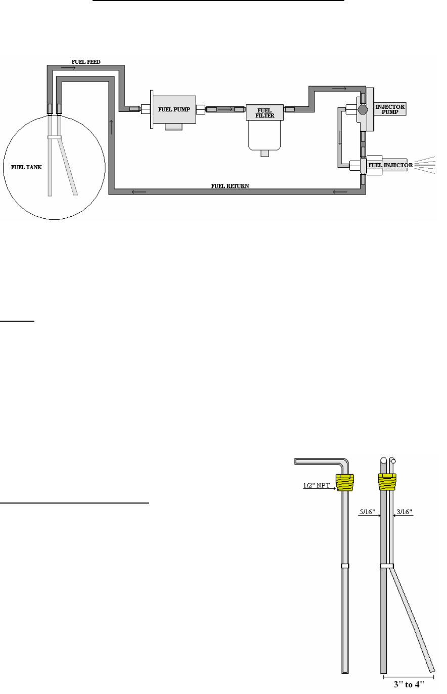
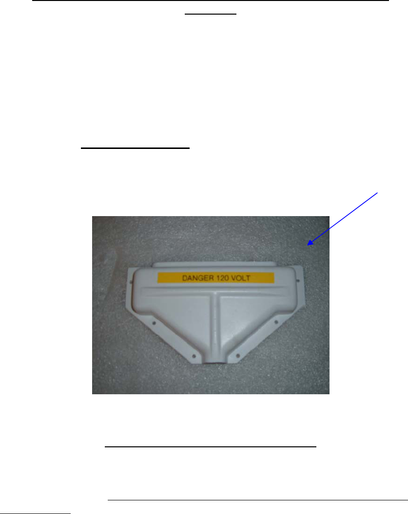
ACCESS FOR ROUTINE MAINTENANCE
A removable service door is provided for easy access to components which require routine maintenance.
An oil drain hole in the base pan is provided for convenient oil draining at scheduled intervals. The oil
level gauge (dip stick) and oil fill port are located just above the oil drain plug on the side of the engine
block. The air filter element is replaced by twisting the end of the air filter housing CCW and pulling
out. Other components such as Fuel Filter and Run Solenoid are easily accessed through the service
door. Electrical controls are conveniently located on the generator end cover.
NOTE: Under normal operation items such as Belts, Hoses and Filters are not covered by Power
Technology Southeast, Inc. Limited Warranty.
24
ENGINE OIL MAINTENANCE
Ambient Temperature Oil Viscosity
Above 25°C (77°F)
SAE 30 or SAE 10W-30
0 to 25°C (32° to 77°F)
SAE 20 or SAE 10W-30
Below 0°C (32°F)
SAE 10 or SAE 10W-30
25
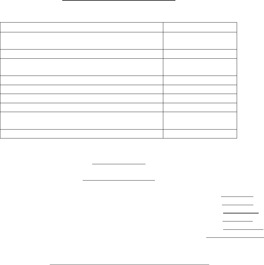
CHECKING ENGINE OIL LEVEL
1. Maintain the engine oil level between “ADD”
mark and “FULL” mark on Oil Level Gauge.
Do not fill crankcase above “FULL” mark.
2. Remove the Oil Filler Cap to add oil, if
necessary. Clean the Oil Filler Cap and replace.
3. The Kubota E-300 is equipped with an Oil
Filter Screen which is attached to the Oil Drain
Plug. Remove the Drain Plug and slide the Filter
Screen completely out. Clean the Filter Screen
with a suitable solvent and air dry. Lubricate the
“O-Ring” and replace unit, tighten securely.
NOTE: Inspect “O-Ring” for damaged, replace
if necessary.
KUBOTA E-300 ENGINE
REFILL CAPACITIES
Crankcase Oil Sump 1.4 US Qts. (1.3L)
LUBRICATING OIL VISCOSITY
RECOMMENDATIONS
The minimum ambient temperature during cold
engine start-up and the maximum ambient
temperature during engine operation determine the
proper SAE viscosity grade of oil.
Refer to the Engine Oil Viscosity Table below
(Minimum Temperature) in order to determine the
required oil viscosity for starting an engine in cold
conditions.
Refer to the Engine Oil Viscosity Table below
(Maximum Temperature) in order to select the oil
viscosity for engine operation at the highest ambient
temperature that is anticipated.
LUBRICATING OIL
SPECIFICATION
Use only good quality
lubricating oil, which meets
the following Specification
API Class
CF
Engine Oil
ENGINE COOLANT MAINTENANCE
26
COOLANT SERVICE LIFE
Coolant Type Service Life
Commercial Heavy-Duty
Coolant/Antifreeze that 3000 Service Hours
Meets “ASTM D5345” or Two Years
Commercial Heavy-Duty
Coolant/Antifreeze that 3000 Service Hours
Meets “ASTM D4985” or One Year
NOTE: Do not use a commercial
coolant/antifreeze that only meets the ASTM
D3306 or D4656 specification. This type of
coolant/antifreeze is made for light duty
automotive applications.
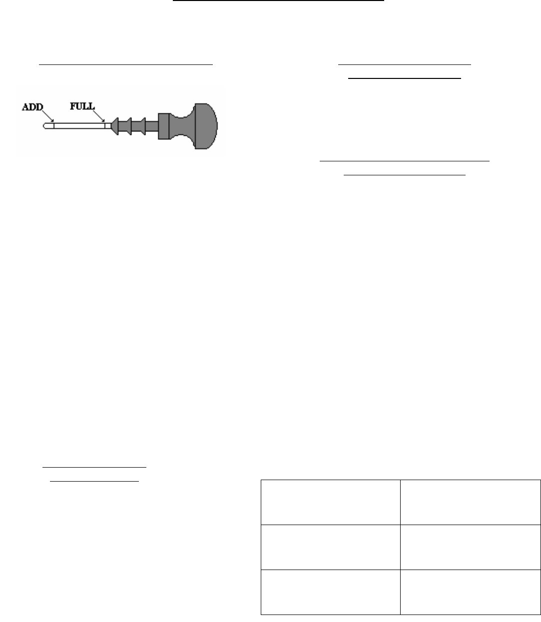
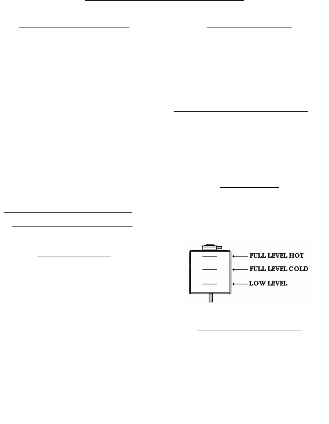
CHECKING RESERVOIR TANK
COOLANT LEVEL
(At a Minimum of 25 Hours of Operation)
Ensure that the coolant level of the radiator
reservoir tank is between the upper limit (FULL)
and the lower limit (LOW).
CLEANING RADIATOR CORE
Visually inspect the core for any obstructions such
as dirt or debris. Use running water to clean
particles from between fins.
IMPORTANT: Never use hard objects to clean
radiator core, damage to core could result.
COOLANT RECOMMENDATIONS
For optimum performance, Power Technology
recommends a 1:1 mixture of water / glycol.
NOTE: Use a mixture that will provide
protection against the lowest ambient
temperature.
NOTE: 100 percent pure glycol will freeze at a
temperature of –23°C (-9°F).
Most conventional heavy-duty coolant /
antifreezes use Ethylene Glycol. Propylene
Glycol may also be used in a 1:1 mixture with
water. Ethylene and Propylene Glycol provide
similar protection against freezing and boiling.
See the tables below.
ETHYLENE GLYCOL
Freeze Boil
Concentration Protection Protection
50 Percent -36°C (-33°F) 106°C (223°F)
60 Percent -51°C (-60°F) 111°C (232°F)
PROPYLENE GLYCOL
Freeze Boil
Concentration Protection Protection
50 Percent -29°C (-20°F) 106°C (223°F)
NOTE: Do not use Propylene Glycol in
concentrations that exceed 50 percent glycol
because of Propylene Glycol’s reduced heat
transfer capability. Use Ethylene Glycol in
conditions that require additional protection
against boiling or freezing.
OPERATING HOURS and SERVICE LOG
THIS SERVICE LOG IS PROVIDED TO HELP YOU KEEP AN ACCUMULATIVE RECORD OF OPERATION HOURS ON YOUR GENERATOR
SET AND THE DATES REQUIRED SERVICES WERE PERFORMED. ENTER TIME TO THE NEAREST HOUR.
OPERATING HOURS SERVICE RECORD
DATE HRs. RUN CUMLATIVE DATE SERVICES
27
SERVICE PROCEDURES
FUEL FILTER / WATER SEPARATOR
The following procedure outlines the steps required for servicing the Racor Fuel Filter / Water
Separator installed on PT-3000 generators. Suggested fuel filter element change at 500 hour intervals
is standard for Racor filters. Operating in adverse conditions or poor quality fuel may require frequent
filter replacements. Follow all safety guidelines when handling fuel and properly discard
contaminated fuel and used element. Avoid injury, shutdown APU and turn OFF Main Switch located
on the APU Control Panel. Allow hot surfaces sufficient time to cool before handling.
1.Open drain valve at the bottom of the See-thru Bowl and drain fuel into a suitable container for
disposal. Open vent plug on filter head to facilitate draining if necessary.
2.Spin off filter element from filter mounting head, separate See-thru Bowl from element and
discard used element.
3.Clean out See-thru Bowl and close drain valve. Lubricate O-Ring and spin onto new filter
element, tighten firmly by hand.
4.Fill filter element and bowl with clean fuel. Lubricate element seal and spin onto filter
mounting head, tighten firmly by hand. Check vent plug and tighten.
5.Turn ON Main Switch located on the APU Control Panel and press the Start Button located on
the Drivers Control Panel.
6.With engine running visually check for fuel leaks. Correct if necessary with engine shutdown
and Main Switch in the OFF position.
NOTE: If it is not convenient to fill the filter bowl with fuel, it is recommended to purge the air
from the filter by following the procedure outlined in the section on “First Time Start-up”.
AIR FILTER ELEMENT
Suggested air filter element change at 500 hours is standard, however operating in adverse
conditions may require frequent filter replacements.
1.Un-screw end cap of air filter housing.
2.Remove used air filter element and discard.
3.Wipe clean the inside of the housing and cap.
4.Install new filter element and replace housing cap.
GENERATOR DRIVE BELT
INFORMATION
PT-3000 utilizes an exclusively engineered drive system between the engine and the generator
end. A combination of custom designed components produces a smooth and reliable drive connection.
The Poly V-Belt is specifically manufactured to Power Technology’s engineering standards and is
backed up with a Life Time Warranty. (See Warranty Page for Details)
Should the Drive Belt ever require service or replacement contact your nearest Dealer or Power
Technology’s Service Dept. at (352)365-2777.
28
POWER TECHNOLOGY SOUTHEAST, INC.
634 STATE ROAD 44
LEESBURG, FL 34748-8103
(352) 365-2777 FAX (352) 787-5545
29
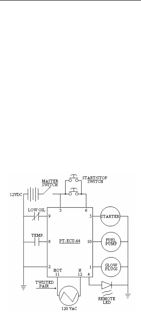
PT-3000 – PT-ECU-64
WIRING SCHEMATIC
RESISTANCE CHART
KW 3 COLOR
MAIN STATOR 0.92 Blue/Brown – Black/White
MAIN ROTOR 4.322 N/A
NOTE: THESE READINGS WILL VARY
DEPENDING ON AMBIENT TEMPERATURE
POWER TECHNOLOGY SOUTHEAST, INC.
634 STATE ROAD 44
LEESBURG, FL 34748-8103
(352) 365-2777 FAX (352) 787-5545
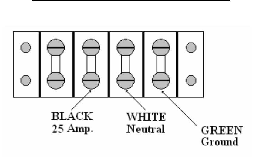
AC ELECTRICAL CIRCUIT FOR 3 KW “S” GENERATORS
120 VOLTS LINE TO NEUTRAL
GENERATOR OUTPUT LEADS
CIRCUIT BREAKER
30 AMP
30
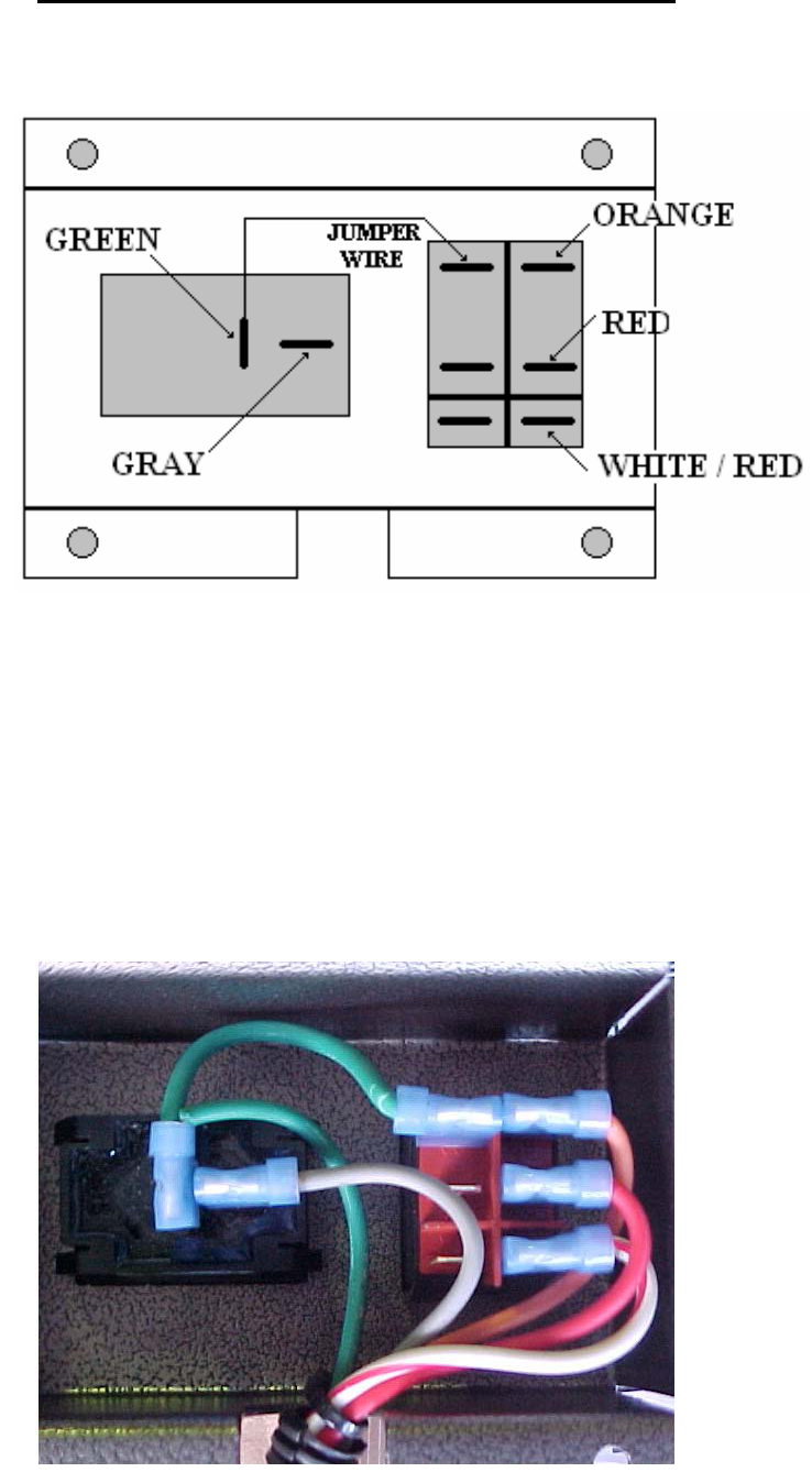
PT-ECU-64 ENGINE CONTROL MODULE
1)Generator Main Switch must be in the ON position.
2)Toggle the Start/Stop Switch to the START position.
3)Glow Plugs will preheat for 8 seconds. LED flashes slowly.
4)Preheating will cease during engine cranking cycle. LED continues flashing.
5)Engine begins an 8 seconds crank cycle, After 4 seconds of cranking the PT-ECU-64 will check for an
AC signal from the generator. If an AC signal is verified the engine will start and the LED will remain
ON during the normal run operation. If the AC signal is not verified the PT-ECU-64 will terminate the
cranking cycle and LED will flash a fault code.
6)Starter disengages immediately after engine run is verified.
7)PT-ECU-64 deactivates the Low Oil Pressure and High Water Temperature Switches for 6
seconds, this will assure oil pressure build-up time. If oil pressure does not build-up the engine will
immediately shut down and go into a fault mode. Likewise for a high temperature situation.
8)If engine will not start on the first attempt the PT-ECU-64 will initiate the start cycle 2 more times
before going into a fault mode. Glow Plugs will preheat for 8 seconds per attempt. Engine will crank
for 8 seconds per attempt.
9)To shut down the engine under normal operations, press the Start/Stop Switch to the STOP position.
10)If a fault occurs turn Generator Main Switch OFF and then ON to reset PT-ECU-64.
Fault Codes: LED Flashes
Failure to start 1
Engine High Water Temperature 2
Low Oil Pressure 3
No AC Signal 4
31
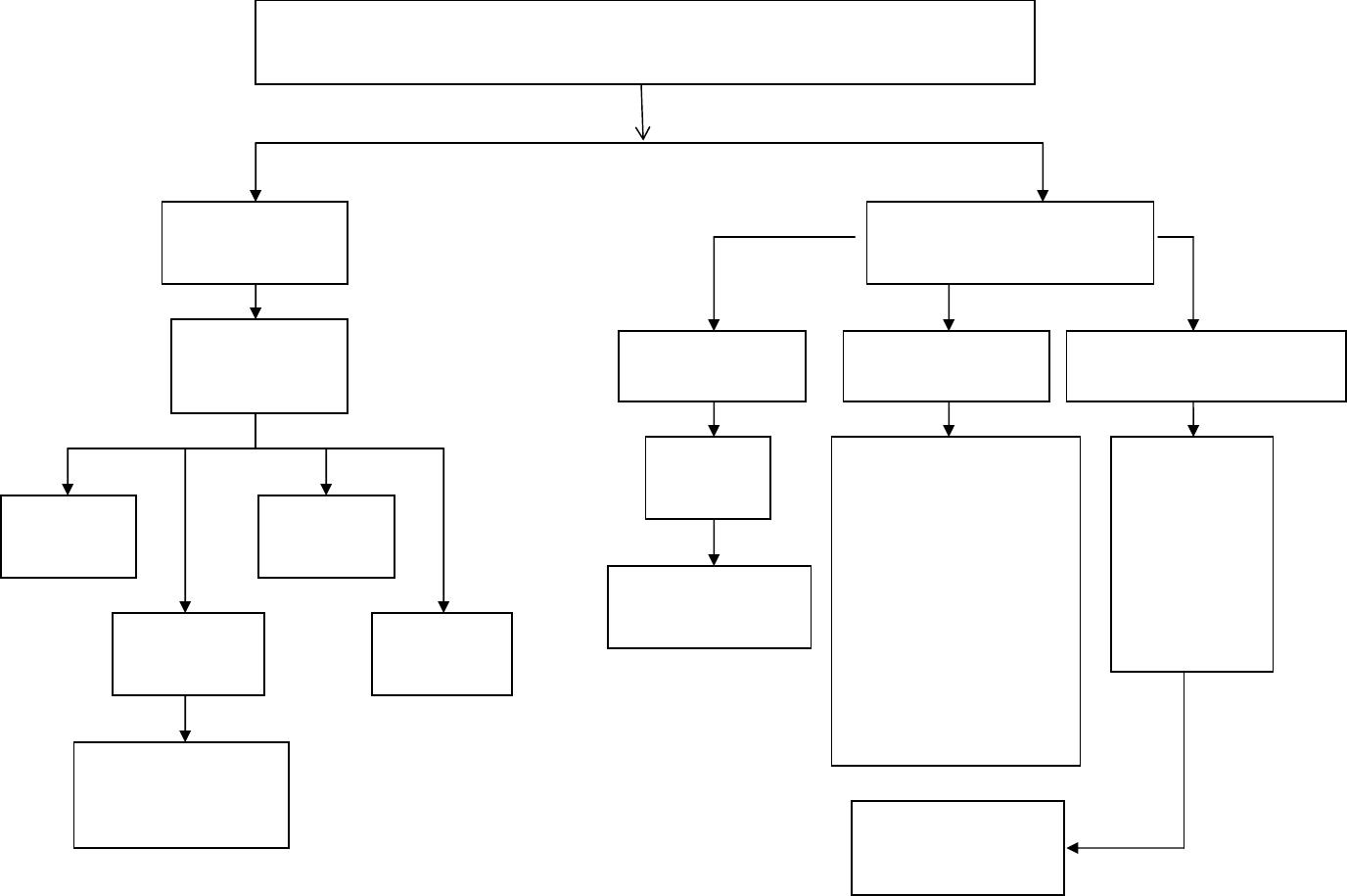
ENGINE WILL NOT START
ENGINE DOES NOT CRANK ENGINE CRANKS ENGINE CRANKS
SLOW
No Exhaust
Smoke
Smoke From
Exhaust
Check Fuel
Solenoid
NO Power
While
Cranking
Check Fuel
Supply
Check Fuel
Pump
Air in
Fuel System
Replace
Solenoid
YES NO
No Power
From
ECU
Check
Glow Plugs
Check Glow
Plug Relay
Check Spark
Arrestor
Muffler for
Clogging
Oil Viscosity
Too Heavy
Main Switch Battery
Dead
Check
Terminals
Turn Switch
On
Start Switch
Starter
Relay
Starter Motor
32
Low Battery
Voltage
33
Engine Cold
Incomplete
Combustion
Over Fueling
Injector
Excessive
Oil Level
BLUE SMOKE
Replace
Fuel Filter
Check
Fuel Level
Air in
Fuel System
Check Safety
Shutdowns
And Fuel Solenoid
Insufficient
Fuel to Engine
No Visible
Exhaust Smoke
Check
Fuel Pump
ENGINE RUNS ROUGH OR SLOW
Excessive Exhaust Smoke
BLACK SMOKE
Dirty Air Filter
Engine Overheated
Engine Overloaded
Clogged Muffler
Over Fueling Injector
High Altitude
GREY/WHITE SMOKE
Glow Plug Circuit
Not Operating
Excessive
Oil Consumption
34
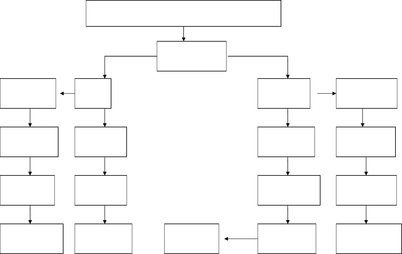
ENGINE TROUBLE SHOOTING
ENGINE STARTS BUT WON’T RUN
Check Flash Code
Indicator at
Start / Sto
p
Switch
CODE 1
CODE 2
Engine High
Water Temp.
Fill System
With 50/50 Mix
Disconnect Wire
Start Engine
Check Coolant
Temp. Switch
Check Coolant
Level/Condition
If “OK”
Replace Switch
If “NOT”
Check Wiring
Check Radiator
Air Flow / Belts
Clean Core
Tighten / Replace
Belts
Failure
To Start
Check Fuel
Filter/Supply
Check Battery
Voltage
Check Circuit
To Actuator
If “OK” Check
Fuel System
If “OK” Replace
Actuator
Bleed Air
From System
Check Fuel
Pump / Circuit
35
ENGINE STARTS BUT WON’T RUN
CONTINUED
ENGINE TROUBLE SHOOTING
Check Flash Code
Indicator at
Start / Sto
p
Switch
CODE 3
CODE 4
No AC Signal
If “Tripped”
Check Generator
Drive Belt
Check Main AC
And Voltage
at Breakers
Low Oil
Pressure
Check Oil
Level/Condition
Disconnect wire
Start Engine
If “OK” Check
Single Pole Oil
Pres. Switch
If “Starts”
Replace Switch
If “Not”
Check Wiring
From Switch to
Terminal 9 at ECU
If “OK”
Replace ECU
Check Terminal
Connections at
11 & 12 on ECU
Check Generator
Wiring and
Ca
p
acitor
Replace Defective
Parts as Needed
If A/C Signal
Present Replace
ECU
ZERO or LOW
VOLTAGE
Check Gen
Ca
p
acitor
Check Main
Breakers are
“
ON
”
Main Coil
Output to
Breakers
Replace
Capacitor
Turn “ON”
Breaker / s
OK
BAD
Wiring To
Panel
Defective
Breaker / s
Check Ohm’s
On Main
Stator Leads
Replace
Stator
Check Rotor
Ohm’s
BAD
OKONOFF
OKBAD
36
37
VOLTAGE TEST
Zero
or
Low Volta
g
e
High
Voltage
Overload
Output
Voltage
OK
Check
Main Breaker / s
On Generator
Replace
Capacitor
Check AMP
Draw
From equipment
Check
Gen End
OVERLOAD CONDITION
Check AMP Draw
C
heck Load
Check Drive Belt
Tension/Condition
38
Engine Problem
See Engine
Troubleshooting
Check
Stator Coil
Resistance
Re
p
lace Stator
Limited Warranty on Power Tech Generators
Power Technology Southeast, Inc. warrants to you, the original purchaser, that each product of our manufacture is free from defects in materials, and workmanship. That
each generator will deliver its rated output as indicated on The Power Technology Nameplate, if properly installed, serviced, and operated under normal conditions in
accordance with Power Technology’s instructions.
THE WARRANTY COVERAGE TERMS:
2 years from date of purchase, or 3000 hours whichever comes first, or 36 months from the date of manufacture. Parts, and labor, including diagnostic labor, removal, and
reinstallation are covered for the first 12 months from date in service or 1000 hours whichever comes first.
Parts and labor are covered only on the following generator and engine parts for 2 years or 3000 hours whichever comes first. Generator Parts: Main Rotor and Main
Stator. Engine Parts: Cylinder Block, cylinder head, crankshaft, camshaft, cylinder head gears, connecting rods, flywheel and flywheel housing, intake and exhaust manifold
(only if flexible connection is used).
3) Stand-by Units are covered for a period of1 year from date of installation, or 1000 hours, or 24 months from the date of manufacture whichever comes first.
4) Replacement Parts are warranted:30 days. (Excluding the following: voltage regulators, fuses, controllers, capacitors, brushes, and switches)
Power Tech will at our option, repair or replace any part covered by this warranty which becomes defective, malfunctions or otherwise fails to conform to this warranty
under normal use and service during the term of this warranty.
WHAT YOU MUST DO TO OBTAIN WARRANTY SERVICE:
In order to obtain warranty repairs you must deliver the product, together with proof of purchase to an authorized Power Tech service facility. In the case of repairs
pertaining to the engine only, you must use an authorized dealer or distributor of that make of engine, to be covered under their warranty. Engines used in the manufacture
of Power Tech products are warranted solely by the engine manufacturer.
PRIOR APPROVAL IS REQUIRED FOR ANY WARRANTY SERVICE
Failure to obtain authorization prior to the repair being performed will result in the claim being denied.
All claims must be submitted within 30 days of the repair. Along with the following: a copy of the original repair order, Power Tech authorization number, Power Tech
serial number, and operation hours shown on the genset mounted hour meter.
THIS WARRANTY DOES NOT COVER THE FOLLOWING:
A. Normal wear items, including but not limited to: turbo-chargers, fuel injector (s), starter, alternator, and electronic components, as well as normal engine and/or generator
wear. A1. Travel time and fuel charges to and from the repair facility or travel time and fuel charges for mobile service. (Except stationary units with a maximum of 2-hours
travel time.) B. Defects, malfunctions or failure resulting from accidents, abuse, misuse, improper servicing, improper installation, improper storage, and lack of
performance of required maintenance service. C. Products which have been subjected to alteration, modification, neglect or unauthorized repairs. D. Troubleshooting,
routine service, tune-ups, replacement of filters, belts, coolant, lubricants, hoses, clamps, exhaust system components, fuel system components, gaskets and/or seals. E.
Electrical items damaged by welding or jump-starting. F. Damage caused by water ingestion or electrolysis. G. Damage caused by ingestion of substances other than clean
filtered air, fuel, or intake water. H. Damage caused by faulty repairs performed by a repair facility not authorized in writing by Power Tech. I. Damage caused by operation
with improper fuel or at speeds, loads, conditions, modifications, or installation contrary to published specifications or recommendations. J. Original installation charges and
startup costs. K. Removal and re-installation charges of more than 1-hour labor for outside units, 2-hours for compartment mounted units, and 3-hours for below deck
marine units. Customer is responsible for additional labor/charges due to difficult access, removal or installation. L. Starting batteries and labor or charges related to battery
service. M. Loss of revenue or the rental of equipment due to down time. N. Generator repairs made within the warranty period other than by an authorized Power Tech
service dealer without prior written approval from Power Tech warranty department. O. Damage caused by negligent maintenance such as but not limited to: Failure to
provide the specified type and quantity of lubricating oil, cooling air flow, and proper coolant mixture and level. Failure to provide adequate air intake/or maintenance of the
air intake system. Failure to provide scheduled maintenance as prescribed in supplied manuals. P. Engine fluids such as fuel, oil or coolant/antifreeze. Q. Shop supplies such
as adhesives, cleaning agents, rags, paint, or other miscellaneous supplies. R. Use of other than factory supplied or approved repair parts or procedures. Replacement of a
failed Power Tech component with a non-Power Tech component voids the Power Tech warranty on that component and any and all failures related to that component. S.
Fuel injection pumps repaired by anyone other than the factory authorized dealer or distributor of that engine. T. Expenses incurred investigating performance complaints
unless defective Power Tech materials or workmanship are discovered. U. Generator sets used in rental applications. V. Cleaning, service, or repair of generator sets the
have not been kept free of dirt, debris, or other items that prevent the unit from being able to operate properly. W. Any generator set not application approved. X. Loss of
excitation due to prolonged storage. Y. Any damage attributed to low battery monitoring or automatic generator starting systems. Z. Optional accessories are warranted
solely by the manufacturer of that item including but not limited to the following item: Block heaters, oil pan heaters, electric cooling fans, air-bag isolators, compartment
For your nearest Power Tech authorized service center, on the World Wide Web at: http://www.powertech-gen.com/parts_service.php
Call 1-352-365-2777 or write to Power Tech Warranty Department, P.O. Box 490133 Leesburg, FL 34749 USA.
Power Tech must be notified in writing within five (5) business days of any product failure.
General Conditions:
This Warranty is the sole property of the original owner /user.
A transfer of ownership shall terminate this Warranty.
This Warranty is only valid within the contiguous United States and Canada.
Warranty coverage is available outside the U.S. and Canada; please speak to a factory representative for those details.
This Warranty does not cover any products or parts not purchased from Power Technology.
Power Technology reserves the right to make design improvements and model changes without any obligation to change units or parts previously manufactured.
Warranty registration card must be completed and mailed to Power Tech at the above address to validate the Warranty.
This is the only express warranty on Power Tech products
No person, agent, or dealer is authorized to give any Warranties on behalf of Power Technology Southeast, Inc., and not to assume for Power Technology Southeast,
Inc. any other liability in connection with any of its products unless made in writing and signed by an officer of Power Technology Southeast, Inc.
LIMITATIONS ON OUR RESPONSIBILITY WITH RESPECT TO PRODUCTS PURCHASED AND USED FOR PERSONAL, FAMILY OR HOUSEHOLD USE:
Our responsibility is to repair or replace defective parts as stated above. We will not be responsible for any other expenses, losses or inconvenience which you may
Sustain as a result of the purchase, use, malfunction or defective condition of our products. ANY IMPLIED WARRANTIES, INCLUDING WARRANTIES OF
MERCHANTABILITY OR FITNESS FOR A PARTICULAR PURPOSE SHALL BE LIMITED IN DURATION TO THE PERIOD SET FORTH ABOVE.
Some states do not allow limitations on how long an implied Warranty lasts or the exclusion or limitation of incidental or consequential damages, so the above
Limitations or exclusions may not apply to you. This Warranty gives you specific legal rights and you may have other rights which vary from state to state.
This Warranty is in lieu of all other Warranties, expressed or implied and of any other obligations or liability on our part.
Our responsibility for any and all losses and IN NO EVENT WILL WE BE LIABLE FOR LOSS OF USE, LOSS OF PROFITS, INCONVIENCE, COMMERCIAL LOSS
OR OTHER INCIDENTIAL OR CONSEQUENTIAL DAMAGES WHATSOEVER.
Nieuw aggregaat pt2000 start perfect maar komt geen stroom uit half jaar oud nog nooit gebruikt. Handleiding zoek geraakt. Zit er misschien een zekering?
Gesteld op 10-7-2024 om 17:01
Gebruikershandleiding.com neemt misbruik van zijn services uitermate serieus. U kunt hieronder aangeven waarom deze vraag ongepast is. Wij controleren de vraag en zonodig wordt deze verwijderd.
Product:
Spelregels forum
Om tot zinvolle vragen te komen hanteren wij de volgende spelregels:
lees eerst de handleiding door;
controleer of uw vraag al eerder door iemand anders is gesteld;
probeer uw vraag zo duidelijk mogelijk te stellen;
heeft u een probleem en al geprobeerd om dit op te lossen, vermeld dit erbij aub;
heeft u een oplossing gekregen van een bezoeker dan horen wij dat graag in dit forum;
wilt u een reactie geven op een vraag of antwoord, gebruik dan niet dit formulier maar klik op de knop 'reageer op deze vraag';
uw vraag wordt direct op de website gezet; vermijd daarom persoonlijke gegevens in te vullen;
Belangrijk! Als er een antwoord wordt gegeven op uw vraag, dan is het voor de gever van het antwoord nuttig om te weten als u er wel (of niet) mee geholpen bent! Wij vragen u dus ook te reageren op een antwoord.
Belangrijk! Antwoorden worden ook per e-mail naar abonnees gestuurd. Laat uw emailadres achter op deze site, zodat u op de hoogte blijft. U krijgt dan ook andere vragen en antwoorden te zien.
Abonneren
Abonneer u voor het ontvangen van emails voor uw PowerTech PT-3000 bij:
nieuwe vragen en antwoorden
nieuwe handleidingen
U ontvangt een email met instructies om u voor één of beide opties in te schrijven.
Ontvang uw handleiding per email
Vul uw emailadres in en ontvang de handleiding van PowerTech PT-3000 in de taal/talen: Engels als bijlage per email.
De handleiding is 3,09 mb groot.
U ontvangt de handleiding per email binnen enkele minuten. Als u geen email heeft ontvangen, dan heeft u waarschijnlijk een verkeerd emailadres ingevuld of is uw mailbox te vol. Daarnaast kan het zijn dat uw internetprovider een maximum heeft aan de grootte per email. Omdat hier een handleiding wordt meegestuurd, kan het voorkomen dat de email groter is dan toegestaan bij uw provider.
Stel vragen via chat aan uw handleiding
Stel uw vraag over deze PDF
Uw handleiding is per email verstuurd. Controleer uw email
Als u niet binnen een kwartier uw email met handleiding ontvangen heeft, kan het zijn dat u een verkeerd emailadres heeft ingevuld of dat uw emailprovider een maximum grootte per email heeft ingesteld die kleiner is dan de grootte van de handleiding.
Er is een email naar u verstuurd om uw inschrijving definitief te maken.
Controleer uw email en volg de aanwijzingen op om uw inschrijving definitief te maken
U heeft geen emailadres opgegeven
Als u de handleiding per email wilt ontvangen, vul dan een geldig emailadres in.
Uw vraag is op deze pagina toegevoegd
Wilt u een email ontvangen bij een antwoord en/of nieuwe vragen? Vul dan hier uw emailadres in.