751763
25
Verklein
Vergroot
Pagina terug
1/26
Pagina verder
Generating Power to the World
Page 1 of 26
PTI-15/20SI-T4F Operators Manual
Power Technology Southeast
634 State Road 44
Leesburg, FL 34748-8103
Phone: (352)-365-2777
Fax: (352) 787-5545
Generating Power to the World
Page 2 of 26
PTI-15/20SI-T4F Operators Manual
Table of Contents
FORWARD .................................................................................................................................................... 4
TO OUR CUSTOMERS ................................................................................................................................ 4
Limited Warranty on Power Tech Generators ............................................................................................... 5
SAFE OPERATION ....................................................................................................................................... 7
Proposition 65 Warning ......................................................................................................................... 7
CONDUCTING SAFETY CHECKS AND MAINTENANCE ......................................................................... 12
Operating the Generator ............................................................................................................................. 13
Daily Pre Operational Checks ................................................................................................................. 13
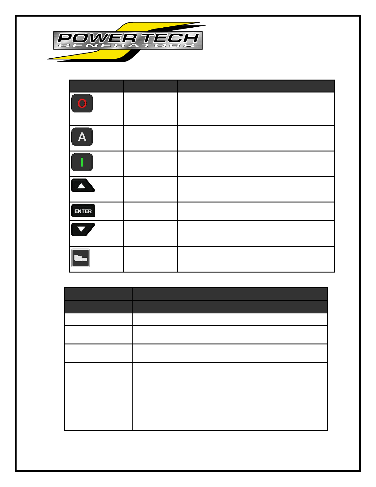
Using the PTG Series Controller ............................................................................................................. 13
Front Panel Items ................................................................................................................................ 14
Using the Menu System ...................................................................................................................... 14
Modes, Starting and Stopping Methods .............................................................................................. 15
Engine Specifications .................................................................................................................................. 16
Engine Maintenance Schedule ................................................................................................................... 17
Engine Oil Maintenance .............................................................................................................................. 18
Lubricating Oil Specifications .................................................................................................................. 18
LUBRICATING OIL VISCOSITY ............................................................................................................. 18
RECOMMENDATIONS ........................................................................................................................... 18
COOLANT RECOMMENDATIONS ............................................................................................................ 19
CHECKING RADIATOR COOLANT LEVEL ........................................................................................... 19
COOLANT SERVICE LIFE ..................................................................................................................... 20
CHECKING RESERVOIR TANK ............................................................................................................ 20
COOLANT LEVEL ................................................................................................................................... 20
CLEANING RADIATOR CORE ................................................................................................................... 20
OPERATING HOURS and SERVICE LOG ................................................................................................ 21
GENERATOR ASSEMBLY INFORMATION ............................................................................................... 22
EXCITER TYPE GENERATOR .............................................................................................................. 22
ELECTRONIC VOLTAGE REGULATION .............................................................................................. 22
VOLTAGE CONNECTION ...................................................................................................................... 22
Generating Power to the World
Page 3 of 26
PTI-15/20SI-T4F Operators Manual
EXCITER FIELD COIL VOLTAGE SOURCE ......................................................................................... 23
ROTATING FIELD ASSEMBLY (ROTOR) ............................................................................................. 23
CORE ASSEMBLY ................................................................................................................................. 23
FIELD COIL ............................................................................................................................................. 23
BALANCE................................................................................................................................................ 23
BEARING ................................................................................................................................................ 24
STATOR ASSEMBLY ............................................................................................................................. 24
TROUBLESHOOTING ................................................................................................................................ 25
TROUBLE ............................................................................................................................................... 26
POSSIBLE CAUSE ................................................................................................................................. 26
SUGGESTED ACTION ........................................................................................................................... 26
Generating Power to the World
Page 4 of 26
PTI-15/20SI-T4F Operators Manual
FORWARD
You are now the proud owner of a Power Technology Southeast generator set, powered by an industrial
Isuzu diesel engine. This generator set is a Part of Power Tech`s Tier 4 Final Generator product line. It is
the engineered to the utmost quality standards and manufactured in a strict quality control environment
and will assure you a long, satisfactory service. To have the best performance from your Power Tech
Generator, please fully read and understand this manual. This manual is written to better provide “YOU”
with the information you need to operate and maintenance your generator. This manual was up to date at
time of printing/downloading, there may be changes not reflected in your manual. If there is any questions
please contact Power Technology’s customer service dept.
TO OUR CUSTOMERS
Thank you for your purchase of a Power Technology Generator. In the event you experience a problem
with your generator please contact the sales dealer, one of our authorized service centers or Power
Technology’s Customer Service Department directly at 1-800-760-0027 from 8:00 a.m. to 5:00 p.m. EST.
Please have the generator model and serial numbers available when you call. This will help expedite
service and parts to you. Parts may be obtained directly through Power Technology and shipped the
same day if ordered by 3:00 p.m. EST.
Parts may be ordered any time at
WWW.POWERTECHPARTS.COM
To find a list of our dealers, scan
the QR code below
Generating Power to the World
Page 5 of 26
PTI-15/20SI-T4F Operators Manual
Limited Warranty on Power Tech Generators
Power Technology Southeast, Inc. warrants to you, the original purchaser, that each product of our manufacture is free from defects in materials,
and workmanship. That each generator will deliver its rated output as indicated on The Power Technology Nameplate, if properly installed,
serviced, and operated under normal conditions in accordance with Power Technology’s instructions.
THE WARRANTY COVERAGE TERMS:
2 years from date of purchase, or 3000 hours whichever comes first, or 36 months from the date of manufacture. Parts, and labor, including
diagnostic labor, removal, and reinstallation are covered for the first 12 months from date in service or 1000 hours whichever comes first.
Parts and labor are covered only on the following generator and engine parts for 2 years or 3000 hours whichever comes first. Generator Parts:
Main Rotor and Main Stator. Engine Parts: Cylinder Block, cylinder head, crankshaft, camshaft, cylinder head gears, connecting rods,
flywheel and flywheel housing, intake and exhaust manifold (only if flexible connection is used).
3) Stand-by Units are covered for a period of 1 year from date of installation, or 1000 hours, or 24 months from the date of manufacture
whichever comes first.
4) Replacement Parts are warranted: 30 days. (Excluding the following: voltage regulators, fuses, controllers, capacitors, brushes, and
switches)
____________________________________________________________________________________________________________
____________________ WHAT POWER TECHNOLOGY WILL DO:
Power Tech will at our option, repair or replace any part covered by this warranty which becomes defective, malfunctions or otherwise fails to
conform to this warranty under normal use and service during the term of this warranty.
WHAT YOU MUST DO TO OBTAIN WARRANTY SERVICE:
In order to obtain warranty repairs you must deliver the product, together with proof of purchase to an authorized Power Tech service facility. In
the case of repairs pertaining to the engine only, you must use an authorized dealer or distributor of that make of engine, to be covered under their
warranty. Engines used in the manufacture of Power Tech products are warranted solely by the engine manufacturer.
PRIOR APPROVAL IS REQUIRED FOR ANY WARRANTY SERVICE
Failure to obtain authorization prior to the repair being performed will result in the claim being denied.
All claims must be submitted within 30 days of the repair. Along with the following: a copy of the original repair order, Power Tech authorization
number, Power Tech serial number, and operation hours shown on the genset mounted hour meter.
THIS WARRANTY DOES NOT COVER THE FOLLOWING:
A. Normal wear items, including but not limited to: turbo-chargers, fuel injector (s), starter, alternator, and electronic components, as well as
normal engine and/or generator wear. A1. Travel time and fuel charges to and from the repair facility or travel time and fuel charges for mobile
service. (Except stationary units with a maximum of 2-hours travel time.) B. Defects, malfunctions or failure resulting from accidents, abuse,
misuse, improper servicing, improper installation, improper storage, and lack of performance of required maintenance service. C. Products which
have been subjected to alteration, modification, neglect or unauthorized repairs. D. Troubleshooting, routine service, tune-ups, replacement of
filters, belts, coolant, lubricants, hoses, clamps, exhaust system components, fuel system components, gaskets and/or seals. E. Electrical items
damaged by welding or jump-starting. F. Damage caused by water ingestion or electrolysis. G. Damage caused by ingestion of substances other
than clean filtered air, fuel, or intake water. H. Damage caused by faulty repairs performed by a repair facility not authorized in writing by Power
Tech. I. Damage caused by operation with improper fuel or at speeds, loads, conditions, modifications, or installation contrary to published
specifications or recommendations. J. Original installation charges and startup costs. K. Removal and re-installation charges of more than 1-hour
labor for outside units, 2-hours for compartment mounted units, and 3-hours for below deck marine units. Customer is responsible for additional
labor/charges due to difficult access, removal or installation. L. Starting batteries and labor or charges related to battery service. M. Loss of
revenue or the rental of equipment due to down time. N. Generator repairs made within the warranty period other than by an authorized Power
Tech service dealer without prior written approval from Power Tech warranty department. O. Damage caused by negligent maintenance such as
but not limited to: Failure to provide the specified type and quantity of lubricating oil, cooling air flow, and proper coolant mixture and level.
Failure to provide adequate air intake/or maintenance of the air intake system. Failure to provide scheduled maintenance as prescribed in supplied
manuals. P. Engine fluids such as fuel, oil or coolant/antifreeze. Q. Shop supplies such as adhesives, cleaning agents, rags, paint, or other
miscellaneous supplies. R. Use of other than factory supplied or approved repair parts or procedures. Replacement of a failed Power Tech
component with a non-Power Tech component voids the Power Tech warranty on that component and any and all failures related to that
component. S. Fuel injection pumps repaired by anyone other than the factory authorized dealer or distributor of that engine. T. Expenses
incurred investigating performance complaints unless defective Power Tech materials or workmanship are discovered. U. Generator sets used in
rental applications. V. Cleaning, service, or repair of generator sets the have not been kept free of dirt, debris, or other items that prevent the unit
from being able to operate properly. W. Any generator set not application approved. X. Loss of excitation due to prolonged storage. Y. Any
damage attributed to low battery monitoring or automatic generator starting systems. Z. Optional accessories are warranted solely by the
manufacturer of that item including but not limited to the following item: Block heaters, oil pan heaters, electric cooling fans, air-bag isolators,
compartment heaters, fuel tanks, trailers, battery chargers, battery monitors.
To obtain warranty service: For your nearest Power Tech authorized service center, on the World Wide Web at: http://www.powertech-
gen.com/parts_service.php Call 1-352-365-2777 or write to Power Tech Warranty Department, P.O. Box 490133 Leesburg, FL 34749 USA.
Power Tech must be notified in writing within five (5) business days of
any product failure. General Conditions:
This Warranty is the sole property of the original owner /user.
A transfer of ownership shall terminate this Warranty.
Generating Power to the World
Page 6 of 26
PTI-15/20SI-T4F Operators Manual
This Warranty is only valid within the contiguous United States and Canada.
Warranty coverage is available outside the U.S. and Canada; please speak to a factory representative for those details.
This Warranty does not cover any products or parts not purchased from Power Technology.
Power Technology reserves the right to make design improvements and model changes without any obligation to change units or parts
previously manufactured. Warranty registration card must be completed and mailed to Power Tech at the above address to validate the
Warranty.
This is the only express warranty on Power Tech products
No person, agent, or dealer is authorized to give any Warranties on behalf of Power Technology Southeast, Inc., and not to assume for Power
Technology Southeast, Inc. any other liability in connection with any of its products unless made in writing and signed by an officer of Power
Technology Southeast, Inc.
LIMITATIONS ON OUR RESPONSIBILITY WITH RESPECT TO PRODUCTS PURCHASED AND USED FOR PERSONAL, FAMILY OR
HOUSEHOLD USE:
Generating Power to the World
Page 7 of 26
PTI-15/20SI-T4F Operators Manual
SAFE OPERATION
Observe Safety Instructions
Wear Safety Clothing
Check Before Operating the Engine
Keep Area around the engine clean
Safe Handling of Fuel and Lubricants
Exhaust Gases and Fire Prevention
Escaping Fluids
Cautions against Burns and Battery Explosion
Keep Hands and Body Away From Rotating Parts
Anti-Freeze and Disposal of Fluids
Conducting Safety Checks and Maintenance
These symbols, the industry’s “Safety Alert Symbol”, is used throughout this manual and on labels
attached the machine itself. It warns of the potential for personal injury. It is essential that you carefully
read the instructions and safety regulations before you attempt to assemble or use this unit.
WARNING: Indicates a potentially hazardous situation, which may possibly result in serious
injury or possible death.
CAUTION: Indicates a potentially hazardous situation, which may possibly result in minor injury.
IMPORTANT: Indicates that equipment or property damage may result if instructions are not followed.
NOTE: Indicates helpful information.
Cautious operation is your best insurance against an accident. Read and understand this section carefully
before operating the engine. All operators, no matter how knowledgeable they may be, should read this
and other related manuals before operating the engine or any equipment attached to it. It is the owner’s
CALIFORNIA
Proposition 65 Warning
Diesel Engine Exhaust and
some of its constituents are
known by the State of
California to cause Cancer,
Birth Defects and Other
Reproductive harm.
Generating Power to the World
Page 8 of 26
PTI-15/20SI-T4F Operators Manual
responsibility to instruct all operators in safe operation. Be sure to observe the following for safe
operation.
OBSERVE SAFETY INSTRUCTIONS
Read, understand and follow this “OPERATORS MANUAL”
and “LABELS ON THE ENGINE” before starting and
operating.
Learn how to operate and work safely. Know your equipment
and its limitations. Always keep the generator in good
condition.
Before allowing other people to use your engine, explain how
to operate and have them read this manual before operation.
DO NOT modify the engine. UNAUTHORIZED
MODIFICATIONS to the engine may impair the function
and/or safety and affect engine life.
WEAR SAFETY CLOTHING
DO NOT wear loose, torn or bulky clothing around machinery.
Entanglement in rotating parts, controls or projections may cause
persona injury.
Use additional safety items, e.g. hardhat, eye protection, gloves,
etc., as appropriate or required.
DO NOT operate machinery or equipment while under the influence
of alcohol, medication, or other drugs, or while fatigued.
DO NOT wear radio or music headphones while operating engine.
CHECK BEFORE OPERATING THE ENGINE
If the engine is malfunctioning DO NOT operate until repairs
are made.
Be sure all guards and shields are in place before operating
the engine. Replace any that are damaged or missing.
Check to see that the area around the engine is clear of
foreign objects before starting.
Always keep the engine at least 3 feet (1 meter) away from
buildings or other facilities.
DO NOT allow children or livestock to approach the machine
while in operation.
DO NOT start the engine by shorting across starter terminals.
Generating Power to the World
Page 9 of 26
PTI-15/20SI-T4F Operators Manual
KEEP AREA AROUND THE ENGINE CLEAN
Be sure to stop the engine before cleaning.
Keep the engine clean and free of accumulated dirt, grease and
trash.
DO NOT stop the engine without idling; Temperatures around the
genset rises suddenly. Keep the genset idling for about 5 minutes
before stopping?
SAFE HANDLING OF FUEL AND LUBRICANTS
Always stop the engine before refueling or lubricating.
DO NOT smoke or allow flames or sparks in your working area. Fuel
is extremely flammable and explosive. Never store flammable liquids
in the engine compartment.
Refuel at a well-ventilated and open place. If fuel or lubricants spill, clean up immediately and
properly dispose of.
DO NOT mix gasoline or alcohol with diesel fuel. The mixture can cause a fire.
EXHAUST GASES AND FIRE PREVENTION
Engine exhaust fumes can be very harmful if allowed to
accumulate. Be sure to run the engine in a well-ventilated area
where there are no people or livestock nearby.
The exhaust gas from the muffler is very hot. To prevent a fire,
do not expose dry grass, oil or any other combustible
materials to exhaust gas. Keep the engine and mufflers clean
all the time.
To avoid a fire, be alert for leaks of flammables from hoses
and lines. Be sure to check for leaks from hoses and pipes,
such as fuel and hydraulic by following the maintenance check
list.
To avoid a fire, do not short across power cables and wires.
Check to see that all power cables and wires are in good condition. Keep all power connections
clean. Bare wire or frayed insulation can cause a dangerous electrical shock and personal injury.
Generating Power to the World
Page 10 of 26
PTI-15/20SI-T4F Operators Manual
Escaping fluids
Relieve all pressure in the air, oil and cooling systems
before any lines, fittings or related items are removed or
disconnected.
Be alert for possible pressure release when disconnecting
any device from a system that is pressurized. DO NOT
check for pressure leaks with your hands. High-pressure
oil or fuel can cause personal injury.
Escaping hydraulic fluid under pressure has sufficient
force to penetrate skin causing serious personal injury.
Fluid escaping from pinholes may be invisible. Use a
piece of cardboard or wood to search for suspected
leaks: do not use hands and body. Use safety goggles or
other eye protection when checking for leaks.
If injured by escaping fluid, see a medical doctor
immediately. This fluid can produce gangrene or severe allergic reaction.
CAUTIONS AGAINST BURNS AND BATTERY EXPLOSION
To avoid burns, be alert for hot components during operation and
after the engine has been shut off. Such as the muffler, muffler
cover, radiator, piping, engine body, coolants, engine oil, etc.
DO NOT remove the radiator cap while the engine is running or
immediately after stopping. Wait approximately ten minutes for the
radiator to cool before removing the cap.
Be sure the radiator drain valve / petcock and hose clamps are
tightened. Check radiator pressure cap and oil fill cap before
operating the engine.
The battery presents an explosive hazard. When the battery is
being activated, hydrogen and oxygen gases are extremely
explosive.
Keep sparks and open flames away from the battery, especially
during charging. DO NOT strike a match near the battery.
DO NOT check a batteries charge by placing a metal object across
the terminals. Use a voltmeter or hydrometer.
DO NOT charge a battery if frozen, it may possibly explode. Frozen
batteries must be warm up to at least 61°F (16°C) before charging.
KEEP HANDS AND BODY AWAY FROM ROTATING PARTS
Keep your hands and body away from all rotating parts, such as
cooling fan, v-belts, pulleys and flywheel. Contact with these rotating
parts can cause serious personal injury.
Be sure to stop the engine before adjusting belt tension or checking
the cooling fan.
DO NOT run the engine without safety guards installed. Be sure the
safety guards are properly aligned and securely fastened before
operating the engine.
Generating Power to the World
Page 11 of 26
PTI-15/20SI-T4F Operators Manual
ANTI-FREEZE AND DISPOSAL OF FLUIDS
Anti-freeze contains toxic chemicals. Wear rubber gloves when handling anti-freeze. In case of
contact with skin, wash immediately to avoid personal injury.
DO NOT mix different types of Anti-freeze. The mixture can produce a chemical reaction resulting
in the formation of harmful substances. Only use anti-freeze that is recommended and approved
by Engine Manufacturer.
Be mindful of the environment. Before draining any fluids, be prepared to dispose of them in a
manner consistent with environmental protection regulations in your location.
When draining fluids from the engine, use appropriate containers to hold the different fluids, do
not mix fuel, oil or coolant together. Dispose of spent filter cartridges and batteries properly.
DO NOT pollute the soil, or any water source. Never pour fluids down a drain.
Generating Power to the World
Page 12 of 26
PTI-15/20SI-T4F Operators Manual
CONDUCTING SAFETY CHECKS AND MAINTENANCE
When performing safety checks or engine service, be sure the engine is level and well supported.
Use approved stands designed for this type of service.
DO NOT service an engine that is only supported by a lift jack or hoist.
Detach the battery from the engine before conducting service.
To avoid sparks from an accidental short circuit always disconnect the 12V DC power at the
battery.
Be sure to stop the engine and remove the key when conducting daily and periodic maintenance,
servicing and cleaning.
Check or conduct maintenance after the engine, radiator, muffler, or muffler cover has cooled off
completely.
Always use the appropriate tools and jig-fixture when performing any service work. Be sure to
understand and follow the instructions included with these tools.
Use ONLY correct engine barring techniques for manually rotating the engine. DO NOT attempt
to rotate the engine by pulling or prying on the cooling fan and V-belt. Serious personal injury or
damage to the cooling fan may occur.
Replace fuel hoses and hose clamps every 2 years or earlier whether they are damaged or not.
They are made of rubber and are aged gradually.
When service is performed with two or more people present, take care to perform all work safely.
Be aware of their location especially when starting the engine.
Keep a first aid kit and fire extinguisher handy at all times.
Generating Power to the World
Page 13 of 26
PTI-15/20SI-T4F Operators Manual
Operating the Generator
Daily Pre Operational Checks
Check the engine oil level to be appropriate level
Check for tightness of battery cables/terminals.
Check battery terminals for absence of corrosion
Check coolant level for proper Fill (add if necessary)
Check for absence of water in fuel (drain if necessary)
Check for absence of DTC or failures
Check for absence of excessive fan belt looseness
Using the PTG Series Controller
The LCD display is the primary source of information of the controller. The LCD
allows you to view/change settings and monitor the status of sensors and other
engine parameters.
* NOTE: The genset mounted controller must be in “AUTO” mode in order to enable the remote
panel functionality.
Generating Power to the World
Page 14 of 26
PTI-15/20SI-T4F Operators Manual
Front Panel Items
Item
Name
Description
Off Button
Used for turning off the engine or exiting out of Auto
mode. This is not intended to function as an Emergency
Stop as there are conditions in which it will not
shutdown the engine.
Auto Button
Used for placing the controller into Auto mode. Once in
Auto the controller waits for a start command to be
received.
Run Button
Used to start the engine manually. Must use the Off
button to shut down the engine if started from front
panel.
Up Button
Used for moving around in the menu, changing a
settings value, or changing the currently displayed
parameter page.
Enter Button
Used for entering the menu system, accepting settings,
or locking the LCD screen when viewing parameters.
Down Button
Used for moving around in the menu, changing a
settings value, or changing the currently displayed
parameter page.
Generator LED
Green = Engine running with no issues
Amber = Engine running with warnings
Red = Engine shutdown on failure
Using the Menu System
Task
Entering Menu
Navigating Menu
Scroll Parameters
Lock Screen
Events History
Generating Power to the World
Page 15 of 26
PTI-15/20SI-T4F Operators Manual
Modes, Starting and Stopping Methods
The following table describes the different operating modes of the controller:
Mode / State
Description
OFF
When in the OFF mode, the engine cannot be remotely started.
Auto
When in the Auto mode, the engine waits to receive a start command.
Running
When engine is Running, the controller monitors engine parameters
and waits to receive a stop command.
Failure
When a failure occurs, the controller shuts down the engine and
displays reason for failure. The unit must be reset using the front panel
OFF button with the exception of Modbus.
Menu
When in the menu you can change settings and view the events
history.
Generating Power to the World
Page 16 of 26
PTI-15/20SI-T4F Operators Manual
Engine Specifications
Engine Make:
Isuzu
Engine Model:
4LE2T
EPA Tier
Tier 4 Final
KWM @1800rpm
30
Oil type
SAE 10W-40 (API Class)
Oil capacity
8.4 Qts (8L)
Cooling System Capacity
11.25 Qts (10.6L)
Air Filter P/N
04FA2768
Primary Fuel filter P/N
08FF4LE-P
Secondary Fuel Filter P/N
08FF4LE-S
OIL filter P/N 15-20 KW
01FO4LE
Generating Power to the World
Page 17 of 26
PTI-15/20SI-T4F Operators Manual
Engine Maintenance Schedule
NOTE: Under normal operation, items such as belts, hoses and filters are not
covered By Power Technology Southeast Limited Warranty.
*Engine Oil must be changed after the first 50 hours of service then in 150 hour
intervals after the first 50 hours.
*Filter replacement intervals vary depending on quality of air, fuel, etc. Your Generator
is Equipped with filter minder capability to display on LCD screen when air/ fuel filters
need to be changed.
Maintenance Service Item
See
notes
Daily
150 Hour
Interval
500 Hour
Interval
1000 Hour
Interval
Remarks
Engine Oil Level
deterioration & Leakage
x
Engine Oil Change
x
x
Or Once a
Year
Oil Filter Change
x
Or Once a
Year
Coolant Level
x
Coolant Leakage
x
Coolant Change
x
Or Once a
Year
Fuel Level
x
Fuel Leakage
x
Water in Fuel
x
x
Primary Fuel filter
Replacement
x
x
Or Once a
Year
Secondary Fuel Filter
Replacement
x
x
Or Once a
Year
Air filter Replacement
x
x
Or Once a
Year
Damaged, Worn or loose
belts
x
Or Two Year
Intervals
Replace Fuel Lines/Hoses
x
Or Two Year
Intervals
Radiator Hoses and
Clamps
x
Or Once a
Year
Abnormal Engine Noise
x
Exhausts Gas Condition
x
Generating Power to the World
Page 18 of 26
PTI-15/20SI-T4F Operators Manual
Engine Oil Maintenance
Checking the Engine Oil Level
1) Maintain Proper Oil Level
Between “ADD”(Y) and “Full” (X) on
the oil level Gauge. DO NOT fill
above “Full” mark as catastrophic
engine damage will occur.
2) Remove the oil filler cap and add oil if necessary. Clean the oil filler cap
with a clean rag or towel. Reinstall the oil filler cap by hand.
Lubricating Oil Specifications
Use only good quality Lubricating Oil, which meets the following Specifications.
API Class
CJ-4
Engine Oil
LUBRICATING OIL VISCOSITY
RECOMMENDATIONS
The minimum ambient temperature during cold engine start-up and the maximum ambient temperature
during engine operation determine the proper SAE viscosity grade of oil.
Refer to the Engine Oil Viscosity Table below (Lowest Ambient Temperature) in order to determine the
required oil viscosity for starting an engine in cold conditions.
Refer to the Engine Oil Viscosity Table below in order to select the oil viscosity for engine operation at the
ambient temperature range that is anticipated.
Ambient Temperature Range
Above 25 C (77° F)
SAE 10W-30 or 15W-40
-10°C to 25°C (14° to 77° F)
SAE 10w-30 or 15W-40
Below -10° C (14°F)
SAE 10W-30
Generating Power to the World
Page 19 of 26
PTI-15/20SI-T4F Operators Manual
COOLANT RECOMMENDATIONS
For optimum performance, Power Technology recommends a 1:1 mixture of water /
glycol.
NOTE: Use a mixture that will provide protection against the lowest ambient
temperature.
NOTE: 100 percent pure glycol will freeze at a temperature of 23°C (-9°F).
Most conventional heavy-duty coolant / antifreezes use Ethylene Glycol. Propylene
Glycol may also be used in a 1:1 mixture with water. Ethylene and Propylene Glycol
provide similar protection against freezing and boiling. See the tables below.
ETHYLENE GLYCOL
Freeze Boil
Concentration Protection Protection
50 Percent -36°C (-33°F) 106°C (223°F)
60 Percent -51°C (-60°F) 111°C (232°F)
PROPYLENE GLYCOL
Freeze Boil
Concentration Protection Protection
50 Percent -29°C (-20°F) 106°C (223°F)
NOTE: Do not use Propylene Glycol in concentrations that exceed 50 percent glycol
because of Propylene Glycol’s reduced heat transfer capability. Use Ethylene Glycol in
conditions that require additional protection against boiling or freezing.
CHECKING RADIATOR COOLANT LEVEL
Remove the radiator cap after the engine has completely cooled and check to see that
coolant reaches the supply port.
1. Fill to the bottom of the fill neck and check after every 25 hours of operation.
Generating Power to the World
Page 20 of 26
PTI-15/20SI-T4F Operators Manual
COOLANT SERVICE LIFE
Commercial Heavy-Duty
Coolant/Antifreeze that 3000 Service Hours
Meets “ASTM D5345” or Two Years
Commercial Heavy-Duty
Coolant/Antifreeze that 3000 Service Hours
Meets “ASTM D4985” or One Year
NOTE: Do not use a commercial coolant/antifreeze that only meets the ASTM D3306 or
D4656 specification. This type of coolant/antifreeze is made for light duty automotive
applications.
CHECKING RESERVOIR TANK
COOLANT LEVEL
(At a Minimum of 25 Hours of Operation) Ensure that the coolant level of the
radiator reservoir tank is between the upper limit (FULL) and the lower limit (LOW) on
the side of the reservoir tank.
CLEANING RADIATOR CORE
Visually inspect the core for any obstructions such as dirt or debris. Use running water
to clean particles from between fins.
IMPORTANT: Never use hard objects to clean radiator core, damage to core could
result.
IMPORTANT: If your generator is equipped with remote radiator assemblies to cool the
engine, DO NOT run water through the electric fan. Removal of the fan is required
before cleaning of radiator.
Generating Power to the World
Page 21 of 26
PTI-15/20SI-T4F Operators Manual
OPERATING HOURS and SERVICE LOG
THIS SERVICE LOG IS PROVIDED TO HELP YOU KEEP AN ACCUMULATIVE RECORD OF
OPERATION HOURS ON YOUR GENERATOR
SET AND THE DATES REQUIRED SERVICES WERE PERFORMED. ENTER TIME TO THE NEAREST
HOUR.
Operating Hours
Service Record
Date
Timer
Cumulative
Date
Service performed
Generating Power to the World
Page 22 of 26
PTI-15/20SI-T4F Operators Manual
GENERATOR ASSEMBLY INFORMATION
EXCITER TYPE GENERATOR
The exciter pole pieces contain residual magnetism, which sets up lines of force
across the air gap to the exciter armature. When the exciter begins to rotate a voltage
is induced and current flow is initiated in the exciter armature AC windings. This voltage
is fed to the rotating rectifier assembly, rectified and fed to the alternator field, which
sets up lines of force across the air gap to the alternator stator windings and to the
output circuit. A static voltage regulator is connected to the generator output. The
regulator will rectify part of the output voltage to provide a DC voltage to the exciter field
coils. This will increase the density of the lines of force in the exciter, increasing the
voltage induced into the exciter armature windings, and therefore, to the rotating
rectifiers. The rotating rectifier output will be increased which increase the alternator
field strength and generator output will build up its rated voltage. Adjustment of the
generator output to the rated voltage level is accomplished by controlling the current fed
to the exciter field coils. Regulation is automatic with the static type voltage regulator.
An additional voltage adjustment range is provided if desired by turning the Voltage
Adjust Rheostat.
ELECTRONIC VOLTAGE REGULATION
Electronic Voltage Regulator (EVR) also referred to, as an Automatic Voltage
Regulator (AVR) is a very reliable device, which uses solid-state electronics to maintain
voltage accuracy at ±2% of the regulated voltage. The Voltage Regulator is designed to
automatically regulate and maintain the generated AC voltage throughout the load
range that is from no load to full load.
VOLTAGE CONNECTION
The generator may be connected at the terminal board to deliver 120/240 volts to
a 3 wire grounded neutral system.
If all equipment requires 120-volts then the 120-volt connection is preferred, even if
two lines leave the same switch box. The two lines at the inputs to the switch box are
both connected to the un-grounded 120-volt lines from the generator.
The 120-volt connection enables the Electronic Voltage Regulator (EVR) to hold the
voltage very close to the 115 or 120 volts, as initially adjusted, regardless of the power
distribution amount the different distribution lines. The 120-volt connection is
recommended if the entire electrical load requires only 115 or 120 volts. Although the
120/240-volt connection may also be used when all loads requires only 110 volts, it
should be pointed out that this connection, the 240-volts, is regulated and the lightly
loaded phase, or line, will deliver a high line to neutral voltage and the heavily loaded
phase will deliver a low line to neutral voltage. The heavily loaded line may have such a
Generating Power to the World
Page 23 of 26
PTI-15/20SI-T4F Operators Manual
low voltage that air conditioning will have more difficulty in starting, and long
starting lines may overload generator and trip circuit breakers.
For three phase connections, please contact Power Technology’s Tech support
Dept.
EXCITER FIELD COIL VOLTAGE SOURCE
Field coil DC voltage is obtained by rectifying the voltage from the phase to
neutral line of the generator output, or either appropriate terminal to provide the needed
voltage reference.
The rectifier bridge is an internal part of the static regulator. The static regulator senses
a change in the generator output and automatically regulates current flow in the exciter
field coil circuit to increase or decrease the exciter field strength. An adjustable rheostat
sized to be compatible with the regulator is used to provide adjustment of the regulator
sensing circuit.
ROTATING FIELD ASSEMBLY (ROTOR)
The rotating field assembly consists basically of four members: 1) the shaft
assembly, 2) the core assembly, 3) the field coil damper windings, and 4) balance lugs
to provide a high degree of static
and dynamic balance.
CORE ASSEMBLY
The core assembly consists of a quantity of thin steel plates compressed and
fastened together to form a single laminated assembly. The field windings are wound
around this assembly.
FIELD COIL
Field coils of heavily insulated wire are “wet” wound directly onto the poles. Field
coil leads are brought out to the rectifier assembly for connection to the source of
DC excitation voltage. BALANCE
The rotor assembly is precision balanced to a high degree of static and dynamic
balance. Although the balance will remain dynamically stable at speeds in excess of the
design frequencies, the prime mover should be adequately governed to prevent
excessive over speed. High centrifugal forces created by excessive over speed may
damage the rotor windings and field coils.
Generating Power to the World
Page 24 of 26
PTI-15/20SI-T4F Operators Manual
BEARING
The generator rotor assembly is suspended on a shielded factory lubricated ball
bearing. A visual inspection of the bearing is recommended at typical service intervals.
If signs of abnormal wear or leakage are observed, the bearing should be replaced.
Never use liquids of any kind to clean the generator end and bearing.
STATOR ASSEMBLY
The stator assembly consists of laminations of steel mounted in a rolled steel
frame. Random wound stator coils are fitted into the insulated slots.
Generating Power to the World
Page 25 of 26
PTI-15/20SI-T4F Operators Manual
Enclosure Information
Your PTI-15/20SI-T4F is equipped with a sound insulated enclosure to reduce overall sound levels.
There is no maintenance to the enclosure needed over the life of the generator. There are general
guidelines for care of your generators enclosure, do not mount any objects to the outside of the
enclosure, do not use the enclosure to support any objects (ex. Air conditioners, tool boxes, storage
compartments, mufflers, exhausts piping etc.). Your generators cooling air flow cannot be restricted by
any means. This generator is designed to operate within its provided enclosure any modifications to this
enclosure could void your generators warranty. The generators air flow is achieved through louvers in the
generator back panel and also through grating in the generators base; DO NOT set the generator on a
flat surface and remove the generators base risers. By doing this the generator will be starved for air and
not cool properly and eventually overheat and potentially cause damage to the generators engine. It is
possible to remove the generators risers and mount it on a flat surface as long as the surface is cutout to
provide adequate air flow. All of your generators connections (fuel, battery, electrical outputs and remote
starting connections) are integrated into your generators base. All of these connections outside the
generators base are to be supported adequately to prevent chafing or breakage.
25

Hulp nodig? Stel uw vraag in het forum

Spelregels

Misbruik melden

Gebruikershandleiding.com neemt misbruik van zijn services uitermate serieus. U kunt hieronder aangeven waarom deze vraag ongepast is. Wij controleren de vraag en zonodig wordt deze verwijderd.

Product:

Bijvoorbeeld antisemitische inhoud, racistische inhoud, of materiaal dat gewelddadige fysieke handelingen tot gevolg kan hebben.

Bijvoorbeeld een creditcardnummer, een persoonlijk identificatienummer, of een geheim adres. E-mailadressen en volledige namen worden niet als privégegevens beschouwd.

Spelregels forum

Om tot zinvolle vragen te komen hanteren wij de volgende spelregels:

Belangrijk! Als er een antwoord wordt gegeven op uw vraag, dan is het voor de gever van het antwoord nuttig om te weten als u er wel (of niet) mee geholpen bent! Wij vragen u dus ook te reageren op een antwoord.

Belangrijk! Antwoorden worden ook per e-mail naar abonnees gestuurd. Laat uw emailadres achter op deze site, zodat u op de hoogte blijft. U krijgt dan ook andere vragen en antwoorden te zien.

Abonneren

Abonneer u voor het ontvangen van emails voor uw PowerTech 20SI-T4F bij:


U ontvangt een email met instructies om u voor één of beide opties in te schrijven.


Ontvang uw handleiding per email

Vul uw emailadres in en ontvang de handleiding van PowerTech 20SI-T4F in de taal/talen: Engels als bijlage per email.

De handleiding is 1,07 mb groot.


U ontvangt de handleiding per email binnen enkele minuten. Als u geen email heeft ontvangen, dan heeft u waarschijnlijk een verkeerd emailadres ingevuld of is uw mailbox te vol. Daarnaast kan het zijn dat uw internetprovider een maximum heeft aan de grootte per email. Omdat hier een handleiding wordt meegestuurd, kan het voorkomen dat de email groter is dan toegestaan bij uw provider.

Stel vragen via chat aan uw handleiding

Stel uw vraag over deze PDF

Uw handleiding is per email verstuurd. Controleer uw email

Als u niet binnen een kwartier uw email met handleiding ontvangen heeft, kan het zijn dat u een verkeerd emailadres heeft ingevuld of dat uw emailprovider een maximum grootte per email heeft ingesteld die kleiner is dan de grootte van de handleiding.

Er is een email naar u verstuurd om uw inschrijving definitief te maken.

Controleer uw email en volg de aanwijzingen op om uw inschrijving definitief te maken

U heeft geen emailadres opgegeven

Als u de handleiding per email wilt ontvangen, vul dan een geldig emailadres in.

Uw vraag is op deze pagina toegevoegd

Wilt u een email ontvangen bij een antwoord en/of nieuwe vragen? Vul dan hier uw emailadres in.


Info