Minuteman International owner of PowerBoss warrants to the original purchaser/user that the product is free from defects in workmanship and materials
under normal use. PowerBoss will, at its option, repair or replace without charge, parts that fail under normal use and service when operated and
maintained in accordance with the applicable operation and instruction manuals. All warranty claims must be submitted through and approved by factory
authorized repair stations.
This warranty does not apply to normal wear, or to items whose life is dependent on their use and care. Parts not manufactured by PowerBoss are covered by and
subject to the warranties and/or guarantees of their manufacturers. Please contact Minuteman International for procedures in warranty claims against these
manufacturers.
Special warning to purchaser-- Use of replacement parts not manufactured by PowerBoss or its designated licensees, will void all warranties
expressed or implied. A potential health hazard exits without original equipment replacement.
All warranted items become the sole property of Minuteman International or PowerBoss or its original manufacturer, whichever the case may be.
PowerBoss disclaims any implied warranty, including the warranty of merchantability and the warranty of fitness for a particular purpose. PowerBoss
assumes no responsibility for any special, incidental or consequential damages.
This limited warranty is applicable only in the U.S.A. and Canada, and is extended only to the original user/purchaser of this product. Customers outside
the U.S.A. and Canada should contact their local distributor for export warranty policies. PowerBoss is not responsible for costs or repairs performed by
persons other than those specifically authorized by PowerBoss. This warranty does not apply to damage from transportation, alterations by unauthorized
persons, misuse or abuse of the equipment, use of non-compatible chemicals, or damage to property, or loss of income due to malfunctions of the
product. If a difficulty develops with this machine, you should contact the dealer from whom it was purchased.
This warranty gives you specific legal rights, and you may have other rights, which vary from state to state. Some states do not allow the exclusion or
limitation of special, incidental or consequential damages, or limitations on how long an implied warranty lasts, so the above exclusions and limitations
may not apply to you.
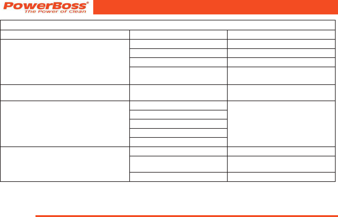
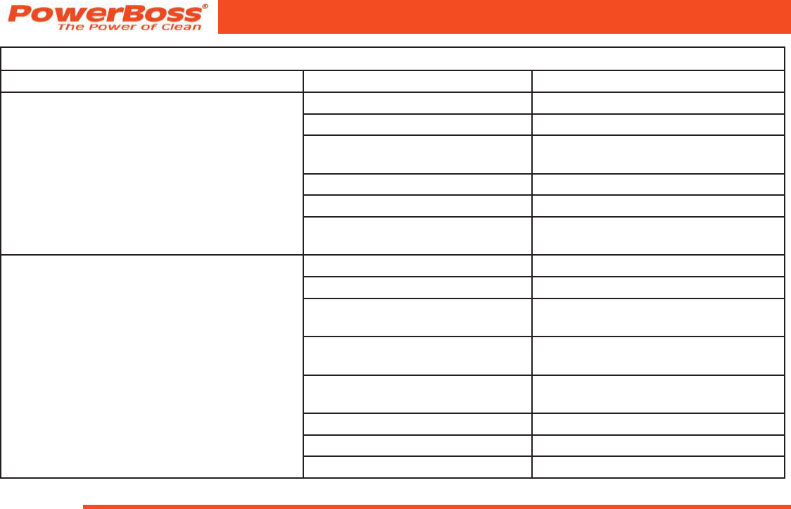
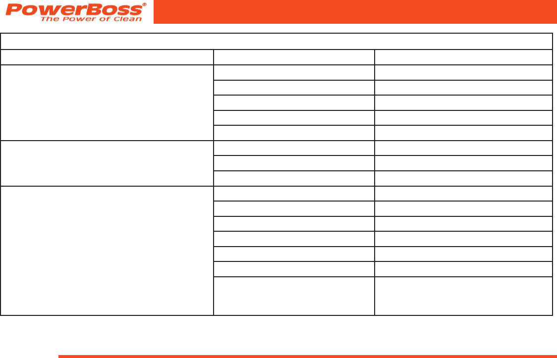
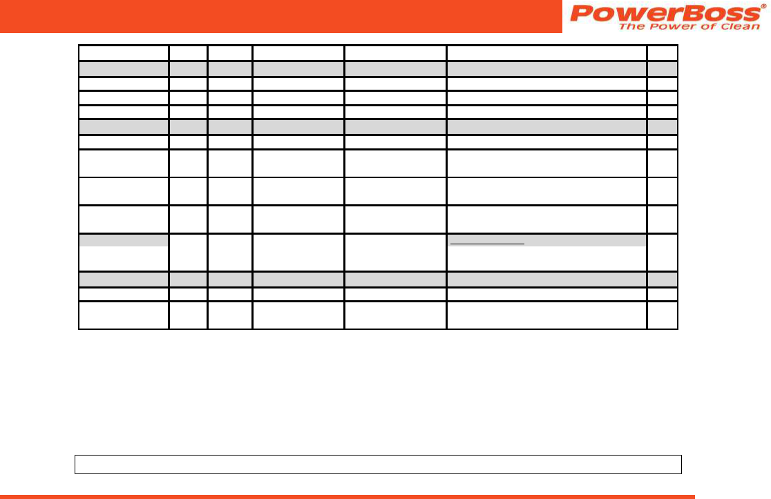
Travel *Labor PartsEngineExtended WarrantyCosts
Walk Behind
****
Battery Sweepers90 Days12 months12 monthsN/AN/A-
IC Sweepers90 Days12 months12 monthsThrough Eng. Mfg.N/A-
Battery Scrubbers90 Days24 months36 monthsN/AN/A-
Riders
Battery Scrubbers90 Days24 months36 months or 2000 hr.N/A36 months parts + 24 labor (or 3000 Hours)5%
IC Sweeper/Scrubbers
82 & 90
90 Days6 months24 months or 2000 hr.24 months or 3000 hrs**
Minuteman International owner of PowerBoss warrants to the original purchaser/user that the product is free from defects in workmanship and materials
under normal use. PowerBoss will, at its option, repair or replace without charge, parts that fail under normal use and service when operated and
maintained in accordance with the applicable operation and instruction manuals. All warranty claims must be submitted through and approved by factory
authorized repair stations.
This warranty does not apply to normal wear, or to items whose life is dependent on their use and care. Parts not manufactured by PowerBoss are covered by and
subject to the warranties and/or guarantees of their manufacturers. Please contact Minuteman International for procedures in warranty claims against these
manufacturers.
Special warning to purchaser-- Use of replacement parts not manufactured by PowerBoss or its designated licensees, will void all warranties
expressed or implied. A potential health hazard exits without original equipment replacement.
All warranted items become the sole property of Minuteman International or PowerBoss or its original manufacturer, whichever the case may be.
PowerBoss disclaims any implied warranty, including the warranty of merchantability and the warranty of fitness for a particular purpose. PowerBoss
assumes no responsibility for any special, incidental or consequential damages.
This limited warranty is applicable only in the U.S.A. and Canada, and is extended only to the original user/purchaser of this product. Customers outside
the U.S.A. and Canada should contact their local distributor for export warranty policies. PowerBoss is not responsible for costs or repairs performed by
persons other than those specifically authorized by PowerBoss. This warranty does not apply to damage from transportation, alterations by unauthorized
persons, misuse or abuse of the equipment, use of non-compatible chemicals, or damage to property, or loss of income due to malfunctions of the
product. If a difficulty develops with this machine, you should contact the dealer from whom it was purchased.
This warranty gives you specific legal rights, and you may have other rights, which vary from state to state. Some states do not allow the exclusion or
limitation of special, incidental or consequential damages, or limitations on how long an implied warranty lasts, so the above exclusions and limitations
may not apply to you.
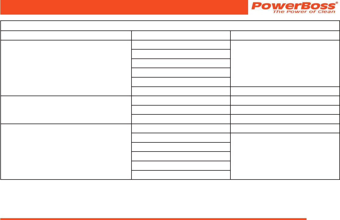
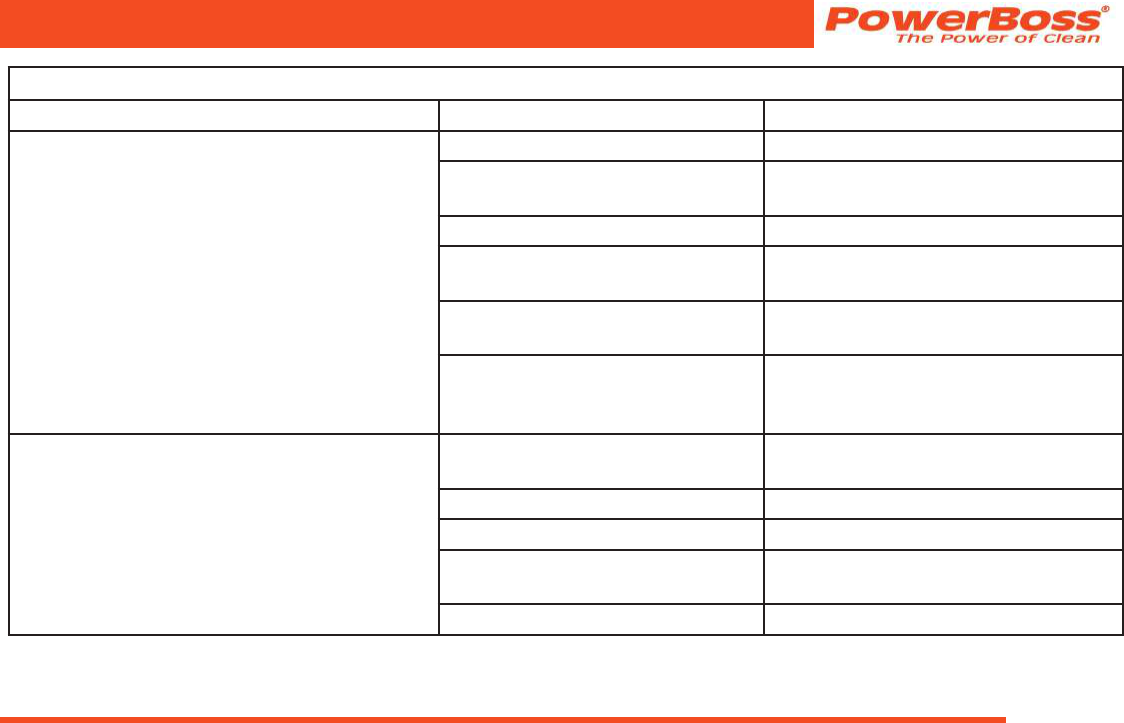
Travel *Labor PartsEngineExtended WarrantyCosts
Walk Behind
****
Battery Sweepers90 Days12 months12 monthsN/AN/A-
IC Sweepers90 Days12 months12 monthsThrough Eng. Mfg.N/A-
Battery Scrubbers90 Days24 months36 monthsN/AN/A-
Riders
Battery Scrubbers90 Days24 months36 months or 2000 hr.N/A36 months parts + 24 labor (or 3000 Hours)5%
IC Sweeper/Scrubbers
82 & 90
90 Days6 months24 months or 2000 hr.24 months or 3000 hrs**
Gebruikershandleiding.com neemt misbruik van zijn services uitermate serieus. U kunt hieronder aangeven waarom deze vraag ongepast is. Wij controleren de vraag en zonodig wordt deze verwijderd.
Product:
Spelregels forum
Om tot zinvolle vragen te komen hanteren wij de volgende spelregels:
lees eerst de handleiding door;
controleer of uw vraag al eerder door iemand anders is gesteld;
probeer uw vraag zo duidelijk mogelijk te stellen;
heeft u een probleem en al geprobeerd om dit op te lossen, vermeld dit erbij aub;
heeft u een oplossing gekregen van een bezoeker dan horen wij dat graag in dit forum;
wilt u een reactie geven op een vraag of antwoord, gebruik dan niet dit formulier maar klik op de knop 'reageer op deze vraag';
uw vraag wordt direct op de website gezet; vermijd daarom persoonlijke gegevens in te vullen;
Belangrijk! Als er een antwoord wordt gegeven op uw vraag, dan is het voor de gever van het antwoord nuttig om te weten als u er wel (of niet) mee geholpen bent! Wij vragen u dus ook te reageren op een antwoord.
Belangrijk! Antwoorden worden ook per e-mail naar abonnees gestuurd. Laat uw emailadres achter op deze site, zodat u op de hoogte blijft. U krijgt dan ook andere vragen en antwoorden te zien.
Abonneren
Abonneer u voor het ontvangen van emails voor uw PowerBoss Armadillo 9X Sweeper bij:
nieuwe vragen en antwoorden
nieuwe handleidingen
U ontvangt een email met instructies om u voor één of beide opties in te schrijven.
Ontvang uw handleiding per email
Vul uw emailadres in en ontvang de handleiding van PowerBoss Armadillo 9X Sweeper in de taal/talen: Engels als bijlage per email.
De handleiding is 3,46 mb groot.
U ontvangt de handleiding per email binnen enkele minuten. Als u geen email heeft ontvangen, dan heeft u waarschijnlijk een verkeerd emailadres ingevuld of is uw mailbox te vol. Daarnaast kan het zijn dat uw internetprovider een maximum heeft aan de grootte per email. Omdat hier een handleiding wordt meegestuurd, kan het voorkomen dat de email groter is dan toegestaan bij uw provider.
Stel vragen via chat aan uw handleiding
Stel uw vraag over deze PDF
Uw handleiding is per email verstuurd. Controleer uw email
Als u niet binnen een kwartier uw email met handleiding ontvangen heeft, kan het zijn dat u een verkeerd emailadres heeft ingevuld of dat uw emailprovider een maximum grootte per email heeft ingesteld die kleiner is dan de grootte van de handleiding.
Er is een email naar u verstuurd om uw inschrijving definitief te maken.
Controleer uw email en volg de aanwijzingen op om uw inschrijving definitief te maken
U heeft geen emailadres opgegeven
Als u de handleiding per email wilt ontvangen, vul dan een geldig emailadres in.
Uw vraag is op deze pagina toegevoegd
Wilt u een email ontvangen bij een antwoord en/of nieuwe vragen? Vul dan hier uw emailadres in.