BELANGRIJKE VEILIGHEIDSMAAT-
REGELEN ................................................ 3
LEES DEZE INFORMATIE
BETREFFENDE UW
AUTONAVIGATIESYSTEEM
ZORGVULDIG DOOR EN BEWAAR
DE INFORMATIE VOOR
EVENTUELE NASLAG. .......................... 3
Aansluitingen .............................................. 5
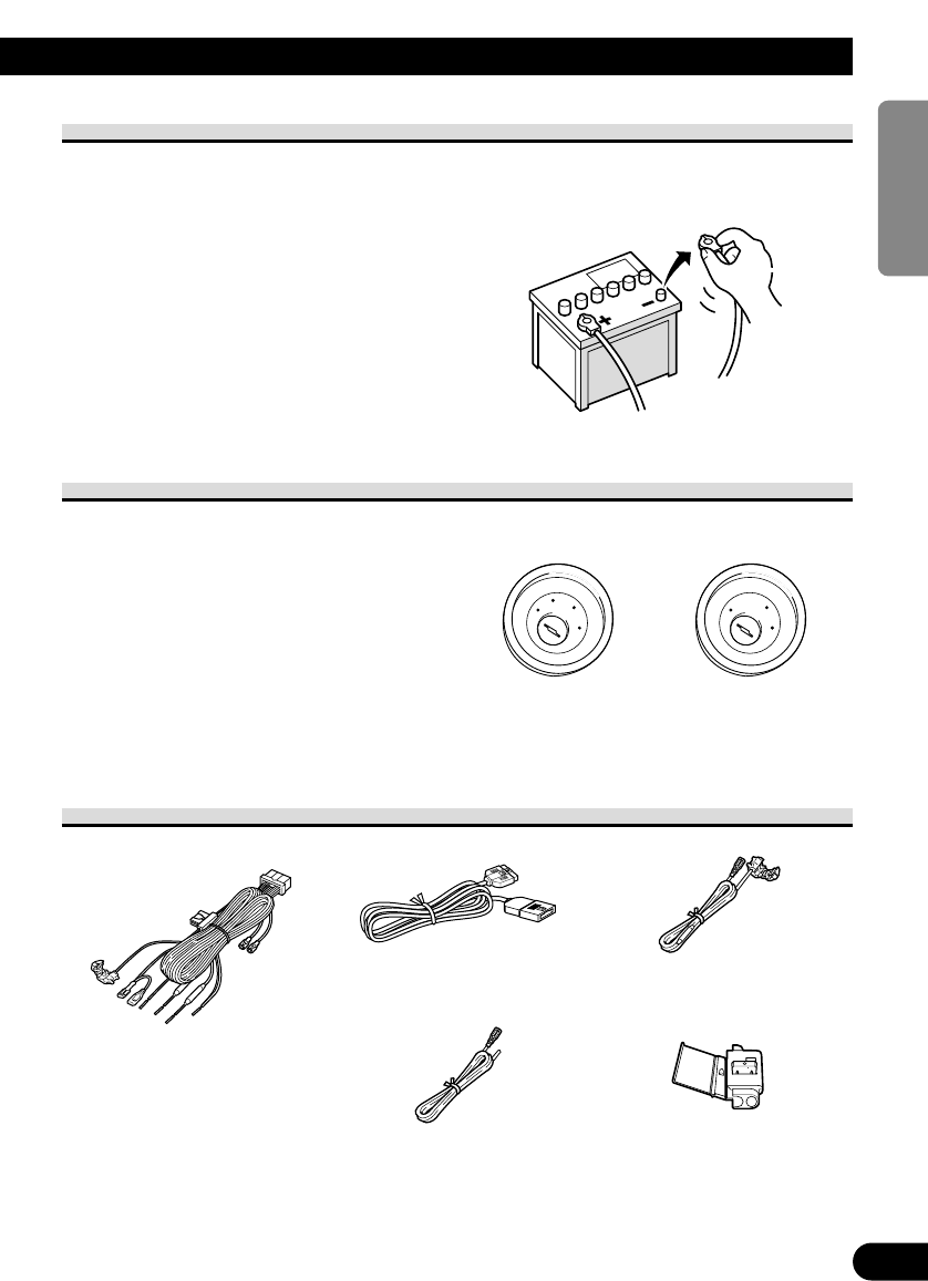
BELANGRIJK .................................................. 5
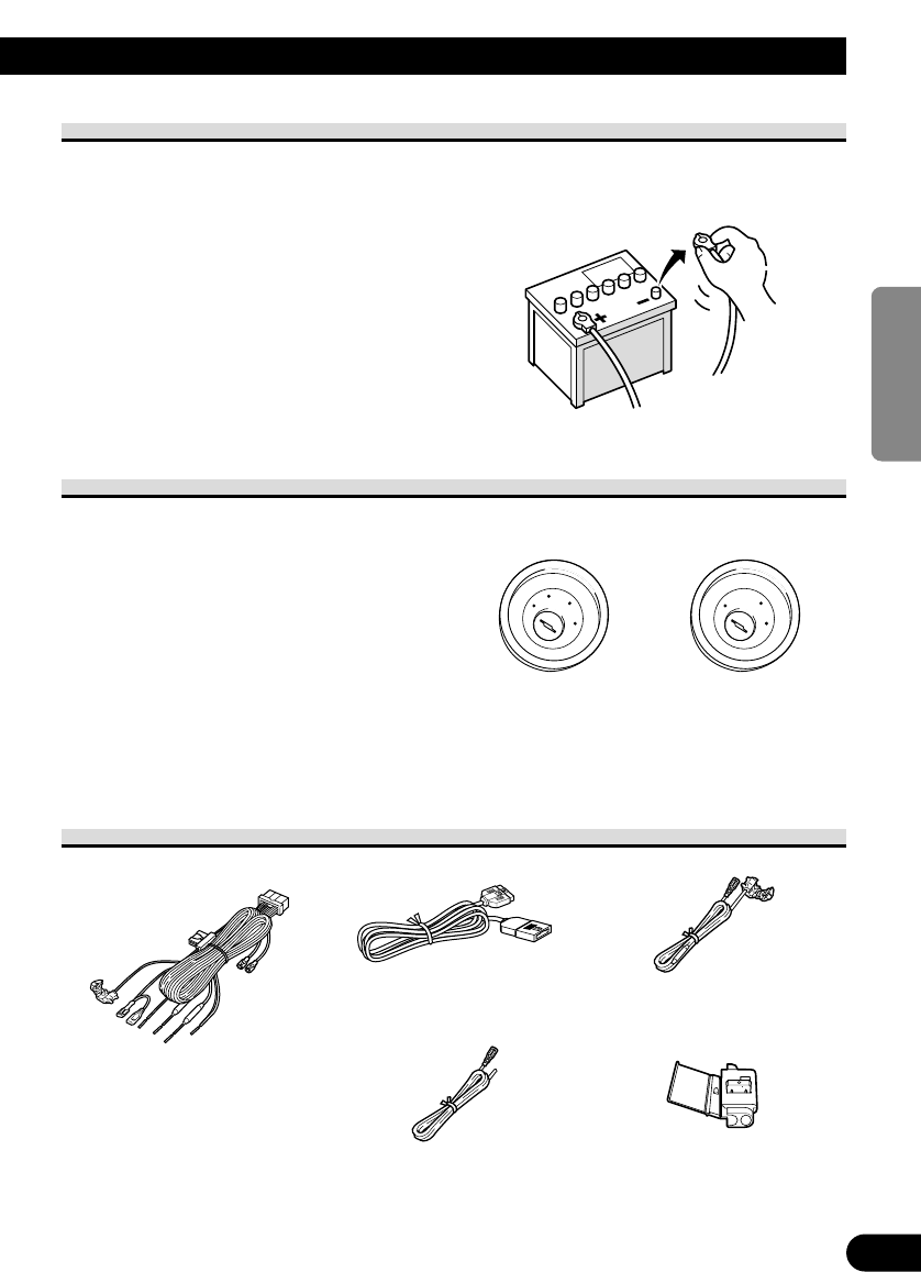
Alvorens u het apparaat inbouwt........................ 6
Voorkomen van beschadigingen ........................ 6
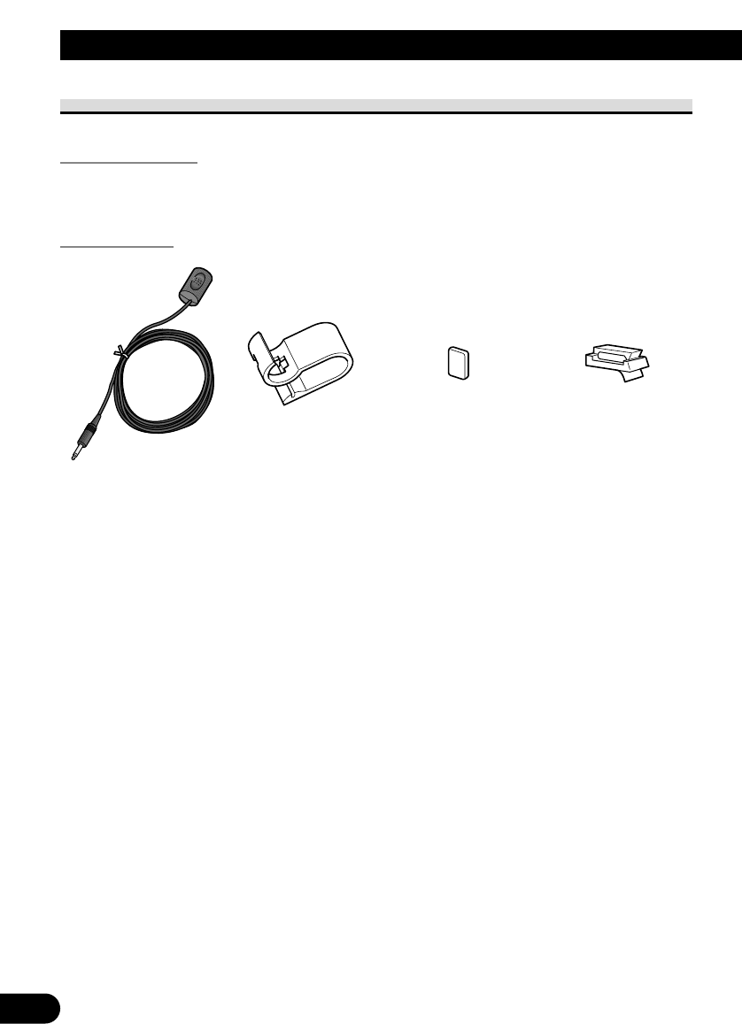
Bijgeleverde accessoires .................................... 6
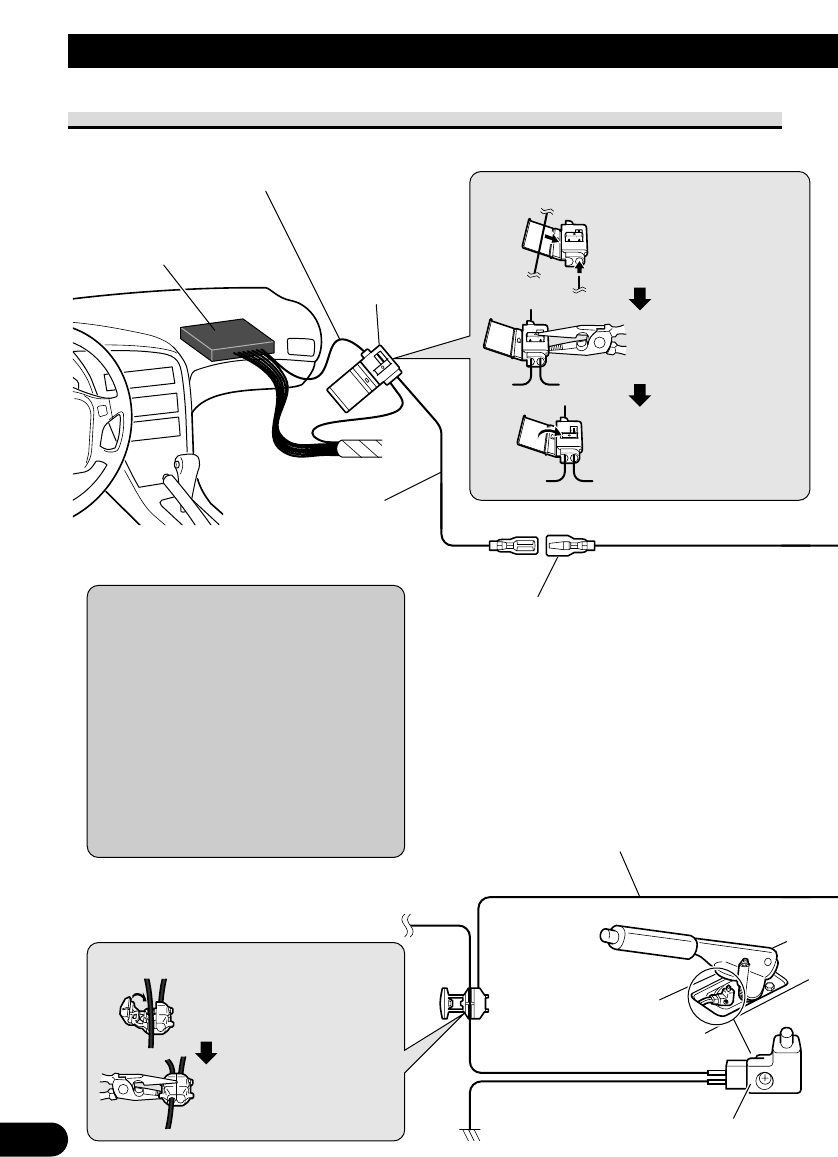
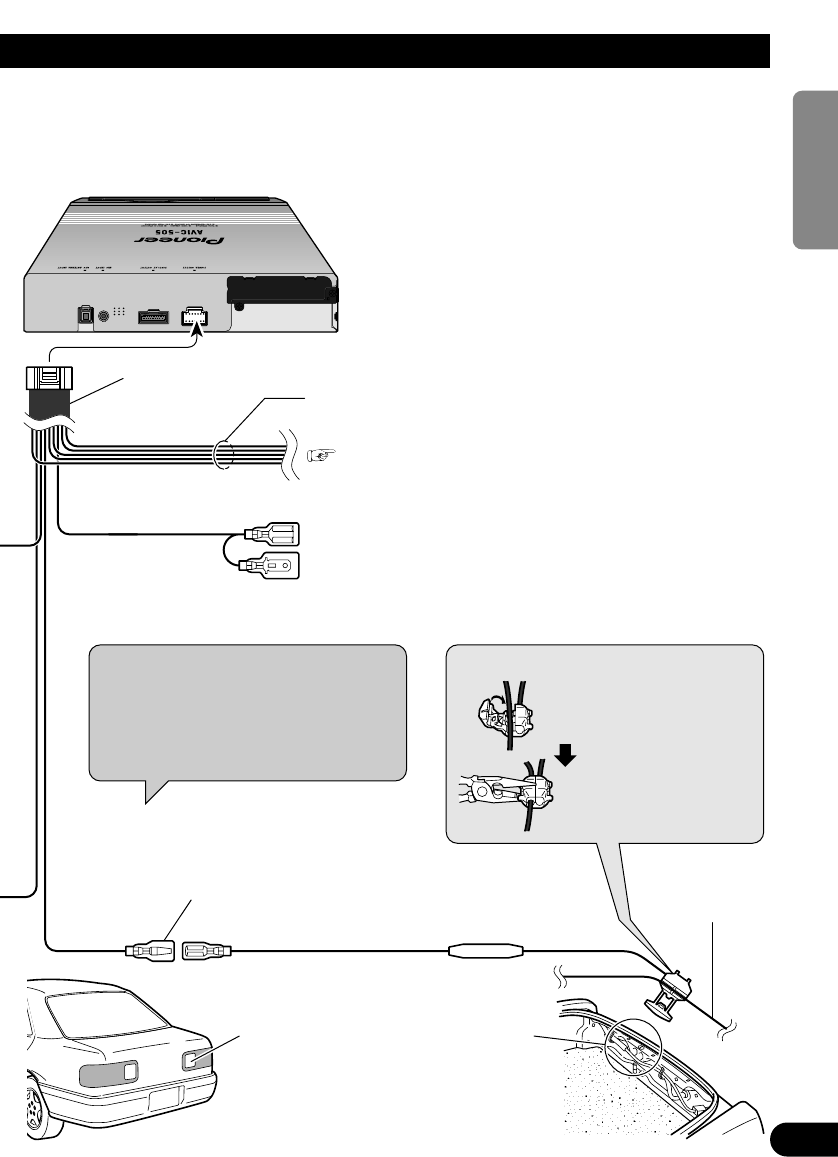
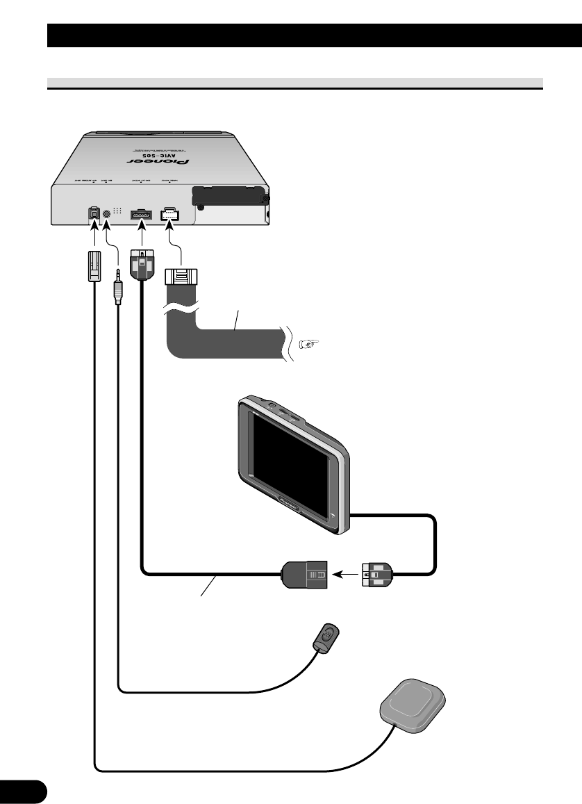
Aansluiten van de systeemcomponenten............ 7
Aansluiten van het stroomsnoer (1) .................. 8
Aansluiten van het stroomsnoer (2) .................. 9
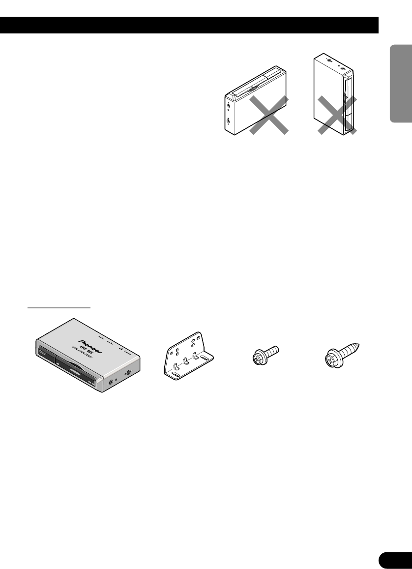
Inbouwen.................................................... 11
BELANGRIJK ................................................ 11
Voorkomen van elektromagnetische storing
in het autonavigatiesysteem .................... 12
Alvorens het apparaat definitief te
bevestigen.................................................. 12
Alvorens de kleefstroken vast te plakken ........ 12
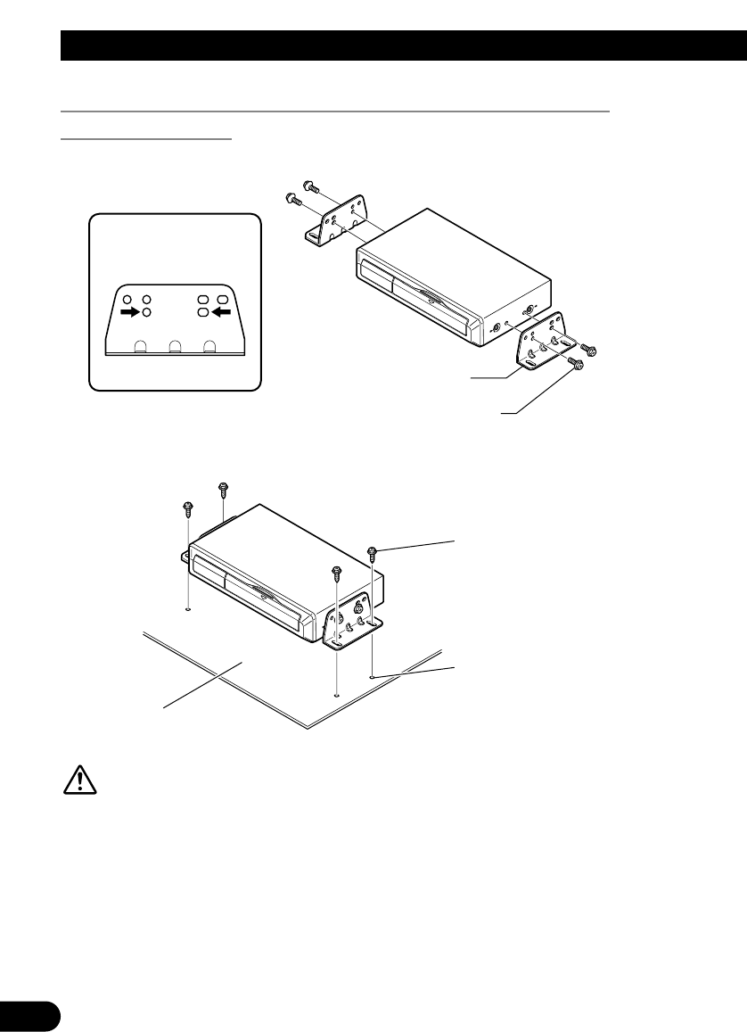
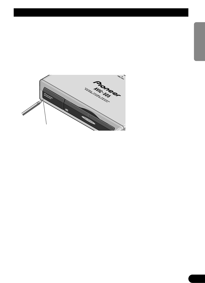
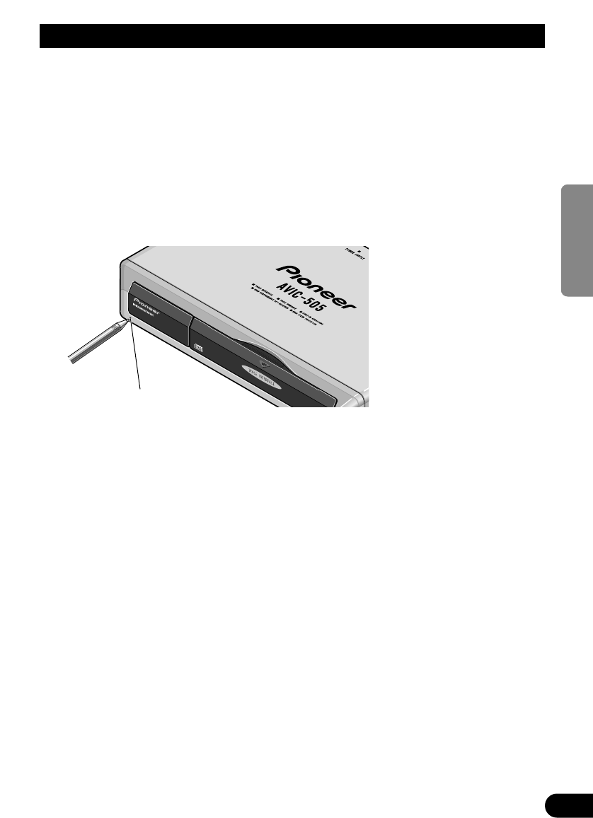
Inbouwen van het hoofdapparaat .................... 13
-
Opmerkingen betreffende het inbouwen
-
Hoofdapparaat en bijgeleverd
montagemateriaal
-
Inbouwen van het apparaat in de koffer-
ruimte, op de vloer onder de stoel, enz.
met behulp van de tapschroeven
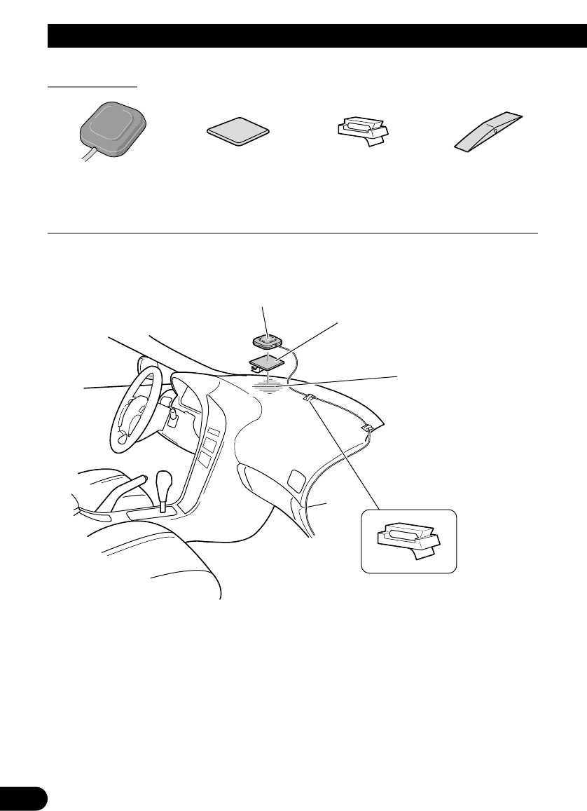
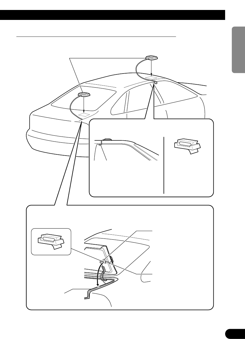
Bevestigen van de GPS antenne ...................... 16
-
BELANGRIJK
-
Opmerkingen betreffende het bevestigen
-
GPS antenne en bijgeleverd
montagemateriaal
-
Bevestigen van de antenne binnenin de
auto (op het dashboard of de
hoedenplank)
-
Bevestigen van de antenne aan de
buitenzijde van de auto (op de
carrosserie)
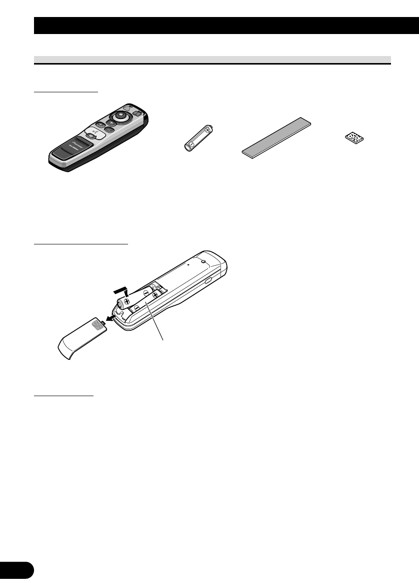
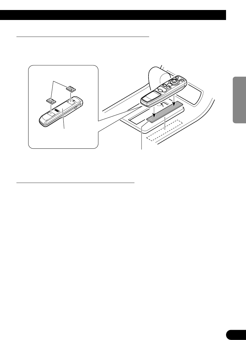
Bevestigen van de afstandsbediening .............. 19
-
Afstandsbediening en bijgeleverde
accessoires
-
Aanbrengen van de batterijen
-
Opmerkingen betreffende de batterijen
-
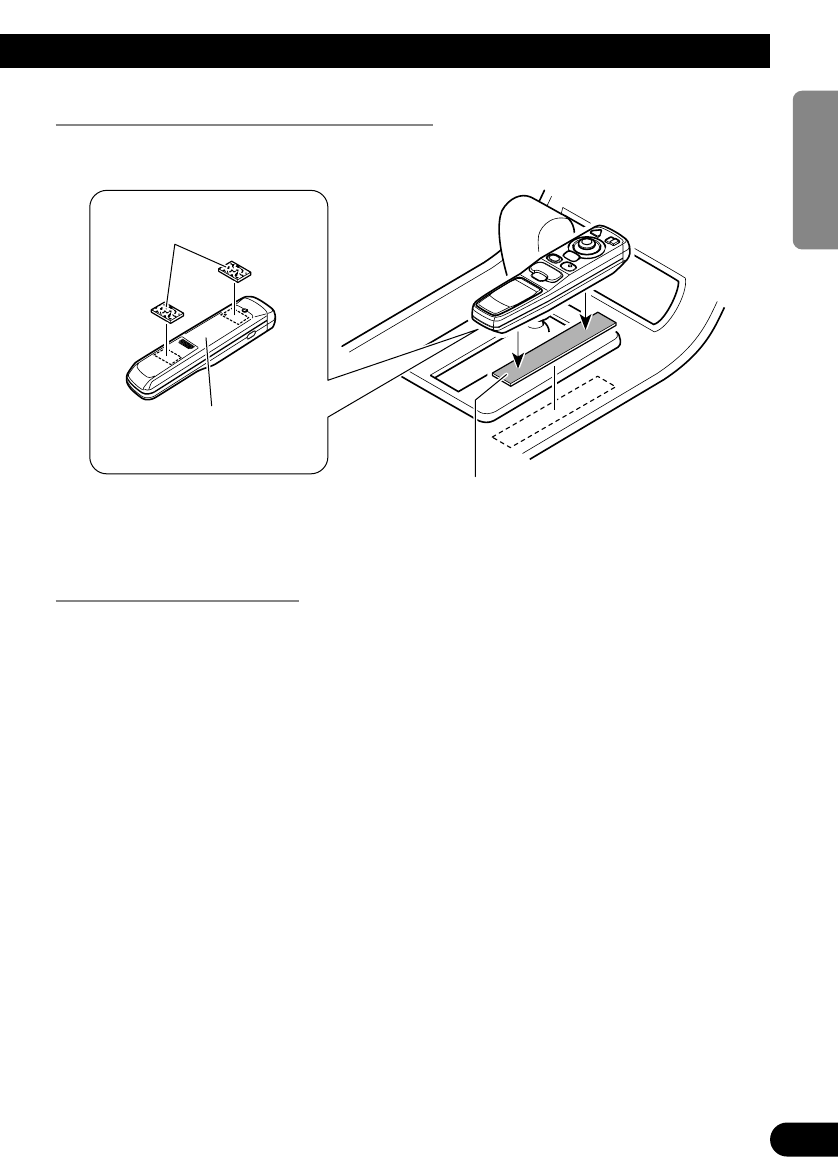
Bevestigen van de afstandsbediening
met het klittenband
-
Behandeling van de afstandsbediening
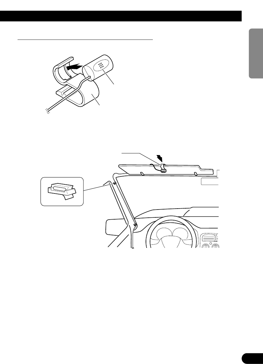
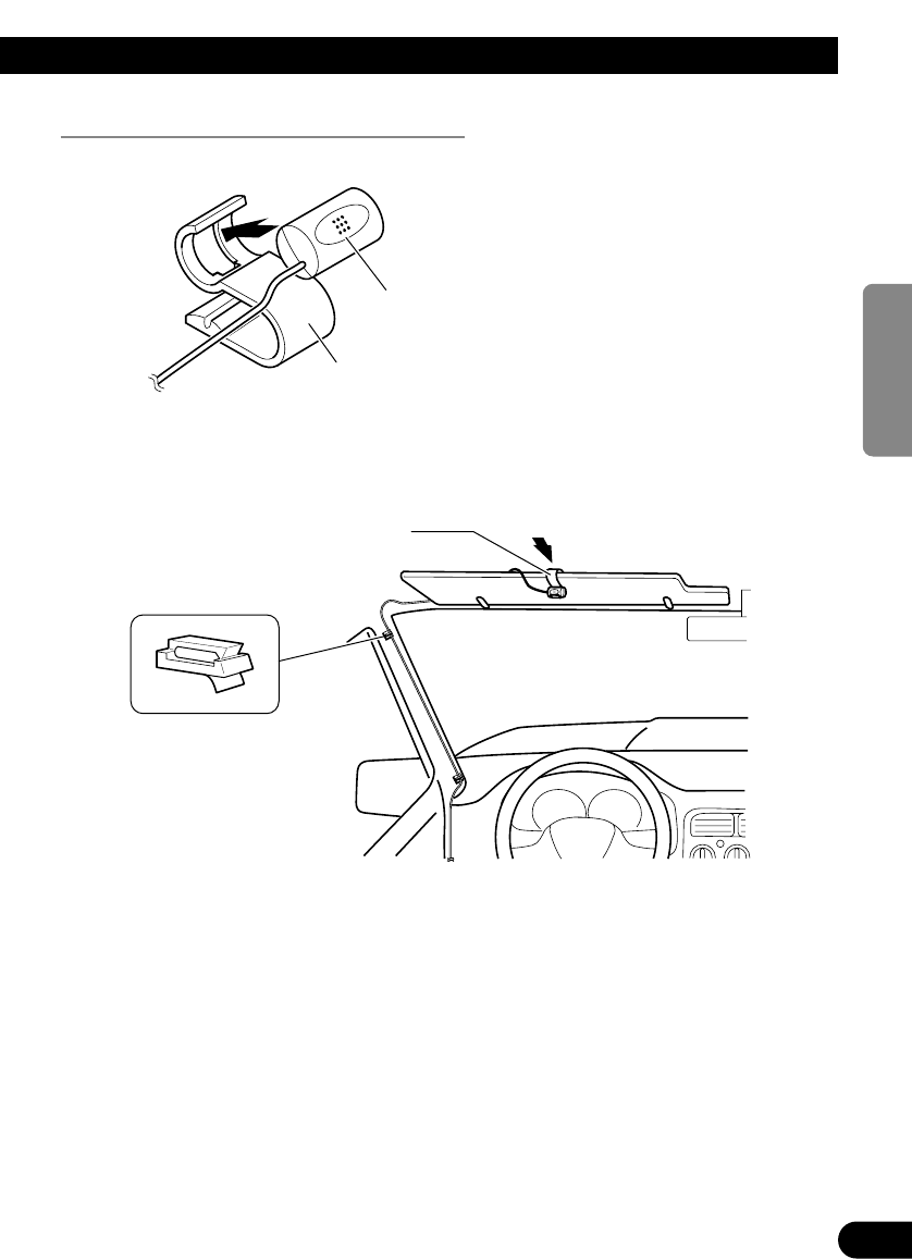
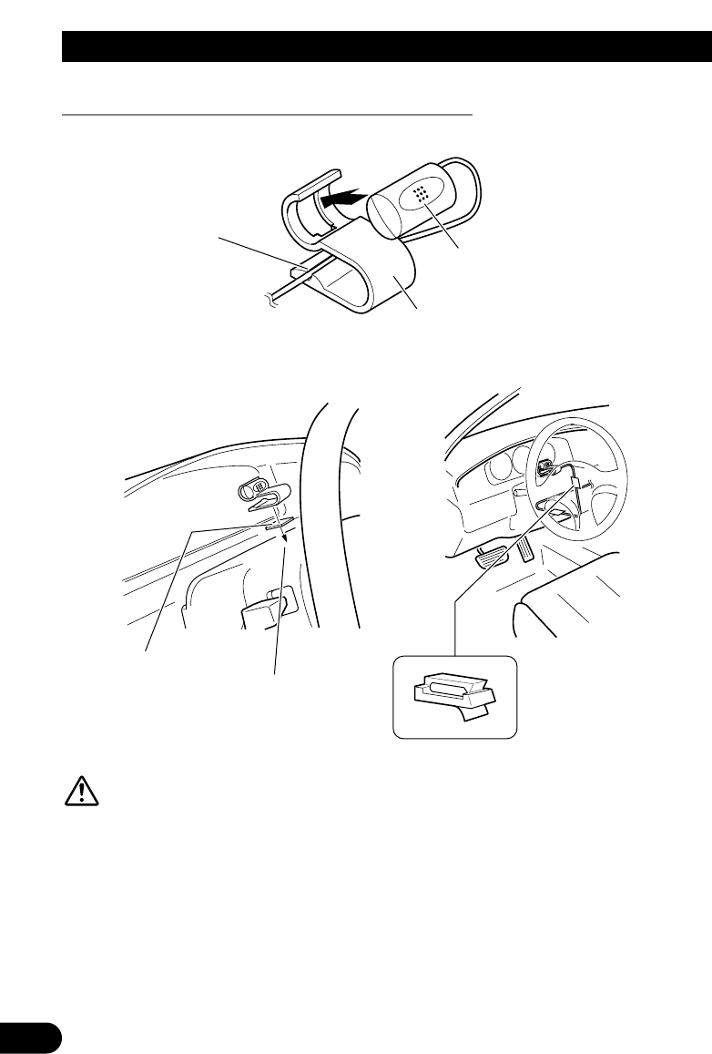
Bevestigen van de microfoon .......................... 21
-
Opmerkingen betreffende de plaats
voor de microfoon
-
Microfoon en bijgeleverd accessoires
-
Bevestigen van de microfoon op de
zonneklep
-
Bevestigen van de microfoon op de
stuurkolom
Nadat het apparaat is ingebouwd ........ 24
2
ENGLISH ESPAÑOL DEUTSCH FRANÇAIS
ITALIANO
NEDERLANDS
Inhoudsopgave