2 VEILIGHEID/AFVOERSYSTEEM
3
Waar u op moet letten
■ Laat het toestel aansluiten door een erkend
installateur (zie hoofdstuk "Installatie").
■ Bij reparatie of schoonmaakbeurten moet
het toestel stroomloos gemaakt worden.
Neem de stekker uit het stopcontact of
draai de schakelaar in de meterkast op nul.
■ Bij koken of braden wordt de kookplaat
heet, dus altijd kinderen uit de buurt
houden.
■ Vet en olie zijn bij oververhitting brandbaar.
Blijf in de buurt tijdens het bereiden van
gerechten.
■ Voordat u met koken begint de afzuigkap
inschakelen. Na het koken de afzuigkap
nog ca. 5 minuten aan laten staan.
■ Een met vet verzadigd filter is brandbaar.
Nooit onder de afzuigkap flamberen en op
tijd het filter schoonmaken.
■ Maak eerst het toestel stroomloos als u de
lampen wilt vervangen! Gebruik uitsluitend
dezelfde lampen met aangegeven wattage.
■ In verband met eventuele scherpe randen
van de ombouwkoker adviseren wij u om
tijdens de montage van de koker
werkhandschoenen te gebruiken.
■ De randen van het filterraam kunnen
scherp zijn. Monteer de meegeleverde
beschermstrips op de randen van het
filterraam.
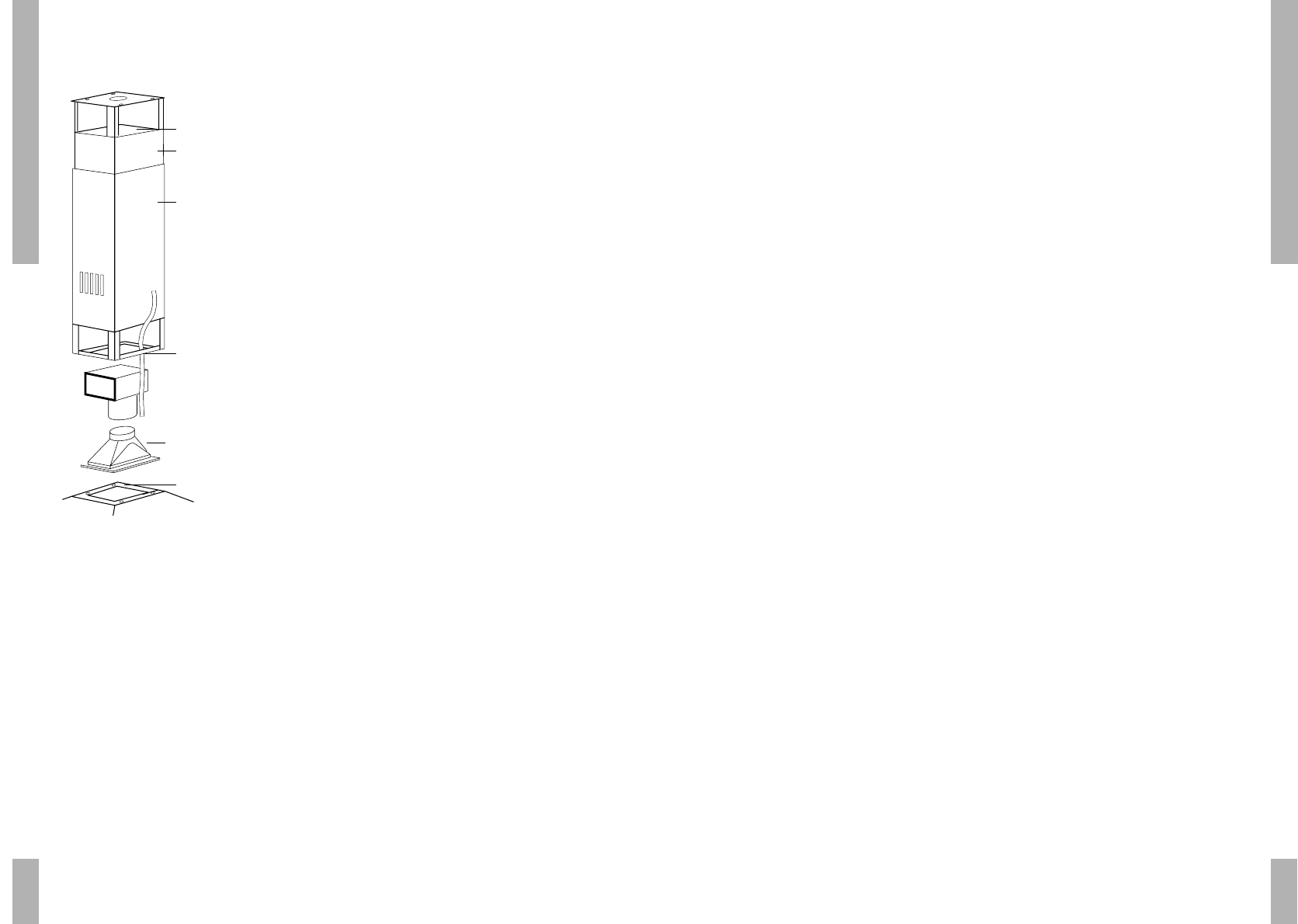
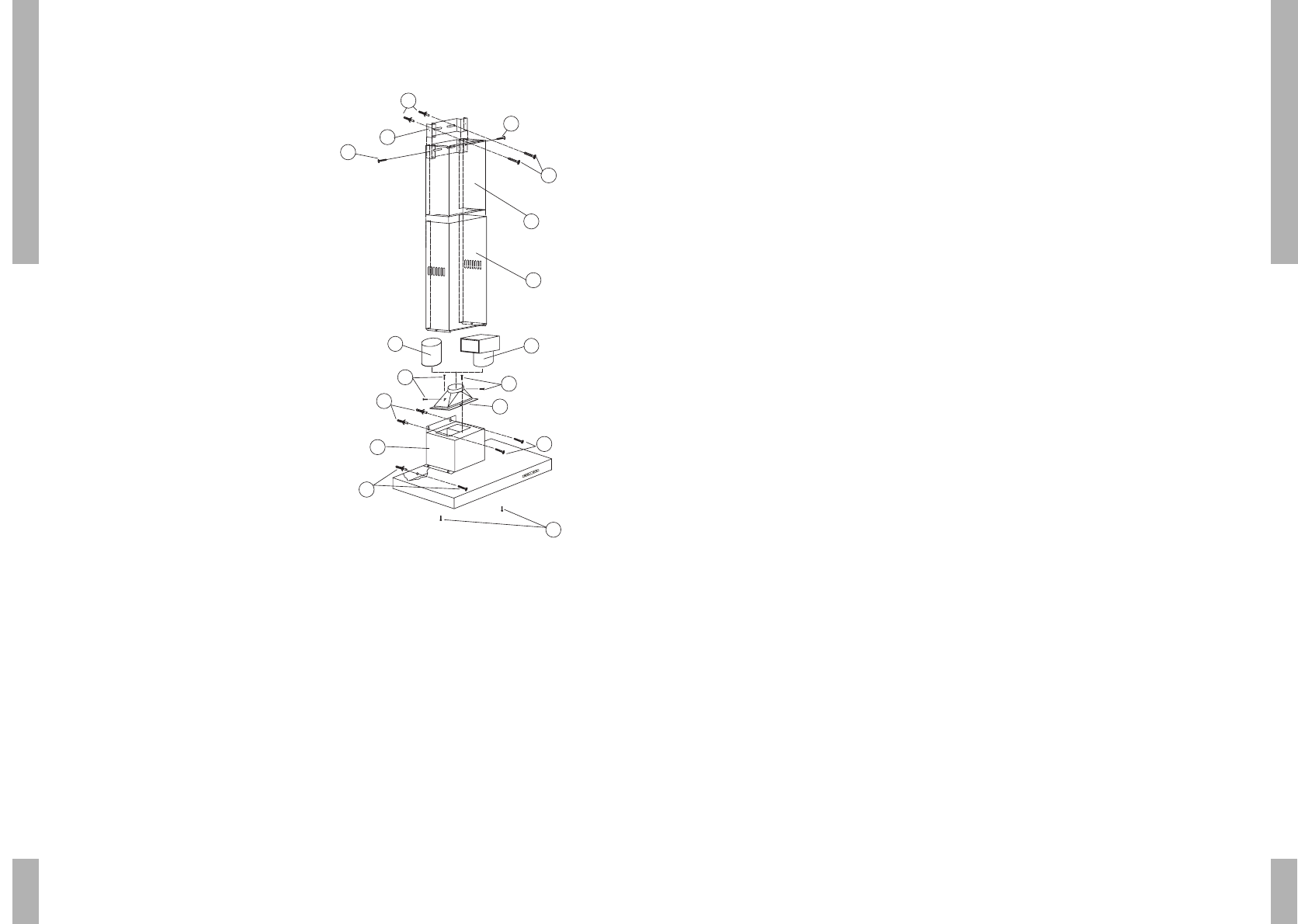
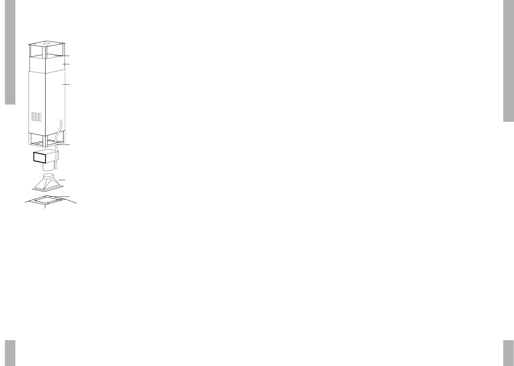
Afvoersystemen
Afhankelijk van het type kan de afzuigkap op
twee manieren worden aangesloten:
■ Op een afvoerkanaal.
De aangezogen kookdampen worden naar
buiten afgevoerd, nadat de vetdeeltjes
gefilterd zijn. Dit is de beste manier! De
afzuigkap wordt aangesloten aan de
bovenzijde met behulp van het bijgesloten
aansluitpijpmondje op het afvoerkanaal.
■ Als circulatiekap.
De vetdeeltjes en de geur uit de
aangezogen kookdampen worden gefilterd.
De aangezogen lucht wordt niet afgevoerd
maar circuleert via T-stuk (B) door de
roosters (A) van de koker in de keuken. U
moet dan wel een koolstoffilter plaatsen.
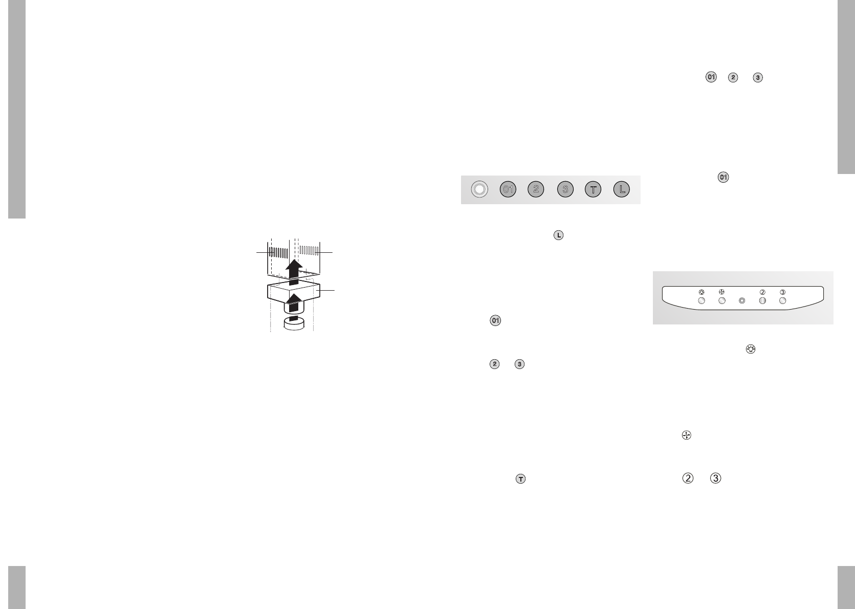
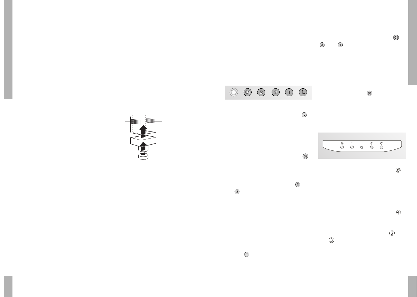
BEDIENING
Bediening
Ingebruikname
Als u de afzuigkap voor de eerste keer
gebruikt, start de kap in de testfase. Aan het
eind van deze fase schakelt de kap over naar
de stand-by fase. De verlichting en de motor
worden uitgeschakeld.
LSK 945 / 975 / 980 / 980 D / 986/ 998 / 996
Verlichting in- en uitschakelen
Druk op de toets voor de verlichting .
De verlichting gaat branden.
Druk nogmaals op de toets en de verlichting
gaat uit.
Ventilator inschakelen
De afzuigkap wordt ingeschakeld door op
toets te drukken.
Wijzig de snelheid door motorsnelheids-
schakelaars of te drukken.
Intensiefstand
U kunt u de afzuigkap tijdelijk in de hoogste
stand inschakelen, bijvoorbeeld om snel de
geur af te voeren als er iets aangebrand is.
Druk op toets om de intensiefstand in te
schakelen. De afzuigkap schakelt gedurende 5
minuten in op zijn hoogste stand (4) en keert
daarna terug naar de oorspronkelijke stand.
Timer
Druk gedurende 2 seconden op schakelaar
, of . De afzuigkap blijft nog 5
minuten ingeschakeld op de gekozen stand,
daarna worden de afzuigkap en de verlichting
automatisch uitgeschakeld.
Uitschakelen
Schakel de kap uit door op toets te
drukken. De kap schakelt over naar stand-by.
Als u de kap weer inschakelt gaat de motor
draaien met de laatst gekozen snelheid.
LSK 986 Alu / SKE 905
Verlichting in- en uitschakelen
Druk op de toets voor de verlichting .
De verlichting gaat branden.
Druk nogmaals op de toets en de verlichting
gaat uit.
Ventilator inschakelen
De afzuigkap wordt ingeschakeld door op
toets te drukken.
Wijzig de snelheid door motorsnelheids-
schakelaars of te drukken. De
snelheid wordt met één stap verlaagd of
verhoogd.