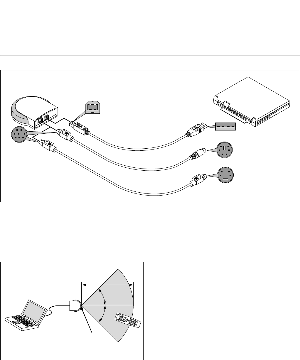
NOTE: When using with a notebook PC, be sure to connect between the projector and the notebook PC before turning on the power to the notebook PC. In most cases
signal cannot be output from RGB output unless the notebook PC is turned on after connecting with the projector.
NOTE:
* If the screen goes blank while using your remote control, it may be the result of the computer’s screen-saver or power management software.
* If you accidentally hit the POWER button on the remote control, wait 60 seconds and then press the POWER button again to resume.
NOTE: If using video, S-video, or audio cables, the cables should be 3 m (9.8 feet) or shorter.
For LT156:
NOTE: Some personal computers or video cards may not offer images correctly on LT156.
To connect a DVI connector on your computer to LT156, attach the supplied DVI-D – DVI-D signal cable to the DVI connector on the projector. If you use a separately
sold DVI cable, images may not be correctly displayed.
NOTE: The DVI connector can accept a maximum resolution of 1024x768(XGA) when DVI (DIGITAL) input is selected.
E – 19
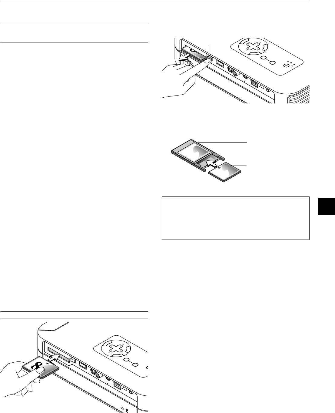
C
C
A
R
D
P
C
C
O
N
T
R
O
L
V
I
D
E
O
D
V
I
-
D
U
S
B
S
-
V
I
D
E
O
A
U
D
I
O
M
E
N
U
E
N
T
E
R
C
A
N
C
E
L
S
E
L
E
C
T
P
O
W
E
R
S
T
A
T
U
S
O
N
/
S
T
A
N
D
B
Y
S
O
U
R
C
E
A
U
T
O
A
D
J
U
S
T
P
C
C
A
R
D
A
C
C
E
S
S
A
C
I
N
EO
DVI-D
S-VID
EO
A
UDIO
DVI
AUDIO
M
E
N
U
E
N
T
E
R
C
A
N
C
E
L
S
E
L
E
C
T
P
O
W
E
R
S
T
A
T
U
S
O
N
/
S
T
A
N
D
B
Y
S
O
U
R
C
E
A
U
T
O
A
D
J
U
S
T
P
C
C
A
R
D
A
C
C
E
S
S
A
C
I
N
C
C
A
R
D
P
C
C
O
N
T
R
O
L
V
I
D
E
O
R
G
B
U
S
B
S
-
V
I
D
E
O
A
U
D
I
O
R
G
B
S
-V
ID
E
O
A
U
D
IO
D
E
O
RGB INPUT
AUDIO
Audio cable (not supplied)
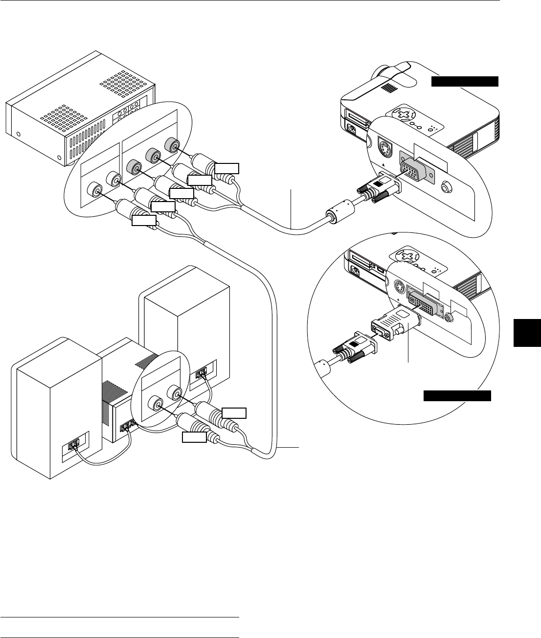
Connecting Your PC
Connecting your PC to your MultiSync LT155 (XGA)/ LT154 (XGA) projector will enable you to project your computer’s screen image for an
impressive presentation.
To connect to a PC, simply:
1.Turn off the power to your projector and computer.
2.Use the supplied signal cable to connect your PC to the projector.
3.Turn on the projector and the computer.
4.If the projector goes blank after a period of inactivity, it may be caused by a screen saver installed on the computer you’ve connected to the
projector.
RGB signal cable (supplied)
To mini D-Sub 15-pin connector on the
projector. It is recommended that you
use a commercially available
distribution amplifier if connecting a
signal cable longer than the supplied
one.
Audio cable (not supplied)
DVI-D – DVI-D signal cable
(supplied)
To DVI connector on the projector.
DVI-A – VGA adapter
(supplied)
IBM VGA or Compatibles
IBM VGA or Compatibles
Connecting Your PC with a DVI Connector
You can connect your PC with a DVI output to your MultiSync LT156 (XGA) projector.
When connecting a PC with a D-sub 15 pin analog connector, attach the supplied DVI-A – VGA adapter to the D-sub 15 pin connector of your PC.
To connect to a PC, simply:
1.Turn off the power to your projector and computer.
2.① Use the supplied DVI-D--DVI-D signal cable to connect a DVI connector of your PC to the projector.
➁ To connect a PC with a mini D-sub 15 pin- mini D-sub 15 pin connector, attach the supplied DVI-A – VGA adapter to the DVI connector on the
projector.
3.Turn on the projector and the computer.
4.If the projector goes blank after a period of inactivity, it may be caused by a screen saver installed on the computer you’ve connected to the
projector.
Mini D-Sub 15 pin connector
LT155/LT154
LT156
DVI connector ①
Mini D-Sub 15
pin connector ➁
RGB signal cable (supplied)
To mini D-Sub 15-pin connector on the projector. It is
recommended that you use a commercially available dis-
tribution amplifier if connecting a signal cable longer than
the supplied one.
Connection Option① when using DVI output.
Connection Option➁ when using mini D-Sub 15 pin output.
E – 20
C
C
A
R
D
P
C
C
O
N
T
R
O
L
V
I
D
E
O
D
V
I
-
D
U
S
B
S
-
V
I
D
E
O
A
U
D
I
O
M
E
N
U
E
N
T
E
R
C
A
N
C
E
L
S
E
L
E
C
T
P
O
W
E
R
S
T
A
T
U
S
O
N
/
S
T
A
N
D
B
Y
S
O
U
R
C
E
A
U
T
O
A
D
J
U
S
T
P
C
C
A
R
D
A
C
C
E
S
S
A
C
I
N
E
O
D
V
I-D
S
-
V
ID
E
O
A
U
D
IO
DVI
AUDIO
M
E
N
U
E
N
T
E
R
C
A
N
C
E
L
S
E
L
E
C
T
P
O
W
E
R
S
T
A
T
U
S
O
N
/
S
T
A
N
D
B
Y
S
O
U
R
C
E
A
U
T
O
A
D
J
U
S
T
P
C
C
A
R
D
A
C
C
E
S
S
A
C
I
N
C
C
A
R
D
P
C
C
O
N
T
R
O
L
V
I
D
E
O
R
G
B
U
S
B
S
-
V
I
D
E
O
A
U
D
I
O
R
G
B
S
-
V
ID
E
O
A
U
D
IOD
E
O
RGB INPUT
AUDIO
RGB Signal cable (supplied)
Audio cable (not supplied)
1
O
N
D
I
P
23
456
Pin adapter for Macintosh
(not supplied)
For older Macintosh, use a commercially
available pin adapter to connect to your
Mac's video port.
Connecting Your Macintosh Computer
Macintosh (Desktop type)
RGB Signal cable (supplied)
Audio cable (not supplied)
DVI-A – VGA adapter
(supplied)
To connect to a Macintosh, simply:
1.Turn off the power to your projector and your Macintosh computer.
2.Use the supplied signal cable to connect your Macintosh computer to the
projector.
3.Turn on the projector and the Macintosh computer.
For LT156:
When connecting a Macintosh with a mini D-sub 15 pin analog connector,
attach the supplied DVI-A – VGA adapter to the DVI connector on the projec-
tor.
Macintosh (Notebook type)
LT155/LT154
LT156
E – 21
M
E
N
U
E
N
T
E
R
C
A
N
C
E
L
SELE
CT
POW
ER
STATUS
ON
/
STAND BY
SOURCE
AUTO
ADJUST
PC CARD
ACC
ESS
AC
IN
C
C
A
R
D
P
C
C
O
N
T
R
O
L
V
ID
E
O
R
G
B
U
S
B
S
-V
ID
E
O
A
U
D
IO
RGB
S-VIDEO
AUDIO
DEO
RGB INPUT
Y Cb Cr
R L
AUDIO
R L
AUDIO
Red
White
Y
Cb
Cr
Red
White
DVD player
Audio cable (not supplied)
Audio Equipment
Connecting Your DVD Player
You can connect your projector to a DVD player with component out-
puts or Video output. To do so, simply:
1.Turn off the power to your projector and DVD player.
2.If your DVD player has the component video (Y,Cb,Cr) output, use
the optional 15-pin-to-RCAן3 cable to connect your DVD player to
the RGB INPUT connector on the projector.
For a DVD player without component video (Y,Cb,Cr) outputs, use
common RCA cables (not provided) to connect a composite VIDEO
output of the DVD player to the Video Input of the projector.
3.Turn on the projector and DVD player.
NOTE: Refer to your DVD player’s owner’s manual for more information about
your DVD player’s video output requirements,
Optional 15-pin-to-
RCAן3 cable (optional)
(Component V )
M
E
N
U
E
N
T
E
R
C
A
N
C
E
L
SELECT
POW
ER
STATUS
ON
/
STAND BY
SOURCE
AUTO
ADJUST
PC CARD
ACCESS
AC IN
C
C
A
R
D
P
C
C
O
N
T
R
O
L
V
ID
E
O
R
G
B
U
S
B
S
-V
ID
E
O
A
U
D
I
O
E
O
D
V
I-
D
S
-
V
ID
E
O
A
U
D
I
O
DVI-D
AUDIO
DVI-A – VGA adapter
(supplied)
LT155 / LT154
For LT156:
Attach the supplied DVI-A--VGA adapter to the DVI connector on your
projector.
LT155/LT154
LT156
E – 22
M
E
N
U
E
N
T
E
R
C
A
N
C
E
L
SELECT
POWER
STATUS
ON
/
STAND BY
SOURCE
AUTO
ADJUST
PC CARD
ACCESS
AC IN
C CAR
D
PC CO
N
TR
OL
VIDEO
R
G
B
U
SB
S-V
ID
E
O
AU
D
IO
RGB
S-VIDEO
PC CONTROL
VIDEO
USB
S-VIDEO
VIDEO
R L
S-VIDEO
AUDIO
R L
AUDIO
VIDEO
VCR/ Laser disc player
S-video cable (not supplied)
Audio equipment
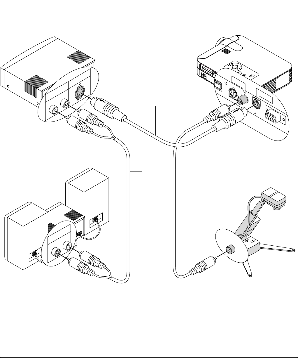
Connecting Your VCR or Laser Disc Player
Use common RCA cables (not provided) to connect your VCR, laser disc player or document camera to your projector.
To make these connections, simply:
1.Turn off the power to the projector and VCR, laser disc player or document camera.
2. Connect one end of your RCA cable to the video output connector on the back of your VCR or laser disc player, connect the other end to the Video
input on your projector. Use an audio cable (not supplied) to connect the audio from your VCR or laser disc player to your audio equipment (if your
VCR or laser disc player has this capability). Be careful to keep your right and left channel connections correct for stereo sound.
3.Turn on the projector and the VCR or laser disc player.
NOTE: Refer to your VCR or laser disc player owner’s manual for more information about your equipment’s video output requirements.
Audio cable
(not supplied)
Video cable
(not supplied)
Document camera
E – 23
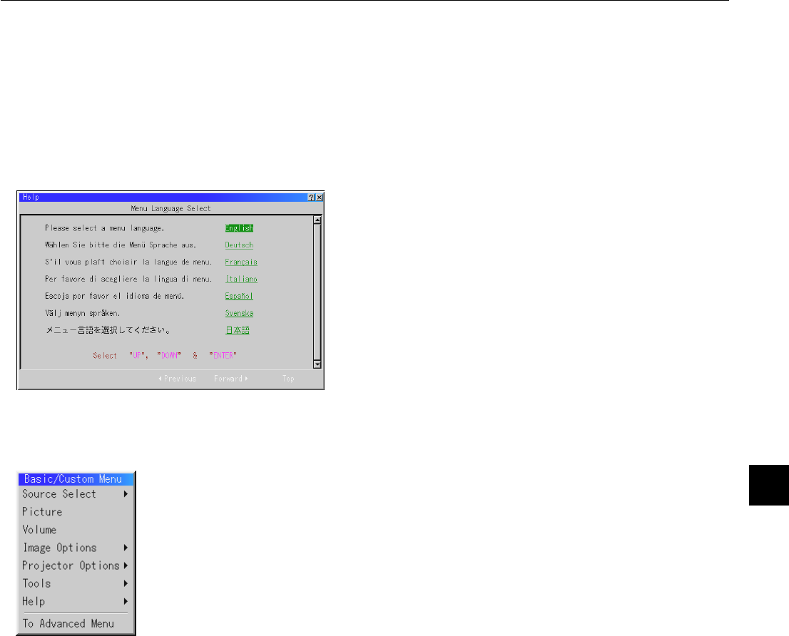
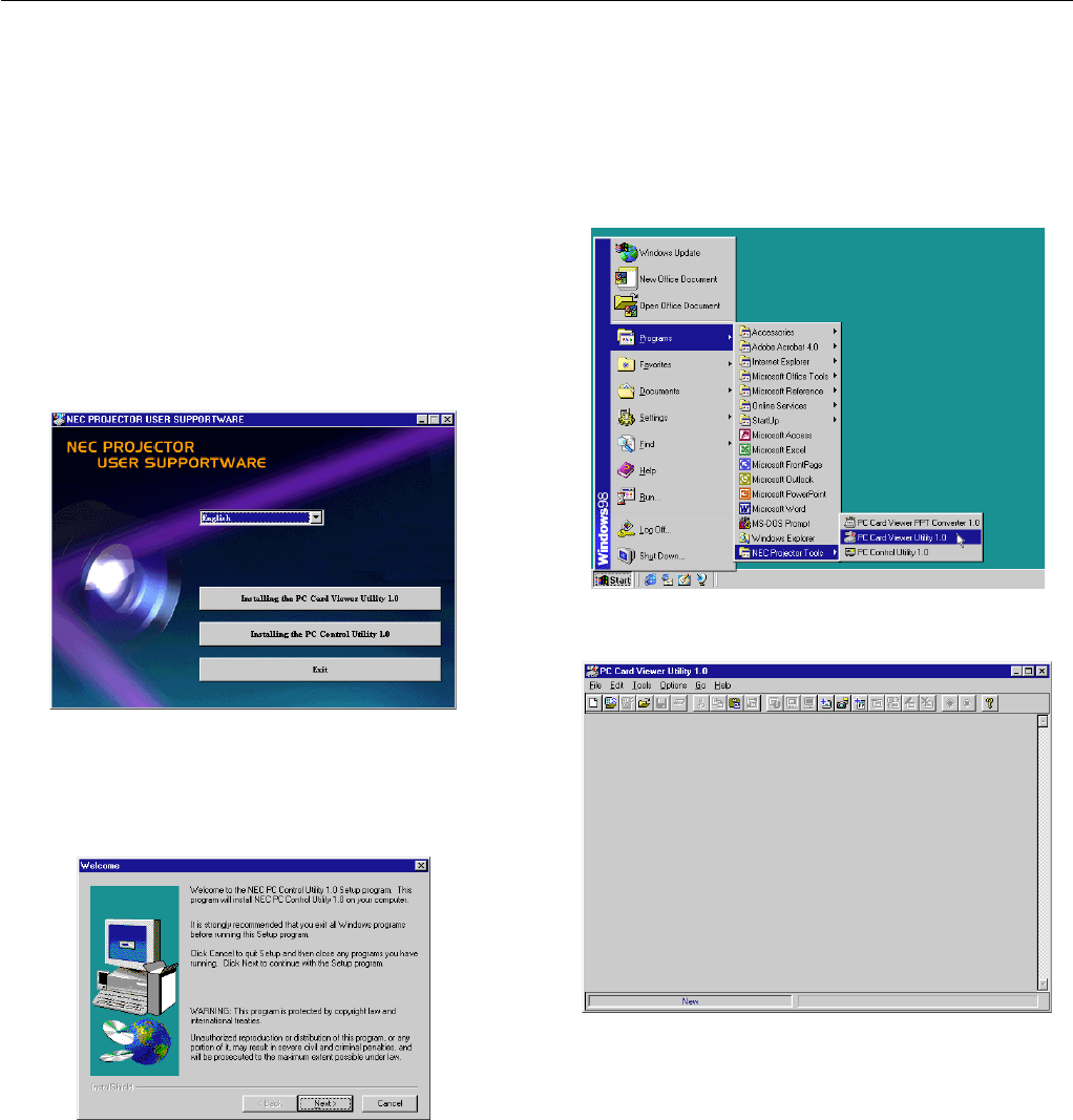
About Startup screen
(Menu Language Select screen)
When you first turn on the projector, you will get the Startup screen.
This screen gives you the opportunity to select one of the seven menu
languages: English, German, French, Itilan, Spanish,Swedish and Japa-
nese.
To select a menu language, follow these steps:
1.Use the Select ▲ or ▼ button to select one of the seven languages
for the menu.
2.Press the Enter button to execute the selection.
3.The Basic/Custom menu will be displayed in the language you
have selected.
To close the menu, press the Cancel button.
After this has been done, you can proceed to the advanced menu op-
eration.
If you want, you can select the menu language later. See “Language”
on page E-36.
E – 24
3. OPERATION
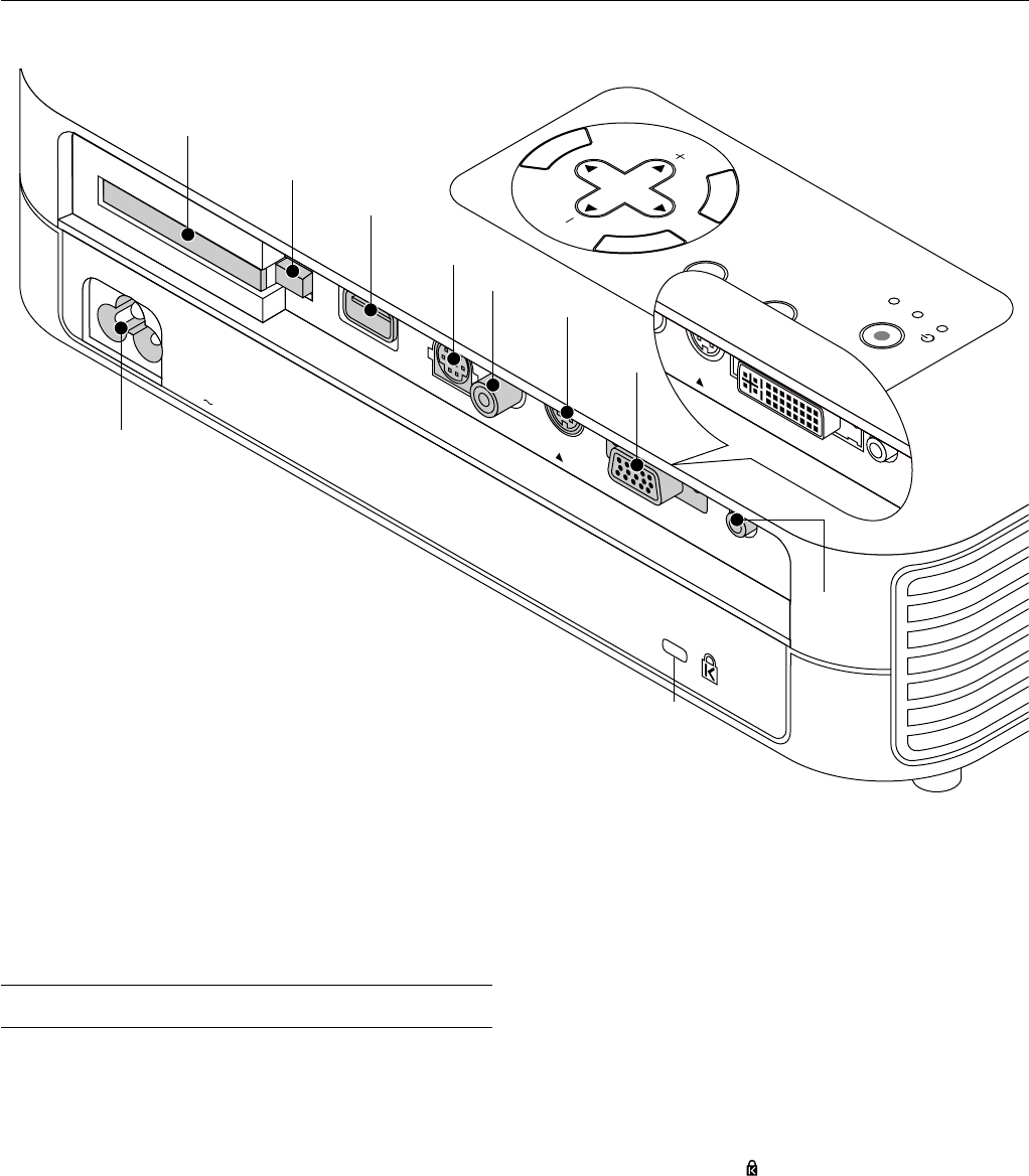
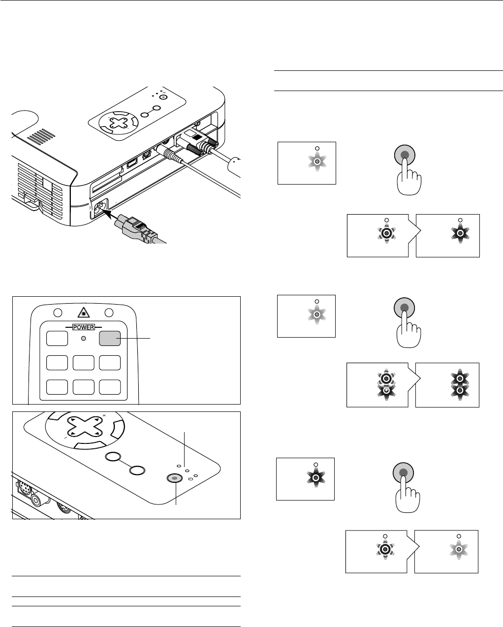
Connecting the Power Cable and Turn on the
Projector
Before you turn on your projector, ensure that the computer or video
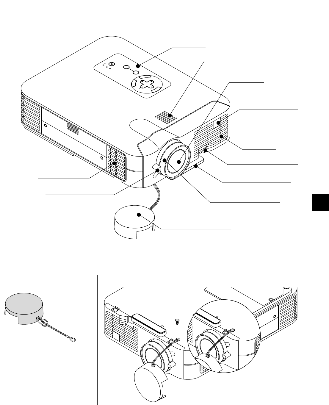
source is turned on and that your lens cap is removed.
1.Connect the supplied power cable to the projector.
M
E
N
U
E
N
T
E
R
C
A
N
C
E
L
S
E
L
E
C
T
P
O
W
E
R
S
T
A
T
U
S
O
N
/
S
T
A
N
D
B
Y
S
O
U
R
C
E
A
U
T
O
A
D
J
U
S
T
P
C
C
A
R
D
A
C
C
E
S
S
A
C
I
N
C
C
A
R
D
U
S
B
P
C
C
O
N
T
R
O
L
V
ID
E
O
S
-V
ID
E
O
R
G
B
A
U
D
IO
Plug the supplied power cable in the wall outlet. The projector will
go into its standby mode and the power indicator will glow orange.
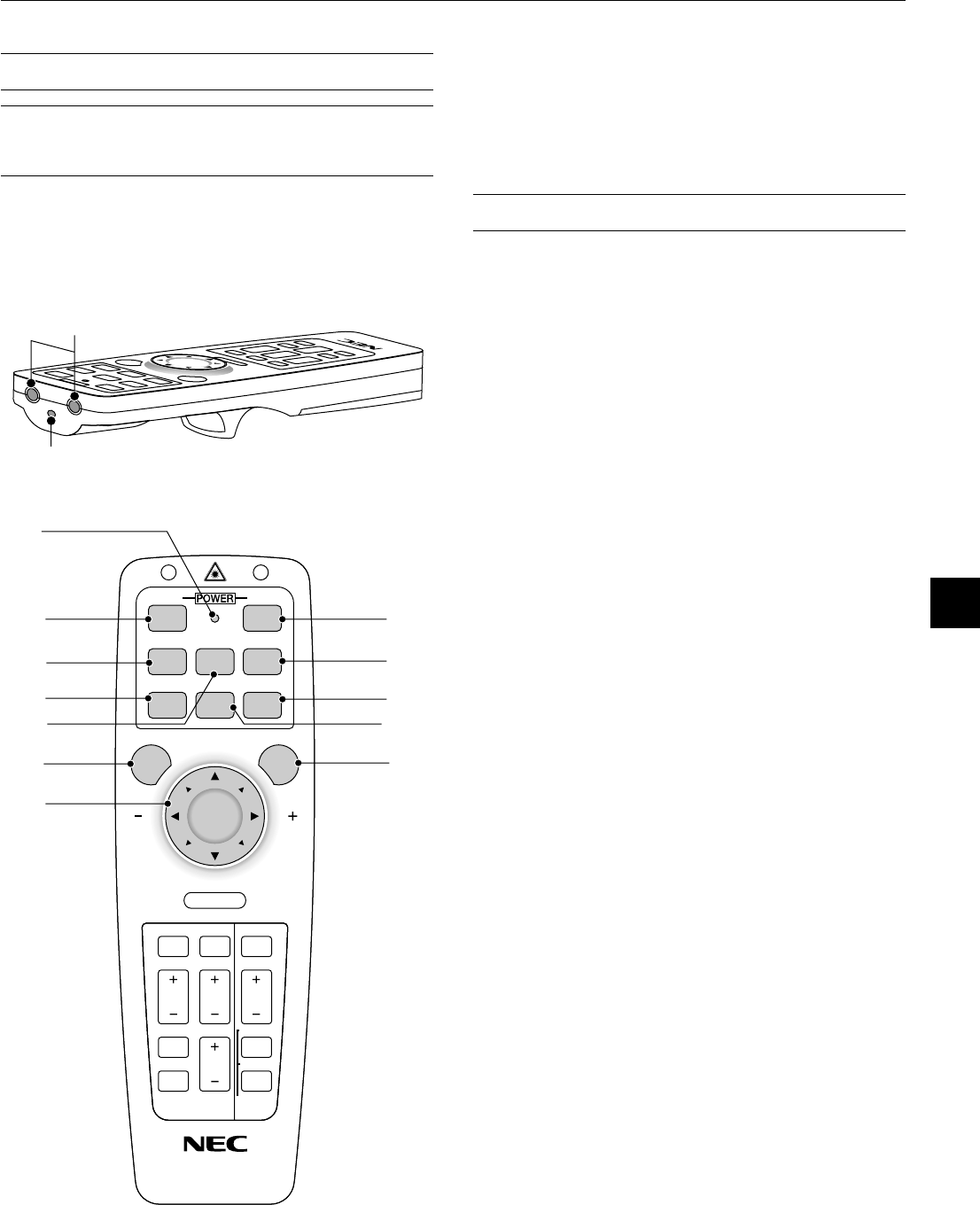
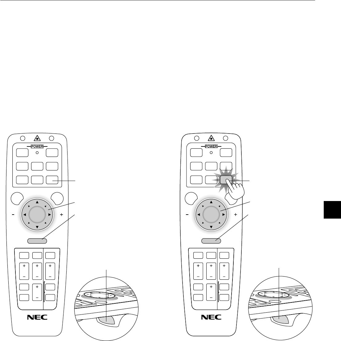
2.Turn on and off the Projector
VIDEOS
-
VIDEO
AUTO ADJ.
RGB 1
MENULASER
RGB 2P
J
ONOFF
Power ON button
M
E
N
E
N
T
E
R
C
A
N
C
E
L
SELECT
POWER
STATUS
ON
/
STAND BY
SOURCE
AUTO
ADJUST
PC CARD
ACCESS
P
C
C
O
N
T
R
O
L
V
ID
E
O
S
-V
ID
E
O
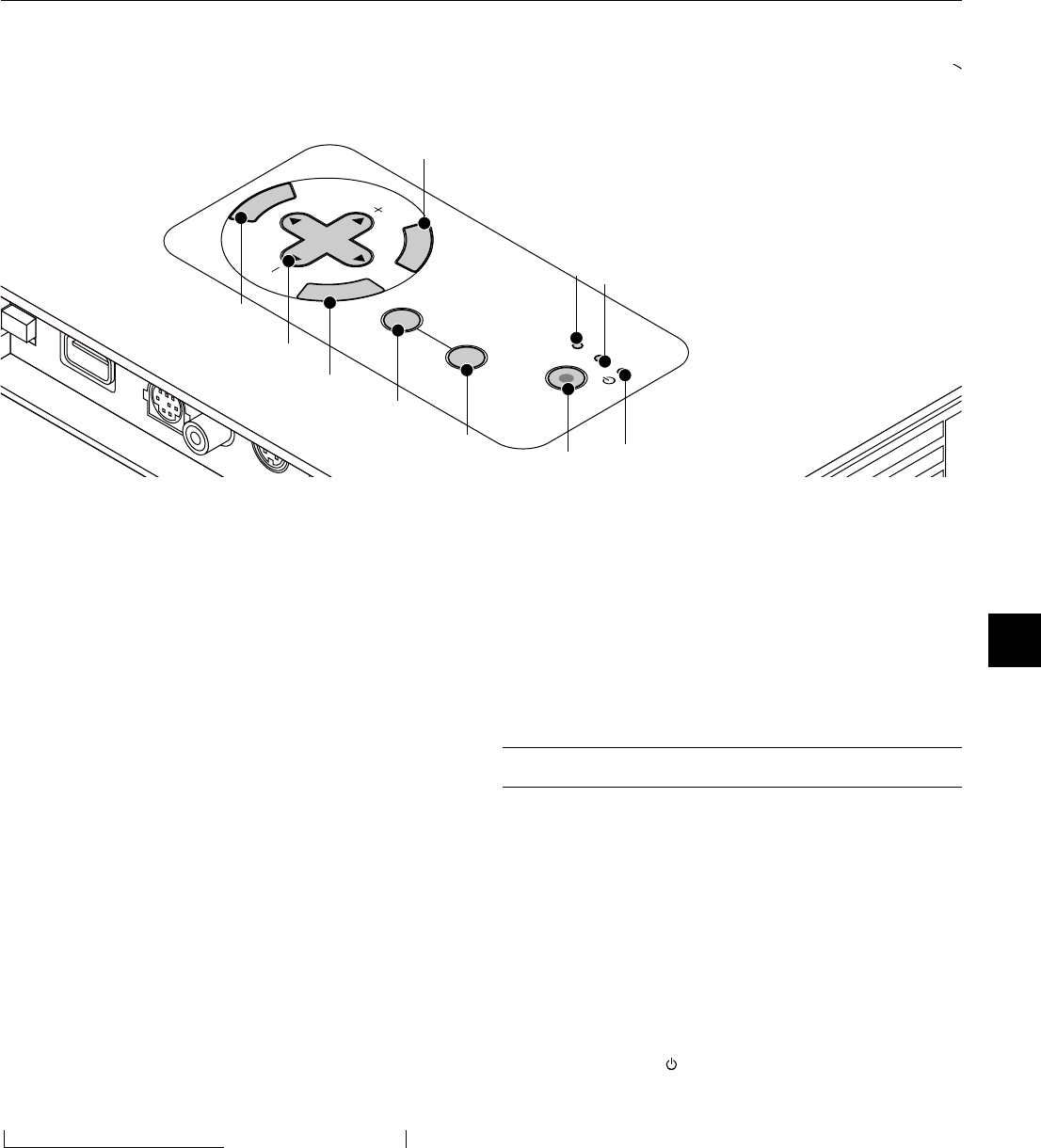
Power ON/STAND BY button
Indicator
To turn on the projector:
Only after you press the “On” button on the remote control (“ON/
STAND BY” button on the projector cabinet) will the power indicator
turn to green and the projector become ready to use.
NOTE: To turn the projector on by plugging in the power cable, use the
menu and enable the “Auto Start” feature. (See page E-38.)
NOTE: Immediately after turning on the projector, screen flicker may occur.
This is not a fault. Wait 3 to 5 minutes until the lamp lighting is stabilized.
To turn off the projector:
First press the “off” button on the remote control (“ON/STAND BY”
button on the projector cabinet) for a minimum of two seconds. The
power indicator will glow orange. After the projector turns off, the
cooling fans keep operating for one minute.
NOTE: Do not disconnect the power cable during this time. Then, unplug
the power cable. The power indicator will go out.
Status of indicator light: turn on
POWER
STATUS
POWER
STATUS
ON
/
STAND BY
POWER
STATUS
High-Bright mode:
stand by
steady orange light
flashing green light
steady green light
flashing one minute
steady light
Eco mode:
POWER
STATUS
POWER
STATUS
POWER
STATUS
ON
/
STAND BY
stand by
steady orange light
flashing green light
(High-Bright mode)
steady green light
(Eco mode)
flashing one minute
steady light
Status of indicator light: turn off
ON
/
STAND BY
POWER
STATUS
POWER
STATUS
POWER
STATUS
ON
steady green light
change to flashing
green light
steady orange light
cooling down
stand by
Press a minimum
of two seconds.
E – 25
3.Adjust a Projected Image
Select the Computer or Video Source
HELP
POINTER
PC CARD
AUTO ADJ.
VIDEOS
-
VIDEO
RGB 1RGB 2
P
J
E
N
T
E
R
C
A
N
C
E
L
SE
LECT
ON
/
STAND BY
SOURCE
AUTO
ADJUST
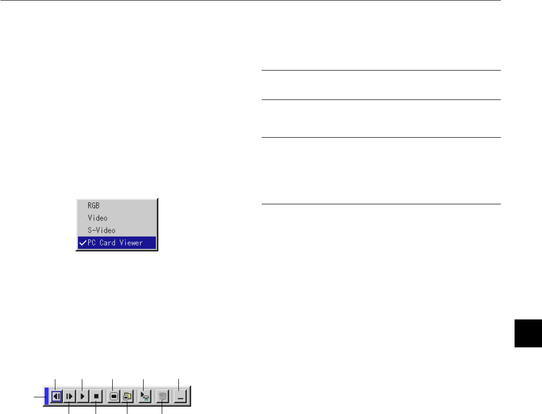
Press the Source button on the remote control or the projector cabinet
to select “Video” (VCR, document camera, or laser disc player), S-
Video”, “RGB” (computer or DVD with component output) [ “DVI digital”
, “DVI analog” (computer with DVI output: LT156 only)] or “PC Card
Viewer” (slides on a CompactFlash card) to display the image.
Or press the “Menu” button on the remote control or the cabinet and
use the menu to select your video source: “Video”, “S-Video”, “RGB
(DVI on LT156)” or “PC Card Viewer”.
NOTE: If no input signal is available, the projector will display a blue back-
ground (factory preset).
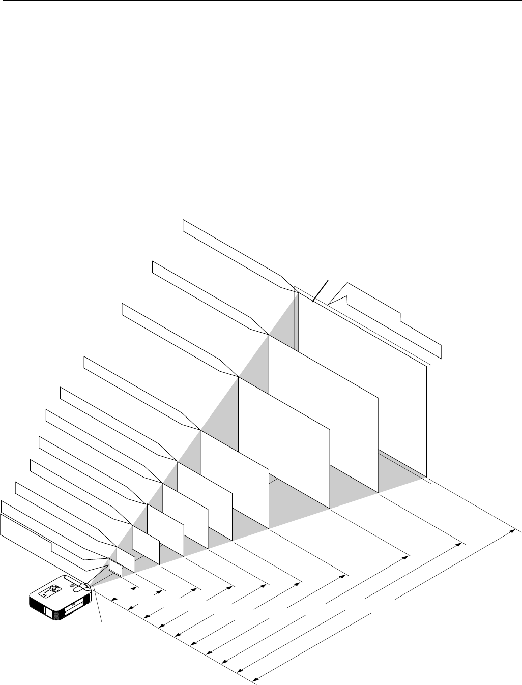
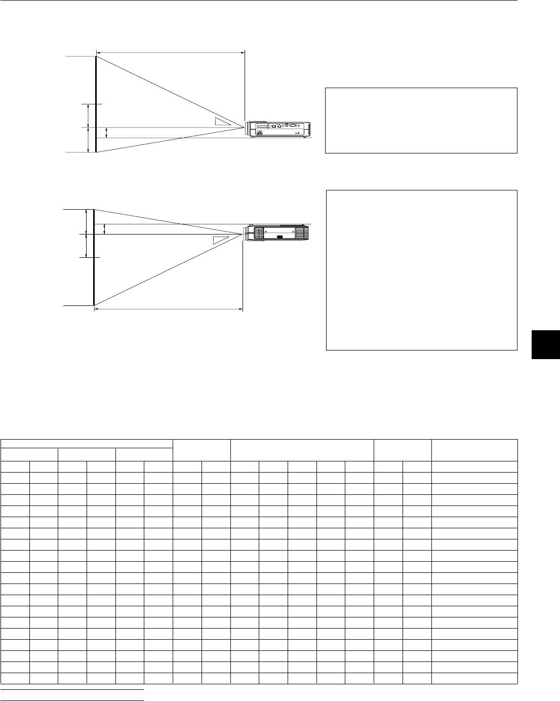
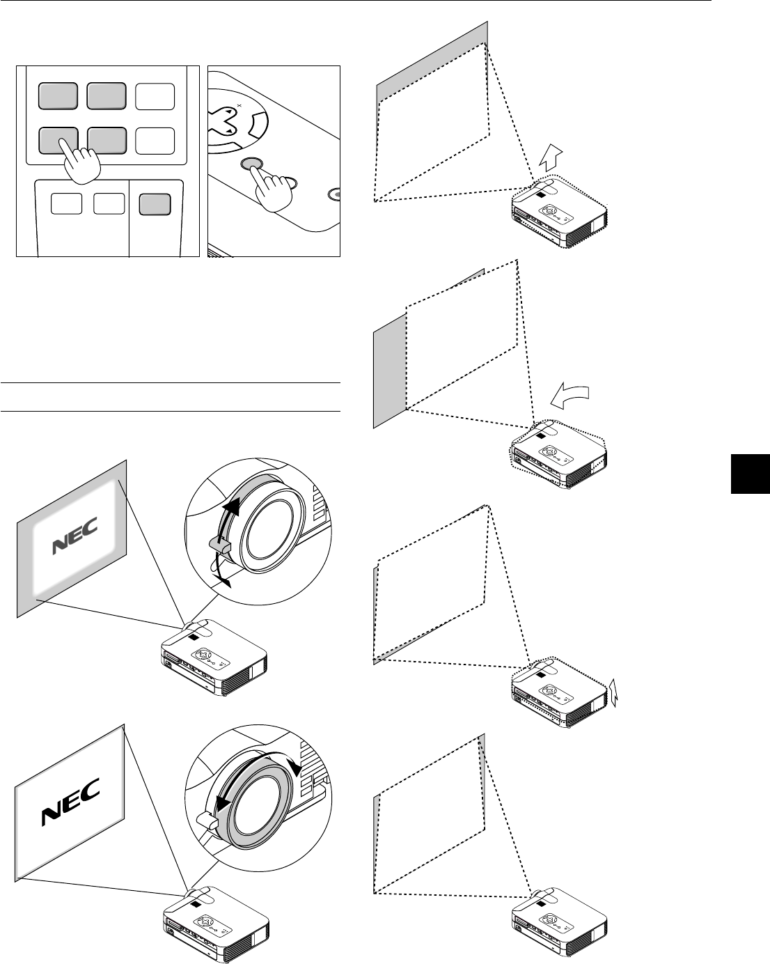
Adjust the Image Size and the Focus
Use the Zoom lever to fine adjust the image size on the screen
Use the Focus ring to obtain the best focus.
Place your projector on a flat
level surface and ensure that the
projector is square to the screen.
Lift the front edge of the projector to
center the image vertically.
Move the projector left to center
the image horizontally on the
screen.
Rotate the rear foot to make the
image square to the screen.
Use keystone correction for proper
adjustment.
E – 26
VIDEOS
-
VIDEO
AUTO ADJ.
RGB 1
MENULASER
RGB 2P
J
ONOFF
[Poor picture]
[Normal picture]
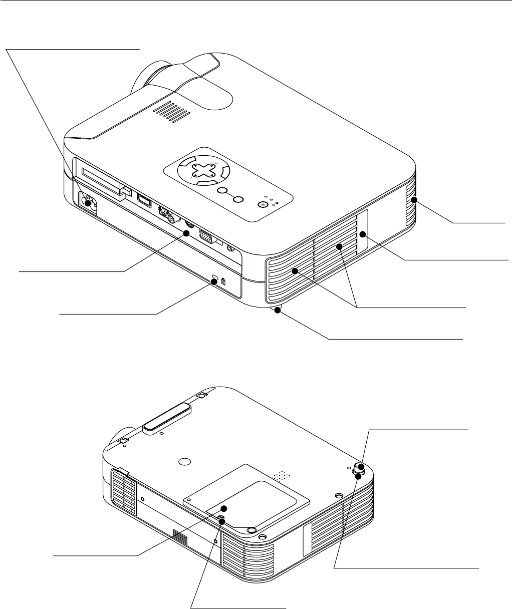
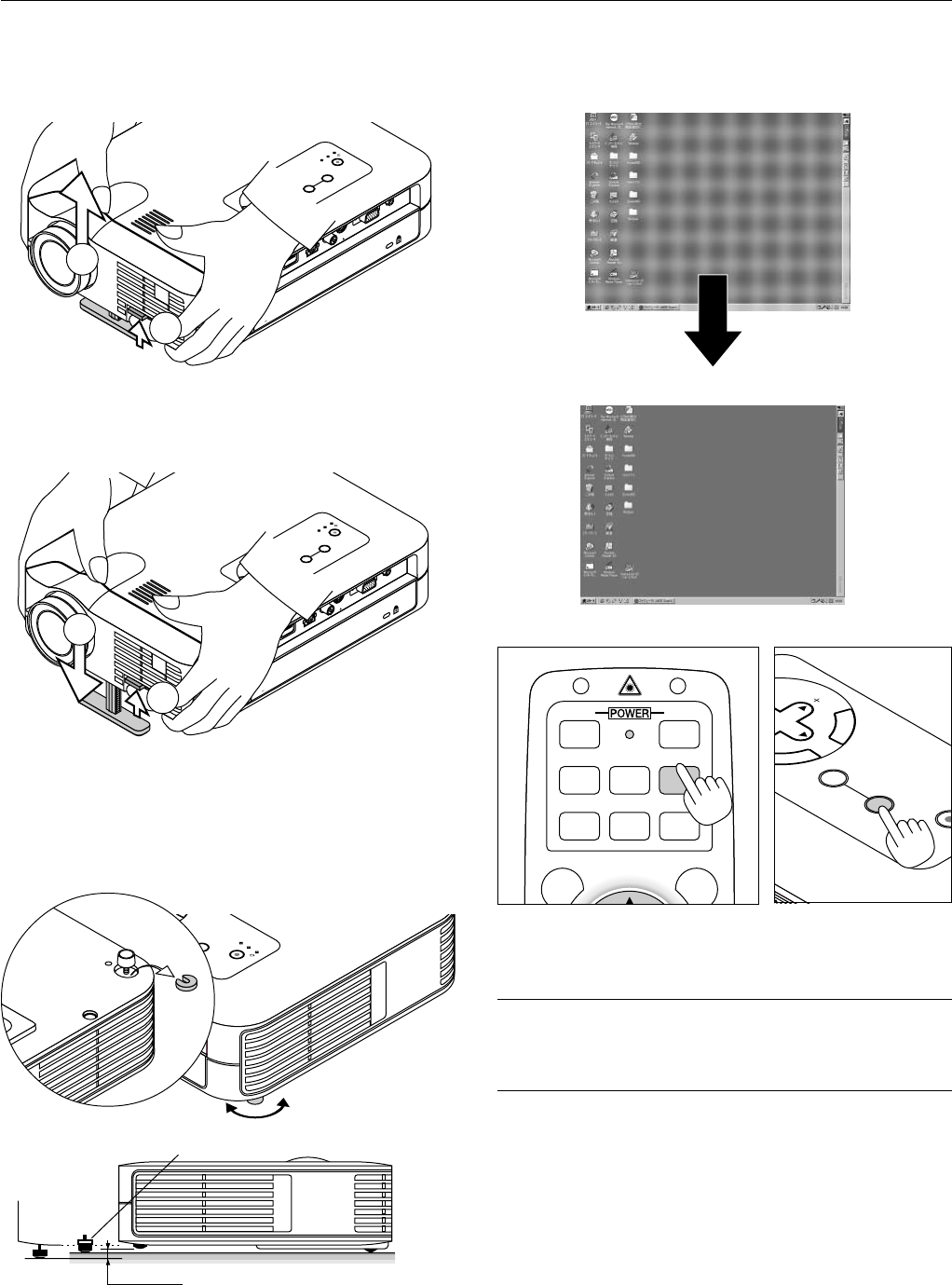
Adjust the Tilt Foot
1.Lift the front edge of the projector.
2.Press the Tilt button on the front of the projector to extend the ad-
justable tilt foot (maximum height).
M
E
N
U
E
N
T
E
R
C
A
N
C
E
L
S
E
L
E
C
T
P
O
W
E
R
S
T
A
T
U
S
O
N
/
S
T
A
N
D
B
Y
S
O
U
R
C
E
A
U
T
O
A
D
J
U
S
T
P
C
C
A
R
D
A
C
C
E
S
S
A
C
I
N
C
C
A
R
D
U
S
B
P
C
C
O
N
TR
O
L
V
ID
E
O
S
-V
ID
E
O
R
G
B
A
U
D
IO
2
1
3.Press and hold the Tilt button.
4. Lower the front of the projector to the desired height and release the
button to lock the Adjustable tilt foot.
There is approximately 10 degrees of up and down adjustment for
the front of the projector.
Do not use the tilt-foot for purposes other than originally intended.
Misuses such as gripping the tilt-foot or hanging on the wall can cause
damage to the projector.
To fine-adjust the height of the rear foot, remove the spacer (black
rubber) and rotate the rear foot to the desired height.
*If the projected image does not appear square to the screen then
use keystone correction for proper adjustment.
Adjust the Image Using Auto Adjust
The Auto Adjust function automatically optimizes the image in RGB
mode.
E
N
T
E
R
C
A
N
C
E
L
SE
LECT
ON
/
STAND BY
SOURCE
AUTO
ADJUST
Press the Auto Adjust button to adjust Position-H/V and Pixel Clock/
Phase for an optimal picture. Some signals may not be displayed cor-
rectly or take time to switch between sources.
NOTE: For LT156
*The horizontal and vertical position adjustments to DVI digital signal are not
stored in memory on LT156.
*The Pixel Clock and Phase items are not available for DVI digital signal on
LT156.
M
E
N
U
E
N
T
E
R
C
A
N
C
E
L
S
E
L
E
C
T
P
O
W
E
R
S
T
A
T
U
S
O
N
/
S
T
A
N
D
B
Y
S
O
U
R
C
E
A
U
T
O
A
D
J
U
S
T
P
C
C
A
R
D
A
C
C
E
S
S
A
C
IN
C
C
A
R
D
U
S
B
P
C
C
O
N
T
R
O
L
V
I
D
E
O
S
-
V
I
D
E
O
R
G
B
A
U
D
I
O
3
4
E
R
C
P
O
W
E
R
S
T
A
T
U
S
O
N
/
S
T
A
N
D
B
Y
S
O
U
R
C
E
A
U
T
O
A
D
J
U
S
T
P
C
C
A
R
D
A
C
C
E
S
S
G
B
A
U
D
I
O
max.
min.
16mm
Spacer
Up
Down
E – 27
Source display
Each time the Source button is pressed, the input source will change
as follows:
→ RGB [“DVI (DIGITAL) → DVI (ANALOG)” on LT156] → Video
PC Card Viewer ← S-Video ←
If no input signal is present, the input will be skipped.
Press the Auto Adjust button to fine-tune the computer image or to
remove any vertical banding that might appear and to reduce video
noise, dot interference or cross talk (this is evident when part of your
image appears to be shimmering). This function adjusts the clock fre-
quencies that eliminate the horizontal banding in the image. This func-
tion also adjusts the clock phase to reduce video noise, dot interfer-
ence or cross talk. (This is evident when part of your image appears to
be shimmering.)
This adjustment may be necessary when you connect your computer
for the first time.
NOTE: The Auto Adjust function does not work for component signal.
Basic Operation
Selecting the computer or video source:
Optimizing RGB image automatically
Press the Auto Adjust button to optimize an RGB image automatically.
SOURCE
AUTO
ADJUST
HELP
POINTER
PC CARD
AUTO ADJ.
VIDEOS
-
VIDEO
RGB 1RGB 2
P
J
SOURCE
AUTO
ADJUST
VIDEOS
-
VIDEO
AUTO ADJ.
RGB 1
MENULASER
RGB 2P
J
ONOFF
On LT156:
Press the RGB 1 button on the remote control to select DVI digital
signal and the RGB 2 button for DVI analog signal.
E – 28
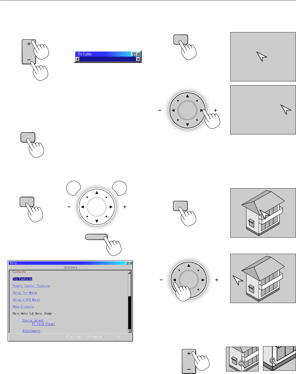
Volume control:
Sound level from the speaker on the projector can be adjusted.
increase volume
VOL.
Volume bar
decrease volume
Turning off picture and sound:
Press the Picture Mute button to turn off the image and sound for a
short period of time. Press again to restore the image and sound.
PIC
-
MUTE
Getting Help about how to operate the projector:
You get the contents about Help.
Display Help
MENULASER
R-CLICK/CANCEL
Exit Help
Using Pointer
You can use one of eight pointers to draw your audience's attention to
the portion of a projected image you want.
Press the Pointer button to
display the pointer.
Use the Select button to
move the pointer.
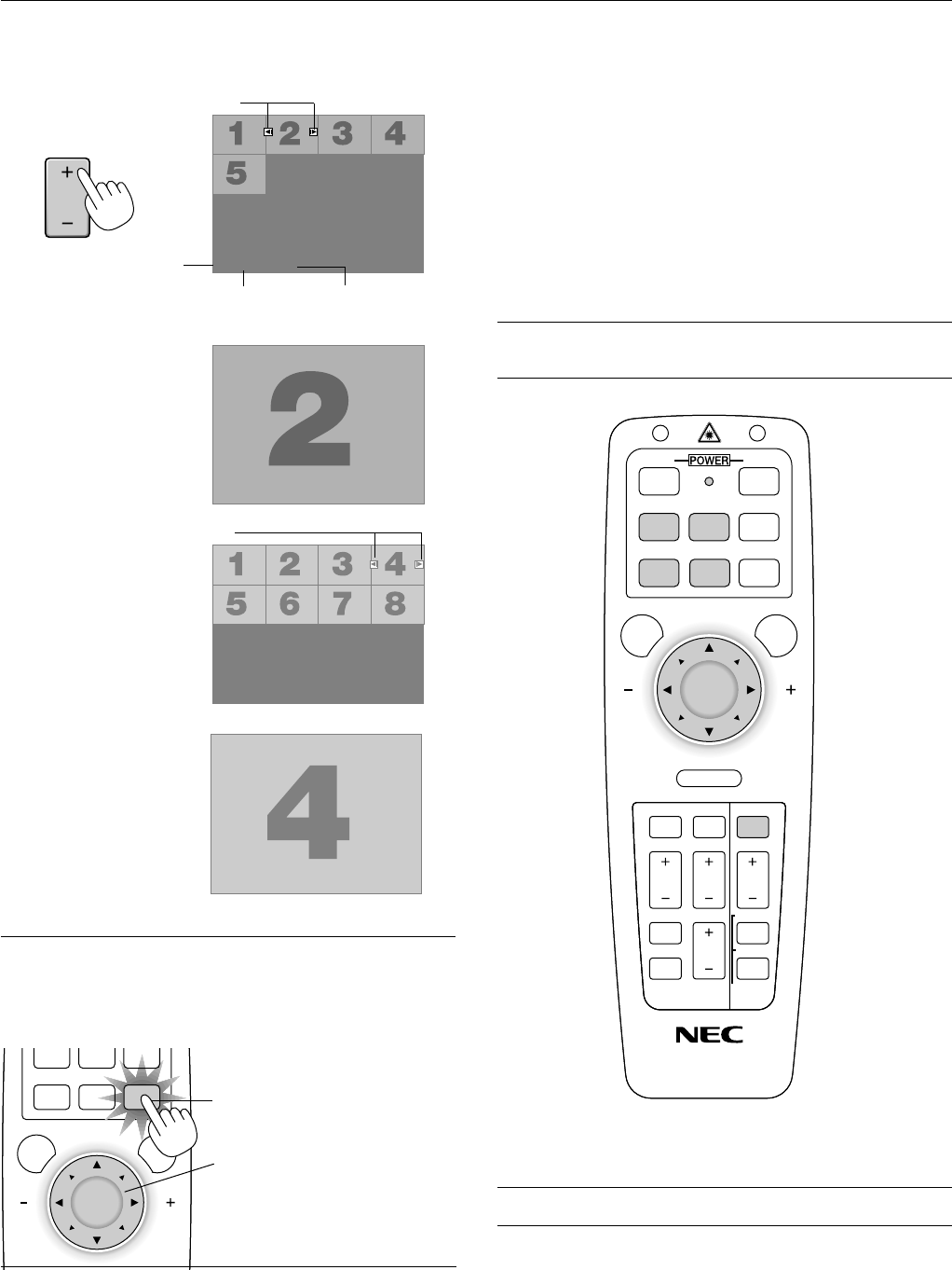
Enlarging and Moving a Picture
You can enlarge the area you want up to 400 percent.
To do so:
1.Press the Pointer button to display the pointer.
2.Move the pointer to the area you want to enlarge.
3.Enlarge the selected area.
When the Magnify (+) button is pressed, the pointer is changed to
a magnifying glass. To move the magnifying glass, use the Mouse
button.
MAGNIFY
HELP
POINTER
POINTER
E – 29
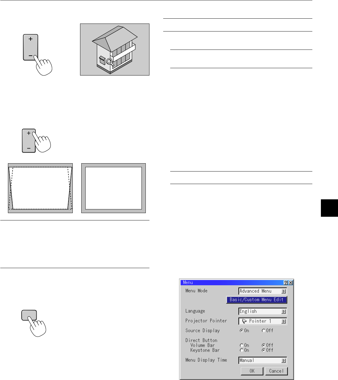
4.Return the image to the original size.
Correcting Keystone distortion
Press (+) or (-) to correct keystone (trapezoidal) distortion to make the
top or bottom of the screen longer or shorter so that the projected
image is rectangular.
KEYSTONE
NOTE: The maximum keystone angle that can be corrected is 40 degrees up-
ward and 20 degrees downward with the projector placed horizontally on the
ground plane.
Depending on the type of graphics being used, the picture may get blurred or
keystone correction may not be possible when excessive keystone correction
is used.
The idea is, the closer you are to native resolution, the better image you will
see.
Freezing a picture
Press the Freeze button to freeze a picture. Press again to resume
motion.
Keystone distortionNormal
MAGNIFY
FREEZE
Using the Menus
NOTE: The on-screen menu may not be displayed correctly while interlaced
motion video image is projected.
1.Press the “Menu” button on the remote control or projector cabi-
net to display the Main Menu.
NOTE: When using a USB mouse, click the mouse button to display the
main menu. For other operations, do the same way as you use your PC
mouse.
2.Press the ▲▼ buttons on the remote control or the projector cabi-
net to highlight the menu for the item you want to adjust or set.
3.Press the
ᮣ
button or the “Enter” button on the projector cabinet
or the “Left Click” button on the remote control to select a submenu
or item.
4.Adjust the level or turn the selected item on or off by using “Se-
lect”
ᮤ
or
ᮣ
buttons on the cabinet, or the “Mouse button” on the
remote control. The on-screen slide bar will show you the amount
of increase or decrease.
5.Changes are stored until you adjust it again.
ENTER.........Stores the setting or adjustments.
CANCEL..........
Return to the previous screen without storing settings or ad-
justments.
NOTE: You can close the main and sub menus simultaneously by pressing
the PJ button to cancel the Projector mode.
6.Repeat steps 2-5 to adjust an additional item, or press “Cancel”
on the projector cabinet or the remote control to quit the menu
display.
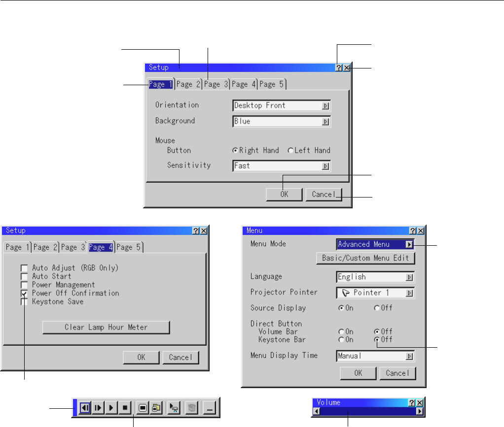
Customizing Basic/Custom Menu
The Basic/Custom menu can be customized to meet your requirements.
Selecting a menu item from the “Basic/Custom Menu Edit” list, allows
you to custom tailor the menu items to your needs.
1.Select “Basic/Custom Menu Edit” to display the “Basic/Custom
Menu Edit” screen.
E – 30
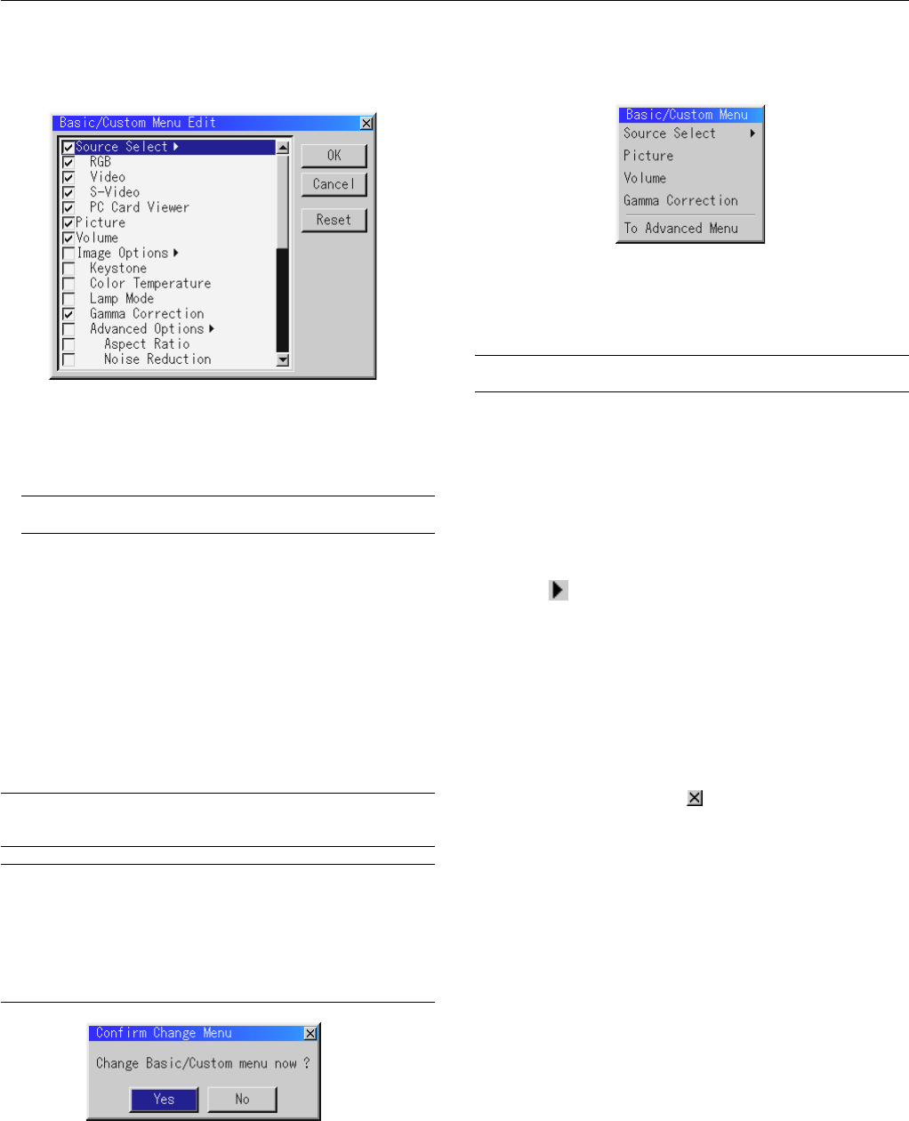
2.Use the ▲ or ▼ button to highlight your selection and press the
Enter button to place a check mark next to an option. This action
enables that feature.
Press the Enter button again to clear the check box.
If you select an item with a solid triangle
ᮣ
and press the Enter
button on the remote control or the projector cabinet, you can
enable all the items within that submenu.
Also you can turn on an item within the submenu without placing
a check mark on the main menu item.
NOTE: Up to 12 main menu items (within Basic/Custom Menu Edit, not
including submenu items) can be selected.
3.In order for the changes to take effect, use the
ᮤ
or
ᮣ
button on
the remote control or the projector cabinet to highlight “OK”,
then press the Enter button. To cancel the changes, use the ▲ or
▼ buttons to highlight “Cancel” and press the “Enter” button.
To return to the factory default, select “Reset” then press the “En-
ter” button.
The default Basic/Custom Menu items are:
Source Select (RGB [DVI (DIGITAL) / DVI (ANALOG) on LT156],
Video, S-Video and PC Card Viewer), Picture, Volume, Image Op-
tions (Keystone, Color Temperature and Lamp Mode), Projector
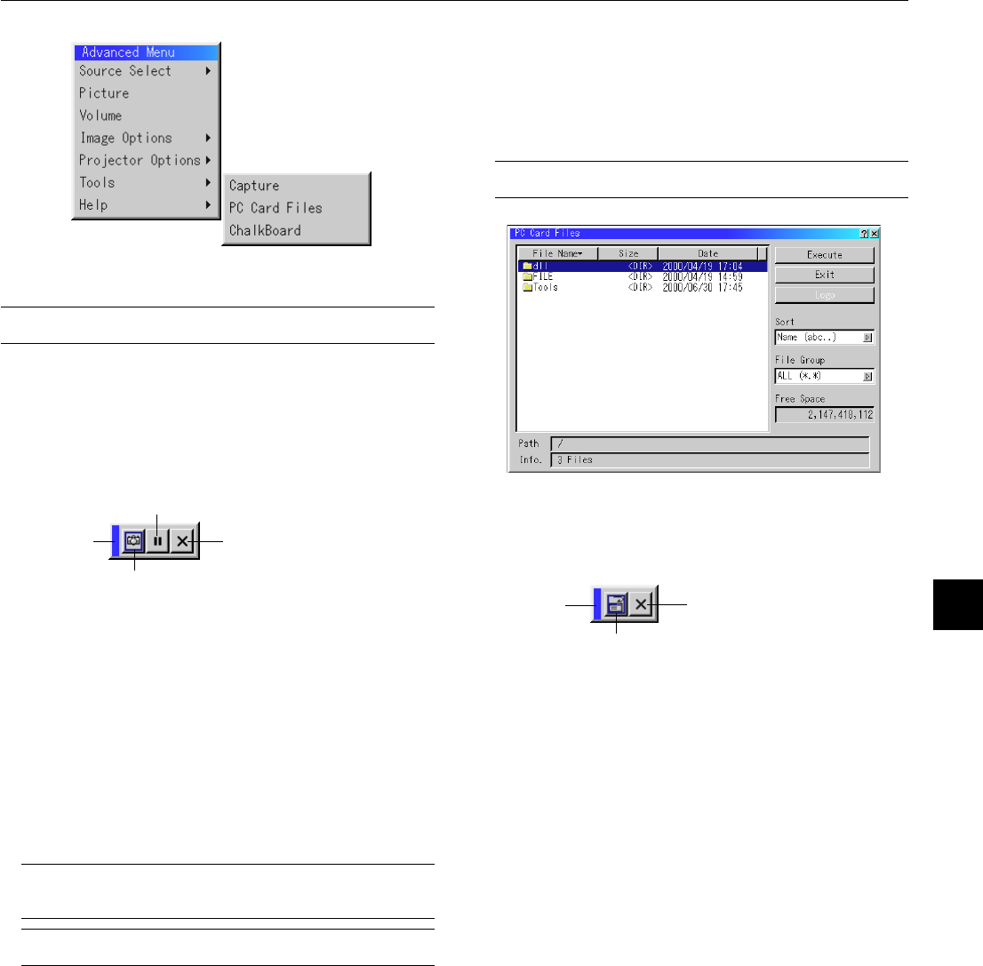
Options (Menu and Setup), Tools (Capture, PC Card Files and
ChalkBoard) and Help (Contents and Information)
NOTE: Once you have selected OK on the Basic/Custom Menu Edit screen, you
cannot cancel the changes on the Menu screen. However, you can re-edit the
menu items over again as described in the steps above.
NOTE: If the “Advanced Menu” item has been selected on the Menu mode, you
get the “Confirmation Change Menu” upon completion of “Basic/Custom Menu”
editing. In this case, selecting “Yes” then “Enter” will close all the menus and
apply the changes from the Advanced menu to the Basic/Custom Menu. If you
select “No” then “Enter” functions, then all menu items will return to the Ad-
vanced menu, but your changes will still be available within the “Basic/Custom
Menu” selection. To display the previously tailored Basic/Custom Menu, select
“Basic/Custom Menu” from the “Menu Mode”.
An item “To Advanced Menu” will be added to the bottom of the Basic/
Custom Menu.
Selecting this item and pressing the “Enter” button will display the “Ad-
vanced Menu” features.
Using a USB Mouse
Using a USB mouse gives you a smooth operation. A commercially
available USB mouse is required.
NOTE: There may be some brands of USB mouse that the projector does not
support.
Operate the Menus using the USB mouse:
Mouse Cursor:
When connecting a USB mouse to the projector, you get a mouse
cursor on the screen.
Unless you use your USB mouse within 10 seconds, the mouse
cursor disappears.
Menu Display:
Clicking with a mouse button displays the main menu.
Clicking displays the pull-down menu.
To close the menu, click anywhere in the background.
Adjusting and Setting Display:
You can select a menu item and click with a mouse button to make
adjustments and setting.
Examples:
Click (or press and hold) the mouse button
ᮤ
or
ᮣ
to adjust the
brightness.
Or click and drag the mouse button on the slide bar horizontally to
adjust it.
To save the adjustments, click . The display is closed.
If you click anywhere in the background while displaying adjust-
ment and setting menu or dialog box, you will get the main menu at
the clicking point.
E – 31
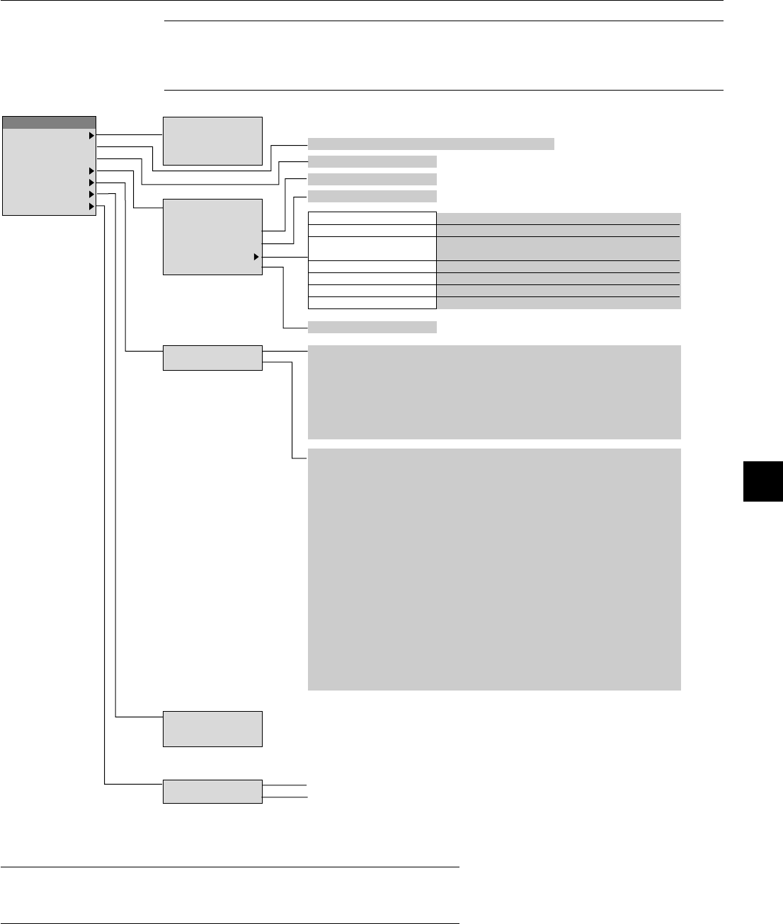
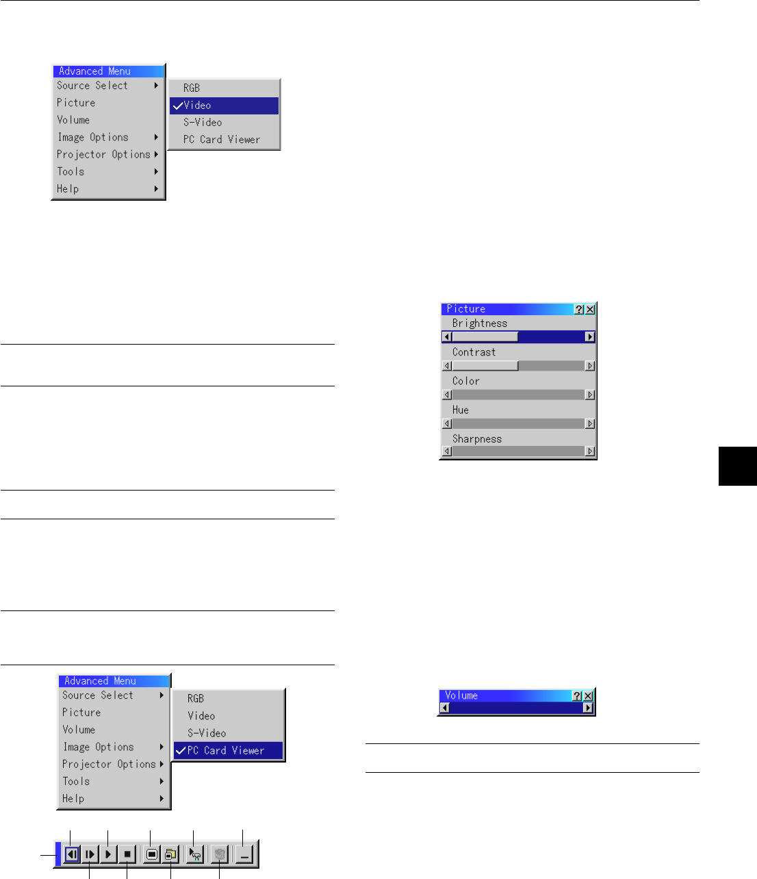
Menu Tree
Advanced Menu
Source Select
RGB
Picture
Video
Volume
S-Video
Brightness/Contrast/Color/Hue/Sharpness
Image Options
PC Card Viewer
Projector Options
Volume
High-Bright/Eco
Tools
HelpKeystone
Normal/Natural 1/Natural 2
Color Temperature
Lamp Mode
Gamma Correction
Aspect RatioNormal/Zoom/Wide Zoom/Cinema
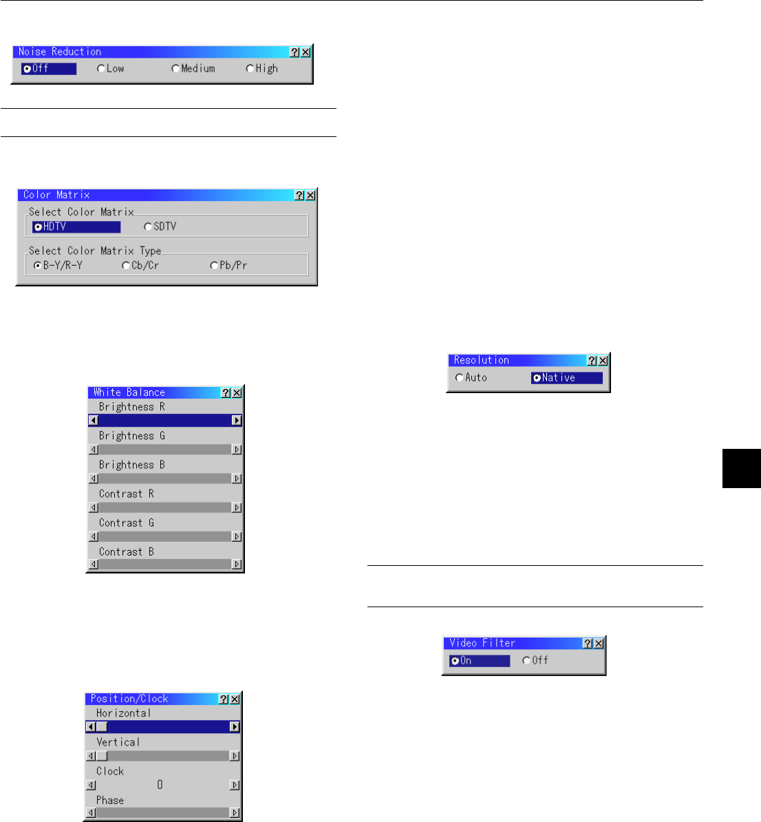
Advanced Options
Noise ReductionOff/Low/Medium/High
Factory Default
Color MatrixSelect Color Matrix: HDTV/SDTV
Select Color Matrix Type: B-Y/R-Y,Cb/Cr,Pb/Pr
White BalanceBrightness R/G/B, Contrast R/G/B
Position/ClockHorizontal/Vertical/Clock/Phase
ResolutionAuto/Native
Video FilterOn / Off
All Data/Current Signal
Menu
Setup
Menu Mode (Advanced Menu, Basic/Custom Menu)
Basic/Custom Menu Edit
Language (English/German/French/Italian/Spanish/Swedish/Japanese)
Projector Pointer (Pointer 1-8)
Source Display (On/Off)
Direct ButtonVolume Bar (On/Off)
Keystone Bar (On/Off)
Menu Display Time (Manual/Auto 5 sec/Auto 10 sec/Auto 30 sec)
Gebruikershandleiding.com neemt misbruik van zijn services uitermate serieus. U kunt hieronder aangeven waarom deze vraag ongepast is. Wij controleren de vraag en zonodig wordt deze verwijderd.
Product:
Spelregels forum
Om tot zinvolle vragen te komen hanteren wij de volgende spelregels:
lees eerst de handleiding door;
controleer of uw vraag al eerder door iemand anders is gesteld;
probeer uw vraag zo duidelijk mogelijk te stellen;
heeft u een probleem en al geprobeerd om dit op te lossen, vermeld dit erbij aub;
heeft u een oplossing gekregen van een bezoeker dan horen wij dat graag in dit forum;
wilt u een reactie geven op een vraag of antwoord, gebruik dan niet dit formulier maar klik op de knop 'reageer op deze vraag';
uw vraag wordt direct op de website gezet; vermijd daarom persoonlijke gegevens in te vullen;
Belangrijk! Als er een antwoord wordt gegeven op uw vraag, dan is het voor de gever van het antwoord nuttig om te weten als u er wel (of niet) mee geholpen bent! Wij vragen u dus ook te reageren op een antwoord.
Belangrijk! Antwoorden worden ook per e-mail naar abonnees gestuurd. Laat uw emailadres achter op deze site, zodat u op de hoogte blijft. U krijgt dan ook andere vragen en antwoorden te zien.
Abonneren
Abonneer u voor het ontvangen van emails voor uw Nec LT155 bij:
nieuwe vragen en antwoorden
nieuwe handleidingen
U ontvangt een email met instructies om u voor één of beide opties in te schrijven.
Ontvang uw handleiding per email
Vul uw emailadres in en ontvang de handleiding van Nec LT155 in de taal/talen: Engels als bijlage per email.
De handleiding is 1,63 mb groot.
U ontvangt de handleiding per email binnen enkele minuten. Als u geen email heeft ontvangen, dan heeft u waarschijnlijk een verkeerd emailadres ingevuld of is uw mailbox te vol. Daarnaast kan het zijn dat uw internetprovider een maximum heeft aan de grootte per email. Omdat hier een handleiding wordt meegestuurd, kan het voorkomen dat de email groter is dan toegestaan bij uw provider.
Uw handleiding is per email verstuurd. Controleer uw email
Als u niet binnen een kwartier uw email met handleiding ontvangen heeft, kan het zijn dat u een verkeerd emailadres heeft ingevuld of dat uw emailprovider een maximum grootte per email heeft ingesteld die kleiner is dan de grootte van de handleiding.
Er is een email naar u verstuurd om uw inschrijving definitief te maken.
Controleer uw email en volg de aanwijzingen op om uw inschrijving definitief te maken
U heeft geen emailadres opgegeven
Als u de handleiding per email wilt ontvangen, vul dan een geldig emailadres in.
Uw vraag is op deze pagina toegevoegd
Wilt u een email ontvangen bij een antwoord en/of nieuwe vragen? Vul dan hier uw emailadres in.