543213
1
Verklein
Vergroot
Pagina terug
1/74
Pagina verder
1
ITALIANO
INDICE
Introduzione .......................................................................................... 2
Descrizione comandi ............................................................................ 3
Installazione.......................................................................................... 7
Collegamento elettrico ....................................................................... 7
Installazione dell’antenna .................................................................. 7
Uso dell’ALAN 48 EXCEL MULTI .........................................................8
Selezione bande di frequenza ........................................................... 8
Tabella bande di frequenza................................................................ 8
Caratteristiche tecniche ........................................................................9
Informazione importante
Aggiornamenti sulle restrizioni nazionali:
Per poter utilizzare tale apparato in Belgio, Gran Bretagna, Spagna e
Svizzera i residenti necessitano di una licenza individuale; coloro che
provengono dall’estero invece, godono di libero uso per la FM, mentre
per l’ AM devono essere in possesso della licenza del paese d’origine.
Per gli stranieri che arrivano in Italia, è necessaria un’autorizzazione
Italiana.
L’Austria invece non autorizza l’utilizzo di ricetrasmettitori CB multi-
standard (programmabili). Si consiglia di rispettare scrupolosamente
questa direttiva e di non utilizzare l’apparato in territorio austriaco.
Lungo i conni di alcune zone della Germania, l’utilizzo come stazione
base dal canale 41 all’80 non è ammesso. Rivolgersi all’ufcio notiche
locale per ulteriori dettagli. Aggiornamenti sulle restrizioni all’uso in
vigore in Germania vengono costantemente pubblicati sul website
ALAN-Albrecht www.alan-albrecht.info.
22
ALAN 48 EXCEL MULTI è un ricetrasmettitore veicolare la cui
caratteristica principale è la possibilità di selezionare qualsiasi banda
CB europea tramite una semplice ed immediata procedura. ALAN 48
EXCEL MULTI è inoltre dotato del dispositivo “ESP2” (soppressore
dinamico dei disturbi) che permette di ridurre notevolmente i disturbi
audio (no al 95%) facilitando l’ascolto anche quando il segnale è
disturbato.
L’ampio display multifunzionale permette la visualizzazione del numero
del canale in uso o della frequenza corrispondente ed è retroilluminato
per una comoda visualizzazione notturna. ALAN 48 EXCEL MULTI
è dotato inoltre uno strumento S-Meter analogico per una comoda
visualizzazione della potenza trasmessa e del segnale ricevuto e
novità assoluta dispone anche di un riduttore interno di tensione
che ne permette l’uso con doppia alimentazione, 13.2V e 24V.
L’apparato viene consegnato secondo la banda “EC“ CEPT 40CH FM
4W.
3
ITALIANO
DESCRIZIONE COMANDI
1. Selettore canali: permette la selezione manuale dei canali.
2. Presa microfono: inserire lo spinotto microfonico in questa presa.
3. Indicatore: questo strumento indica l’intensità dei segnali in ricezione e la potenza
di uscita RF del trasmettitore.
4. Display retroilluminato multifunzione
a. Numero canali selezionati (da 1 a 40) o frequenza corrispondente.
b. Attivazione tasto FUNC.
c. ESP: attivazione soppressore dinamico dei disturbi.
d. DW: funzione DUAL WATCH attivata
e. EMG: indicatore attivazione canale 9 / 19 o canale in uso
f. LOCK: indicatore funzione blocco tasti e selettori attivata
g. SCAN: indicatore funzione SCAN attivata
h. M1-M2-M3-M4-M5: indicatori memorie canali .
i. Indica la banda di frequenza selezionata.
j. Viene visualizzato quando la radio trasmette in bassa potenza (condizione che si
verica solo per determinate bande di frequenza – vedi tabella bande)
N.K.M5
LOCK
M4/LCR
AM/FM
M3
SCAN
M2
DW
M1
EMG
FUNC
01
3
5
7
9
30
2
3
5
10
0
POWER
MIC
CH
VOL
SQ
MIC
RF
TX RX AM FM
CB/PA
1
2
3 4567
8 9 10 11 12 13 14
16
18
15
17
F
EMG DWESP LOCK SCANLOW
a
b
ecfdg
i
j
h
F
EMGDWESP LOCK SCANLOW
44
5. Indicatore “AM/FM”
Indica il modo operativo. FM: LED rosso; AM: LED verde.
6. Indicatore “RX/TX”
Indicatore di ricezione / trasmissione. Posizione RX: LED verde; posizione TX: LED
rosso.
7. Selettore “CB - PA”
Posizione “CB: in questa posizione, l’apparato é attivo come ricetrasmettitore.
Posizione PA”: questo modo di funzionamento é possibile solo se viene collegato
un altoparlante alla presa PA sul retro (scritta “PA” visualizzata sul display). In questo
caso, il comando “MIC” viene usato come controllo dell’amplicazione.
8. Tasto FUNC
Questo tasto permette, a scelta dell’utente, di:
• visualizzare il canale o la frequenza operativa premendo “FUNC” per circa 3
secondi.
• attivare le seconde funzioni dei tasti “M” (M1/M5).
M1 / M2 / M3 / M4 / M5:
La radio ha la possibilità di memorizzare e di richiamare all’occorrenza 5 canali a
piacimento precedentemente memorizzati. Per memorizzarne uno, procedere come
segue:
A) Selezionare il canale che si desidera memorizzare tramite il selettore canali o i
tasti “UP/DN” sul microfono;
B) Premere il tasto “FUNC”: il display mostrerà una “F”;
C) Tenere premuto per circa tre secondi il tasto “M1/EMG”: la radio emetterà un
“BIP” e il display mostrerà la scritta “M1”.
Per memorizzare altri canali ripetere i punti A e B e selezionare una diversa
memoria.
Per richiamare un canale precedentemente memorizzato premere il tasto “FUNC” e
di seguito il tasto della memoria desiderata.
I tasti di memorizzazione canali hanno una doppia funzione; qui di seguito sono
descritte le 2 modalità di funzionamento.
9. Pulsante “M1 - EMG”
Permette di memorizzare la memoria numero 1 e di richiamare i canali di emergenza.
La pressione del tasto “M1/EMG” seleziona ciclicamente il canale 9, 19 ed il canale
in uso.
10. Pulsante “M2 - DW”
Permette la memorizzazione della memoria numero 2 e l’attivazione della funzione
DUAL WATCH, che consiste nel rimanere sintonizzati contemporaneamente su due
canali a scelta dell’utente.
Con tale funzione si monitorizzerà ciclicamente un secondo canale. In presenza di un
segnale sul secondo canale, la conversazione sul canale prescelto si interromperà
e il ricevitore commuterà automaticamente sul secondo canale. Il monitoraggio
riprenderà dopo 5 secondi dal cessare del segnale.
Per attivare questa funzione, operare come segue:
- Selezionare il canale desiderato mediante il selettore canali o i tasti “UP/DN” sul
microfono;
- Premere il tasto “DW” per circa 3 secondi: la radio emetterà un “BIP” e sul display
lampeggerà la scritta “DW”.
- Selezionare il secondo canale desiderato tramite il selettore canali o i tasti “UP/
DN” sul microfono;
5
ITALIANO
- Premere nuovamente il tasto “DW” per 3 secondi circa: la radio emetterà un ‘BIP’,
il display mostrerà la scritta “DW” permanente e visualizzerà alternativamente i
due canali selezionati.
11. Pulsante “M3 - SCAN”
Tramite questo tasto, si memorizza la memoria numero 3 e si attiva la funzione
“SCAN” (ricerca automatica di un canale occupato).
Per attivare questa funzione, operare come segue:
- selezionare un canale libero e ruotare la manopola dello squelch in senso orario
in modo che il rumore di fondo scompaia;
- premere il tasto “M3/SCAN”: il display mostrerà la scritta “SCAN” ed il
ricetrasmettitore scansionerà automaticamente e ripetutamente tutti i canali no
a quando non troverà un canale in uso.
La funzione “SCAN” può essere annullata in tre modi: premendo il tasto PTT,
ruotando il selettore canali o premendo un qualsiasi tasto.
12. Pulsante “M4/LCR - AM/FM”
Questo tasto, permette la memorizzazione della memoria numero 4 e la selezione
del modo operativo (AM/FM). Modo AM: spia 5 di colore verde; Modo FM: spia 5 di
colore rosso. Se inoltre si seleziona una banda di frequenza che opera solamente
la modalità FM, il tasto AM/FM” attiva la funzione LCR (richiamo ultimo canale
utilizzato).
13. Pulsante “M5 - LOCK”
Permette di memorizzare la memoria numero 5 e di attivare la funzione “LOCK”
(blocco tastiera, selettore canali e tasti “UP/DOWN” del microfono per evitare
accidentali pressioni dei tasti).
14. Tasto “N.K.”
Tasto di attivazione del soppressore dinamico dei disturbi (Vedi introduzione).
15. Manopola “MIC”
L’amplicazione della voce in trasmissione va regolata tramite questa manopola.
Il livello ottimale della modulazione va ricercato chiedendo conferma a chi riceve la
trasmissione.
16. Manopola “RF”
Controllo della sensibilità in ricezione. Ruotando la manopola in senso orario, si
ottiene un aumento della sensibilità; ruotandola in senso antiorario, si ottiene una
diminuzione della sensibilità.
17. Manopola “VOL”
Questa manopola permette l’accensione dell’apparecchio e la regolazione del
volume al livello desiderato.
18. Manopola “SQ”
Permette la regolazione del livello di soglia della ricezione. Per la massima sensibilità
del ricevitore, é preferibile che il comando sia regolato solo al preciso livello dove il
rumore di fondo del ricevitore viene eliminato.
66
PANNELLO POSTERIORE
19. Connettore antenna: è previsto il connettore SO 239.
20. Presa S.METER: permette il collegamento di uno strumento esterno.
21. Presa PA: tramite il collegamento ad un altoparlante esterno, permette di utilizzare
l’apparato come amplicatore audio.
22. Presa EXT: presa altoparlante esterno (questo collegamento esclude l’uso dell’alto-
parlante interno).
23. POWER 13.2 Vcc: presa di alimentazione.
MICROFONO
1. Pulsante di trasmissione.
2. Pulsanti UP/DOWN:selezione canali verso
l’alto (up) e verso il basso (DN).
3. Connettore microfonico 6 pin.
UP
DOWN
2
1
3
19 20 21 22
23
ANTENNA
S-METER
PA EXT
7
ITALIANO
INSTALLAZIONE
Ricercare e localizzare, sul mezzo mobile, la posizione per installare lapparato,
utilizzando la staffa di supporto in dotazione. Tale posizionamento deve essere fatto in
modo da non creare intralcio a chi guida, ma deve anche essere facil mente accessibile.
Praticare i fori (diametro di circa 3 mm.) nella carrozzeria per il ssaggio con le viti.
Posizionare l’apparato nella staffa di ssaggio. Controllare che le viti siano ben serrate,
in considerazione delle notevoli e vibrazioni create dal mezzo mobile.
COLLEGAMENTO ELETTRICO
Prima di procedere in questa operazione, controllare che il ricetrasmettitore sia spento
(manopola del volume completamente girata a sinistra, dopo lo scatto).
Lapparato é dotato di un cavetto di alimentazione bicolore con un portafusibile inserito
sul cavo rosso (positivo). Nel collegamento, è molto importante rispettare la polari
anche se l’apparato é protetto contro l’inversione accidentale. Di norma si identica il
polo positivo con il colore rosso o con il segno ‘’+’’, e il polo negativo con il colore nero
o con il segno “-”.
Gli stessi segni (o colori) identicativi li troveremo sulla batteria (accumulatore od altro)
e nella scatola dei fusibili dell’automobile. Si raccomanda di collegare in modo corretto
e stabile i terminali del cavetto alla batteria.
ATTENZIONE
Per l’ottimizzazione delle prestazioni si consiglia l’installazione
dell’apparecchiatura in luoghi che possano consentire un sufciente riciclo
d’aria.
INSTALLAZIONE DELL’ ANTENNA
Informazioni utili :
1) Installare l’antenna nella parte più alta del veicolo.
2) Maggiore é la lunghezza dell’ antenna, migliore sarà il suo rendimento.
3) Se possibile, installare l’antenna al centro della supercie metallica scelta.
4) Tenere il cavo dell’ antenna lontano da fonti di disturbi elettrici.
5) Assicurarsi di avere una buona massa.
6) Evitare danni ai cavi.
Attenzione: non usare mai la radio CB senza aver installato un’ antenna appropriata
per non correre il rischio di danneggiare il trasmettitore; per la stessa ragione con-
trollare periodicamente il ROS.
88
USO DELL ALAN 48 EXCEL MULTI
Dopo aver installato il vostro CB e la vostra antenna, seguire attentamente le istruzioni
qui sotto riportate per ottenere un funzionamento soddisfacente del vostro apparato.
1) Avvitare la spina nella presa del microfono sul pannello.
2) Assicurarsi che l’antenna sia collegata al connettore dell’ antenna.
3) Assicurarsi che il comando di squelch sia completamente ruotato verso sinistra.
4) Accendere l’apparato e regolare il comando del volume per un buon livello sonoro.
5) Selezionare il canale desiderato, tramite il selettore canali o i tasti “UP / DOWN” del
microfono.
6) Per trasmettere, premere il pulsante di trasmissione PTT sul microfono.
7) Per ricevere, rilasciarlo.
SELEZIONE BANDE DI FREQUENZA
La scelta delle bande di frequenza deve essere eseguita a seconda del paese nel quale
si intende operare.
Procedimento:
1. Spegnere la radio.
2. Accendere l’apparecchio premendo il tasto “N.K.”.
3. Ruotare la manopola “CHANNEL” e selezionare la banda di frequenza desiderata
(vedi tabella bande).
4. Premere il tasto “LOCK” per terminare la selezione.
NOTA: Se si seleziona una banda di frequenza che opera solamente la modalità FM, il
tasto “AM/FM” attiva la funzione LCR (richiamo ultimo canale selezionato).
NOTA: Nella banda di frequenza UK, è possibile selezionare direttamente la banda
EC premendo il tasto “LCR-A/F” per 2 secondi circa.
TABELLA BANDE DI FREQUENZA
Sigla sul display Paese
I Italia 40 CH AM/FM 4Watt
I2 Italia 34 CH AM/FM 4Watt
D Germania 80 CH FM 4Watt / 12 CH AM 1 Watt
D2 Germania 40 CH FM 4Watt / 12 CH AM 1 Watt
D3 Germania 80 CH FM 4Watt / 40 CH AM 1 Watt
EU Europa 40 CH FM 4Watt / 40 CH AM 1 Watt
EC CEPT 40 CH FM 4Watt
E Spagna 40 CH AM/FM 4Watt
F Francia 40 CH FM 4Watt / 40 CH AM 1 Watt
PL Polonia 40 CH AM/FM 4W
UK Inghilterra 40 CH FM 4Watt frequenze inglesi +
+ EC 40 CH FM 4Watt frequenze CEPT
ATTENZIONE:
Lo standard sicuramente riconosciuto in tutti i paesi europei è 40CH FM 4W (EC)
Vedi tabella “Restrizioni all’uso”
9
ITALIANO
CARATTERISTICHE TECNICHE
Generali
Canali ................................................................................... 40 FM (vedi tabella bande)
Gamma di frequenza ................................................................. 26.565 - 27.99125 MHz
Controllo di frequenza ...........................................................................................a PLL
Temperatura ................................................................................................ -10° / +55°C
Tensione di alimentazione .................................................................13.2/24 Vcc ±15%
Dimensione...........................................................................150(L) x 45(A) x 175(P)mm
Peso ........................................................................................................................1 Kg.
Ricevitore
Sistema ricevente ................................................ Supereterodina a doppia conversione
Frequenza intermedia...........................................................................I° IF:10.695 MHz
...................................................................................................................II° IF:455 KHz
Sensibilità ......................................................................... 0.5µV per 20dB SINAD in FM
..........................................................................................0.5µV per 20dB SINAD in AM
Potenza d‘ uscita audio @10% THD ..................................................... 2.0 W @ 8 Ohm
Distorsione audio ........................................................................Meno dell‘ 8% @ 1KHz
Reiezione alle immagini..........................................................................................65 dB
Selettività sul canale ...............................................................................................65 dB
Rapporto segnale disturbo .....................................................................................45 dB
Assorbimento all’ attesa ...........................................................................13.2V: 450mA
.....................................................................................................................24V: 520 mA
Trasmettitore
Potenza d’uscita ............................................. duty cycle 10% 4W AM/FM @ 13.2 Vcc
Modulazione ...................................................................................... AM:da 85% a 95%
..................................................................................................... FM:1,8 KHz ± 0,2 KHz
Frequenza di risposta .............................................................................400 Hz ÷ 3 KHz
Impedenza d’ uscita .....................................................................RF 50 Ohm sbilanciato
Rapporto segnale disturbo ............................................................................. 40 dB MIN
Corrente assorbita ................................. 13.2V: 1300mA (potenza senza modulazione)
................................................................... 24V: 1600mA (potenza senza modulazione)
Le speciche sono soggette a variazione senza preavviso.
1
ENGLISH
INDEX
Introduction ........................................................................................... 2
Function and location of the controls .................................................... 3
Installation ............................................................................................ 7
Power supply ..................................................................................... 7
Installing an antenna.......................................................................... 7
How to use your ALAN 48 EXCEL MULTI ............................................8
Frequency band selection.................................................................. 8
Frequency band chart ........................................................................ 8
Specications ....................................................................................... 9
Important Note
Following national regulations have been modied:
Residents of Belgium, Great Britain, Spain and Switzerland need a
CB licence in their countries, while visitors may use their CB radios in
FM free of licence, for AM they should be able to present their home-
country’s licence document. In Italy, even visitors need a valid Italian
authorization.
Austria does not accept any multi-standard or programmable CB radio.
Please respect this requirement and do not use Your radio during driving
through Austria.
In Germany transmitting as a base station on channels 41-80 is restricted
in some areas along the country borders. No restrictions apply for
mobile use. More details can be obtained from the local RegTP authority
ofce.
Changes in European or national regulations will be published on the
service website of ALAN-Albrecht under www.alan-albrecht.info
22
ALAN 48 EXCEL MULTI is a mobile transceiver whose main feature is
the possibility to select any of the European CB bands with an easy and
quick operation. ALAN 48 EXCEL MULTI is equipped with the “ESP2”
(noise reducer device) that reduces considerably the audio noises
up to 95%, allowing a clear communication even when the signal is
disturbed.
The wide multifunctional backlit display shows the number of the channel
in use or the correspondent frequency even in conditions of deep
darkness. ALAN 48 EXCEL MULTI is also equipped with an analogical
S-Meter, showing the transmitted power and the signal received, and
with the exclusive internal voltage reducer allowing the use with 12V or
24V power supply.
The unit is preset at the factory on the “EC“band , CEPT 40CH FM 4W.
3
ENGLISH
FUNCTION AND LOCATION OF THE CONTROLS
FRONT PANEL
1. Channel selector: it permits the manual channel selection.
2. Microphone jack: insert the mic connector into this jack.
3. Indicator: this meter indicates the receiving signal strength and the transmitter RF
output power.
4. Multifunction backlighted display.
It shows:
a. channel selected number (from 1 up 40) or operative frequency
b. FUNC button activated
c. ESP: reducing noise device activated
d. DW: Dual Watch function activated
e. EMG: indicates channel being used or when the emergency channels are
activated
f. LOCK: keyboard lock function activated
g. SCAN function activated
h. M1-M2-M3-M4-M5: memory channel indicator
i. Indicates the frequency band selected.
j. It appears when the radio transmits in low power (this condition happens only in
certain frequency bands – see the chart at the end of this manual).
N.K.M5
LOCK
M4/LCR
AM/FM
M3
SCAN
M2
DW
M1
EMG
FUNC
01
3
5
7
9
30
2
3
5
10
0
POWER
MIC
CH
VOL
SQ
MIC
RF
TX RX AM FM
CB/PA
1
2
3 4567
8 9 10 11 12 13 14
16
18
15
17
F
EMG DWESP LOCK SCANLOW
a
b
ecfdg
i
j
h
F
EMGDWESP LOCK SCANLOW
44
5. AM/FM” Indicator
It indicates the operative mode. FM: red LED; AM: green LED.
6. “RX/TX” Indicator
LED indicating receiving or trasmitting mode. RX: green LED; TX: red LED.
7. “CB/PA” Selector
In the “CB” position, the unit operates as a transceiver. You can use the PA (public
address) function only if you connect a speaker to the PA jack (“PAvisualized on
the display). In this case the “MIC” knob controls the amplication level.
8. FUNC button
With the SCAN button, you can:
visualize the operative frequency (if you keep pressing the button for 3 seconds
approx.), or the channel in use;
activate the second functions of the “M” (M1/M5) buttons.
M1 / M2 / M3 / M4 / M5:
ALAN 48 EXCEL has the possibility to store and to recall, when necessary, 5
channels previously memorized.
To memorize one channel, follow the procedure herebelow:
A) Select the channel with the appropriate selector or the “UP/DN” buttons on the
microphone;
B) Push the “FUNC” button: the display will show “F”;
C) Keep pressing the “M1/EMG” button for 3 seconds: you will hear a “BIP” and the
display will show “M1”.
To memorize the other preset, repeat these steps and select another memory
different from 1.
To recall a channel previously stored, push the “FUNC” switch and the button of the
desired memory.
These buttons have two functions; herebelow you will nd their descriptions:
9. M1 - EMG” switch
This switch allows the storing of the rst memory and the recalling of the 2 emergency
channels. M1 - EMGselects sequentially channels 9 / 19 (emergency) and the one
in use.
10. “M2 - DW” button
M2 - DW” stores the chosen channel in the M2 memory and activates the DUAL
WATCH. This function allows the synthonization on two different channels at the
same time:
when a signal on the second channel is received, the conversation on the rst one
is automatically interrupted and the receiver switches on the second channel. The
monitoring starts again 5 seconds after the signal end.
To activate this function, operate as follows:
- Select the desired channel through the channel selector or the UP/DOWN
buttons on the microphone;
- Keep the DWbutton pressed for about 3 seconds: you will hear a “BIPand
DW” will ash on the display.
- Select the second channel with the same procedure;
- Press the button “DWagain for roughly 3 seconds: you will hear another “BIP”;
the display will permanently show DWand will alternatively visualize the two
selected channels.
11. M3 - SCAN” switch
The two functions of this button are: memorization of the third channel in the M3
5
ENGLISH
memory and SCANfunction activation. In this case, you can automatically seek
for a busy channel:
turn the squelch clockwise until the background noise is no longer heard;
press the M3 - SCANbutton: “SCAN” will be shown on the display and the
transceiver will automatically scan all the channels until a carrier is being
received.
This function can be deactivated in three ways: pressing the PTT button, turning the
channel selector or simply pushing any other button on the unit.
12. M4/LCR - AM/FM” button
Stores the memory number 4 and selects the operative mode (AM/FM). AM: green
LED; FM: red LED. If you select a frequency band operating in FM modulation only,
this button activates the LCR function (Last Channel Recall).
13. M5 - LOCK” switch
Pressing this button, you memorize the fth (last) memory and activate the “LOCK
function (it allows the locking of the keyboard, channel selector and UP/DNbuttons
on the microphone, thus avoiding accidental use of the keys).
14. N.K. button
Pressing this switch, you activate the reducing noise device (see introduction).
15. MIC” knob
The amplication of the voice in TX must be adjusted with this knob. The optimum
level of the modulation must be found with the help of your receiving partner.
16. “RF” knob
It controls the reception sensitivity.
To increase sensitivity, simply turn it clockwise. Sensitivity decreases turning it
counterclockwise.
17. VOL” knob
It allows the switching on of the unit and sets the volume to a comfortable audio
level.
18. Squelch” knob
For the maximum receiver sensitivity, the control must be regulated exactly where
the receiver background noise disappears.
66
REAR PANEL
19. Antenna connector (SO239 connector type).
20. S.Meter jack: it allows an external “s meter” connection.
21. PA” jack: by connecting with an external loudspeaker, you can use the unit as an
audio-amplier.
22. ”EXT” jack: external loudspeaker jack (the internal loudspeaker is excluded).
23. Power 13.2 Vdc: power supply cable.
MICROPHONE
1. PTT: transmission button
2. UP/DOWN buttons: manual channels selector.
3. 6 pin microphone connector.
UP
DOWN
2
1
3
19 20 21 22
23
ANTENNA
S-METER
PA EXT
7
ENGLISH
INSTALLATION
Safety and convenience are the primary consideration for mounting any piece of mobile
equipment. All controls must be readily available to the operator without interfering with
the movements necessary for safe operation of the vehicle. Set the proper position in
the car to install the transceiver using the supplied supporting bracket or eventually the
slide bracket. Tighten the retaining screws. The xing bracket must be close to metallic
parts.
POWER SUPPLY
Be sure the transceiver is off. In the direct-voltage power supply, to observe the polarity
is very important, even if the unit is protected against the accidental inversion:
Red = positive pole (+)
Black = negative pole (-)
The same colors are present on the battery and in the fuse box of the car. Connect
correctly the cable terminal to the battery.
ATTENTION
To obtain best performances we recommend to install the radio in a place with
enough air circulation.
INSTALLING AN ANTENNA
1. Place the antenna as high as possible.
2. The longer is the antenna, the better will be the performance.
3. If possible, mount the antenna in the center of whatever surface you choose.
4. Keep the antenna cable away from noise sources, such as the ignition switch,
gauges,etc.
5. Make sure you have a solid metal-to-metal ground connection.
6. Prevent cable damage during antenna installation.
WARNING. to avoid damage, never operate your CB radio without connecting a
proper antenna. A periodical control of the SWR is recommended.
88
HOW TO OPERATE WITH YOUR
ALAN 48 EXCEL MULTI
1. Screw the microphone plug into the microphone jack.
2. Make sure your antenna is securely connected to the antenna connector.
3. Make sure the SQUELCH control is turned fully conterclockwise.
4. Turn on the unit and adjust the volume control.
5. Select your desired channel through the “UP/DN” buttons on the microphone.
6. To transmit, press the PTT button and speak with a normal tone of voice.
7. To receive, release the PTT button.
FREQUENCY BAND SELECTION
The frequency bands must be chosen according to the country you are in.
Procedure:
1. Switch off the unit.
2. Turn it on while pushing the “N.K.” button.
3. Rotate the “CHANNEL” knob and select the desired frequency band (see the chart
here below).
4. To x your selection, press the “LOCK” button.
NOTE: If you select a frequency band which operates in FM mode only, the “AM/
FM” control activates the LCR function (Last Channel Recall).
NOTE: In the UK frequency band, you can select directly the EC band by pushing
the “LCR-A/F” control for about 2 seconds.
FREQUENCY BAND CHART
Displayed digits Country
I Italy 40 CH AM/FM 4Watt
I2 Italy 34 CH AM/FM 4Watt
D Germany 80 CH FM 4Watt / 12 CH AM 1 Watt
D2 Germany 40 CH FM 4Watt / 12 CH AM 1 Watt
D3 Germany 80 CH FM 4Watt / 40 CH AM 1 Watt
EU Europe 40 CH FM 4Watt / 40 CH AM 1 Watt
EC CEPT 40 CH FM 4Watt
E Spain 40 CH AM/FM 4Watt
F France 40 CH FM 4Watt / 40 CH AM 1 Watt
PL Poland 40 CH AM/FM 4Watt
UK England 40 CH FM 4Watt English frequencies +
+ EC 40 CH FM 4Watt CEPT frequencies
ATTENTION!
The frequency band allowed all over Europe is 40CH FM 4W (EC) See the
“Restrictions on the use” table.
9
ENGLISH
SPECIFICATIONS
GENERAL
Channels ......................................................... 40 FM (see the Frequency band chart)
Frequency Range ......................................................................26.565 - 27.99125 MHz
Frequency Control ....................................................................................................PLL
Operating Temperature Range .....................................................................-10°/+55° C
DC input voltage ................................................................................13.2/24 Vdc ±15%
Size ..................................................................................... 150(L) x 45(H) x 175(D)mm
Weight .......................................................................................................................1Kg
RECEIVER
Receiving system ......................................................Dual conversion superheterodyne
Intermediate frequency ................................................ I°IF:10.695 MHz II°IF:455 KHz
Sensitivity ...................................................................0.5µV for 20dB SINAD in AM/FM
Audio output power @10% THD ........................................................... 2.0 W @ 8 Ohm
Audio distortion ...........................................................................Less than 8% @ 1KHz
Image rejection ........................................................................................................65dB
Adjacent channel rejection ......................................................................................65dB
Signal/Noise ratio ....................................................................................................45dB
Current drain at stand/by ......................................................................... 13.2V: 450mA
..................................................................................................................... 24V: 520mA
TRANSMITTER
Output power ....................................................duty cycle 10% 4W AM/FM @ 13.2 Vdc
Modulation ...................................................................................... FM:1.8KHz ± 0.2khz
.............................................................................................................. AM: 85% to 95%
Frequency response ..............................................................................400 Hz ÷ 3 KHz
Output impedance .................................................................... RF 50 Ohm unbalanced
Signal/Noise Ratio .........................................................................................40 dB MIN
Current drain ........................................................13.2V: 1300 mA (without modulation)
..................................................................................24V: 1600mA (without modulation)
All specications are subject to change without notice.
1
DEUTSCH
Inhaltsverzeichnis
Einleitung .............................................................................................. 2
Beschreibung der Bedienelemente ...................................................... 3
Einbau im Kraftfahrzeug .......................................................................7
Anschluss an die Spannungsversorgung .......................................... 7
Montage der Antenne ........................................................................ 7
Bedienung des ALAN 48 EXCEL MULTI ..............................................8
Auswahl der Frequenzbänder .............................................................. 8
Frequenzbandtabelle ............................................................................ 8
Technische Daten .................................................................................9
Wichtige Hinweise zur Bedienungsanleitung
Bitte beachten Sie folgende Änderung bei den nationalen Besonderheiten:
Bewohner von Belgien, Großbritannien, Spanien und der Schweiz benötigen
für den CB-Funk eine anmelde- und gebührenpichtige Genehmigung (Lizenz),
während Besucher aus anderen Ländern auf Reisen ihre CB Geräte in diesen
Ländern jedoch in FM frei benutzen dürfen, für AM sollte die Heimatgenehmigung
(falls im Heimatland noch erforderlich) mitgenommen werden.
In Italien brauchen auch Besucher eine gültige italienische Genehmigung!
In Österreich ist die Benutzung von Multi-Standard CB-Funkgeräten
(umschaltbare CB-Geräte) leider nicht gestattet. Wir empfehlen Ihnen dringend,
das Funkgerät bei der Fahrt durch Österreich ausgeschaltet zu lassen.
In Deutschland ist der Sendebetrieb auf den Kanälen 41 bis 80 in bestimmten
Regionen entlang der meisten Grenzen zu den Nachbarländern bei ortsfestem
Betrieb nicht oder nur mit Sondergenehmigung erlaubt. Nähere Informationen
erhalten Sie bei den Anmeldestellen der Regulierungsbehörde RegTP.
Über Änderungen bei den europäischen oder nationalen CB-Bestimmungen
informierten wir Sie im Bedarfsfalle auf unserer Service-Webseite unter
www.alan-albrecht.info
22
Das ALAN 48 EXCEL MULTI ist ein vielseitiges CB-Mobilfunkgerät,
das sich insbesondere durch die Frequenzbandwahl und das integrierte
aktive Rauschunterdrückungssystem ESP II hervorhebt. Durch eine
einfache Tastenkombination kann das Gerät bei einer Auslandsreise
auf die entsprechende Landesnorm umgeschaltet werden. Die Funktion
des ESP II beruht auf einen optimierten Sprachfrequenzlter, der sich
automatisch in Abhängigkeit des empfangenden Sprachsignals ein- bzw.
ausschaltet. Im eingeschalteten Zustand werden die stark störenden
Rauschanteile eliminiert und speziell die Sprachfrequenzen bevorzugt.
Das große Multifunktions-LC-Display mit Hintergrundbeleuchtung ist
zu jeder Tages- und Nachtzeit gut ablesbar und gibt Auskunft über
alle Betriebsparameter, wie z.B. Kanal- oder Frequenzanzeige. Das
integrierte analoge S-Meter zeigt die Intensität der eingehenden
Signale und die Sendeleistung an. Eine absolute Neuheit ist der
integrierte, automatischen Spannungsregler, der den Anschluss an 12-
24 V Stromversorgung ohne weiteres Zubehör erlaubt.
Ab Werk wird das Gerät auf dem Frequenzband „ECCEPT 40 Kanäle
FM, 4 W eingestellt.
3
DEUTSCH
Beschreibung der Bedienelemente
1. Kanalwahlschalter: mit diesem Schalter lassen sich alle Kanäle einstellen.
2. Mikrofonbuchse: hier wird das Mikrofon angeschlossen.
3. S-Meter-Anzeige: zeigt die Intensität der eingehenden Signale sowie die
Sendeleistung an.
4. Multifunktions-Display mit Hintergrundbeleuchtung
a. Kanal- (von 1 bis 40) oder Frequenzanzeige.
b. F:Funktionstaste aktiviert.
c. ESP: Rauschunterdrückung aktiviert.
d. DW: Zweikanalüberwachung (DUAL WATCH) aktiviert
e. EMG: Direktschaltung auf Kanal 9 / 19 oder dem aktuell eingestellten Kanal
f. LOCK: Mikrofon-Tastaturverriegelung (UP/DOWN) aktiviert.
g. SCAN: Kanalsuchlauf aktiviert
h. M1-M2-M3-M4-M5: Kanalspeicheranzeige .
i. Anzeige des gewählten Frequenzbandes.
l. erscheint, wenn das Funkgerät auf niedrige Sendeleistung schaltet (betrifft nur
bestimmte Frequenzbänder – siehe Frequenzbandtabelle im Anhang)
5. AM/FM”-Anzeige
Zeigt die eingestellte Betriebsart an. FM: rote LED ; AM: grüne LED.
N.K.M5
LOCK
M4/LCR
AM/FM
M3
SCAN
M2
DW
M1
EMG
FUNC
01
3
5
7
9
30
2
3
5
10
0
POWER
MIC
CH
VOL
SQ
MIC
RF
TX RX AM FM
CB/PA
1
2
3 4567
8 9 10 11 12 13 14
16
18
15
17
F
EMG DWESP LOCK SCANLOW
a
b
ecfdg
i
j
h
F
EMGDWESP LOCK SCANLOW
44
6. “RX/TX”-Anzeige
Sende- und Empfangsanzeige. Position RX: grüne LED; Position TX: rote LED.
7. Schalter für CB- und Durchsagebetrieb, CB/PA
Einstellung “CB” : In dieser Einstellung arbeitet das Gerät als CB-Funkgerät.
Einstellung PA”: In dieser Einstellung arbeitet das Gerät im Durchsagebetireb (Public
Address), der nur aktiviert werden kann, wenn auf der Rückseite des Funkgerätes
ein Aussen-Lautsprecher angeschlossen wird (Schriftzug „PA erscheint im
Display). In diesem Falle wird die Durchsage-Lautstärke über den MIC”-Drehregler
eingestellt.
8. Funktionstaste FUNC
Über die Taste können folgende Funktionen aufgerufen werden:
wird die FUNC”-Taste ca. 3 Sekunden gedrückt gehalten, erscheint die aktuelle
Kanal- oder Frequenzeinstellung im Display
ruft die Zweitfunktion der M-Tasten (M1/M5) auf.
M1 / M2 / M3 / M4 / M5
Mit den Speichertasten lassen sich fünf frei wählbare Kanäle programmieren und
auf Knopfdruck direkt einschalten. Zum Programmieren gehen Sie wie folgt vor:
a) Wählen Sie über den Kanalwahlschalter oder die Up/Down-Tasten am Mikrofon
einen Kanal aus, den Sie im Kanalspeicher hinterlegen möchten.
b) Drücken Sie die Taste “FUNC”: Im Display erscheint ein “F”;
c) Halten Sie ca. 3 Sekunden die Taste M1/EMG” gedrückt: Es ernt ein Signalton
und im Display erscheint der Schriftzug “M1”.
Die Kanalspeicher M2 bis M5 können nun nach dem gleichen Verfahren mit anderen
Kanälen belegt werden.
Um einen gespeicherten Kanal aufzurufen, drücken Sie kurz die Taste „FUNC“ und
die entsprechende Speicher-Taste (M1-M5) und das Gerät schaltet sofort auf den
gewünschten Kanal.
Bei den Kanalspeichertasten sind mit einer Doppelfunktion belegt, die im
nachfolgenden Text näher beschrieben wird.
9. Taste “M1 - EMG”
Kanalspeicher Nummer 1 und Taste zum Aufrufen der Notrufkanäle.
Durch Drücken der Taste “M1/EMGwerden hintereinander die Kanäle 9, 19 und
der aktuell eingestellte Kanal aufgerufen.
10. Taste “M2 - DW
Kanalspeicher Nummer 2 und Taste zum Aktivieren der Zweikanalüberwachung
(DUAL WATCH), die eine zeitgleiche Überwachung von zwei beliebigen Kanälen
Ihrer Wahl erlaubt.
Sobald auf einem dieser Kanäle ein Empfangssignal anliegt, das die eingestellte
Schwelle der Rauschsperre überschreitet, stoppt das Funkgerät auf diesem Kanal
und Sie hören das empfangende Signal. Fällt das Signal für längere Zeit aus, schaltet
das Funkgerät nach ca. 5 Sekunden wieder zwischen den beiden eingestellten
Kanälen hin und her. Einstellen der Zweikanalüberwachung:
1. Wählen Sie mit dem Kanalwahlschalter oder den UP-Down-Tasten am Mikrofon,
den ersten der zwei Kanäle aus, die Sie überwachen wollen.
2. Drücken Sie ca. 3 Sekunden lang die Taste „DW“: es ertönt ein Signalton und im
Display blinkt der Schriftzug „DW.
3. Wählen Sie nun den zweiten Kanal aus.
4. Drücken Sie erneut ca. 3 Sekunden lang die Taste DW. Es ertönt ein Signalton
und der Schriftzug „DW wird konstant und die zu überwachenden Kanäle
5
DEUTSCH
hintereinander im Display angezeigt.
11. Taste “M3 - SCAN”
Kanalspeicher Nummer 3 und Taste zum Aktivieren der Kanalsuchlauffunktion
“SCAN
Durch Einschalten des Suchlaufbetriebs lassen sich belegte Kale automatisch
nden. Aktivieren des Suchlaufs:
1. Wählen Sie einen freien Kanal und stellen Sie die Rauschsperre so ein, daß das
Hintergrundrauschen gerade unterdrückt wird.
2. Drücken Sie die Taste “M3/SCAN”: Im Display erscheint der Schriftzug „SCAN
und das CB-Funkgerät startet den Suchlauf. Der Suchlauf stoppt, sobald ein
belegter Kanal gefunden ist.
Die Funktion “SCANkann auf 3 verschiedene Arten unterbrochen werden: Durch
Drücken der Sendetaste, durch Drehen des Kanalwahlschalters oder durch Drücken
einer beliebigen Taste.
12. Taste “M4/LCR - AM/FM
Kanalspeicher Nummer 4 und Auswahl der Betriebsart. Bei Betriebsart FM leuchtet
die rote LED, bei Betriebsart AM die grüne LED.
Wird ein Frequenzband gewählt, das nur in der Betriebsart FM arbeitet, übernimmt
die Taste AM/FMstatt der Betriebsartwahl die LCR-Funktion (Last Channel Recall
– Aufruf des zuletzt genutzten Kanals).
13. Taste “M5 - LOCK”
Taste für Kanalspeicherbelegung Nummer 5 und Taste zum Aktivieren der
Sperrfunktion “LOCK (Tastaturverriegelung, Kanalwahlschalter, Up/Down-Taste
am Mikrofon).
14. Taste “N.K.”
Aktivierte die Rauschunterdrückung (Siehe Einleitung).
15. Drehregler “MIC”, Mikrofon-Abschwächer
Im Sendebetrieb läßt sich mit diesem Regler die Lautstärke der Modulation
beeinussen. Optimale Ergebnisse erreicht man, wenn man den Regler in
Abhängigkeit vom verwendeten Mikrofon und dem individuellen Sprechabstand
einstellt und sich das beste Ergeb nis durch einen Modulationsrapport einer
Gegenstation bestätigen läßt.
Steht der PA-CB-Wahlschalter in der Stellung „PA“ wird mit dem „MIC“-Drehregler
die Durchsage-Lautstärke eingestellt.
16. Drehregler “RF”, HF-Abschwächer
Mit diesem Regler läßt sich die Eingangsempndlichkeit herabsetzen. Drehen
im Uhrzeigersinn erhöht die Empnd lichkeit, Drehen gegen den Uhrzeigersinn
vermindert die Empndlichkeit. Die Einstel lung einer verringerten Empndlichkeit
ist sinnvoll bei beson ders starken Stationen im Nahbereich.
17. Lautstärkeregler “VOL
Über diesen Drehregler wird das Gerät ein- und ausgeschaltet und die Lautstärke
eingestellt. Drehen im Uhrzeigersinn erhöht die Wiedergabelautstärke.
18. Squelchregler “SQ”
Mit dem Squelchregler stellen Sie die Empfangs-Signalstärke ein, ab der Sie
Stationen (oder Rauschen) im Lautsprecher hören.
Um die chstmögliche Empfangsempndlichkeit zu nutzen, muß der Regler so
eingestellt werden, daß das Hintergrundrauschen gerade unterdrückt wird.
66
Rückseite
19. Antennenbuchse (SO 239): Hier wird der Stecker des Antennenkabels mit dem
Funkgerät ver bunden.
20. S-Meter-Anschluß, S-Meter: An diese Buchse kann ein externes S-Meter
angeschlossen werden.
21. PA-Buchse: wenn an dieser Buchse ein externer Durchsage-Lautsprecher ange-
schlossen ist, läßt sich das Gerät als Verstärker für Durchsagen einsetzen.
22. Anschlfür externen Lautsprecher, EXT: An diese Buchse kann ein externer
Wiedergabelautsprecher ange schlossen werden. Der eingebaute Lautsprecher
schaltet sich dann automatisch stumm.
23. Buchse zum Anschluß der Spannungsversorgung, Power 13.2 V: Über diese
Buchse wird das 12 V Anschlußkabel mit dem Gerät verbunden.
MIKROFON
1. Sendetaste
2. UP/DOWN-Taste: Kanalwahltasten UP
(aufwärts) und Down (abwärts)
3. Mikrofonstecker: 6 polig
UP
DOWN
2
1
3
19 20 21 22
23
ANTENNA
S-METER
PA EXT
7
DEUTSCH
Einbau im Kraftfahrzeug
Verkehrssicherheit und einfache Bedienbarkeit ohne Beeinträchti gung der
Verkehrssicherheit sollten beim Fahrzeugeinbau im Vor dergrund stehen. Suchen Sie
eine geeignete Einbauposition in Ihrem Fahrzeug und bauen Sie Ihr ALAN 48 EXCEL
MULTI mit Hilfe des Haltebügels allein oder unter Einsatz der Führungsschienen. Der
Haltebügel sollte möglichst Verbindung mit Metallteilen der Karos serie haben.
Anschluß an die Spannungsversorgung
Stellen Sie zunächst sicher, dIhr Funkgerät ausgeschaltet ist. Es ist ganz wichtig,
daß Sie den Anschluß des Stromkabels polaritätsrichtig vornehmen. Dies gilt auch
dann, wenn Ihr Gerät gegen mögliche Verpolung geschützt ist:
Rote Kabelader = Pluspol (+)
Schwarze Kabelader = Minuspol (-)
Die gleichen Farben nden Sie an den Batteriepolen und manchmal auch im
Sicherungskasten Ihres Fahrzeugs. Schließen Sie die Kabelenden besonders sorgfältig
an die Stromversorgung des Fahr zeugs an.
ACHTUNG
Es wird empfohlen, das Gerät an einem Ort mit sehr guter Luftzirkulation
anzubringen.
Montage der Antenne
1. Wählen Sie den Antennenstandort so hoch wie möglich.
2. Je größer die mechanische Länge der Antenne ist, desto bes ser wird die Leistung
sein.
3. Falls möglich, montieren Sie die Antenne in der Mitte der gewählten
Montageäche.
4. Verlegen Sie das Antennenkabel glichst weit entfernt von störenden Aggregaten
(Zündung, elektrischen Verbrauchern usw.).
5. Stellen Sie sicher, daß metallisch leitende Teile des An tennenfußes einen möglichst
großächigen Kontakt zum me tallisch blanken Karosserieblech haben.
6. Achten Sie darauf, daß das Antennenkabel bei der Montage nicht beschädigt wird
und sich durch Vibrationen im Fahrbetrieb nicht durchscheuern kann.
WARNUNG!
Um Schäden zu vermeiden sollten Sie Ihr CB-Funkgerät niemals ohne geeignete
CB-Antenne betreiben. Darüber hinaus empfehlen wir Ihnen, das Antennenkabel
sowie das Stehwellenverhältnis (SWR) in regelmäßigen Abständen zu
überprüfen.
Erkundigen Sie sich, ob der Fahrzeughersteller Vorschriften für den
Antenneneinbau herausgegeben hat. Nach den gesetzlichen Bestimmungen
hat der Hersteller das Recht, falls notwendig, Einbauvorschriften r Antennen
und Funkgeräte zu erlassen, an die Sie sich halten müssen. Nichtbeachtung der
Einbauvorschriften kann zu Problemen durch Einstrahlung von HF Energie in
die Fahrzeugelektronik führen, u.U. erlischt sogar die Betriebserlaubnis des
Fahrzeugs.
88
Bedienung des ALAN 48 EXCEL MULTI
Nachdem Sie Ihr CB-Funkgerät an die Spannungsversorgung angeschlossen und die
Antenne korrekt montiert haben, befolgen Sie nachfolgende Anweisungen:
1. Stecken Sie den Mikrofonstecker in die Mikrofonbuchse.
2. Stellen Sie sicher, daß Ihre Funkantenne über das Antennen kabel fest und sicher
mit der Antennenanschlußbuchse verbunden ist.
3. Vergewissern Sie sich, daß die Rauschsperre (Squelch) ge öffnet ist, d. h. der Regler
bis zum Anschlag gegen den Uhrzeigersinn gedreht ist.
4. Schalten Sie Ihr CB-Funkgerät ein und stellen Sie die Wie dergabelautstärke nach
Ihren persönlichen Wünschen ein.
5. Stellen Sie über den Kanalwahlregler oder die Up/Down-Tasten am Mikrofon den
gewünschten Funkkanal ein.
6. Zum Senden drücken Sie die PTT-Taste und besprechen das Mikrofon mit normaler
Lautstärke und Tonlage.
7. Zum Empfangen lassen Sie einfach die PTT-Taste wieder los.
Auswahl der Frequenzbänder
Bei der Auswahl der Frequenzbänder sind die Vorschriften der Länder zu beachten, in
denen das Funkgerät betrieben wird.
Umschalten der Ländereinstellung:
1. Schalten Sie das Funkgerät aus.
2. Schalten Sie das Funkgerät wieder ein und halten Sie dabei gleichzeitig die Taste
N.K.“ gedrückt.
3. Drehen Sie den Kanalwahlschalter CHANNELund wählen Sie das gewünschte
Frequenzband aus (siehe Frequenzbandtabelle).
4. Drücken Sie die Taste “LOCK, um die Auswahl zu bestätigen.
Anmerkung: Wird ein Frequenzband gewählt, das nur in der Betriebsart FM
arbeitet, übernimmt die Taste AM/FM statt der Betriebsartwahl die LCR-
Funktion (Last Channel Recall – Aufruf des zuletzt genutzten Kanals).
NOTIZ: Auf dem Frequenzband UK besteht die glichkeit das Frequenzband
EC (CEPT) direkt auszuwählen. Halten Sie dazu die Taste LCR-A/F” ca. zwei
Sekunden gedrückt.
Frequenzbandtabelle
Anzeige im Display Land
I Italien 40 Kanäle, AM/FM, 4 Watt
I2 Italien 34 Kanäle, AM/FM, 4 Watt
D Deutschland 80 Kanäle FM, 4 Watt / 12 Kanäle AM, 1 Watt
D2 Deutschland, 40 Kanäle FM, 4 Watt / 12 Kanäle AM, 1 Watt
D3 Deutschland 80 Kanäle FM, 4 Watt / 40 Kanäle AM, 1 Watt
EU Europa 40 Kanäle FM, 4 Watt / 40 Kanäle AM, 1 Watt
EC CEPT 40 Kanäle FM, 4 Watt
E Spanien, 40 Kanäle AM/FM, 4 Watt
F Frankreich 40 Kanäle FM, 4 Watt / 40 Kanäle AM, 1 Watt
PL Polen 40 CH AM/FM 4Watt
UK England 40 Kanäle FM 4 Watt Englische Frequenzen +
EC 40 Kanäle FM 4 Watt CEPT Frequenzen
9
DEUTSCH
ACHTUNG:
In den meisten europäischen ndern wird die Standardeinstellung 40 Kanäle
FM, 4 W (EC) – akzeptiert. Einstellungen mit AM sind nur in bestimmten ndern
gestattet. Beachten Sie hierzu auch die “Nutzungshinweise” im Anhang.
Technische Daten
Allgemein
Kanäle ..................................................... 40 FM bzw. entspr. der Frequenzbandtabelle
technisch möglicher Frequenzbereich .......................................26.565 - 27.99125 MHz
Frequenzaufbereitung ............................................................ PLL, prozessorgesteuert
Betriebstemperaturbereich ................................................................... -10°C bis +55°C
Spannungsversorgung ..................................................................... 13.2/24 VDC ±15%
Abmessungen ......................................................................150(L) x 45(A) x 175(P)mm
Gewicht ...................................................................................................................1 Kg.
Empfänger
Empfangsprinzip ........................................................................................ Doppelsuper
Zwischenfrequenzen ...........................................................................1. ZF:10.695 MHz
.................................................................................................................2. ZF: 455 KHz
Empndlichkeit ............................................... besser als 0.5µV bei 20dB SINAD in FM
NF-Wiedergabeleistung an 8 Ohm ........................................2.0 W bei 10 % Klirrfaktor
Spiegelfrequenzunterdrückung ..............................................................................65 dB
Nachbarkanaldämpfung .........................................................................................65 dB
Geräuschspannungsabstand ...............................................................besser als 45 dB
Ruhestromaufnahme ............................................................................... 13.2V: 450mA
.................................................................................................................... 24V: 520 mA
Sender
Sendeleistung .......................................................................4 W AM/FM bei 13.2 Vcc
Modulation .........................................................................Mod-Grad AM: 85% bis 95%
..............................................................................................Hub FM:1,8 KHz ± 0,2 KHz
Sendefrequenzgang ...............................................................................400 Hz ÷ 3 KHz
Ausgangsimpedanz ............................................................................................ 50 Ohm
Geräuschspannungsabstand ...............................................................besser als 40 dB
Stromaufnahme ....................................................... 13.2V: 1300mA (ohne Modulation)
..................................................................................... 24V: 1600mA (ohne Modolation)
unerwünschte Aussendungen ...............................nach EN 300 135-2 / EN 300 433-2
Die Änderung der Technischen Daten ohne vorherige Ankündigung im Zuge der
Weiterentwicklung bleiben vorbehalten.
La utilización de transceptores CB27, está supeditada a la obtención de
la correspondiente licencia administrativa.
Para obtener toda la información necesaria al respecto, diríjase a la
Jefatura Provincial de Telecomunicaciones de su provincia.
También podrá obtener toda la información que necesite llamando al 913
461 500 o bien, en la página web del Ministerio de Ciencia y tecno-
logía www.sgc.mfom.es/directorio/directorio.htm, donde encontrará
un práctico acceso a los datos de todas las Jefaturas Provinciales.
Asimismo, tanto nuestra página web www.alan.es como el teléfono de
atención al cliente 902 384878, le mantendrán puntualmente informado
de las novedades legales y los requisitos necesarios para éste y otros
trámites relacionados con la CB.
1
ESPAÑOL
INDICE
Introducción ..........................................................................................2
Funciones y posicion de los controles .................................................. 3
Instalación ............................................................................................ 7
Conexión eléctrica ............................................................................. 7
Instalación de la antena ..................................................................... 7
Funcionamento del transceptor ............................................................8
Selección bandas de frecuencia ........................................................ 8
Tabla bandas de frecuencia ............................................................... 8
Especicaciones técnicas..................................................................... 9
Información importante
Actualización sobre las restricciones nacionales:
Para poder utilizar el equipo en Bélgica, España, Gran Bretaña y Suiza,
los usuarios residentes deberán obtener la correspondiente licencia
individual; por el contrario, los que provengan del extranjero, gozan
de libre uso para la FM, mientras que para la AM, deberán estar en
posesión de la licencia del país de origen.
Para los extranjeros que llegan a Italia, se requiere una autorización
italiana.
Austria por el contrario, no autoriza el uso de equipos CB multi-standard.
Le aconsejamos respete escrupulosamente esta directiva y no utilice el
equipo en territorio austriaco.
En Alemania, transmitir como estación base en los canales 41-80, está
restringido en algunas zonas fronterizas.
22
INTRODUCCIÓN
La ALAN 48 EXCEL MULTI representa el ximo exponente en la nueva generación de
equipos CB al haberse utilizado en su diseño y producción la más avanzada tecnología
en ingeniería electrónica.
Presenta además dos novedades exclusivas. En primer lugar, dispone de todas las
especicaciones europeas por lo que podrá usarlo en todos los países que se indican
en la Tabla de Restricciones al Uso” que acompaña al presente manual. Bastará
con seleccionar las siglas correspondientes al país en cuestión. Por último, pero
no por ello menos importante, es el primer equipo del mercado bi-tensión, es decir,
puede funcionar alimentado a 13,2 ó 24 voltios, lo cual le da un plus importante de
funcionalidad y seguridad.
Dotado de todos los controles y funciones necesarios para satisfacer al más exigente
de los radioacionados, la calidad de los materiales empleados en su fabricación, su
versatilidad y funcionalidad le harán disfrutar de excelentes momentos de radio a la vez
que generará una sana envidia en sus compañeros de radio.
Es un equipo electrónico de alta calidad, hábilmente construido con los mejores
componentes. La circuitería es de estado sólido montada sobre robustas placas de
circuito impreso. Su diseño le permitirá trabajar con esta unidad durante muchos años,
sin ninguna merma en sus prestaciones.
El circuito PLL utiliza los últimos avances tecnológicos para generar todas las
frecuencias requeridas con un mínimo de cristales de cuarzo. El resultado es un control
más eciente de las frecuencias y una superior abilidad.
Otras características que diferencian a la ALAN 48 EXCEL MULTI del resto de equipos
del mercado son el dispositivo ESP 2 (supresor dinámico de ruido) y el disponer de un
S-METER analógico en un equipo digital.
La innovadora función del dispositivo ESP 2 es la de reducir notablemente los
ruidos del audio, facilitando la recepción de señales limpias y atenuando las señales
distorsionadas. De esta manera, la escucha es más comprensible y agradable.
La inclusión de un S-METER analógico en un equipo totalmente digital, responde a las
preferencias mostradas por los radioacionados que, aunque valoran muy positivamente
los digitales, preeren la inmediatez y facilidad de lectura de uno analógico.
Estamos convencidos de que Vd. Acaba de adquirir uno de los mejores equipos CB
que existen en el mercado. Disfrútelo.
El equipo viene de origen sintonizado en la banda “EC” CEPT 40CH FM 4W.
3
ESPAÑOL
FUNCIONES Y POSICION DE LOS CONTROLES
1. Selector de canales: permite la selección manual del canal deseado.
2. Toma para el micrófono: Inserte el conector del micrófono en este jack.
3. S-METER: este instrumento indica la intensidad de las señales recibidas y la
potencia de salida RF en transmisión.
4. Display multifunción retro-iluminado: la información que muestra es la
siguiente:
a. El número del canal seleccionado (de 1 a 40) o la frecuencia correspondiente.
b. Activación tecla FUNC.
c. ESP : activación supresor dinámico de ruidos.
d. DW: función DUAL WATCH (Doble Escucha) activada.
e. EMG: indicador activación canal 9/19 o canal en uso.
f. LOCK: indicador de activación de la función de bloqueo de teclado y
selectores.
g. SCAN: indicador de función SCAN (Barrido) activada.
h. M1-M2-M3-M4-M5: indicador de canales de memoria.
i. Indica la banda de frecuencia seleccionada
j. Se visualiza cuando el equipo transmite en baja potencia (lo en determinadas
bandas de frecuencia – vea la tabla de bandas)
N.K.M5
LOCK
M4/LCR
AM/FM
M3
SCAN
M2
DW
M1
EMG
FUNC
01
3
5
7
9
30
2
3
5
10
0
POWER
MIC
CH
VOL
SQ
MIC
RF
TX RX AM FM
CB/PA
1
2
3 4567
8 9 10 11 12 13 14
16
18
15
17
F
EMG DWESP LOCK SCANLOW
44
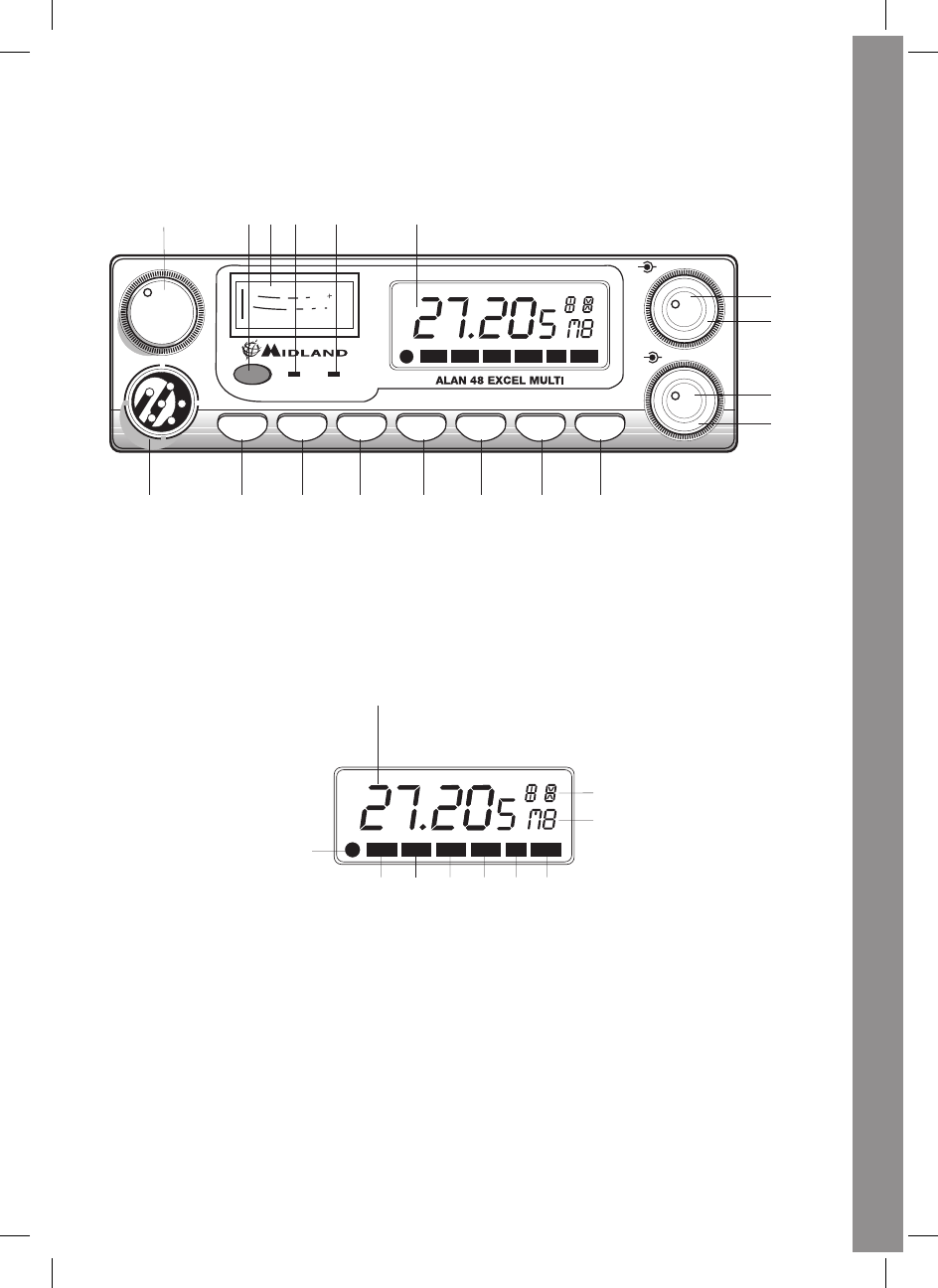
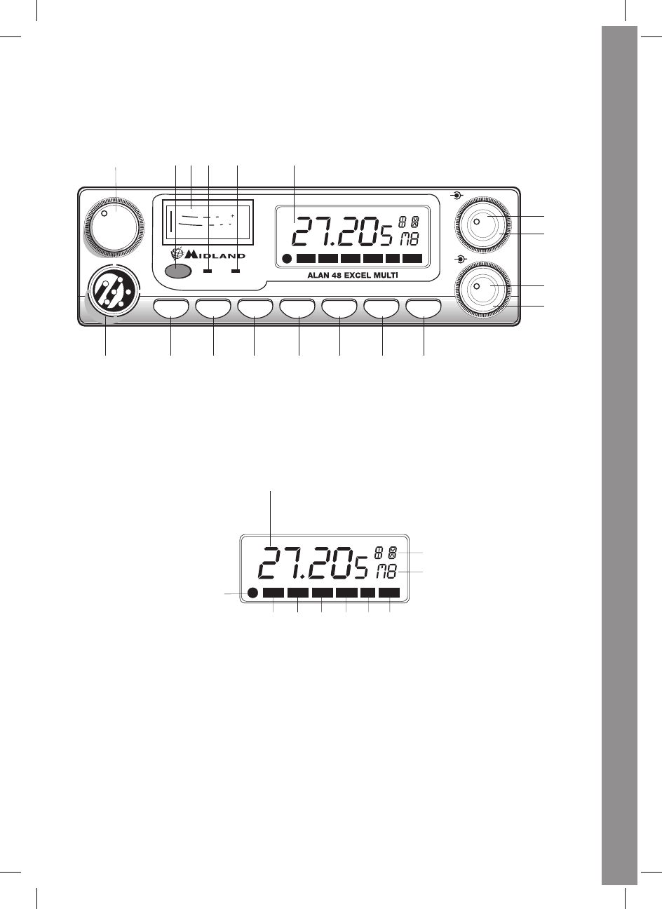
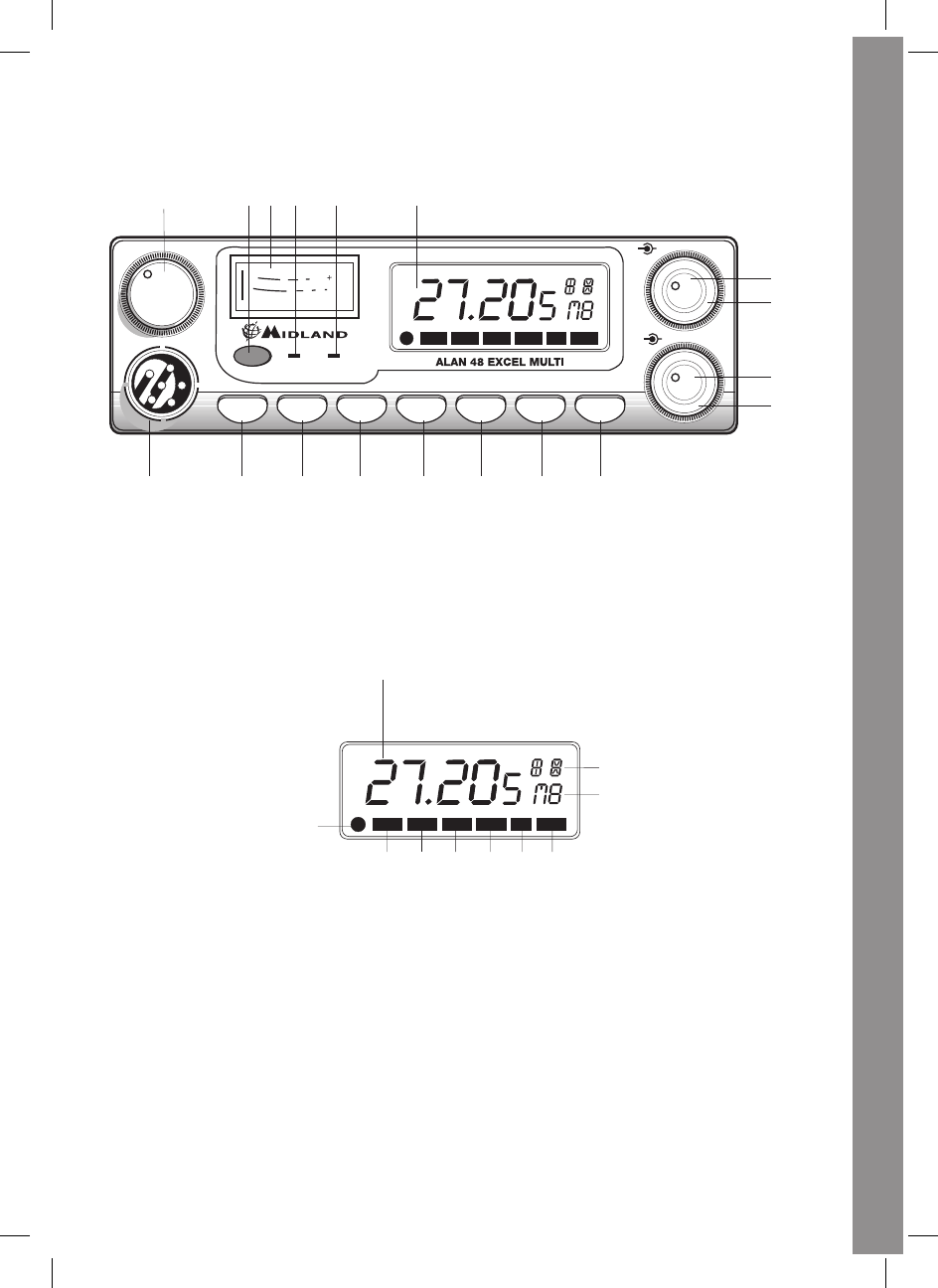
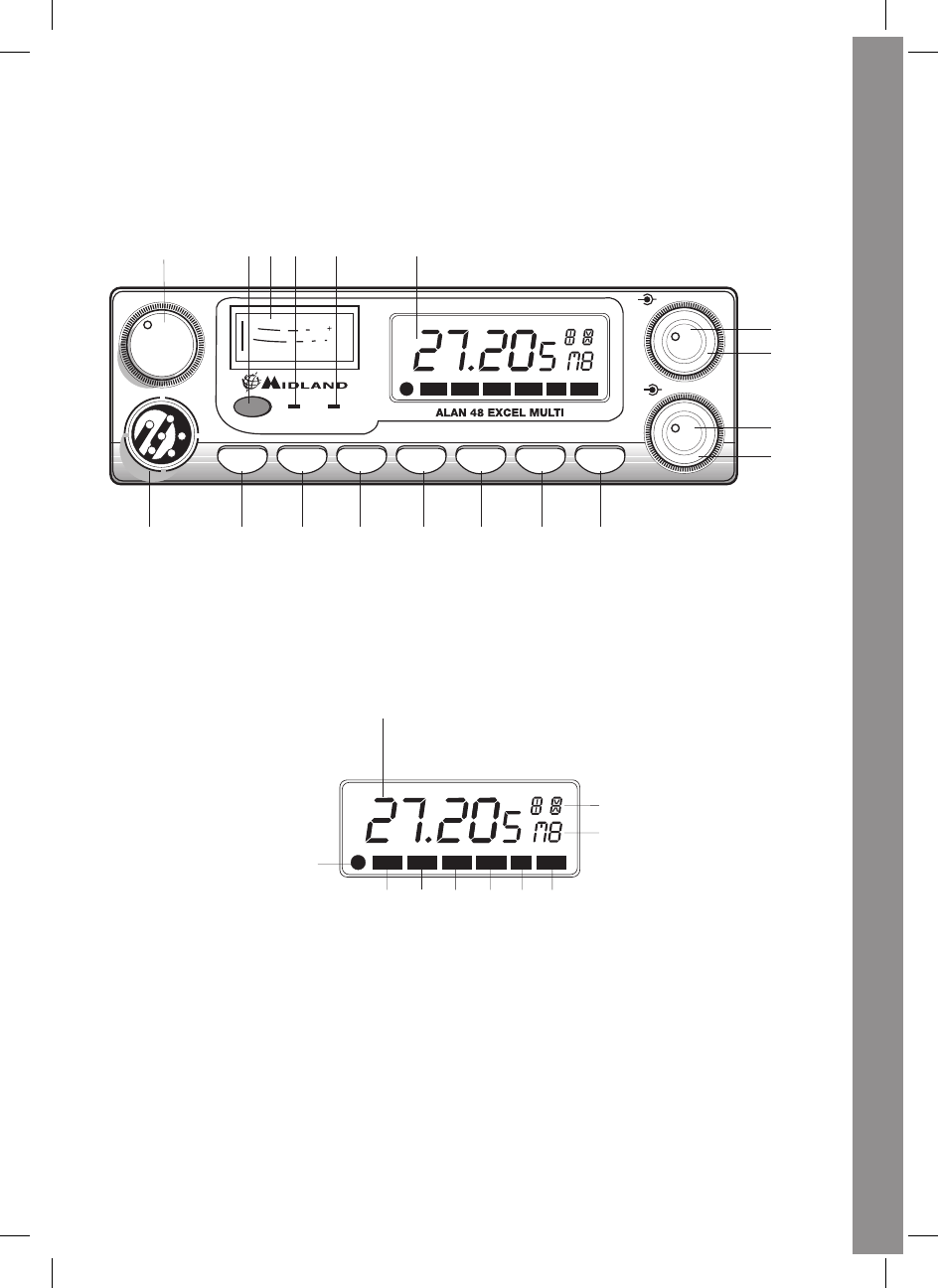
5. Indicador AM/FM: indica el modo operativo. FM: LED rojo; AM: LED verde.
6. Indicador RX/TX: indicador de recepción/transmisión. RX: LED verde; TX: LED
rojo.
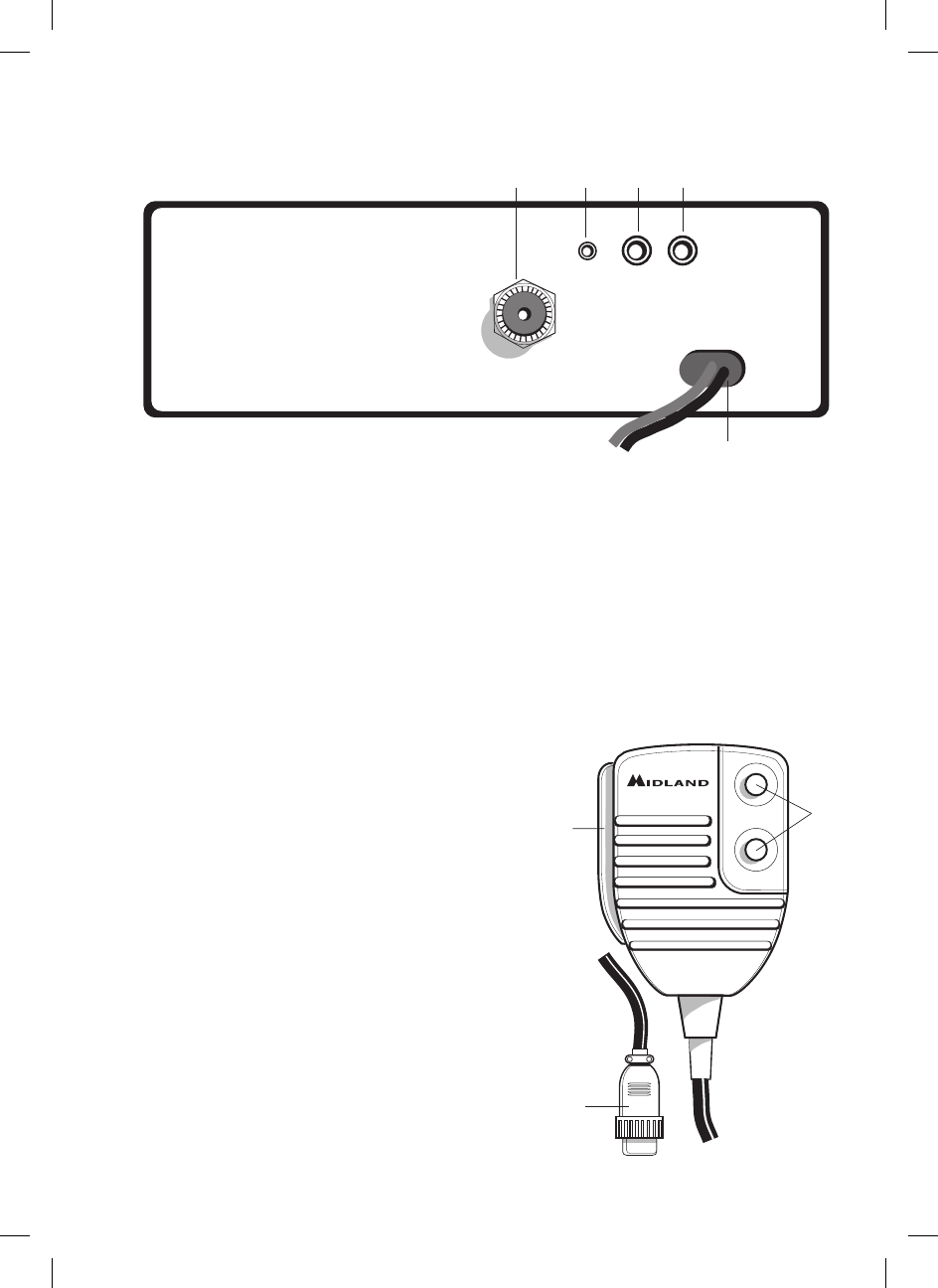
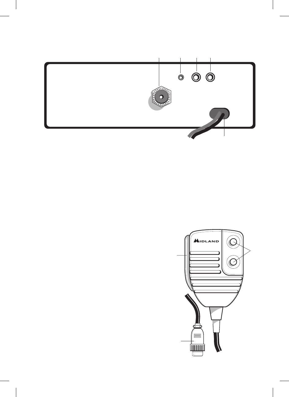
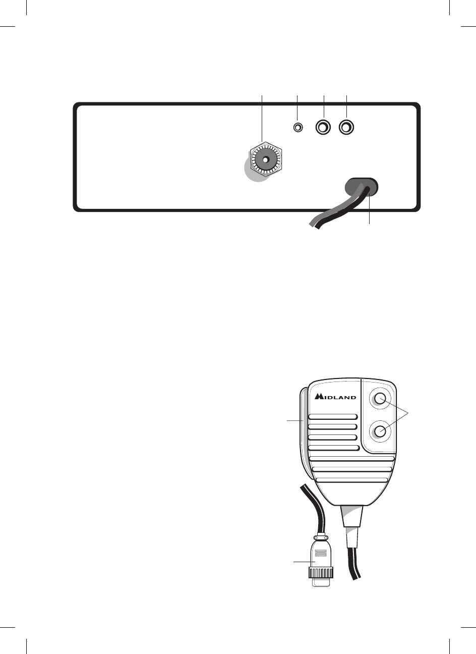
7. Selector CB-PA: situado en CB, el equipo actúa como transceptor. En posición
PA, si se conecta un altavoz a la toma posterior PA, el equipo se convierte en un
amplicador de BF, actuando el mando MIC como regulador de la amplicación.
8. Tecla FUNC: permite visualizar, a elección del usuario:
El canal o la frecuencia operativa pulsando FUNC durante 3 segundos.
Activar la segunda función de las teclas M (M1-M5).
M1 / M2 / M3 / M4 / M5: el equipo tiene la posibilidad de memorizar 5 canales
cualesquiera. Para memorizar uno, proceda como sigue:
Seleccione el canal que desea memorizar mediante el selector de canales o
mediante los pulsadores UP/DOWN del micrófono.
Pulse la tecla FUNC: en el display aparecerá “F”.
Mantenga pulsada durante 3 segundos la tecla M1/EMG (si desea grabar en la
memoria M1): El equipo emitirá un bip y en el display aparecerá “M1”.
Para memorizar otros canales en las restantes memorias, repita los puntos a, b y c,
cambiando en este último la memoria (M2-M5).
Para llamar un canal memorizado, pulse FUNC + la tecla correspondiente a la
memoria deseada (M1-M5).
Las teclas de memoria tienen una doble función, la segunda de las cuales, pasamos a
describir a continuación:
9. M1 - EMG: selecciona cíclicamente, además de grabar o llamar la memoria 1, el
canal 9, 19 y el canal en uso.
10. M2 - DW: permite la grabación o llamada de la memoria 2 y la activación de la función
DUAL WATCH Doble Escucha- que faculta al equipo a sintonizar simultáneamente
dos canales cualesquiera escogidos por el usuario.
Con esta función se monitorizará cíclicamente un segundo canal además del que
esté en uso. Ante la presencia de señal en el segundo canal, la comunicación en el
canal en uso se interrumpirá y el receptor conmutará automáticamente al segundo
canal. La monitorización se reiniciará transcurridos 5 segundos del cese de la señal
en el segundo canal.
Para activar esta función, siga las siguientes instrucciones:
Seleccione el canal principal o canal de uso mediante los selectores de cambio
de canal.
Pulse la tecla DW durante 3 segundos: el equipo emitirá un bip y en el display
parpadeará “DW.
Seleccione el segundo canal. Normalmente se escoge un canal en el que
puedan aparecer informaciones importantes, pero que no tenga un tráco
excesivo, ya que esto haría que el equipo estuviese conmutando continuamente
a este canal, con la incomodidad que esto acarrearía. Podríamos considerar el
canal de emergencia 9 u otro canal con las citadas características.
Pulse nuevamente la tecla DW durante 3 segundos: el equipo emitirá un bip y
el display mostrará “DWpermanentemente, visualizando alternativamente los
dos canales seleccionados.
11. M3 - SCAN: mediante esta tecla, además de grabar o llamar la memoria 3, se
activa la función SCAN Barrido- que hace que el equipo inicie una búsqueda
automática de canal ocupado. Para activar esta función:
Seleccione un canal libre y gire el control de squelch en sentido horario hasta
5
ESPAÑOL
que el ruido de fondo desaparezca.
Pulse SCAN: el display mostrará la palabra SCAN” y el equipo inicia la
búsqueda automática que durará hasta que encuentre una señal o se desactive
manualmente. Esta desactivación manual se puede efectuar de tres formas
diferentes: pulsando el PTT, girando el selector de canales o pulsando cualquier
tecla.
12. M4/LCR - AM/FM: además de permitir llamar o grabar la memoria 4, permite
seleccionar el modo operativo: AM (led 5 verde) o FM (led 5 rojo). Si además
selecciona una banda de frecuencia que opera en modo FM, la tecla AM/FM”
activa la función LCR (rellamada último canal utilizado)
13. M5 - LOCK: permite llamar o grabar la memoria 5. Además, sirve para bloquear
el teclado y el conmutador de canales, evitando así el cambio accidental de los
parámetros de uso del equipo. Permite no obstante, regular el volumen, squelch,
ganancia de micro y ganancia de RF.
14. N.K.: activa el supresor dinámico de ruidos ESP 2.
15. Mando MIC: controla la amplicación microfónica en transmisión. La posición
óptima de este control, se consigue experimentalmente hasta que se obtiene la
mejor modulación posible. Varíe el mando y solicite a otros usuarios que valoren su
modulación, actuando en consecuencia.
16. Mando RF: controla la sensibilidad en recepción, girando el mando en sentido
horario se aumenta la sensibilidad y viceversa. Tenga la precaución de disminuir
la sensibilidad cuando las señales recibidas sean muy fuertes ya que así mejorará
sensiblemente la calidad en recepción.
17. Mando VOL: enciende/apaga el equipo y regula el nivel de audio del altavoz
18. Mando SQ: permite regular el umbral de recepción. Para una máxima sensibilidad
del receptor, es preferible que se regule el mando al nivel en que el ruido de fondo
desaparece.
66
PANEL POSTERIOR
19. CONECTOR ANTENA: conector del tipo SO239.
20. TOMA S-METER: permite la conexión de un medidor de señal externo.
21. TOMA PA: conectando un altavoz de exteriores a este jack, puede usar la unidad
como amplicador de audio.
22. TOMA EXT: jack para la conexión de un altavoz externo (al conectarlo, el interno
queda desactivado).
23. POWER 13.2 VCC: toma de alimentación.
MICRÓFONO
1. PTT: botón de transmisión.
2. Botones UP/DOWN: Selector manual de
canales: UP: hacia arriba; DOWN: hacia
abajo.
3. Conector del micrófono de 6 pines.
UP
DOWN
2
1
3
19 20 21 22
23
ANTENNA
S-METER
PA EXT
7
ESPAÑOL
INSTALACIÓN
La seguridad y la facilidad son las consideraciones primordiales para efectuar el
montaje de cualquier equipo móvil. Todos los controles deben ser fáciles de alcanzar
por parte del operador, sin que ello interera en la correcta conducción del vehículo.
Seleccione la posición adecuada del vehículo donde instalar el transceptor y use el
soporte suministrado o eventualmente el soporte deslizante. Coloque los tornillos de
retención. El soporte de jación debe estar en contacto con las partes metálicas.
CONEXIÓN ELÉCTRICA
Asegúrese de que el transceptor está apagado. El equipo incluye un cable de
alimentación bicolor con un portafusibles insertado en el cable rojo (positivo). En la
alimentación de corriente continua es muy importante observar la polaridad, incluso
si la unidad está protegida contra la inversión accidental. Como norma, se identica el
polo positivo con el color rojo o con el signo “+”, y el polo negativo con el color negro
o con el signo “-“
Los mismos colores se encuentran presentes en la batería y en la caja de fusibles del
vehículo. Conecte correctamente el terminal del cable a la batería.
INSTALACIÓN DE LA ANTENA
1. Instale la antena lo más alta posible.
2. Cuanto más larga sea la antena, mejores prestaciones obtendrá.
3. Si es posible, monte la antena en el centro de la supercie escogida.
4. Mantenga el cable de antena a resguardo de fuentes de ruido eléctrico, tales como
del encendido del coche, etc.
5. Asegúrese de que dispone de una sólida conexión a masa metal a metal.
6. Impida que pueda dañarse el cable durante la instalación de la antena.
Advertencia: Para evitar provocar daños, nunca utilice su equipo sin asegurarse
de que está correctamente conectado a una antena adecuada. Se recomienda
un control periódico del cable y de la ROE.
88
FUNCIONAMIENTO DEL TRANSCEPTOR
1. Enchufe el micrófono en el jack correspondiente.
2. Asegúrese de que la antena está conectada al conector correspondiente.
3. Asegúrese de que el control del silenciador está girado completamente hacia la
izquierda.
4. Encienda la unidad y ajuste el control de volumen y squelch.
5. Seleccione el canal deseado.
6. Para transmitir, pulse el botón PTT y hable en un tono de voz normal.
7. Para recibir, libere el botón PTT.
SELECCIÓN BANDAS DE FRECUENCIA
La selección de las bandas de frecuencia debe efectuarse en función del país en el que
se va a utilizar el equipo.
Procedimiento:
1. Apague el equipo
2. Enciéndalo pulsando la tecla “N.K.”
3. Gire el mando “CHANNELy seleccione la banda de frecuencia deseada (“E” para
España – vea la tabla de bandas más abajo)
4. Pulse la tecla “LOCK” para nalizar la selección
NOTA: Si se selecciona una banda de frecuencia que sólo funciona en modo FM,
la tecla “AM/FM” activa la función LCR (rellamada último canal utilizado)
NOTA: en la banda de frecuencia UK se puede seleccionar directamente la banda
EC pulsando la tecla “LCR-A/F” durante aproximadamente 2 segundos
TABLA BANDAS DE FRECUENCIA
Siglas en el
display
País
I Italia 40 CH AM/FM 4W
I2 Italia 34 CH AM/FM 4W
D Alemania 80 CH FM 4W / 12 CH AM 1 W
D2 Alemania 40 CH FM 4W / 12 CH AM 1 W
D3 Alemania 80 CH FM 4W / 80 CH AM 1 W
EU Europa 40 CH FM 4W / 40 CH AM 1 W
EC CEPT 40 CH FM 4W
E España 40 CH AM/FM 4W
F Francia 40 CH FM 4W / 40 CH AM 1 W
PL Polonia 40 CH AM/FM 4W
UK
Inglaterra 40 CH FM 4W frecuencias inglesas + EC 40 CH FM
4W frecuencias CEPT
ATENCIÓN:
El estándar reconocido en todos los países europeos es 40CH FM 4W (EC) – Vea
tabla de “Restricciones al uso”
9
ESPAÑOL
ESPECIFICACIONES TÉCNICAS
Generales
Canales ..................................................................................40 FM (vea tabla bandas)
Rango de frecuencias ................................................................26.565 - 27.99125 MHz
Control de frecuencia ................................................................................................PLL
Gama de temperaturas de operación ....................................................-10 ºC a +55 ºC
Tensión de alimentación ................................................................... 13.8/24 Vcc ± 15%
Dimensiones .............................................150 (ancho) x 45 (alto) x 175 mm (profundo)
Peso .........................................................................................................................1 Kg
Receptor
Sistema de recepción .........................................Superheterodino de doble conversión
Frecuencia intermedia ........................................................................ 1ª FI: 10.695 MHz
................................................................................................................. 2ª FI: 455 KHz
Sensibilidad ...................................................... 0.5 µV para 20 dB SINAD en modo FM
..........................................................................0.5 µV para 20 dB SINAD en modo AM
Potencia de salida de audio a 10% THD ......................................... 2,0 W @ 8 Ohmios
Distorsión de audio ................................................................... Menos de 8% @ 1 KHz
Rechazo de imagen ...............................................................................................65 dB
Rechazo del canal adyacente ................................................................................65 dB
Relación señal/ruido ..............................................................................................45 dB
Consumo de corriente en espera .......................................................13,2 Vcc: 450 mA
.............................................................................................................24,0 Vcc: 520 mA
Transmisor
Potencia de salida .............................ciclo de trabajo del 10% 4 W AM/FM @ 13.2 Vcc
Modulación ................................................................................. AM: desde 85% a 95%
.................................................................................................... FM: 1.8 KHz ± 0.2 KHz
Respuesta de frecuencia ........................................................... Desde 400 Hz a 3 KHz
Impedancia de salida ....................................................RF 50 Ohmios no balanceados
Relación señal/ruido .................................................................................40 dB mínimo
Consumo ................................................ 13,2 Vcc: 1300 mA (potencia sin modulación)
................................................................ 24,0 Vcc: 1600 mA (potencia sin modulación)
Las especicaciones están sujetas a variaciones sin previo aviso.
© ALAN COMMUNICATIONS, SA: 2004
1
FRANÇAIS
SOMMAIRE
Introduction ........................................................................................... 2
Description des commandes ................................................................ 3
Installation ............................................................................................ 7
Branchement électrique ..................................................................... 7
Installation de l’antenne ..................................................................... 7
Comment utiliser l’ALAN 48 EXCEL MULTI .........................................8
Sélection des bandes de fréquence .................................................. 8
Tableau des bandes de fréquence..................................................... 8
Caractéristiques techniques ................................................................. 9
Renseignement important
Mise à jour sur les restrictions nationales
Pour utiliser cette radio en Belgique, en Angleterre, en Espagne et en
Suisse, les résidents doivent être titulaires d’une licence individuelle;
ceux qui viennent de l’étranger jouissent d’un libre usage en FM, tandis
que pour l’AM ils doivent avoir la licence du pays d’origine.
Pour les étrangers qui arrivent en Italie, il est nécessaire d’acquérir une
autorisation italienne.
L’Autriche au contraire n’autorise pas l’usage des émetteur-récepteurs
CB multi-standard (programmables). Nous vous conseillons de respecter
scrupuleusement cette directive et de ne pas utiliser cette radio dans le
territoire autrichien.
En Allemagne, sur certaines zones frontalières, l’émission comme
station base sur les canaux 41-80 n’est pas permise.
Vous pouvez obtenir des renseignements additionnels auprès du RegTP
local.
Les mises à jour des restrictions à l’usage en Allemagne sont publiés
sur le website ALAN-Albrecht www.alan-albrecht.info.
22
ALAN 48 EXCEL MULTI est un émetteur-récepteur dont la caractéristique
principale est la possibilité de sélectionner n’importe quelle bande CB
européenne avec une procédure simple et immédiate. ALAN 48 EXCEL
MULTI est doué du dispositif “ESP2” (suppresseur dynamique des
parasites) qui réduit les bruits indésirables sur l’audio jusqu’à 95% en
facilitant l’écoute des signaux purs et en atténuant les signaux gênants.
De cette façon, l’écoute sera plus compréhensible et agréable.
Le large afcheur multi-fonction permet la visualisation du nombre du
canal en usage ou de la fréquence correspondante. Il est aussi retro-
éclairé en facilitant l’usage nocturne. ALAN 48 EXCEL MULTI est doué
d’un S-Metre analogique indiquant la puissance d’émission, le signal
reçu et - nouveauté absolue – il a aussi un réducteur interne de tension
pour un usage avec double alimentation, 13.2V et 24V.
Lunité est pre-réglée en usine sur la bande “EC“ CEPT 40CH FM
4W.
3
FRANÇAIS
DESCRIPTION DES COMMANDES
PANNEAU FRONTAL
1. Sélecteur canaux: il permet la sélection manuelle des canaux.
2. Prise microphone: insérer la che microphone dans cette prise.
3. Indicateur: cet instrument indique l’intensité des signaux en réception et la
puissance de sortie RF de lémetteur.
4. Lafcheur illuminé multi fonctions
a) Nombre canaux sélectionnés (de 1 à 40) ou fréquence correspondante
b) Activation bouton FUNC
c) ESP : activation suppression dynamique des bruits de fond
d) DW : fonction DUAL WATCH activée
e) EMG : indicateur fonction bloc boîtier et sélecteur activé
f) LOCK : indicateur fonction LOCK activé
g) SCAN : indicateur fonction SCAN activé
h) M1-M2-M3-M4-M5: indicateurs mémoire canaux.
i) Indique la bande de fréquence sélectionnée.
j) Il est visualiquand la radio transmet en basse puissance (condition qui se
vérie seulement pour certaines bandes de fréquence voir le tableau des
bandes)
N.K.M5
LOCK
M4/LCR
AM/FM
M3
SCAN
M2
DW
M1
EMG
FUNC
01
3
5
7
9
30
2
3
5
10
0
POWER
MIC
CH
VOL
SQ
MIC
RF
TX RX AM FM
CB/PA
1
2
3 4567
8 9 10 11 12 13 14
16
18
15
17
F
EMG DWESP LOCK SCANLOW
a
b
ecfdg
i
j
h
F
EMGDWESP LOCK SCANLOW
44
5. Indicateur « AM/FM» : indique le mode opératif. FM LED: rouge –
AM : LED verte.
6. Indicateur « RX/TX »: indicateur de réception/transmission.
Position RX : LED verte – position TX : LED rouge.
7. Sélecteur « CB-PA»
Position CB: dans cette position, l’appareil est activé comme émetteur- récepteur.
Position PA : ce mode de fonctionnement est possible seulement si on branche un
haut-parleur à la prise PA à l’arrière (écrit « PA » visualisée sur le l’afcheur). Dans
ce cas, la commande « MIC » est utilisée comme contrôle de l’amplicateur.
8. Bouton FUNC: ce bouton permet, au choix, de :
Visualiser le canal ou la fréquence opérative en appuyant sur « FUNC » pendant
3 secondes environ;
Activer la seconde fonction des boutons «M » (M1/M5).
M1/M2/M3/M4/M5
La radio a la possibilité de moriser et de rappeler 5 canaux au choix précédemment
mémorisés. Pour mémoriser, procéder comme suit :
A. Sélectionner le canal que l’on désire mémoriser avec le sélecteur canal ou le
bouton « UP/DOWN » sur le microphone ;
B. Appuyer sur le bouton « FUNC » : l’afcheur montrera un « F »;
C. Tenir appuyer pendant 3 secondes environ le bouton «M1/EMG » : la radio
émettra un «bip » et l’afcheur montrera l’écriture «M1 ».
9. Bouton « M1 – EMG»
Il permet de mémoriser la mémoire n° 1 et de rappeler le canal d’urgence
La pression du bouton « M1/EMG » sélection les canaux 9, 19 et le canal en
usage.
10. Bouton « M2 – DW»
Permet la mémorisation de la mémoire numéro 2 et l’activation de la fonction DUAL
WATCH, qui consiste à rester syntoniser en même temps sur deux canaux au
choix.
Avec cette fonction, on veille un second canal. En présence d’un signal sur le second
canal, la conversation sur le canal pré choisi s’interrompt et le récepteur commutera
automatiquement sur le second canal. Il reviendra ensuite sur le premier canal à la
n du signal.
Pour activer cette fonction, opérer comme suit :
Sélectionner le canal désiré avec le sélecteur canaux ou le bouton « UP/DOWN »
et sur l’afcheur l’écriture « DW» clignote
Sélectionner le second canal désiré avec le sélecteur canaux ou le bouton « UP/
DOWN » sur le microphone
Appuyer le bouton « DW » pendant 3 secondes environ : la radio émettra un BIP,
l’afcheur montrera l’écriture « DW » permanente et visualisera alternativement les
deux canaux sélectionnés.
11. Bouton « M3 – SCAN»: avec ce bouton, on mémorise la mémoire n° 3 et on active
la fonction « SCAN » (recherche automatique d’un canal occupé).
Pour activer cette fonction, opérer comme suit :
- sélectionner un canal libre et tourner le bouton du squelch dans le sens des
aiguilles d’une montre de façon que les bruits de fond disparaissent;
- appuyer sur le bouton « M3/SCAN » : lafcheur montrera l’écriture « SCAN
» et l’émetteur récepteur effacera automatiquement et répétitivement tous les
canaux jusqu’à ce qu’il trouve le canal en service.
5
FRANÇAIS
La fonction « SCAN » peut être annulée de trois façons :
- en appuyant sur le bouton PTT
- en tournant le sélecteur canaux
- en appuyant sur n’importe quel bouton.
12. Touche “M4/LCR - AM/FM”
Cette touche permet la mémorisation de la mémoire n° 4 et la sélection du mode
opératif (AM/FM).
Mode AM : voyant 5 de couleur verte ; mode FM : voyant 5 de couleur rouge. Si
vous sélectionnez une bande de fréquence opérant seulement en modulation FM,
la touche “AM/FM” active la fonction LCR (rappel du dernier canal utilisé).
13. Touche “M5 - LOCK
Il permet de mémoriser la mémoire n° 5 et dactiver la fonction “LOCK” (bloc
clavier, lecteur de canaux et touche UP/DOWN du microphone pour éviter
d’accidentelles pressions des touches).
14. Touche “N.K.”
Touche d’activation de la suppression dynamique des bruits de fond (voir
introduction).
15. Bouton “MIC”
Contrôle de l’amplication microphonique en émission.
La meilleure position pour cette touche est recherchée expérimentalement de façon
à obtenir la meilleure modulation possible.
16. Bouton “RF”
Contrôle de la sensibilité en ception. En tournant le bouton dans le sens des
aiguilles d’une montre, on augmente la sensibilité, dans le sens contraire, on la
diminue.
17. Bouton « VOL »
Ce bouton permet l’allumage de l’appareil et le réglage du volume au niveau
désiré.
18. Bouton “SQ”
Il permet le réglage du niveau de seuil de réception. Pour une plus grande sensibili
du récepteur, il est préférable que la commande soit réglée au niveau précis ou les
bruits de fond du récepteur sont éliminés.
66
PANNEAU POSTERIEUR
19. Connecteur antenne: il est prévu le connecteur SO 239
20. Prise S. METER: elle permet le branchement d’un instrument externe.
21. Prise PA: Avec un branchement à un haut-parleur externe, elle permet d’utiliser
l’appareil comme amplicateur audio.
22. Prise EXT: prise haut-parleur externe (ce branchement exclut l’usage du haut-
parleur interne).
23. POWER 13,2 Volts: prise d’alimentation.
MICROPHONE
1. Touche d’émission.
2. Bouton UP/DOWN: lection canaux vers
le haut (UP) et vers le bas (DOWN).
3. Connecteur microphone 6 pins.
UP
DOWN
2
1
3
19 20 21 22
23
ANTENNA
S-METER
PA EXT
7
FRANÇAIS
INSTALLATION
Rechercher et localiser, sur le véhicule, la position pour installer l’appareil, en utilisant
l’étrier de support fourni. Ce positionnement doit être fait de fon à ne pas gêner le
conducteur, mais doit aussi être facilement accessible. Percer un trou (diamètre 3 mm
environ) dans la carrosserie pour le xage avec les vis. Positionner l’appareil sur l’étrier
de xation. Contrôler que les vis soient bien serrées, en tenant compte des vibrations
créées par les véhicules.
BRANCHEMENT ELECTRIQUE
Avant de procéder à cette opération, contrôler que l’émetteur récepteur soit éteint
(bouton du volume complètement tourné à gauche, après le déclic. Lappareil est doté
d’un petit câble d’alimentation bicolore avec un porte fusible inséré sur câble rouge
(positif). Pour le branchement, il est ts important de respecter la polarité, même si
l’appareil est protégé contre l’inversion accidentelle. De norme, on indique le pôle positif
en rouge ou avec le signe “+” et le pôle négatif en noir ou avec le signe”-”. Les mêmes
signes ou couleurs indicatifs sont retrouvés sur les batteries (accumulateur ou autres)
et dans la boîte de fusibles des automobiles.
ATTENTION
Pour obtenir de meilleures performances, il est recommandé d’installer la radio
où l’air est bien recyclé.
INSTALLATION DE LANTENNE
Informations utiles
1. Installer l’antenne dans la partie la plus haute du véhicule
2. Plus grande est la longueur de l’antenne, meilleur est son rendement.
3. Si possible, installer l’antenne au centre de la supercie métallique choisie.
4. Tenir le câble de l’antenne loin des sources de dérangements électriques.
5. S’assurer davoir une bonne masse.
6. Eviter des dommages aux câbles.
Attention : ne jamais utiliser la radio CB sans avoir installé une antenne
appropriée pour ne pas courir le risque d’endommager l’émetteur, pour la même
raison, contrôler périodiquement le TOS.
88
UTILISATION DE LALAN 48 EXCEL MULTI
Après avoir installer votre CB et votre antenne, suivre attentivement les instructions ci-
après pour le bon fonctionnement de votre appareil.
1. Visser la che dans la prise du microphone sur le panneau.
2. S’assurer que l’antenne soit branchée au connecteur.
3. S’assurer que la commande du squelch soit complètement tournée vers la gauche.
4. Allumer lappareil et régler le volume pour un bon niveau sonore.
5. lectionner le canal désiré avec le sélecteur canal ou le bouton UP/DOWNdu
microphone.
6. Pour émettre, appuyer sur la touche de transmission PTT sur le microphone.
7. Pour recevoir, le relâcher.
SELECTION DES BANDES DE FREQUENCE
Les bandes de fréquence doivent être choisies selon le pays ou vous voulez opérer.
1. Eteignez l’appareil.
2. Allumez la radio et appuyez en même temps la touche “N.K.”.
2. Avec la commande “CHANNEL, sélectionnez la bande de fréquence désirée (voir
le tableau ci-dessous).
3. Appuyez sur la touche « LOCK » pour terminer la sélection.
NOTE: Quand vous sélectionnez une bande de fréquence seulement en mode
FM, la touche “AM/FM” active la fonction LCR (rappel du dernier canal utilisé).
NOTE: dans la bande de fréquence UK, il est possible de lectionner directement
la bande EC en pressant le bouton “LCR-A/F” durant 2 secondes.
TABLEAU DES BANDES DE FREQUENCES
Sigle sur le
display
Pays
I Italie 40 CH AM/FM 4Watt
I2 Italie 34 CH AM/FM 4Watt
D Allemagne 80 CH FM 4Watt / 12 CH AM 1 Watt
D2 Allemagne 40 CH FM 4Watt / 12 CH AM 1 Watt
D3 Allemagne 80 CH FM 4Watt / 80 CH AM 1 Watt
EU Europe 40 CH FM 4Watt / 40 CH AM 1 Watt
EC CEPT 40 CH FM 4Watt
E Espagne 40 CH AM/FM 4Watt
F France 40 CH FM 4Watt / 40 CH AM 1 Watt
PL Pologne 40 CH AM/FM 4Watt
UK Angleterre 40 CH FM 4Watt fréquences anglais + EC 40 CH FM
4Watt fréquences CEPT
ATTENTION!
La bande de fréquence reconnue sûrement dans tous les pays européens est
40CH FM 4W (EC) - voir le tableau pour les restrictions à l’usage.
9
FRANÇAIS
CARACTERISTIQUES TECHNIQUES
GENERALES
Nombre de canaux .............................................................40 FM (voir tableau bandes)
Gamme de fréquence ................................................................26.565 - 27.99125 MHz
Contrôle de fréquence ..........................................................................................à PLL
Température ............................................................................................... - 10°/+55° C
Tension d’alimentation ....................................................................... 13.2/24 Vcc ±15%
Dimension .......................................................................150 (L) x 45 (H) x 175 (P) mm
Poids ....................................................................................................................... 1 kg
RECEPTEUR
Système réception ............................................. superhétérodyne à double conversion
Fréquences intermédiaires .............................................................. I IF : 10.695 MHz
..............................................................................................................II IF : 455 KHz
Sensibilité ...................................................................0.5 µV pour 20 DB SINAD en FM
....................................................................................0.5 µV pour 20 DB SINAD en AM
Puissance de sortie audio @ 10 % THD ............................................... 2.0 W @ 1 KHz
Distorsion audio .........................................................................moins de 8 % @ 1 KHz
Réjection d’image ..................................................................................................65 DB
Sélectivité sur canaux ...........................................................................................65 DB
Rapport signal bruit ..............................................................................................45 DB
Consommation en veille ........................................................................... 13.2V: 450mA
.................................................................................................................... 24V: 520 mA
EMETTEUR
Puissance de sortie .............................................cycles à 10% 4 W AM/FM @ 13.2Vcc
Modulation ..................................................................................... AM : de 85 % à 95 %
.................................................................................................FM : 1,8 KHz +/- 0,2 KHz
Réponse en fréquence ...........................................................................400 Hz ÷ 3 KHz
Impédance de sortie .......................................................................RF 50 Ohm balancé
Rapport signal bruit ....................................................................................... 40 DB MIN
Courant absorbé .....................................13.2V: 1300mA (puissance sans modulation)
....................................................................24V: 1600mA (puissance sans modulation)
Les spécications peuvent varier sans préavis.
1
PORTUGUES
ÍNDICE
Introdução.............................................................................................2
Descrição dos comandos ..................................................................... 3
Instalação .............................................................................................7
Conexão elétrica ................................................................................ 7
Instalação da antena ......................................................................... 7
Uso do ALAN 48 EXCEL MULTI ...........................................................8
Selecção das bandas de frequência.................................................. 8
Tabela das bandas de frequência ...................................................... 8
Características técnicas ....................................................................... 9
Nota importante
Actualização sobre restrições nacionais:
Para poder utilizar o aparelho na Bélgica, Grã-Bretanha, Espanha e
Suíça os usuários residentes devem munir-se de uma licença individual;
os que provêm do exterior gozam do livre uso em FM, enquanto em AM
devem possuir uma licença do país de origem.
Para os estrangeiros que chegam à Itália, é necessária uma autorização
Italiana.
A Áustria não autoriza o uso de radiotelefones CB multi-standard
(programáveis). Aconselha-se respeitar escrupolosamente esta directiva
e não utilizar o aparelho em território austríaco.
Ao longo das fronteiras de algumas áreas da Alermanha, a transmissão
do canal 41 ao 80 não é permitida. Dirija-se ao escritório de noticações
para detalhes ulteriores.
Actualizações sobre restrições ao uso em vigor na Alemanna são
constantemente publicadas no website ALAN-Albrecht www.alan-
albrecht.info.
22
ALAN 48 EXCEL MULTI é um radiotelefone veicular cuja característica
principal consiste na possibilidade de seleccionar qualquer banda CB
européia de modo simples e rápido. ALAN 48 EXCEL MULTI é dotado
do dispositivo ESP2” (supressor dinâmico de distúrbios) que permite
reduzir consideravelmente os distúrbios sonoros (até 95%) facilitando a
escuta mesmo com sinal disturbado.
O amplo display multifuncional consente visualizar o número do canal
em uso ou da frequência correspondente, além de possuir iluminação
traseira para a visualização noturna. ALAN 48 EXCEL MULTI também é
dotado de um instrumento S-Meter analógico que consente uma cômoda
visualização da potência transmitida e do sinal recebido e -novidade
absoluta - dispõe de um redutor interno de tensão, que permite o seu
uso com dupla corrente, 13.2V e 24V.
O aparelho é fornecido com a banda “EC” CEPT 40CH FM 4W.
3
PORTUGUES
DESCRIÇÃO DOS COMANDOS
1. Selector de canais: permite seleccionar manualmente os canais.
2. Tomada para o microfone: inserir o pino do microfone nesta tomada.
3. Indicador: este instrumento indica a intensidade dos sinais em recepção e a
potência de saída RF do transmissor.
4. Display multifunção com iluminação traseira
a. mero de canais seleccionados (de 1 a 40) ou frequência correspondente.
b. Activação da tecla FUNC.
c. ESP: activação do supressor dinâmico de distúrbios.
d. DW: função DUAL WATCH activada
e. EMG: indicador de activação do canal 9 / 19 ou canal em uso
f. LOCK: indicador da função de bloqueio das teclas e selectores activada
g. SCAN: indicador da função SCAN activada
h. M1-M2-M3-M4-M5: indicadores das memórias dos canais .
i. Indica a banda de frequência seleccionada.
j. Vê-se quando o rádio transmite em baixa potência (condição que se verica
somente em algumas bandas de frequência - veja a tabela de bandas)
N.K.M5
LOCK
M4/LCR
AM/FM
M3
SCAN
M2
DW
M1
EMG
FUNC
01
3
5
7
9
30
2
3
5
10
0
POWER
MIC
CH
VOL
SQ
MIC
RF
TX RX AM FM
CB/PA
1
2
3 4567
8 9 10 11 12 13 14
16
18
15
17
F
EMG DWESP LOCK SCANLOW
a
b
ecfdg
i
j
h
F
EMGDWESP LOCK SCANLOW
44
5. Indicador “AM/FM”
Indica o modo operativo. FM: LED vermelha; AM: LED verde.
6. Indicador “RX/TX”
Indicador de recepção / transmissão. Posição RX: LED verde; posição TX: LED
vermelha.
7. Selector “CB - PA
Posição “CB” : nesta posição, o aparelho opera como radiotelefone.
Posição “PAeste modo de funcionamento é possível somente se for conectado
um altifalante à tomada PA na parte posterior (escrita “PA” visualizada no display).
Neste caso, o comando “MIC” é usado como controlo da amplicação.
8. Tecla FUNC
Esta tecla permite, conforme a escolha do utilizador:
Visualizar o canal ou a frequência operativa premindo “FUNC” durante cerca de
3 segundos.
Activar as segundas funções das teclas “M” (M1/M5).
M1 / M2 / M3 / M4 / M5:
O rádio pode memorizar e chamar, quando necessário, 5 canais a escolha,
previamente memorizados. Para memorizar um canal, proceda da seguinte
maneira:
A) Seleccione o canal que deseja memorizar com o selector de canais ou com as
teclas “UP/DN” do microfone;
B) Prima a tecla “FUNC”: o display mostrará um ”F”
C) Mantenha premida por cerca de três segundos a tecla “M1/EMG”: o rádio
emitirá um “BIP” e o display mostrará a escrita “M1”.
Para memorizar outros canais repita os pontos A e B e seleccione uma memória
diversa.
Para chamar um canal precedentemente memorizado prima a tecla FUNC” e em
seguida a tecla da memória desejada.
As teclas de memorização de canais têm uma dupla função; abaixo se encontram
descritos os dois modos de funcionamento.
9. Botão “M1 - EMG”
Permite memorizar a memória número 1 e chamar os canais de emergência.
A pressão da tecla M1/EMGselecciona ciclicamente o canal 9, 19 e o canal em
uso.
10. Botão “M2 - DW
Permite a memorização da memória número 2 e a activação da função DUAL
WATCH, que consiste em permanecer sintonizado ao mesmo tempo em dois canais
a escolha do utilizador.
Com esta função é possível monitorar ciclicamente um segundo canal. Na presença
de um sinal no segundo canal, a conversação no primeiro canal será interrompida
e o receptor comutará automáticamente para o segundo canal. A monitoragem
recomeçará 5 segundos depos que cessar o sinal.
Para activar esta função, proceda da seguinte maneira:
- Seleccione o canal desejado com o selector de canais ou com as teclas UP/
DN” do microfone;
- Prima a tecla DWpor cerca de 3 segundos: o rádio emitirá um BIP e no display
piscará a escrita “DW.
- Seleccione o segundo canal desejado com o selector de canais ou com as
teclas “UP/DN” do microfone;
5
PORTUGUES
- Prima novamente a tecla DWpor cerca de 3 segundos: o rádio emitirá um
BIP, o display mostrará a escrita “DW” permanente e alternará a visualização
dos dois canais seleccionados.
11. Botão “M3 - SCAN”
Com este botão se memoriza a memória número 3 e se activa a função “SCAN
(busca automática de um canal ocupado).
Para activar questa função, proceda da seguinte maneira:
- seleccione um canal livre e gire o botão do squelch no sentido horário até que
desapareça o ruído de fundo;
- prima a tecla M3/SCAN”: o display mostrará a escrita “SCAN” e o radiotelefone
fará o scanning automático e repetido de todos os canais até encontrar um
canal em uso.
A função “SCAN” pode ser anulada em três modos: premindo a tecla PTT, girando
o selector de canais ou premindo qualquer tecla.
12. Botão “M4/LCR - AM/FM
Esta tecla consente a memorização da memória número 4 e a seleão do modo
operativo (AM/FM). Modo AM: luz 5 de cor verde; Modo FM: luz 5 de cor vermelha.
Se além disso for seleccionada uma banda de frequência que opera somente em
FM, a tecla ”AM/FM” activará a função LCR (chamada do último canal utilizado).
13. Botão “M5 - LOCK
Permite memorizar a memória número 5 e activar a função LOCK (bloqueio do
teclado, selector de canais e teclas UP/DOWN do microfone, para evitar que as
teclas sejam premidas acidentalmente).
14. Tecla “N.K.”
Tecla de activação do supressor dinâmico de distúrbios (Ver introdução).
15. Boo “MIC”
Controlo da amplicação microfónica em transmissão.
A melhor posição para este botão deve ser procurada experimentalmente, a m de
obter a melhor modulação possível.
16. Botão ”RF
Controlo da sensibilidade em recepção. Girando o botão no sentido horário, aumenta
a sensibilidade; girando-a no sentido anti-horário, diminui a sensibilidade.
17. Botão “VOL
Este botão permite ligar o aparelho e regular o volume no nível desejado.
18. Botão “SQ”
Permite a regulagem do nível de recepção. Para obter a xima sensibilidade do
receptor, é preferível que o comando seja regulado somente no nível exacto em que
o ruído de fundo do receptor é eliminado.
66
PAINEL POSTERIOR
19. Conector da antena: é fornecido o conector SO 239.
20. Tomada S.METER: permite conectar um instrumento externo.
21. Tomada PA: conectada a um altifalante externo, permite utilizar o aparelho como
amplicador áudio.
22. Tomada EXT: tomada do altifalante externo (esta conexão exclude o uso do
altifalante interno).
23. POWER 13.2 Vcc: tomada de corrente.
MICROFONE
1. Botão de transmissão.
2. Botões UP/DOWN: selecção de canais
para cima (up) e para baixo (DN).
3. Conector microfónico 6 pin.
UP
DOWN
2
1
3
19 20 21 22
23
ANTENNA
S-METER
PA EXT
7
PORTUGUES
INSTALAÇÃO
Procurar e localizar, no veículo, a posição para instalar o aparelho, utilizando a presilha
de suporte fornecida. O posicionamento deve ser feito de modo a não criar obstáculos
a quem dirige, mas ao mesmo tempo deve ser facil-mente acessível. Fazer os furos
(diâmetro de cerca de 3 mm.) na carroceria para xar com os parafusos. Posicionar o
aparelho na presilha de xagem. Certcar-se que os parafusos estejam bem apertados,
considerando as vibrações criadas pelo veículo.
CONEXÃO ELÉTRICA
Antes de iniciar esta operação, certicar-se que o radiotelefone esteja desligado (botão
do volume completamente girado para a esquerda, depois do estalo).
O aparelho é dotado de um o de corrente bicolor com um porta-fusível inserido no
o vermelho (positivo). Na conexão é muito importante respeitar a polaridade, mesmo
sendo o aparelho protegido contra inversões acidentais. Identica-se o pólo positivo
com a cor vermelha ou com o sinal ‘’+’’, e o pólo negativo com a cor preta ou com o
sinal “-”.
Os mesmos sinais (ou cores) de identicação são encontraddos na bateria (acumulador
ou outro) e na caixa dos fusíveis do automóvel. Recomenda-se conectar de modo
correcto e estável os terminais do o à bateria.
ATENÇÃO
Para obter a melhor performance, recomendamos a instalação do equipamento
num lugar com suciente ventilação.
Nota: Na banda de frequências di Reúno Unido (UK), pode seleccionar
directamente a banda EC carregado na tecla “LCR-A/F” durante mais de 2
segundos.
INSTALAÇÃO DA ANTENA
Informações úteis :
1) Instale a antena na parte mais alta do veículo.
2) Quanto mais longa for a antena, melhor será o seu rendimento.
3) Se possível, instale a antena no centro da superfície metálica escolhida.
4) Mantenha o o da antena longe de fontes de distúrbios eléctricos.
5) Certique-se que dispõe de uma boa massa.
6) Evite danos aos os.
Atenção: nunca use o rádio CB sem ter instalado uma antena apropriada,
para não correr risco de danos ao transmissor; pelo mesmo motivo verique
periodicamente o ROS.
88
USO DO ALAN 48 EXCEL MULTI
Após ter instalado o seu CB e a sua antena, siga atentamente as istruções abaixo para
obter o melhor funcionamento do seu aparelho.
1) Atarraxe o pino na tomada do microfone, no painel.
2) Certique-se que a antena esteja conectada.
3) Certique-se que o comando de squelch esteja completamente girado à esquerda.
4) Ligue o aparelho e regule o comando do volume no nível sonoro adequado.
5) Seleccione o canal desejado com o selector de canais ou com as teclas UP /
DOWN” do microfone.
6) Para transmitir, prima o botão de transmissão PTT do microfone.
7) Para receber, solte-o.
SELECÇÃO DE BANDAS DI FREQUÊNCIA
A escolha das bandas de frequência deve ser feita seguno o país em que se pretende
operar.
Procedimento:
1. Desligue o rádio.
2. Ligue o aparelho premindo a tecla “N.K.”.
3. Gire o botão “CHANNELe seleccione a banda de frequência desejada (ver tabela
de bandas).
4. Prima a tecla “LOCK” para terminar a seleão.
NOTA: Seleccionando uma banda de frequência que opera somente em FM, a
tecla “AM/FM” activará a função LCR (chamada do último canal selecionado).
TABELA DE BANDAS DE FREQUÊNCIA
Sigla no display País
I Itália 40 CH AM/FM 4Watt
I2 Itália 34 CH AM/FM 4Watt
D Alemanha 80 CH FM 4Watt / 12 CH AM 1 Watt
D2 Alemanha 40 CH FM 4Watt / 12 CH AM 1 Watt
D3 Alemanha 80 CH FM 4Watt / 40 CH AM 1 Watt
EU Europa 40 CH FM 4Watt / 40 CH AM 1 Watt
EC CEPT 40 CH FM 4Watt
E Espanha 40 CH AM/FM 4Watt
F França 40 CH FM 4Watt / 40 CH AM 1 Watt
PL Polónia 40 CH AM/FM 4Watt
UK Inglaterra 40 CH FM 4Watt frequências inglesas + + EC 40 CH
FM 4Watt frequências CEPT
ATENÇÃO:
O standard seguramente reconhecido em todos os países europeus é 40CH FM
4W (EC) - Ver tabela “Restrições de uso” -
9
PORTUGUES
CARACTERÍSTICAS TÉCNICAS
Gerais
Canais ..............................................................................40 FM (ver tabela de bandas)
Gama de frequência ...................................................................26.565 - 27.99125 MHz
Controlo de frequência ..........................................................................................a PLL
Temperatura ................................................................................................ -10° / +55°C
Tensão de corrente ........................................................................... 13.2/24 Vcc ±15%
Medidas ................................................................................150(L) x 45(A) x 175(P)mm
Peso ........................................................................................................................1 Kg.
Receptor
Sistema receptor ....................................................Supereterodina de dupla conversão
Frequência intermediária ..................................................................... I° IF:10.695 MHz
...................................................................................................................II° IF:455 KHz
Sensibilidade ................................................................. 0.5µV por 20dB SINAD em FM
.......................................................................................0.5µV por 20dB SINAD em AM
Potência de saída áudio @10% THD.................................................... 2.0 W @ 8 Ohm
Distorção áudio ...........................................................................Menos de 8% @ 1KHz
Rejeição a imagens ................................................................................................65 dB
Selectividade no canal ...........................................................................................65 dB
Relação sinal distúrbio ...........................................................................................45 dB
Absorção na espera ................................................................................ 13.2V: 450mA
.................................................................................................................... 24V: 520 mA
Transmissor
Potência de saída ...........................................duty cycle 10% 4W AM/FM @ 13.2 Vcc
Modulação ......................................................................................... AM:de 85% a 95%
..................................................................................................... FM:1,8 KHz ± 0,2 KHz
Frequência de resposta .........................................................................400 Hz ÷ 3 KHz
Impedância de saída ............................................................RF 50 Ohm desequilibrado
Relação sinal distúrbio ...................................................................................40 dB MIN
Corrente absorvida ....................................13.2V: 1300mA (potência sem modulação)
....................................................................... 24V: 1600mA (potência sem modulaç)
As especicações estão sujeitas a variações em pré-aviso.
1
POLISH
SPIS TRESCI
Wprowadzenie ........................................................................................
Funkcje i elementy sterowania ...............................................................
Instalacja ................................................................................................
Zasilanie ..............................................................................................
Instalowanie anteny .............................................................................
Uzywanie ALANA 48 EXCEL MULTI ......................................................
Wybieranie zakresu czestotliwosci ......................................................
Tabela czestotliwosci ...........................................................................
Dane techniczne .....................................................................................
Wazna informacja
W niektórych panstwach ulegly zmianie regulacje dotyczace CB:
Mieszkancy Belgii, Wielkiej Brytanii, Hiszpanii i Szwajcariipotrzebuja
licencji aby uzywacCB w swoich krajach, podczas gdy zagraniczni
goscie moga korzystac z modulacji FM bez ograniczen. Do uzywania
AM potrzebne jest zezwolenie z kraju zamieszkania. Tylko we Wloszech
potrzebna jast aktualna wloska autoryzacja nawet na FM .
Austria nie akceptuj zadnych multi-standard ani programowanych CB
radii. Prosimy przestrzegac tego ograniczenia i nie uzywac radia CB
odwiedzajac Austrie.W Niemczech istnieja ograniczenia nadawania
dla stacji bazowych na kanalach 41-80 w obszarze nadgranicznym.
Ograniczenia nie dotycza uzywania radii w samochodach.
Szczegolowe informacje mozna uzyskac w lokalnych biurach urzedow
telekomunikacyjnych.
O zmianach europejskich regulacji staramy sie informowac na biezaco
na stronach ALAN-Albrecht podadresem www.alan-albrecht.info
22
ALAN 48 EXCEL MULTI jest zaawansowanym technicznie
samochodowym radiotelefonem CB z mozliwoscia latwej zmiany zakresu
czestotliwosci na jeden z kilku europejskich stanardow CB. ALAN 48
EXCEL MULTI wyposazono w system dynamicznej redukcji szumow
“ESP2(noise reducer device), ktory wydatnie niweluje zaklocenia audio
az do 95%, umozliwiajac zrozumiala komunikacje nawet przy silnie
zaklocanym, badz slabym sygnale.
Duzy, wielofunkcyjny, podswietlany wyswietlacz pokazuje numer kanalu
lub odpowiadajaca mu czestotliwosc. ALAN 48 EXCEL MULTI posiada
takze analogowy miernik sygnalu (S-Meter), informujacy o sile sygnaly
wychodzacego i odbieranego oraz ma wbudowany dodatkowy reduktor
napiecia, pozwalajacy zasilac go napieciem 12V lub 24V .
Urzadzenie fabrycznie ustawione jest w stanardzie EC“band ,
CEPT 40CH FM 4W, a sprowadzane do Polski 40CH AM/FM 4W
0”.
3
POLISH
FUNKCJE I ROZMIESZCZENIE ELEMENTOW
STEROWANIA
PANEL PRZEDNI
1. Przelacznik kanalow: pozwala wybrac odpowiedni kanal.
2. Gniazdo mikrofonowe: sluzy do podlaczenia mikrofonu.
3. Wskaznik: pokazuje sile sygnalu przychodzacego, jak rowniez moc emitowana
podczas nadawania.
4. Wielofunkcyjny wyswietlacz.
Wskazania:
a. numer wybranego kanalu (od 1 do 40) lub czestotliwosc
b. aktywowanie przycisku FUNC
c. ESP: wlaczony system dynamicznej redukcji zaklocen
d. DW: wlaczony rownoczesny nasluch dwoch kanalow
e. EMG: uzywany kanal ratunkowy
f. LOCK: aktywna blokada klawiatury
g. SCAN: wlaczona funkcja skanowania
h. M1-M2-M3-M4-M5: uzycie adresu pamieci
i. wybrany standard czestotliwosci
j. mala moc nadawania (aktywny tylko przy wyborze niektorych standardow
czestotliwosci - patrz tabela na koncu instrukcji)
N.K.M5
LOCK
M4/LCR
AM/FM
M3
SCAN
M2
DW
M1
EMG
FUNC
01
3
5
7
9
30
2
3
5
10
0
POWER
MIC
CH
VOL
SQ
MIC
RF
TX RX AM FM
CB/PA
1
2
3 4567
8 9 10 11 12 13 14
16
18
15
17
F
EMG DWESP LOCK SCANLOW
a
b
ecfdg
i
j
h
F
EMGDWESP LOCK SCANLOW
44
5. Wskaznik “AM/FM”
Pokazuje uzywany rodzaj emisji. FM: czerwona dioda LED; AM: zielona dioda
LED.
6. Wskaznik “RX/TX”
Pokazuje aktualy tryb pracy RX-odbior, TX-nadawanie. RX: zielona dioda LED;
TX: czerwona dioda LED.
7. Przelacznik “CB/PA
W pozycji CB urzadzenie dziala jak radiotelefon CB. Przelaczajac w pozycje PA
staje sie wzmacniaczem akustycznym o sile wzmocnienia regulowanej pokretlem
MIC. Dla kozystania z tej funkcji konieczne jest podlaczenie specjalnego glosnika
(tuby) PA do gniazda w tynej scianie radiotelefonu.
8. Przycisk FUNC
Przyciskiem FUNC mozna:
zmieniac wyswietlanainformacje o numerze kanalu lub czestotliwosci (wcisniecie
i przytrzymanie przez okolo 3 sek.);
aktywowac druga funkcje przyciskow “M” (M1/M5).
M1 / M2 / M3 / M4 / M5:
ALAN 48 EXCEL posiada mozliwosc zapamietania i szybkiego wywolywania 5
kanalow. Procedura zapamietywania wyglada nastepujaco:
A) Wybierz kanal przelacznikiem lup przyciskami “UP/DN” w mikrofonie;
B) Nacisnij prcisk “FUNC” : wyswietlacz pokaze “F”;
C) Wcisnij i przytrzymaj przez 3 sek. przycisk “M1/EMG”: uslyszysz dzwiek“BIP”, a
wyswietlacz pokaze M1” czyli pierwszy adres pamieci pod ktorym zapamietales
wybrany kanal.
Dla zapamietania nastepnych kanalow powtorz procedure uzywajac za kazdym
razem innego przycisku “M”
Aby wywolac zapamietany kanal nacisnij “FUNC”, a potem przycisk “M”.
Przyciski te maja podwojne funkcje. Z uzyciem “FUNC” steruja pamiecia, uzywane
samodzielnie aktywuja dodatkowe mozliwosci radiotelefonu
9. Przycisk “M1 - EMG”
Zapisuje kanal pod pierwszym adresem pamieci i wywoluje 2 kanaly uznawane za
ratunkowe. Naciskajac zmieniamy cyklicznie kanal 9 / 19 / aktualnie uzywany.
10. Przycisk “M2 - DW
Zapisuje kanal pod drugim adresem pamieci i steruje funkcja DW rownoczesnego
nasluchu dwoch kanalow. Radio przechodzi na odbior jesli na jednym z nich pojawi
sie sygnal i wraca do monitorowania po 5 sek. gdy tranmisja ustaje.
Fnkcje DW uruchamia sie w sposob nastepujacy:
- Wybierz kanal uzywajac przelacznika lub przyciskow “UP/DOWN w
mikrofonie.
- Wcisnij i przytrzymaj przez 3 sek. przycisk “DW: Us∏yszysz dzwiek BIP” i
symbol “DW” zacznie migac na wyswietlaczu.
- Wybierz nastepny kanal, ktory chcesz monitorowac;
- Wcisnij i przytrzymaj przez 3 sek. przycisk DW”: Us∏yszysz dzwiek BIPa
symbol DWbedzie wyswietlony na stale. Wybrane kanaly beda wyswietlane
naprzemiennie.
11. Przycisk “M3 - SCAN
Zapisuje kanal pod trzecim adresem pamieci i steruje funkcja skanowanie czyli
szybkiego przeszukiwania kanlow:
Obracaj w prawo pokretlo blokady SQELCH az szumy stana sie nieslyszalne.
Nacisnij przycisk M3 - SCAN”: “SCANpojawi sie na wyswietlaczu i radio bedzie
5
POLISH
szybko zmieniac kanaly do czasu odnalezienia fali nosnej o poziomie wyzszym
od szumu.
Te funkcje mozna wylaczyc w trojaki sposob: naciskajac przycisk nadawania PTT,
obracajàc przelacznik kanalow lub naciskajac jakikolwiek inny przycisk.
12. Przycisk “M4/LCR - AM/FM
Zapisuje kanal pod czwartym adresem pamieci i wybiera rodzaj emisji AM/FM:
AM zielona dida LED, FM Czerwona. Jezeli radio pracuje w standardzie tylko FM
przycisk aktywuje funkcje LCR - przywolanie ostanio uzywanego kanalu.
13. Przycisk “M5 - LOCK
Zapisuje kanal pod piatym, ostatnim adresem pamieci i uruchamia blokade
przyciskow radia i “UP/DN” w mikrofonie.
14. Przycisk N.K.
Uruchamia system redukcji szumow.
15. Pokretlo “MIC
W trybie nadawanie reguluje sile wzmocnienia mikrofonu.
Dla otrzymania najlepszych rezultatow nalezy znalezc optymalna odleglosc
mikrofonu i sile wzmocnienia, pytajac o rezultaty swoich korespondentow.
16. Pokretlo “RF”
Kontroluje czulosc odbiornika.
Krecenie zgodnie z ruchem wskazowek zegara zwieksza te czulosc, a ruch w
przeciwna strone zmniejsza.
17. Pokretlo “VOL
Wlacza/wylacza radiotelefon i reguluje sile glosu.
18. Pokretlo “Squelch”
Reguluje blokade szumow. Krecac w prawo zwiekszamy jej poziom tzn., ze beda
slyszalne tylko silniejsze sygnaly.
66
TYLNY PANEL
19. Gniazdo antenowe( typ SO239 ).
20. Gniazdo S.Meter: pozwala podlaczyc zewnetrzny miernik sygnalu.
21. Gniazdo “PA: umozliwia podlaczenie tubowego glosnika zewnetrznego.
22. Gniazdo”EXT” : sluzy do podlaczenia zewnetrznego glosnika
23. Kabel 13.2 Vdc: zasila radiotelefon.
MIKROFON
1. PTT: przycisk nadawania
2. UP/DOWN przyciski:
manualna zmiana kanalow.
3. 6 pin zlacze mikrofonowe.
UP
DOWN
2
1
3
19 20 21 22
23
ANTENNA
S-METER
PA EXT
7
POLISH
INSTALACJA
Montujac urzadzenie w samochodzie nalezy zawsze kierowac si´ wzgl´dami
bezpieczenstwa latwoscia oraz komfortem obslugi radiotelefonu. Czynnosci zwiazane
z utrzymywaniem lacznosci nie moga krepowac ruchow wykonywanych przy
prowadzeniu pojazdu. Informacje na wyswietlaczu powinny byc latwo zauwazalne ,
a elementy sterowania dostepne w zasiegu reki. Do mocowania radiotelefonu mozna
uzyc dostarczanego w komplecie wspornika, badz skorzystac z jednego sposrod kilku
typow kieszeni.
ZASILANIE
Podczas podLAczania zasilania radiotelefon powinien byC wylaczony ( pokretlo VOL w
skrajnym, lewym polozeniu ). Czerwony przewod nalezy polaczyc z dodatnim biegunem
zrodla pradu, czarny
z ujemnym.
UWAGA
Zaleca sie zamontowanie radia w miejscu zapewniajacym jak najlepsza
wentylacje.
ANTENNA
Umiesc antene mozliwie jak najwyzej
Dluzsze anteny sa zwykle bardziej skuteczne
Umiesc antene jak najblizej srodka powierzchni na ktorej ja montujesz
Prowadz kabel antenowy daleko od potencjalnych zrodel zaklocen np. instalacji
zaplonowej
Upewnij sie , ze antena ma elektryczne po∏àczenie z metalowymi czesciami
nadwozia samochodu
Uwazaj by nie zalamac lub nie zgniesc kabla antenowego
Nigdy nie uzywaj radiotelefonu bez podlaczonej anteny lub sztucznego
obciazenia 50 W. Okresowo kontroluj SWR ( WFS ) swojej instalacji antenowej.
88
UZYWANIE RADIOTELEFONU
Polacz wtyk mikrofonu z gniazdem w przednim panelu
Sprawdz czy antena jest podlaczona poprawnie
Sprawdz czy pokretlo blokady szumow znajduje sie w skrajnym, lewym połozeniu
Wlacz radiotelefon i wyreguluj poziom dzwieku
Wybierz kanal
Chcac nadawac wcisnij przycisk w mikrofonie i mow normalnie trzymajac go 15 cm
od ust
Zwalniajàc przycisk nadawania przechodzisz na odbiór
ZMIANA STANDARDU CZESTOTLIWOSCI
Standard czestotliwosci ma byc wybrany zaleznie od kraju w ktorym radio jest
uzywane
Procedura:
1. Wylacz radiotelefon.
2. Wlacz przyciskN.K.” .
3. Pokretlem “CHANNEL” wybierz wlasciwy standard (patrz tabela).
4. Aby zapamietac wybrane ustawienie nacisnij przycisk “LOCK” .
Uwaga: Jezeli wybierzesz standard dopuszczjacy prace tylko w modulacji FM
przycisk zmiany emisji AM/FM pelni funkcje przywolania ostatnio uzywanego
kanalu.
Uwaga: Bedac w standardzie UK mozesz szybko wybrac standard EC wciskajac
i przytrzymujac przycisk “LCR-A/F” przez 2 sekundy.
TABELA CZESTOTLIWOSCI
WYSWIETLANE
OZNACZNIE
KRAJ, ZAKRES
I Wlochy 40 kanalow AM/FM, 4 W
I2 Wlochy 34 kanaly AM/FM, 4 W
D Niemcy 80 kanalow FM, 4 W/12 kanalow AM, 1W
D2 Niemcy 40 kanalow FM, 4 W/12 kanalow AM, 1W
D3 Niemcy 80 kanalow FM, 4 W/40 kanalow AM, 1W
EU Europa 40 kanalow FM, 4 W/40 kanalow AM, 1 W
EC CEPT 40 kanalow FM, 4 W
E Hiszpania 40 kanalow AM/FM, 4 W
F Francja 40 kanalow FM, 4 W/40 kanalow AM, 1 W
PL Polska 40 kanalow AM/FM, 4 W, "0"
PX Polska czterystukanalowa AM/FM, 4 W, "0"
RU Rosja czterystukanalowa AM/FM, 4 W
SW Szwecja 24 kanaly FM, 4 W, 31 MHz
UK Wielka Brytania 40 kanalow FM, 4 W, angielski zakres + europejski
9
POLISH
Uwaga!
Standardem dopuszczonym w calej Europie jest 40CH FM 4W (EC) .
W Polsce zwyczajowo uzywa sie standardu AM/FM “0, kry nie jest dostepny
bez ingerencji autoryzowanego serwisu.
Radzimy nie zmieniac standardu w radiach z polska specykacja.
DANE TECHNICZNE
Podstawowe
Kanaly .......................................................................................... 40 FM (Patrz tabela)
Zakres czestotliwosci .....................................26.960-27.400 (26.565 - 27.99125) MHz
Kontrola czestotliwosci .............................................................................................PLL
Zakres temp. pracy .......................................................................................-10°/+55° C
Zasilanie ............................................................................................13.2/24 Vdc ±15%
Wymiary .............................................................................. 150(L) x 45(H) x 175(D)mm
Waga .........................................................................................................................1Kg
ODBIORNIK
system odbioru ..........................................superheterodyna z podwojna przemiana cz.
czestotliwosci posrednie ............................................... I°IF:10.695 MHz II°IF:455 KHz
Czulosc .......................................................................0.5µV for 20dB SINAD in AM/FM
Moc wyjsc. audio @10% THD.............................................................. 2.0 W @ 8 Ohm
Znieksztalcenia audio .................................................................Less than 8% @ 1KHz
Tlumienie cz. lustrzanej ..........................................................................................65dB
Separacja kanalow ..................................................................................................65dB
Odstep sygnal/szum ................................................................................................45dB
Pobor pradu podczas czuwania ...............................................................13.2V: 450mA
..................................................................................................................... 24V: 520mA
NADAJNIK
Moc wyjsciowa .................................................duty cycle 10% 4W AM/FM @ 13.2 Vdc
Modulacja ....................................................................................... FM:1.8KHz ± 0.2khz
.............................................................................................................. AM: 85% to 95%
Pasmo przenoszenia ..............................................................................400 Hz ÷ 3 KHz
Impedancja wejsciowa ............................................................. RF 50 Ohm unbalanced
Odstep sygnal/szum .......................................................................................40 dB MIN
Pobor pradu ..................................................................13.2V: 1300 mA (bez modulacji)
..........................................................................................24V: 1600mA (bez modulacji)
Producent zastrzega mozliwosc zmian.
Circuito stampato - Printed circuit - Platinenlayout - Circuito impreso
Circuit imprimé - Circuito impresso - Plytka drukowana
Schema elettrico - Electric diagram - Schaltplan - Circuito electrico
Schéma electrique - Diagrama electrico - Schemat ideowy
Schema a blocchi - Block diagram - Blockschalfbild - Diagrama de bloques
Schéma a blocs - Diagrama de blocos - Schemat blokowy
1

Hulp nodig? Stel uw vraag in het forum

Spelregels

Misbruik melden

Gebruikershandleiding.com neemt misbruik van zijn services uitermate serieus. U kunt hieronder aangeven waarom deze vraag ongepast is. Wij controleren de vraag en zonodig wordt deze verwijderd.

Product:

Bijvoorbeeld antisemitische inhoud, racistische inhoud, of materiaal dat gewelddadige fysieke handelingen tot gevolg kan hebben.

Bijvoorbeeld een creditcardnummer, een persoonlijk identificatienummer, of een geheim adres. E-mailadressen en volledige namen worden niet als privégegevens beschouwd.

Spelregels forum

Om tot zinvolle vragen te komen hanteren wij de volgende spelregels:

Belangrijk! Als er een antwoord wordt gegeven op uw vraag, dan is het voor de gever van het antwoord nuttig om te weten als u er wel (of niet) mee geholpen bent! Wij vragen u dus ook te reageren op een antwoord.

Belangrijk! Antwoorden worden ook per e-mail naar abonnees gestuurd. Laat uw emailadres achter op deze site, zodat u op de hoogte blijft. U krijgt dan ook andere vragen en antwoorden te zien.

Abonneren

Abonneer u voor het ontvangen van emails voor uw Midland Alan 48 Excel multi bij:


U ontvangt een email met instructies om u voor één of beide opties in te schrijven.


Ontvang uw handleiding per email

Vul uw emailadres in en ontvang de handleiding van Midland Alan 48 Excel multi in de taal/talen: Duits, Engels, Frans, Italiaans, Portugees, Spaans, Pools als bijlage per email.

De handleiding is 0,76 mb groot.


U ontvangt de handleiding per email binnen enkele minuten. Als u geen email heeft ontvangen, dan heeft u waarschijnlijk een verkeerd emailadres ingevuld of is uw mailbox te vol. Daarnaast kan het zijn dat uw internetprovider een maximum heeft aan de grootte per email. Omdat hier een handleiding wordt meegestuurd, kan het voorkomen dat de email groter is dan toegestaan bij uw provider.

Stel vragen via chat aan uw handleiding

Stel uw vraag over deze PDF

Uw handleiding is per email verstuurd. Controleer uw email

Als u niet binnen een kwartier uw email met handleiding ontvangen heeft, kan het zijn dat u een verkeerd emailadres heeft ingevuld of dat uw emailprovider een maximum grootte per email heeft ingesteld die kleiner is dan de grootte van de handleiding.

Er is een email naar u verstuurd om uw inschrijving definitief te maken.

Controleer uw email en volg de aanwijzingen op om uw inschrijving definitief te maken

U heeft geen emailadres opgegeven

Als u de handleiding per email wilt ontvangen, vul dan een geldig emailadres in.

Uw vraag is op deze pagina toegevoegd

Wilt u een email ontvangen bij een antwoord en/of nieuwe vragen? Vul dan hier uw emailadres in.


Info