42 DIGITAL RACK MIXER M32R User Manual 43 DIGITAL RACK MIXER M32R User Manual
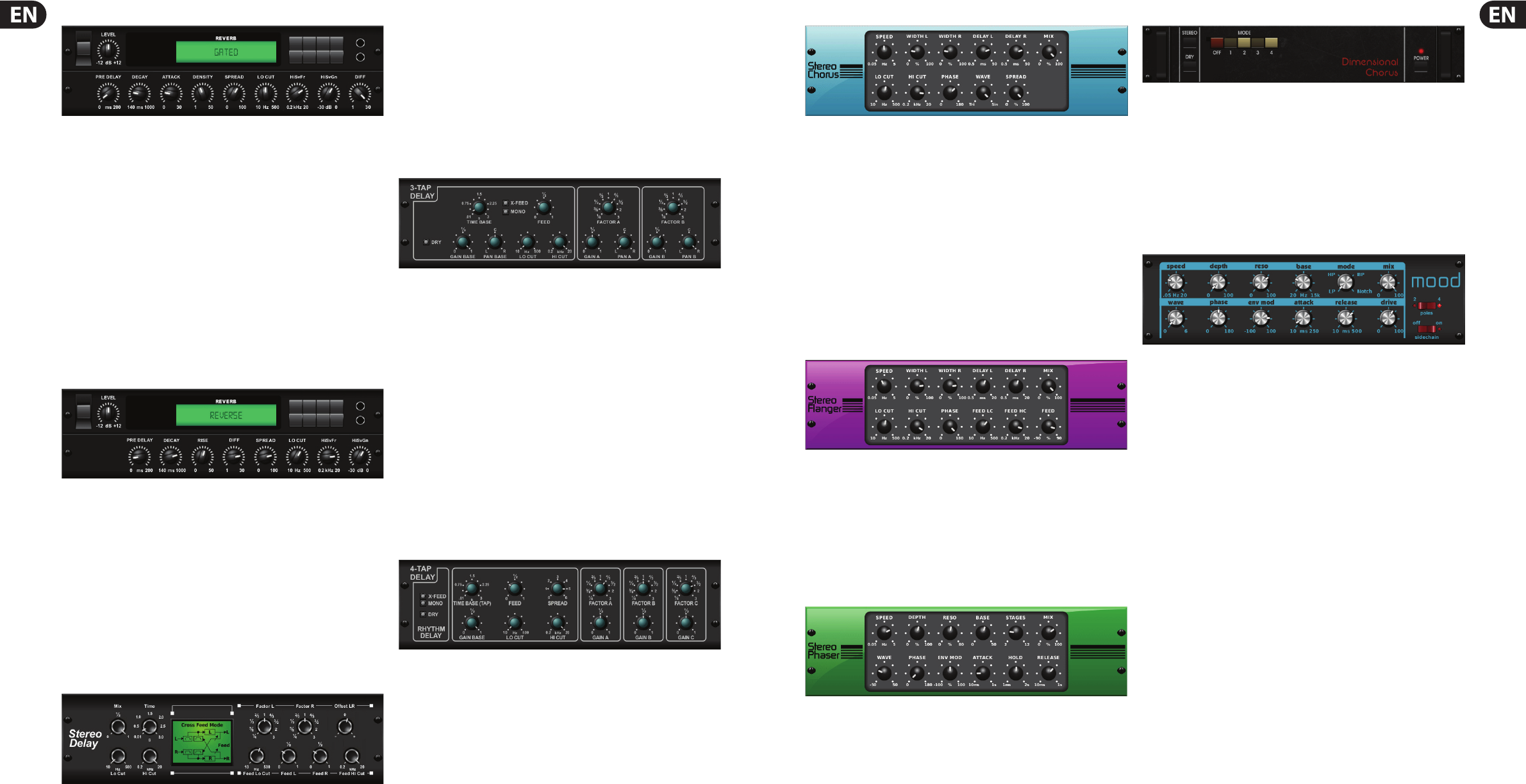
Gated Reverb
This e ect was originally achieved by combining a reverb with a noise gate.
Our gated reverb creates the same impression by a special shaping of the
reverb tail. Gated Reverb is especially e ective for creating a 1980’s-style
snare sound, or to enlarge the presence of a kick drum. Inspired by the
Lexicon 300/480L.
PRE DELAY controls the amount of time before the reverberation is heard
following the source signal. DECAY controls the amount of time it takes for the
reverb to dissipate. ATTACK controls how fast the re ection density builds up.
DENSITY shapes the reverb decay tail. The higher the density, the greater the
number of sound re ections. SPREAD controls how the re ection is distributed
through the reverb envelope. LEVEL controls the volume of the reverb.
The LO CUT push encoder sets the frequency beneath which the source signal
will not pass through the reverb. HiSvFr / HiSvGn push encoders adjust a high-
shelving lter and the input of the reverb e ect. DIFF(usion) controls the initial
re ection density.
Reverse Reverb
Reverse Reverb takes the trail of a reverb, turns it around, and places it in front
of the sound source.. Use the swelling crescendo of the Reverse Reverb to add an
ethereal quality to vocal and snare drum tracks. Inspired by the Lexicon 300/480L.
Adjusting the PRE DELAY push encoder adds up to 200 milliseconds before the
reverb follows the source signal. The DECAY push encoder adjusts the time it
takes for the reverb to completely dissipate. RISE controls how quickly the e ect
builds up. DIFF(usion) controls the initial re ection density. SPREAD controls
how the re ection is distributed through the reverb envelope. The LO CUT
push encoder sets the frequency beneath which the source signal will not pass
through the reverb. HiSvFr / HiSvGn push encoders adjust a high-shelving lter
and the input of the reverb e ect.
Stereo Delay
Stereo Delay provides independent control of left and right delay (echo) times,
and features high- and low-pass lters for enhanced tone-shaping of the
delayed signals. Use the Stereo Delay to give your mono signals a wide presence
in the stereo eld.
The MIX control lets you blend the source signal and the delayed signal. TIME
adjusts the master delay time up to three seconds. LO CUT adjusts the low
frequency cut, allowing lower frequencies to remain una ected by the delay.
HI CUT adjusts the high frequency cut, allowing higher frequencies to remain
una ected by the delay. FACTOR L sets the delay time on the left channel to
rhythmic fractions of the master delay time. FACTOR R sets the delay time on the
right channel to rhythmic fractions of the master delay time. OFFSET LR adds a
delay di erence between the left and right delayed signals. The FEED LO CUT/HI
CUT adjusts lters in the feedback paths. FEED L and FEED R control the amount
of feedback for the left and right channels. MODE selects the feedback mode:
• • ST sets normal feedback for both channels
• • X crosses feedback between left and right channels
• • M creates a mono mix within the feedback chain.
Triple Delay
Sometimes called a 3-Tap Delay, the Triple Delay provides three delay stages with
independent frequency, gain and pan controls. Create time-based echo e ects
with the triple delay to increase the sense of stereo separation.
TIME sets the master delay time, which is also the delay time for the rst
stage. GAIN BASE sets the gain level of the rst stage of the delay. PAN BASE
sets the position of the rst delay stage in the stereo eld. LO CUT sets the
frequency at which the source signal can begin passing through the delay.
HI CUT sets the frequency at which the source signal can no longer pass through
the delay. X-FEED indicates that stereo cross-feedback of the delayed signals
is active. MONO activates a mono mix of both channels for the delay input.
FEEDBACK adjusts the amount of feedback.
FACTOR A controls the amount of delay time in the second stage of the delay. GAIN
A controls the gain in the second stage of the delay. PAN A sets the position of the
second stage of the delay in the stereo eld. FACTOR B controls the amount of delay
time in the third stage of the delay. GAIN B controls the gain in the third stage of
the delay. PAN B sets the position of the third stage of the delay in the stereo eld.
Rhythm Delay
The Rhythm Delay, or 4-Tap Delay, provides four delay stages with
independent frequency, gain and pan controls. Create time-based echo e ects
with the triple delay to increase the sense of stereo separation.
TIME sets the master delay time, which is also the delay time for the rst stage.
GAIN BASE sets the gain level of the rst stage of the delay. LO CUT sets the
frequency at which the source signal can begin passing through the delay.
HI CUT sets the frequency at which the source signal can no longer pass through
the delay. X-FEED indicates that stereo cross-feedback of the delayed signals
is active. MONO activates a mono mix of both channels for the delay input.
FEEDBACK adjusts the amount of feedback. SPREAD adjusts the perceived
stereo placing of the echoes.
FACTOR A controls the amount of delay time in the second stage of the delay.
GAIN A controls the gain in the second stage of the delay. FACTOR B controls
the amount of delay time in the third stage of the delay. GAIN B controls the
gain in the third stage of the delay. FACTOR C controls the amount of delay time
in the fourth stage of the delay. GAIN C controls the gain in the fourth stage of
the delay.
Stereo Chorus
Chorus samples the input, slightly detunes it and mixes it with the original
signal to produce a somewhat thicker, shimmering sound. Use it to thicken up
background vocals, or to double the sound of brass and woodwind instruments.
Whereas DELAY L / R set the total amount of delay for the left and right
channels, WIDTH L / R determines the amount of modulated delay taken from
either the left or right channels. SPEED sets the modulation speed, MIX adjusts
the balance of dry and wet signals. You can further sculpt the sound by trimming
some of the low- and high-end of the a ected signal with the LO CUT and
HI CUT push encoders. Additionally the PHASE push encoder can tweak the
phase o set of the LFO between left and right channels, and the SPREAD push
encoder adjusts how much of the left channel is mixed into the right, and vice
versa. Finally the WAVE push encoder blends between the ‘Danish’ style digital
triangular chorus sound and the classic analogue sine wave.
Stereo Flanger
The Flanger emulates the phase-shifting sound (comb- ltering) originally created by
applying pressure against the ange of the reel on a tape recorder. This e ect creates
a unique ‘wobbly’ sound that is quite dramatic when used on vocals and instruments.
The controls of this e ect are nearly identical to the controls on the Chorus e ect
block. Additionally, the FEEDBACK can be adjusted with positive and negative
amounts, and also band-limited with the FEED HC (high-cut) and FEED LC
(low cut) push encoders.
Stereo Phaser
A Stereo Phaser, or phase shaper, applies multiple STAGES of modulated lters to
the input signal to create a ‘notch’ in the frequency response, and then applies a
MIX with the original for a ‘swirling’ e ect. Use the M32’s Stereo Phaser to add a
‘spaced-out’ sound to vocal or instrumental tracks.
SPEED sets the LFO rate and DEPTH sets the LFO modulation depth.
The BASE push encoder adjusts the frequency range of the modulation lters.
The resonance is adjusted with the RESO push encoder. STAGES determines the
number of times the audio signal is processed by the e ect. MIX determines how
much of the a ected signal is present in the output audio.
The WAVE push encoder shapes the symmetry of the LFO waveform, and
PHASE dials in an LFO phase di erence between the left and right channels. The
modulation source can also be the signal envelope, which produces vowel-like
opening and closing tones. The ENV MOD push encoder adjusts how much of this
e ect takes place (positive and negative modulation is possible), and the ATTACK,
HOLD and RELEASE push encoders all tailor the response of this feature.
Dimension-C
Chorus samples the input, slightly detunes it and mixes it with the original
signal to produce a somewhat thicker, shimmering sound. Use it to thicken up
background vocals, or to double the sound of brass and woodwind instruments.
Inspired by the Roland Dimension D.
Turning the rst push encoder to toggle the output signal between Mono
and STereo. Pressing the rst encoder turns the e ect on or o . Pressing the
second encoder turns dry mode on or o . Pressing the third, fourth or fth push
encoders engages the chorus e ect with increasing intensity.
Mood Filter
The Mood Filter uses an LFO generator and an auto-envelope generator to
control a VCF (voltage-control lter), as well as a side-chain function, where
the channel B signal controls the envelope of channel A. When applied to
electronic instruments, the Mood Filter can be used to emulate the natural sound
of acoustic instruments. Inspired by the MiniMoog.
This lter can be modulated with the signal’s envelope using the ENV MOD (with
positive and negative amounts), ATTACK and
RELEASE push encoders, or the LFO
can modulate the lter. The WAVE push encoder selects between seven di erent
waveforms - triangular, sine, saw plus, saw minus, ramp, square and random.
The PHASE can be o set by up to 180°. The SPEED push encoder adjusts the
rate of the LFO, and DEPTH adjusts the amount of LFO modulation. Adjust the
resonance of the lter until self-oscillation with the RESO(nance) push encoder.
BASE adjusts the range of the lter from 20 Hz to 15 kHz. The MODE switch
selects between low-pass (LP), high-pass (HP), band-pass (BP) and Notch.
Use the MIX push encoder to blend the a ected signal with the dry sound.
With the 4 POLE switch engaged there will be a steeper slope than the 2 POLE
setting. The DRIVE push encoder adjusts the level, and can also introduce an
overdrive e ect (as with real analogue lters) if pushed hard. In Side-chain mode,
only the left input signal is processed and fed to both outputs. The envelope of
the right input signal can be used as a modulation source. Applying the SIDE
CHAIN function ensures that the parameters of the e ect are changed based on
an external stimulus signal.