on sensitive carbon surfaces, preventing damage to fi-
bers
(e)
or the cracking of the carbon substructure.
The headset
The headset
(f)
connects the fork to the frame, but
allows it to move freely. It must afford virtually no re-
sistance to moving, if your MERIDA road bike is to go
straight, stabilizing itself as it runs. The shocks caused
by uneven road surfaces expose the headset to consid-
erable levels of stress. In this way it can become loose
and maladjusted.
G
Riding the bike with a loose headset greatly
increases the stress on the fork and the bear-
ings. This can lead to damage to the fork. Risk
of an accident!
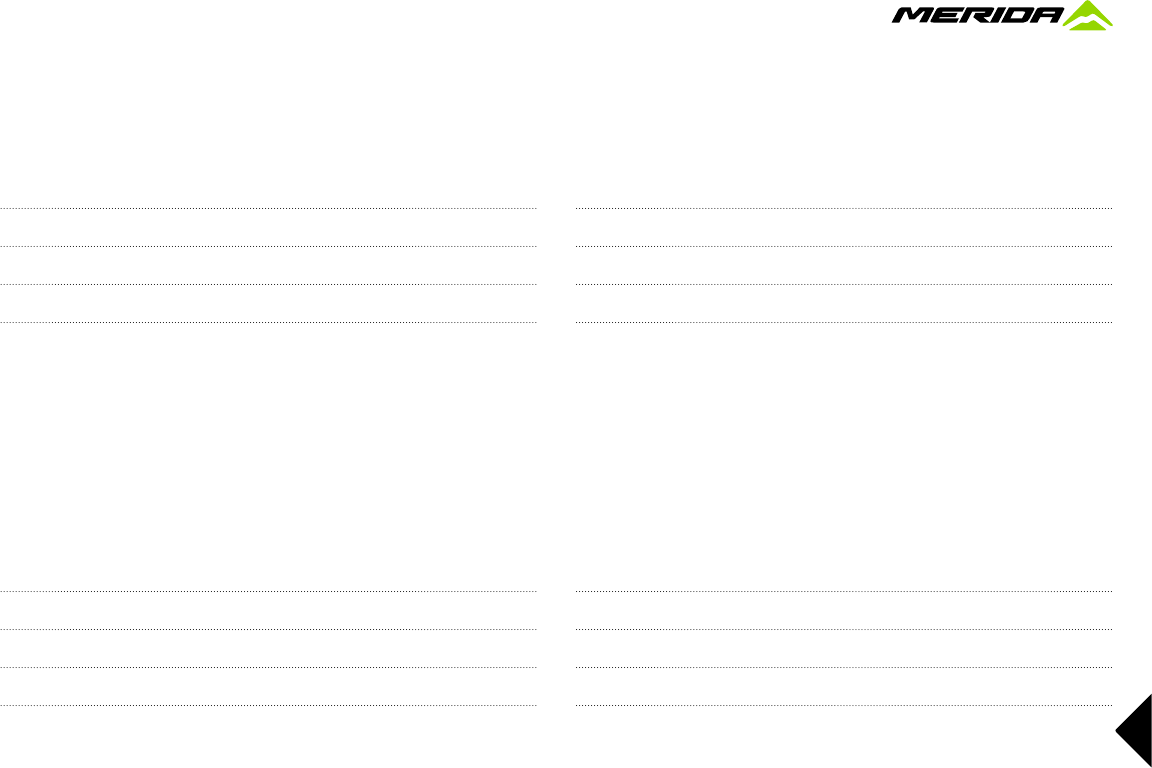
Checking and readjusting
Check the headset for play by placing your fingers
around the upper head tube race
(g)
.
Bring your weight to bear on the saddle, pull the front
brakes with your other hand and push your MERIDA
road bike firmly back and forth with the wheel remaining
on the ground
(h)
. If the bearing has play, you will feel
the upper head tube race moving in jerks relative to the
lower head tube race - visible as a small gap in between
the head tube races.
To check the bearing for ease of running, lift the frame
until the front wheel is suspended in the air. The handle-
bars should turn from far left to far right without feeling
roughness or tightness at any point.
66
a
b
c
d
With a gentle tap on the handlebars the fork should turn
easily from the middle position. If you face any prob-
lems during the test, contact your MERIDA dealer.
G
Adjusting the headset requires a certain
amount of experience and should therefore
be left to your MERIDA dealer.
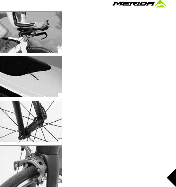
Threadless headsets – Aheadset
®
This headset system is characterized by the fact that the
stem is not in the fork steerer tube but clamps it from
outside. Hence the stem is an important constituent part
of the headset. Clamping it also sets the adjustment. You
generally only need one or two Allen keys and a torque
wrench to adjust an Aheadset
®
. Release the clamping
bolt(s) located on the side of the stem by one to two
turns
(a)
. Gently tighten the countersunk adjusting bolt
on top a little, e.g. by a quarter turn
(b)
, by using an
Allen key.
Align the stem so that the handlebars are not slanted.
Make sure the front wheel is in line with the top tube and
the stem. Tighten up the stem clamping screws. Use a
torque wrench and never exceed the maximum torque
values! You will find the prescribed values in the chapter
“Recommended torque settings”, directly on the com-
ponents and/or in the operating instructions of the com-
ponent manufacturers on this MERIDA CD-ROM.
Check the headset for play as described above
(c)
. Take
care not to tighten the bearing too much, as this could
easily destroy it.
G
Bear in mind that by overtightening the bolts
the stem can crush the steerer tube. In par-
ticular, models with a carbon fork steerer
tube react very sensitively to overloading as a result
of overtightening the shaft clamp at the stem. Risk of
breakage! Make sure the clamping area is absolutely
free of grease when any of the clamping faces is made
of carbon. Use carbon assembly paste in the clamping
areas to ensure maximum clamping.
G
Check the secure seat of the stem by taking
the front wheel between your legs and trying
to turn the handlebars and stem relative to
the wheel
(d)
. A loose stem can cause bad accidents.
G
Never change the preloading mechanism in
the inside of the fork steerer tube. Never in-
stall a star nut in carbon fork steerer tubes.
A
Do not overtighten the upper bolt, it only
serves to adjust the headset play.
i
There can be several reasons why the bear-
ings cannot be adjusted. If you are not abso-
lutely sure, ask your MERIDA dealer for help.
67
e
f
g
h
Things worth knowing about your
MERIDA road bike
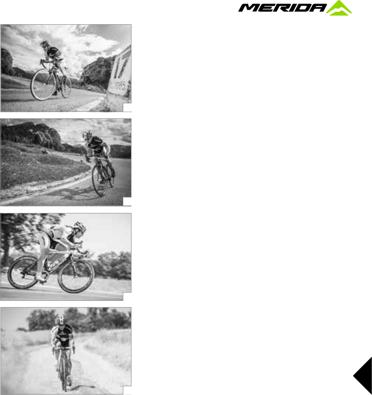
Cycling helmets and glasses
Cycling helmets are a must when riding a bike. Your
MERIDA dealer has a variety of styles and sizes.
Verify that the helmet complies with the test standard
DIN EN 1078. Cycling helmets are only approved for use
during cycling. Observe the manufacturer’s instructions.
G
Never ride without a helmet
(e+f)
! But re-
member that even the safest helmet is use-
less unless it fits properly and is correctly
adjusted and fastened.
In addition to a cycling helmet and suitable clothing,
cycling glasses are absolutely essential when you are
riding your MERIDA road bike.
They do not only protect your eyes from the sun and the
wind, but also keep out flies and other impurities that
may impede your vision when they fly into your eyes.
Risk of an accident!
Good cycling glasses must fit closely against your face
so that the wind does not get into your eyes from the
side. There are a great many different models, for ex-
ample, without tinting and UV protection, which can be
worn at night or in twilight conditions, or glasses with a
high level of UV protection that you should wear if the
sun is stronger.
Your MERIDA dealer has a wide range of cycling glasses
available and will be pleased to advise you!
Clothing
Cycling trousers
(g)
are essential if you want to sit com-
fortably. These close-fitting trousers have special pad-
ding in the seat. They have no seams that can press
into you and they do not form folds. Cycling trousers are
therefore designed to be worn next to the skin.
Since sporty cycling will soon bring you out in a sweat,
a jersey made of synthetic materials is ideal
(h)
. The fi-
bers themselves do not take up any moisture but instead
wick the sweat away from the skin up to the surface of
the materials and thus prevent you getting cold from
the cool wind produced by your speed. On longer tours
you should in addition have suitable protection against
the rain. Your MERIDA dealer will be glad to help you
choose the right equipment.
68
a
b
c
d
G
Never ride with wide-cut trousers or skirts
that might get caught in the spokes, chain or
chainwheels. To avoid any such mishap, use
suitable clips or straps, if necessary.
G
For increased visibility to other road users
be sure to wear striking and bright-colored
clothing!
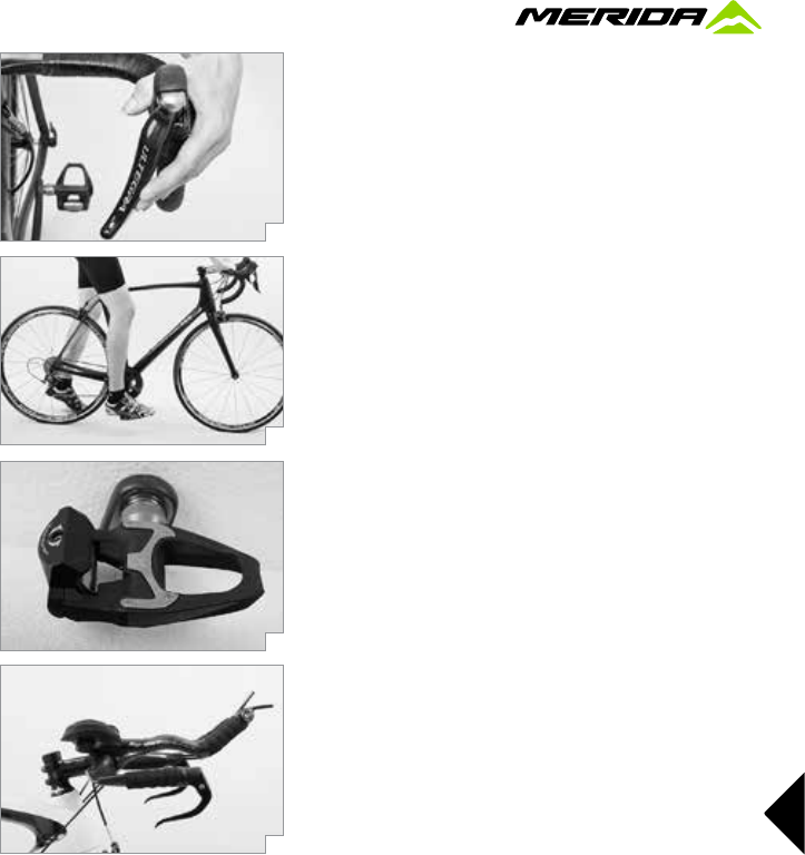
The pedals and the shoes
Cycling shoes
(a)
should be made of solid material
to provide firm support for your feet. In addition, they
should have a stiff sole so that the pedal cannot press
through. The sole should not be too wide in the area of
the heels, as the rear stays or the crank will otherwise
get in the way of your pedaling. This will prevent your
feet from assuming a natural position when pedaling
and may cause knee pain in the long run.
Special cycling shoes are obligatory if your MERIDA
road bike is equipped with clipless pedals. With these
shoes cleats are fixed to the sole. They give you a firm
connection between shoe and pedal and allow depend-
ing on the model an acceptable walking position.
The main advantage is that these clipless pedals
(b)
pre-
vent your feet from slipping off when pedaling fast. They
enable you not only to push but also to pull the pedals.
This makes it easier to pedal fluidly and considerably
improves the transmission of the force as opposed to
pedals with an open pedal cage.
The usual way to engage with the pedal is to turn it from
the lowest position of the crank to the horizontal using
the tip of the cleat and push down on the back of it.
Normally, the shoe engages with the pedal with a click
which you will hear and feel clearly.
The release force of clipless pedals is adjusted by means
of an Allen key
(c)
. If there are any creaking or squeak-
ing noises occurring, some grease applied to the con-
tact points will solve the problem in most cases. These
noises as well as lateral play of the shoe on the pedal
can, however, be also signs of wear. Check the cleats at
regular intervals.
G
Make sure the fastening bolts of the cleats
are properly tightened, as you will find it al-
most impossible to disengage your shoe from
the pedal, if the cleat is loose. Risk of an accident!
G
Taking up the pedals, engaging and disen-
gaging the shoes should first be practiced in
stationary. Later you can refine your tech-
nique in a place clear of traffic
(d)
.
G
Only use clipless pedals allowing you to en-
gage and disengage smoothly. A defective
pedal or a badly worn cleat can make the
shoe disengage from the pedal. Unclipping the shoe
from the pedal is sometimes very difficult or even im-
possible. In both cases, there is the danger of an ac-
cident!
69
e
f
g
h
G
Make sure pedals and shoe soles are always
clear of mud and other impurities
(e)
and
grease the lock-in mechanism with lubricant
at regular intervals.
G
Most cycling shoes with cleats are only suit-
able for walking to a limited extent. As the
cleats, in particular when mounted to road
bike shoes, are thicker than the sole, they provide less
grip even on a non-slip ground. Be particularly careful.
i
Ask your MERIDA dealer for advice about
the different shoe and pedal models. Cycling
shoes come in various styles for specific uses.
i
Read the operating instructions of the pedal
manufacturer on this MERIDA CD-ROM.
Accessories
In purchasing your MERIDA road bike you laid the foun-
dation for many years and miles of enjoyable cycling.
Whatever you are planning to do with your MERIDA
road bike, be sure to have proper equipment and to keep
a few tips in mind. Your MERIDA dealer has a variety of
useful accessories on offer enhancing both your safety
and convenience.
Your MERIDA road bike can be fitted with various kinds
of accessories. Make sure to observe the requirements
according to the traffic regulations in your country and
of the DIN EN standards.
Any retrofitted part must be compatible with your
MERIDA road bike. If you are in doubt or if you have any
questions, contact your MERIDA dealer.
G
Improper accessories may change the qual-
ities of your MERIDA road bike and even
cause an accident. Therefore, before fitting
any accessories contact your MERIDA dealer and ob-
serve the instructions regarding the intended use of
your MERIDA road bike.
G
Retrofitted accessories, such as mudguards,
pannier racks etc. can impair the functioning
of your MERIDA road bike. Ask your MERIDA
dealer for advice before mounting any kind of accesso-
ries to your bike.
A
Before buying any additional bells or lighting
accessories
(f)
, inform yourself thoroughly
whether they are permitted and tested and
accordingly approved for use on public roads. Make
sure additional battery/accumulator-powered lamps
(g)
are marked with the wavy line and the letter “K”.
Bicycle locks
Do not forget to take a high quality D-lock
(h)
or chain
lock with you on your ride. The only way to effectively
protect your MERIDA road bike against theft is to lock it
to an immovable object.
70
a
b
c
d
Puncture kit
The most important accessories for a successful cycle
tour are a tire pump and a small tool kit. The tool kit
should include two plastic tire levers, the most com-
monly used Allen keys, a spare tube, a tire repair kit,
your mobile phone, if necessary, and a little cash
(a)
.
In this way you will be well prepared in the event of a
puncture or some other mishap.
Cycle computers
There are electronic computers that show your current
and average speed, your daily and annual mileage as
well as the duration of the present ride
(b)
. Real de luxe
models also give the highest speed achieved, differenc-
es in elevation, your cadence or your heart rate.
Today, there are global positioning systems (GPS) and
specific power meters for optimal training on the market
which are compatible with your MERIDA road bike.
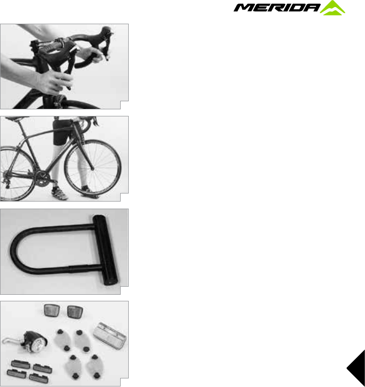
Aero or triathlon/time trial bars
Before you mount aero or triathlon/time trial bars
(c)
on
your MERIDA road bike, it is essential to find out first
whether the handlebars or a corresponding attachment
for use with your handlebars and stem are approved.
i
Read the operating instructions of the handle-
bar and stem manufacturers on this MERIDA
CD-ROM. If you are in doubt or if you have
any questions, contact your MERIDA dealer!
Mudguards/wheel protections
If you want to mount mudguards on your MERIDA road
bike, ask your MERIDA dealer for advice. There are
removable mudguards
(d)
, also referred to as clip-on
mudguards, as well as firmly attached models that pro-
vide more protection.
Retrofittable mudguards for a fix fastening are usually
made of plastics and are secured in the correct position
by means of additional stays. The length of the stay is
perfect when the bottom edge of the mudguard runs at
an approx. distance of 15 mm in parallel to the tire.
For safety reasons the front wheel stays must have
security fastenings. They prevent the tire from being
blocked by impurities taken up by the front wheel from
the ground. In this case the security fastening frees the
stay and hereby prevents a possible accident. The plug
connection can easily be refastened.
G
Damaged mudguards should be replaced in
any case. Risk of an accident!
71
e
f
g
h
Transporting baggage
There are various ways of carrying baggage on your
MERIDA road bike. Your choice will primarily depend on
the weight and volume of the baggage. Using a bicycle
rucksack
(e)
is a convenient way of transporting bag-
gage on a bike and therefore recommendable. You can
also use pannier racks
(f)
or handlebar bags, but some
MERIDA road bike models do not allow the mounting of
these accessories. If you are in doubt or if you have any
questions, contact your MERIDA dealer.
G
If necessary, do not overload your MERIDA
road bike (see “Bike card”) and also observe
the maximum load capacity marked on or im-
pressed in your pannier rack.
A
Baggage generally changes the riding char-
acteristics of your MERIDA road bike and
increases your stopping distance! Practice
riding a loaded road bike in a place clear of traffic.
Taking children with you
MERIDA road or triathlon bikes are mainly not designed
for taking children on them. This applies in particular to
those with very light frames. Ask your MERIDA dealer
for advice and have a look at the bike card. Also read the
instructions of the child seat or the trailer which must be
supplied by the manufacturers with the products.
G
If you want to hitch a trailer
(g)
or a kids’ tan-
dem bike/trailer system to your MERIDA road
bike or if you want to mount a child seat
(h)
on it, check whether the road bike is designed accord-
ingly. Have a look at the bike card or ask your MERIDA
dealer for advice.
72
a
b
c
d
Transporting the MERIDA bike
By car
Nearly every car accessory dealer and car company of-
fers carrier systems
(a)
that allow the transport of a bike
without disassembly.
The usual design involves rails fixed to the roof of the
car onto which the bikes are fixed with clamps gripping
the down tubes. This can, however, result in irreparable
damage to the frame. High-end, very thin-walled alumi-
num or carbon fiber frames are particularly susceptible
to this kind of damage. Due to the material properties
of carbon fiber, you may not see severe damage at first
sight, but it can result in an unforeseeable severe acci-
dent at a later date. There are, however, special suitable
models available in the car accessory trade.
Rear carriers are becoming more and more popular.
Their big advantage over roof carriers is that you do not
have to lift up the bike so high to attach it. Make sure the
clamps used do not cause any damage to the fork or
frame. Risk of breakage!
Whatever system you opt for, make sure it complies
with the relevant safety standards of your country, such
as the GS mark!
Read the operating instructions of your bicycle carrier
and comply with the maximum load capacity and rec-
ommended or prescribed driving speed. If applicable,
comply with the required supporting load on the trailer
hitch.
G
Do not buy a carrier on which your MERIDA
road bike has to be mounted upside down,
i.e. with the handlebars and saddle fixed
face down to the carrier. This way of fastening the bike
exposes handlebars, stem, saddle and seat post to ex-
treme stress during transport. Do not opt for a carrier
system with crank arm fit. Risk of breakage!
G
Check whether your MERIDA road bike is
properly fastened before and at regular inter-
vals during the journey. A bike that detaches
from the carrier system may endanger other road users.
G
Always secure your MERIDA road bike or
bike components when putting it/them into
the interior of your car
(b+c)
. Parts shifting
around can impair your safety.
A
Most clamps are a potential source of dam-
age to large-diameter frame tubes
(d)
that
are not designed to be fixed in such clamps!
Do not use such systems with carbon frames!
73
e
f
g
h
A
Please make sure the lights and the number
plate of your car are not hidden from view.
For some carriers, a second exterior rear view
mirror is required by the road traffic regulations.
A
Make sure to remove all parts of your bike
(tools, pannier bags, etc.) which may come
loose during transport.
A
Do not store any traveling bags, suitcases or
other objects on your MERIDA road bike in-
side your car.
A
If your bike has disc brakes, be sure to mount
the safety locks
(e)
before transporting your
MERIDA cyclo-cross bike with the wheels
dismounted.
A
Pull the brake levers and secure them with a
strong rubber band
(f)
.
A
Bear in mind that your car may have a great-
er overall height or width. Measure the over-
all height and place a sign stating the height
somewhere in the cockpit or on the steering wheel so
that it can be easily seen.
By public transport
In cities the regulations for taking MERIDA bikes by
public transport differ
(g+h)
. There are e.g. some places
where you are only allowed to travel with your MERIDA
road bike during off-peak hours and with an additional
bicycle ticket. Inform yourself in time about the regula-
tions of carrying the bike before you start the trip!
In some trains you can stow your MERIDA road bike in
multi-purpose compartments. They are often at the front
or end of a train and marked with a bicycle sign.
i
Before you start your trip inform yourself in
time about the conditions of carriage and also
observe the regulations and rules about bicy-
cle transport in the countries through which you intend
to travel.
74
a
b
c
d
By plane
If you want to take your MERIDA road bike with you
when you go on a trip by plane, pack it in an appro-
priate bicycle suitcase
(a)
or in a bicycle cardboard box
that you can obtain from your MERIDA dealer. Special
bicycle bags often do not provide sufficient protection for
your MERIDA road bike.
Pack the wheels (in particular carbon wheels) in spe-
cial wheel bags to protect them inside the suitcase or
cardboard box. Do not forget to take the necessary tools,
a torque wrench and bits, carbon assembly paste and
these operating instructions with you to be able to as-
semble your MERIDA road bike and to get it ready for
use at your destination.
A
If your MERIDA cyclo-cross bike has disc
brakes, be sure to mount the safety locks
before transporting the bike with the wheels
dismounted.
A
Pull the brake levers and secure them with a
strong rubber band.
General notes on care and servicing
Maintenance and servicing
Your MERIDA dealer will have assembled and adjusted
your MERIDA bike ready for use when you come to col-
lect it. Nevertheless, your MERIDA bike needs regular
servicing
(b)
. Have your local MERIDA dealer do the
scheduled maintenance work. This is the only way to
ensure that all components function safely and reliably
for many miles.
The bike will be due for its first service after 100 to 300
kilometers, 5 to 15 hours of initial use or four to six
weeks. The bedding-in phase typically involves spokes
slightly losing tension or gears coming out of adjust-
ment, so there is every reason to have your MERIDA
dealer service the MERIDA bike at this stage. This bed-
ding-in process is unavoidable. Therefore, remember to
make an appointment with your MERIDA bike dealer to
have your new MERIDA bike inspected. This first service
is very important for both functioning and durability of
your MERIDA bike.
It is advisable to have your MERIDA bike serviced reg-
ularly by your MERIDA dealer after the bedding-in
phase. If you ride a great deal on poor road surfaces or
cross-country, it will require correspondingly shorter ser-
vice periods. The off-season during the winter months
is a very good time to take your MERIDA bike to your
MERIDA dealer for the annual inspection, as they will
have plenty of time for you and for servicing.
75
e
f
g
h
The intended use of the MERIDA bike includes regular
servicing and the replacement of wearing parts in time,
e.g. chains, brake pads
(c)
or Bowden and brake cables
(d)
, and therefore has an influence on the warranty and
the guarantee, as well.
For more information see the chapter “Service and
maintenance schedule”.
G
Servicing and repairs are jobs best left to
your MERIDA dealer. If you have your bike
serviced by anyone else than an expert, you
run the risk that parts of your MERIDA bike will fail.
Risk of an accident! When working on your MERIDA
bike, restrict yourself to jobs for which you have the
suitable tools, e.g. a torque wrench, and the necessary
knowledge.
G
If a component needs to be replaced, make
it a rule to only use original spare parts
(e)
.
Wearing parts of other manufacturers, e.g.
brake pads or tires that are not of identical dimension,
may render your MERIDA bike unsafe. Risk of an ac-
cident!
Cleaning and caring for your MERIDA bike
Dried sweat, dirt and salt from riding during the winter
or in sea air can harm your MERIDA bike. You should
therefore make it a habit of cleaning all components at
regular intervals.
Avoid cleaning your bike with a high-pressure clean-
er. The high-pressure jet is likely to enter bearings by
passing through the seals and dilute the lubricants
hereby increasing the friction. This destroys and im-
pairs the functioning of the bearing races in the long
term. High-pressure jets are also likely to remove
frame stickers.
A much more gentle way of cleaning your bike is with a
low-pressure water jet or a bucket of water and a sponge
or a large brush. Cleaning your bike by hand has anoth-
er positive side-effect: you may discover defects in the
paint
(f)
as well as worn or defective components at an
early stage.
Check the chain for wear
(g)
and relubricate
(h)
after
cleaning and drying (see the chapter “Chain – care and
wear” and the instructions of the component manufac-
turers on this MERIDA CD-ROM). Wipe dry the sliding
surfaces of the suspension fork and the rear shock and
apply special spray. Apply a coat of standard hard wax
on painted, metal and carbon surfaces (except from
brake surfaces and brake discs). Polish the waxed sur-
faces after drying to give them a nice shine.
76
a
b
c
d
G
Keep cleaning agents and chain oil clear of
the brake pads, brake discs and rim sides
(braking surfaces). Otherwise the brake could
fail. Never grease or lubricate the clamping areas of a
frame made of carbon, e.g. handlebars, stem, seat post
and seat tube. Once greased, carbon components may
never again ensure reliable clamping!
G
While cleaning, watch out for cracks,
scratches, dents as well as deformed or dis-
colored material. Have defective components
replaced immediately and touch up paint defects. If you
are in doubt or if you have any questions, contact your
MERIDA dealer.
A
Only use petroleum-based solvents for
cleaning tough oil or grease stains from paint
and carbon surfaces. Never use degreasing
agents containing acetone, methyl chloride or the like,
or solvent-containing, non-neutral or chemical cleaning
agents that could attack the surface!
A
Do not clean your MERIDA bike with a
high-pressure cleaner or a water jet and if
you do, be sure to keep it at a distance. Do
not aim at the bearings.
Safekeeping and storing your MERIDA bike
If you regularly look after your MERIDA bike during the
season, you will not need to take any special measures
when storing it for a short time, apart from securing it
against theft. Store your bike in a dry, well aerated place.
If you want to store your MERIDA bike for a longer peri-
od of time, e.g. over the winter months, please observe
the following things: Inflated inner tubes tend to gradu-
ally lose air when the bike is not used for a long time.
If your MERIDA bike is left standing on flat tires for an
extended period, this can cause damage to the struc-
ture of the tires. It is therefore better to hang the wheels
or the entire MERIDA bike
(a)
or to check the tire pres-
sure regularly
(b)
. Clean your MERIDA bike and protect
it against corrosion. Your MERIDA dealer has special
cleaning agents, e.g. spray wax.
Remove the seat post
(c)
and let moisture that may
have entered dry. Spray a little finely atomized oil into
the metal seat tube. However, do not apply oil in a car-
bon seat tube. Shift the gear to the smallest chainwheel
and the smallest sprocket
(d)
. This relaxes the cables
and the springs.
i
There are hardly any waiting times at your
MERIDA dealer during the winter months. In
addition, many of the MERIDA dealers offer
an annual check-up at a special price. Benefit from the
idle time and ask your MERIDA dealer to do the sched-
uled maintenance work!
77
Service and maintenance schedule
It is advisable to have your MERIDA bike serviced regularly after the bedding-in phase. The schedule given in the table below is a rough guide for cyclists who
ride their bike between 2,000 and 3,000 km or 100 to 150 hours of use a year.
If you consistently ride more or if you ride a great deal on poor road surfaces, the service periods will shorten accordingly.
Component What to do Before every ride Monthly Annually Other
Lighting Check function, if necessary x
Tires Check pressure x
Check tread and side walls x
Brakes (rim brakes) Check lever travel, wear of brake pads, position of pads relative to rim; x
test brakes in stationary
Brakes (mechanical disc brakes) Lever travel, brake pads and test brakes in stationary x
Brakes, brake pads (rim brakes) Clean x
Brake cables, pads hoses Visual inspection x
Brakes (disc brakes) Check lever travel, wear of brake pads, check seals, x
test brakes in stationary
Replace liquid (DOT-liquids) •
Rims (of rim brakes) Check thickness, replace if necessary • after 2nd set of
brake pads at the latest
Fork Check and replace, if necessary • at least every 2 years
Bottom bracket Check for bearing play x
Dismount and regrease (cups) •
Chain Check and grease, if necessary x
Check wear, replace, if necessary, derailleur gears • after 1,000 km or
or 50 hours of use
Crank Check and retighten, if necessary x
Painted/anodized/carbon surfaces Impregnate x at least every
6 months
78
Component What to do Before every ride Monthly Annually Other
Wheels/spokes Check for trueness and tension x
True or retighten • if necessary
Handlebars and stem Check and replace, if necessary • at the latest every
(aluminum and carbon) 2 years
Headset Check for bearing play x
Regrease •
Metal surfaces Polish (except: Rim sides of rim brakes, rotors) x at least every
6 months
Hubs Check for bearing play x
Regrease •
Pedals (all) Check for bearing play x
Pedals (clipless) Clean and grease locking mechanism x
Seat post/stem Check bolts x
Dismount and re-lubricate
Carbon: new assembly paste (no grease!) •
Front/rear derailleur Clean and grease x
Quick-releases Check seat x
Bolts and nuts (mudguards etc.) Check and retighten, if necessary x
Valves Check seat x
Cables (gears/brakes) Disassemble and regrease •
If you have a certain degree of mechanical skills, experience and suitable tools, such as a torque wrench, you should be able to do the checks marked x by
yourself. If you come across any defects, take appropriate measures without delay. If you are in doubt or if you have any questions, contact your MERIDA
dealer.
Jobs marked • are best left to your MERIDA dealer.
i
For your own safety, bring your MERIDA bike to your MERIDA bike dealer for its first inspection after 100 to 300 kilometers, 5 to 15 hours of initial
use or four to six weeks, and at the very latest after three months.
79
Recommended torque settings
All bolted connections of the bike components have to be tightened carefully and checked regularly to ensure the safe and reliable operation of the MERIDA
bike. This is best done with a torque wrench that disengages at the desired torque value or a click-type torque wrench. Tighten carefully by approaching the
prescribed maximum torque value in small steps (0.5 Nm increments) and check the proper fit of the component in between. Never exceed the maximum
torque value indicated by the manufacturer!
Where no maximum torque setting is given start with 2 Nm. Observe the indicated values and observe the values on the components and/or in the operating
instructions of the component manufacturers on this MERIDA CD-ROM.
Component Bolted connections Shimano
1
(Nm) SRAM/Avid
2
(Nm) Campagnolo
3
(Nm)
Rear derailleur Mount (on frame/derailleur hanger) 8 - 10 5 - 7 15
Cable clamp 5 - 7 5 - 7 6
Pulley wheels 2.5 - 3 2.7
Front derailleur Mount on frame 5 - 7 5 - 7 (clamp) 5 (clamp)
5 - 7 - (direct mounting) 7 (direct mounting)
Cable clamp 6 - 7 5 5
Brake levers/shifter units Mount on handlebars 6 - 8 6 - 8 10
Flatbar 6
Hub Quick-release lever 5 - 7.5
Counter nut for bearing adjustment with
quick-release hubs 15 - 17
Sprocket cluster lock ring 30 - 50 40 40 (11-speed)
Gebruikershandleiding.com neemt misbruik van zijn services uitermate serieus. U kunt hieronder aangeven waarom deze vraag ongepast is. Wij controleren de vraag en zonodig wordt deze verwijderd.
Product:
Spelregels forum
Om tot zinvolle vragen te komen hanteren wij de volgende spelregels:
lees eerst de handleiding door;
controleer of uw vraag al eerder door iemand anders is gesteld;
probeer uw vraag zo duidelijk mogelijk te stellen;
heeft u een probleem en al geprobeerd om dit op te lossen, vermeld dit erbij aub;
heeft u een oplossing gekregen van een bezoeker dan horen wij dat graag in dit forum;
wilt u een reactie geven op een vraag of antwoord, gebruik dan niet dit formulier maar klik op de knop 'reageer op deze vraag';
uw vraag wordt direct op de website gezet; vermijd daarom persoonlijke gegevens in te vullen;
Belangrijk! Als er een antwoord wordt gegeven op uw vraag, dan is het voor de gever van het antwoord nuttig om te weten als u er wel (of niet) mee geholpen bent! Wij vragen u dus ook te reageren op een antwoord.
Belangrijk! Antwoorden worden ook per e-mail naar abonnees gestuurd. Laat uw emailadres achter op deze site, zodat u op de hoogte blijft. U krijgt dan ook andere vragen en antwoorden te zien.
Abonneren
Abonneer u voor het ontvangen van emails voor uw Merida Road Bike bij:
nieuwe vragen en antwoorden
nieuwe handleidingen
U ontvangt een email met instructies om u voor één of beide opties in te schrijven.
Ontvang uw handleiding per email
Vul uw emailadres in en ontvang de handleiding van Merida Road Bike in de taal/talen: Engels als bijlage per email.
De handleiding is 2,87 mb groot.
U ontvangt de handleiding per email binnen enkele minuten. Als u geen email heeft ontvangen, dan heeft u waarschijnlijk een verkeerd emailadres ingevuld of is uw mailbox te vol. Daarnaast kan het zijn dat uw internetprovider een maximum heeft aan de grootte per email. Omdat hier een handleiding wordt meegestuurd, kan het voorkomen dat de email groter is dan toegestaan bij uw provider.
Uw handleiding is per email verstuurd. Controleer uw email
Als u niet binnen een kwartier uw email met handleiding ontvangen heeft, kan het zijn dat u een verkeerd emailadres heeft ingevuld of dat uw emailprovider een maximum grootte per email heeft ingesteld die kleiner is dan de grootte van de handleiding.
Er is een email naar u verstuurd om uw inschrijving definitief te maken.
Controleer uw email en volg de aanwijzingen op om uw inschrijving definitief te maken
U heeft geen emailadres opgegeven
Als u de handleiding per email wilt ontvangen, vul dan een geldig emailadres in.
Uw vraag is op deze pagina toegevoegd
Wilt u een email ontvangen bij een antwoord en/of nieuwe vragen? Vul dan hier uw emailadres in.