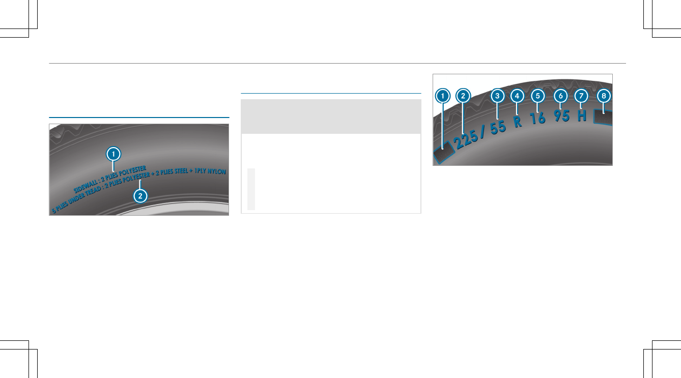
Tire size designation ............................438
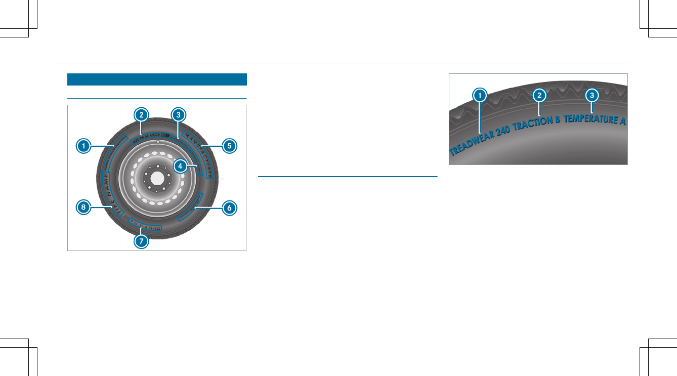
Traction grade .....................................435
Tread wear grade .................................435
Tire load (maximum) ...............................437
Tire pressure ................................... 425, 426
Checking (manually) ............................ 426
Checking (tire pressure monitoring
system) ............................................... 428
Maximum ............................................ 437
Notes ................................................... 424
Restarting the tire pressure loss
warning system ................................... 430
Restarting the tire pressure monitor‐
ing system ...........................................429
Tire pressure loss warning system
(function) ............................................. 429
Tire pressure monitoring system
(function) ............................................. 427
Tire pressure table .............................. 425
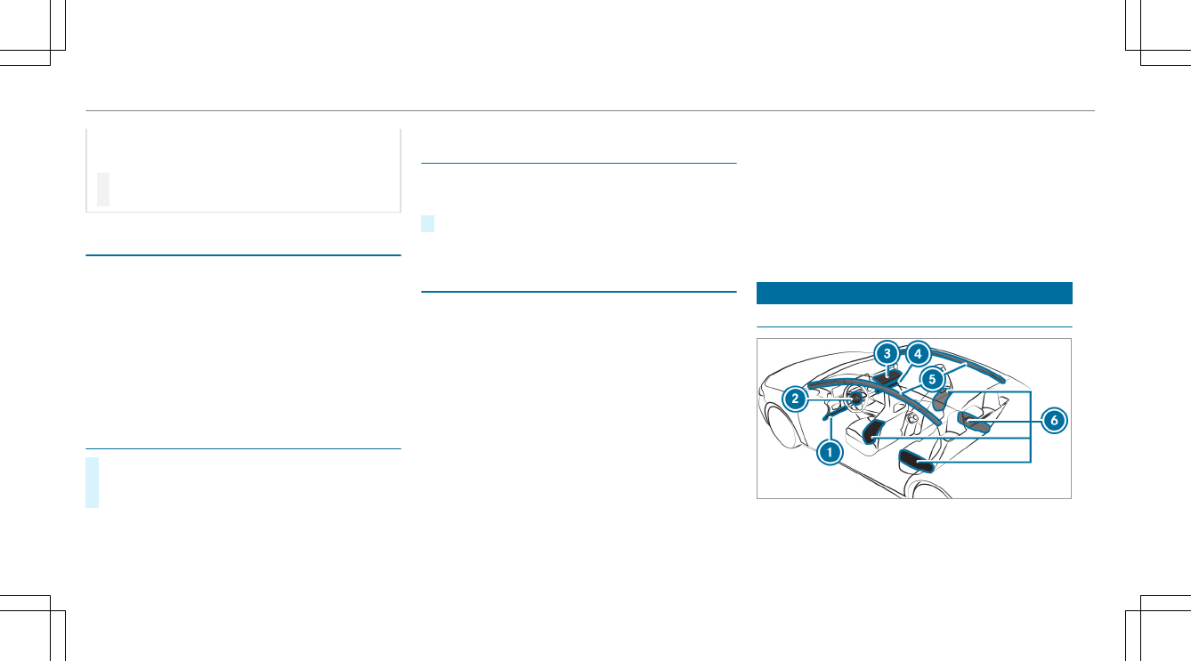
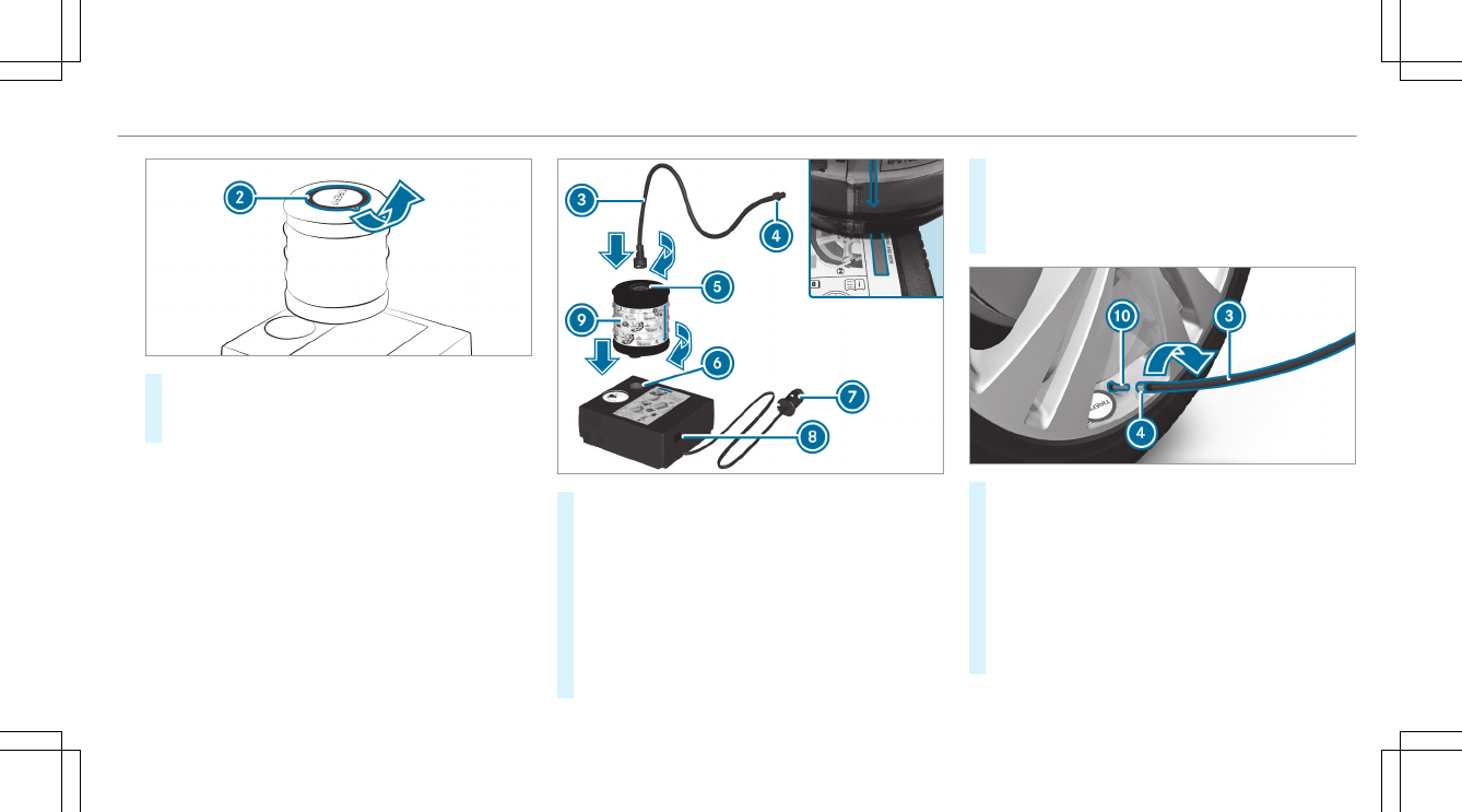
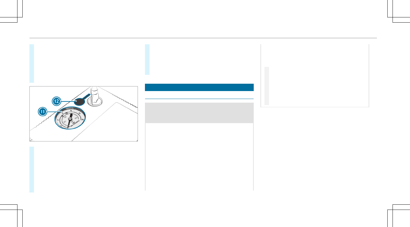
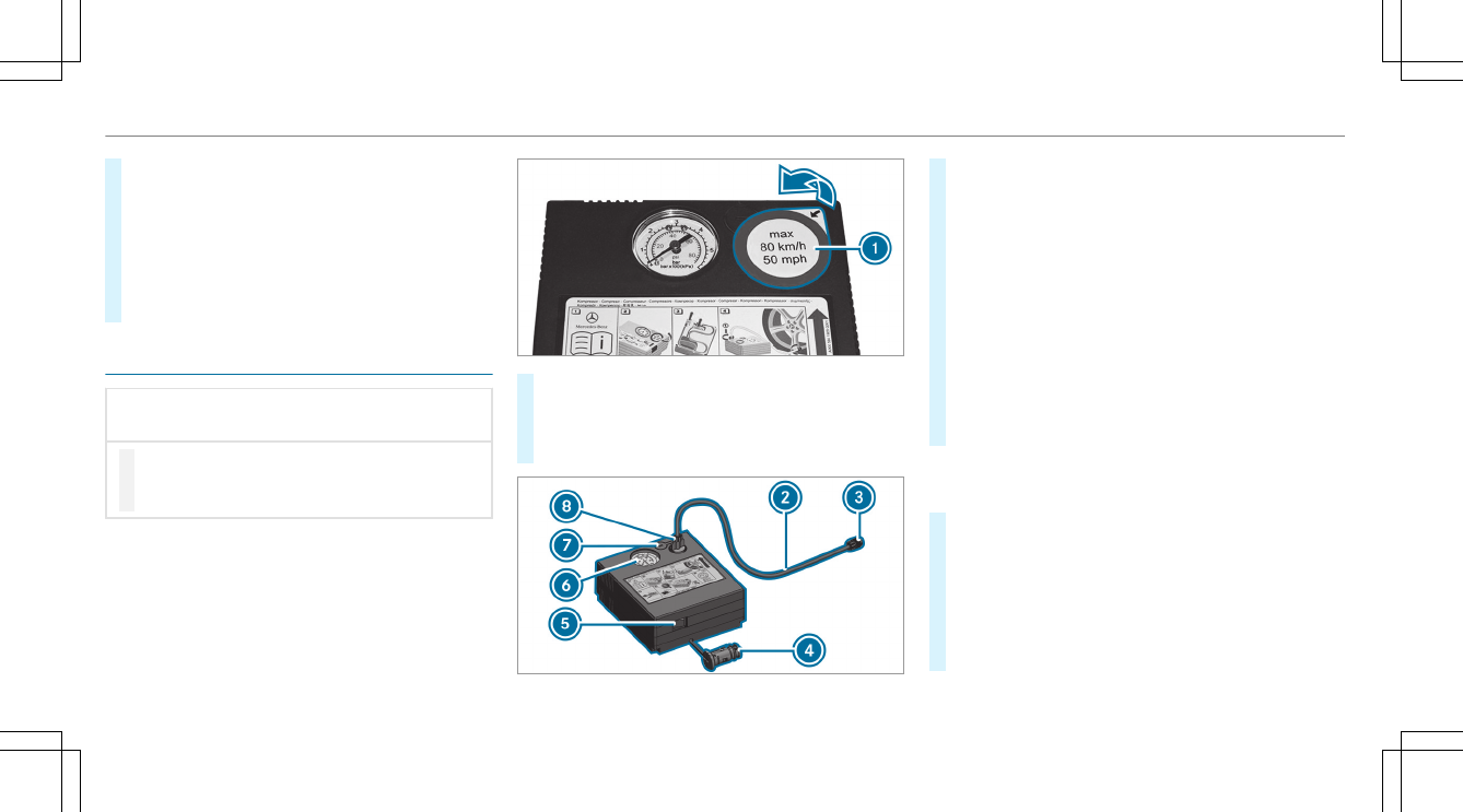
TIREFIT kit ...........................................403
Tire pressure loss warning system
Function .............................................. 429
Restarting ............................................ 430
Tire pressure monitor ............................. 429
Function .............................................. 427
Restarting ............................................ 429
Tire pressure monitoring system
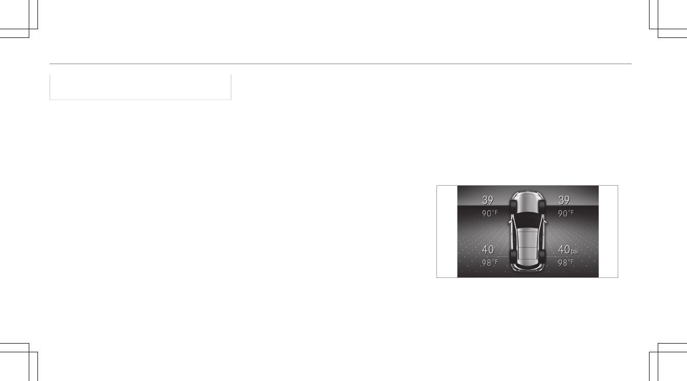
Checking the tire pressure .................. 428
Checking the tire temperature ............ 428
Tire pressure table .................................. 425
Tire Quality Grading ................................ 435
Tire temperature
Checking (tire pressure monitoring
system) ............................................... 428
Tire pressure monitoring system
(function) ............................................. 427
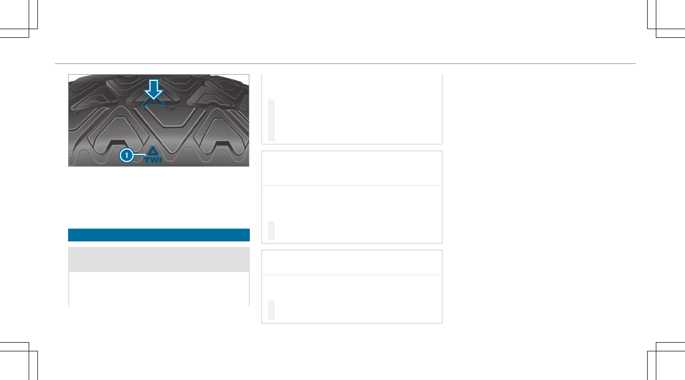
Tire tread ................................................. 422
Tire-change tool kit
Overview .............................................446
TIREFIT kit ................................................ 403
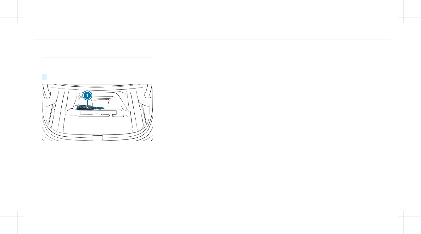
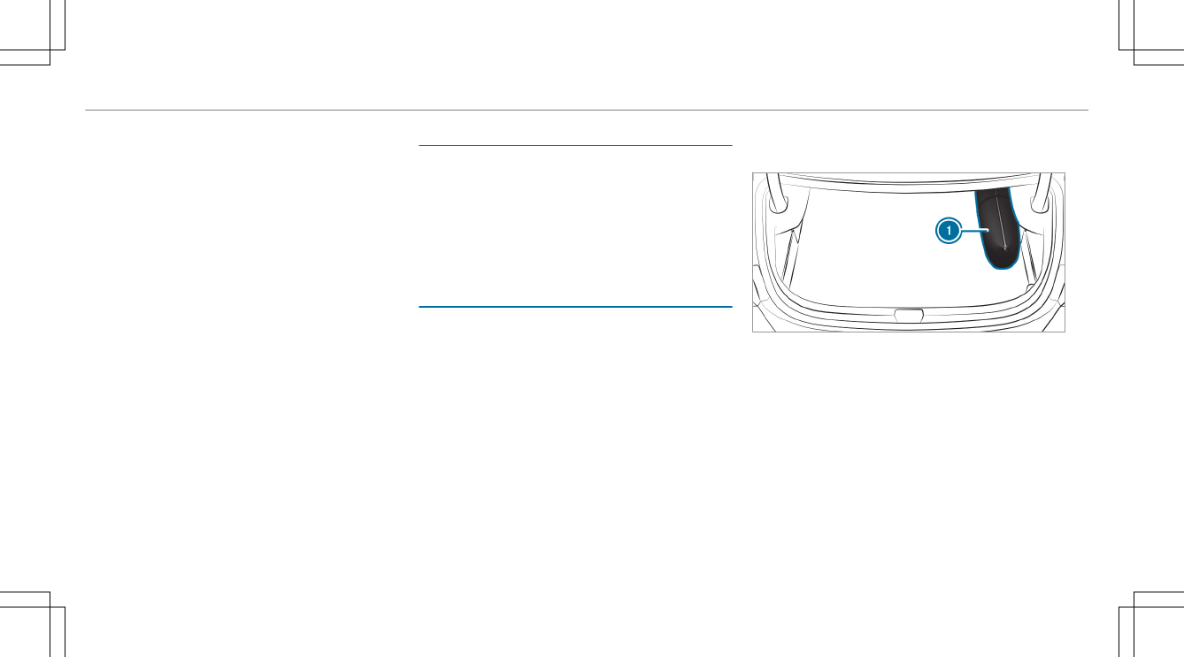
Storage location ..................................403
Using ................................................... 403
Tires
Changing hub caps .............................. 447
Characteristics .................................... 438
Checking .............................................422
Checking the tire pressure (man‐
ually) ................................................... 426
Checking the tire pressure (tire pres‐
sure monitoring system) ......................428
Definitions ...........................................440
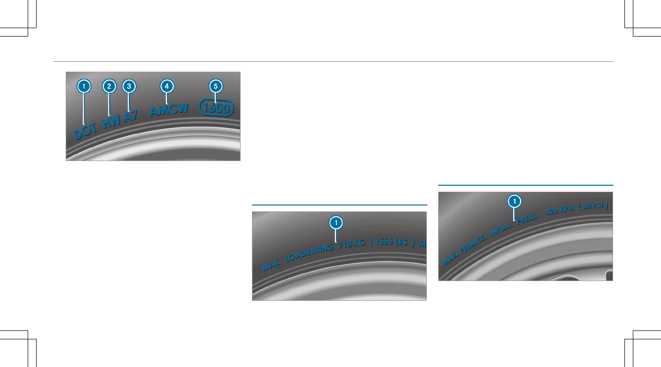
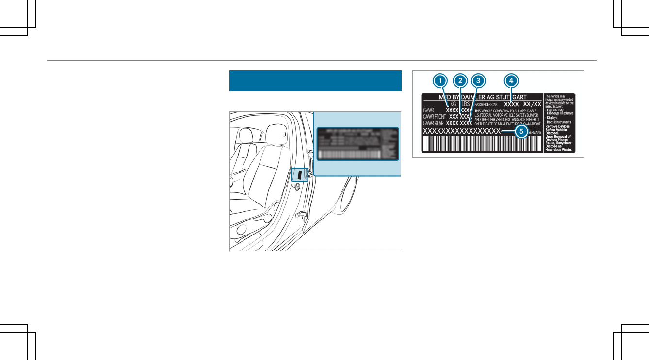
DOT, Tire Identification Number (TIN)
.............................................................436
Flat tire ................................................ 401
Installing .............................................. 450
Load index ...........................................438
Load-bearing capacity .........................438
Maximum tire load ............................... 437
Maximum tire pressure ....................... 437
MOExtended tires ................................ 402
Noise ................................................... 422
Notes on installing .............................. 443
Overview of tire labeling ......................435
Removing ............................................ 450
Replacing .................................... 443, 447
Restarting the tire pressure loss
warning system ................................... 430
Restarting the tire pressure monitor‐
ing system ...........................................429
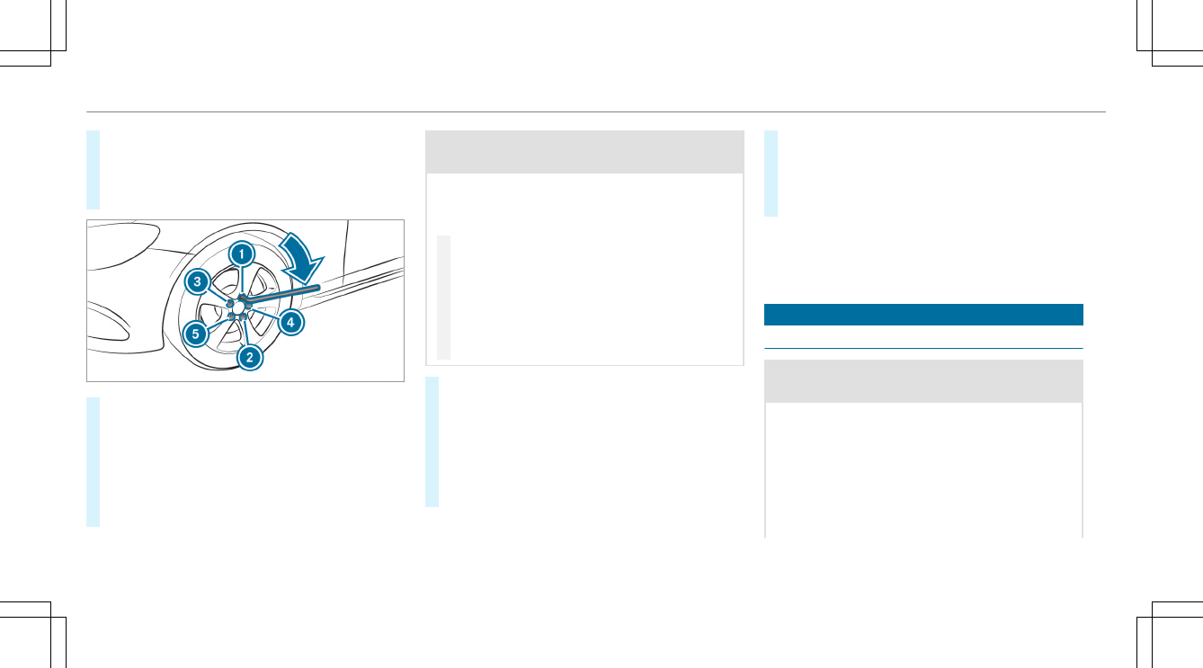
Rotating ............................................... 445
Selection ............................................. 443
Snow chains ........................................ 423
Index
561