If FAN is selected, room temperature isn't controlled,operation being continuously.If FAN is selected, room temperature isn't controlled,operation being continuously.
26 C~28 C
HEAT
22 C~24 C
COOL
DRY
21 C~24 C
NOTE
Press the FAN SPEED button.
Set to your favorite air flow rate.Set to your favorite air flow rate.
To Stop:
Press the ON/OFF button.
Air is not blown out at during operation.Air is not blown out at during operation.
Changing procedure of the content of the operation
Set to the new content.Set to the new content.
The content of the operation can be set or changed
even while the air conditioner is off operation.
The content of the operation can be set or changed
even while the air conditioner is off operation.
2
1
4
3
When cells are inserted,the present time is automatically set to AM12:00When cells are inserted,the present time is automatically set to AM12:00
Ex:Set to AM10:30.Ex:Set to AM10:30.
1
Please slide and remove the cover.
Press the CLOCK switch,with the tip of a ball pen, etc,
the present time can be set.
3
NOTE
The timer is set on the basis of the present time.So set the
present time correctly.
The timer is set on the basis of the present time.So set the
present time correctly.
1,4
2
Press the HR button to set the HR.
Press the HRbutton to set the MIN.
Press the clock switch to confirm.
ON/OFF
CLOCK
RESET
HR.
MIN.
Present time setting procedure
7
Specification of
Liquid pipe
12.7
9.52
6.35
Max. length
20m
15m
25m
Additional refrigerant
(L-5)X0.05 kg
(L-5)X0.03 kg
(L-5)X0.10 kg
The additional refrigerant should be charged from the service port of the 3-way valve
when the appliance is operating in cooling mode.
Do not allow air enter the refrigeration system while charging refrigerant.
(* "L" refers to length of connection pipe.)
Open/Close the valves
Open/Close the spools or the valves of outdoor unit with a f5mm hexagon spanner.
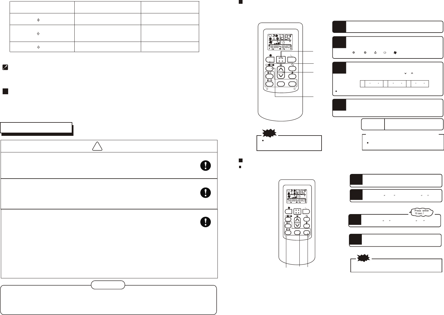
!
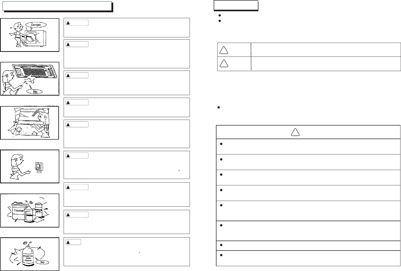
WARNING
Specified power cables should be used. Do not apply any pressure on the
terminals used to connect.
Grounding must be properly done.
Improper connection may cause fire.
Electric Wiring must be done by professionals. Use a separate circuit according
to national regulations.
The grounding wire should be away from gas pipes, water pipes, telephone,
lightening rods or other grounding wires. Improper grounding may cause electric
shock.
If the wiring capacity is not enough, electric shock or fire may occur.
If the supply cord is damaged, it must be replaced by the manufacturer or its service agent
or a similarly qualified person in order to avoid a hazard
An all-pole disconnection switch having a contact separation of at least 3mm in all poles sho-
uld beconnected in fixed wiring.
Be sure to Install Current Leakage Protection Switch. Or electric shock may occur.
the appliance must be positioned so that the plug is accessible
the appliance shall be installed in accordance with national wiring regulations
CAUTION
22
ELECTRIC WIRING
The temperature of refrigerant circuit will be hight ,please keep the interconnection
able away from the copper tube.
3
4
2
3
Air flow direction adjustment procedureThis type has no this function
Up/down direction can be adjusted by using the AIRFLOW button on the remote controller.
This button,each time pressed,changes the mode in the following sequence:
Up/down direction can be adjusted by using the AIRFLOW button on the remote controller.
This button,each time pressed,changes the mode in the following sequence:
Adjusting air flow direction
NOTE
When the room temperature controller(thermostat)trips in the heating mode or when the defrosting operation is conducted,the blow flap changes automatically to theWhen the room temperature controller(thermostat)trips in the heating mode or when the defrosting operation is conducted,the blow flap changes automatically to the
horizontal position.horizontal position.
When the heating operation has just started and the room temperature is still low,it may take a little time before the flap moves to the above sway operation angle.When the heating operation has just started and the room temperature is still low,it may take a little time before the flap moves to the above sway operation angle.
The flap may stop at the tilted down-blow position during the"Sway operation"in the heating mode,The flap may stop at the tilted down-blow position during the"Sway operation"in the heating mode,
AUTO
push the LOUVER button,changes the mode to swing louver.
Push the button,to stop swing.
push the LOUVER button,changes the mode to swing louver.
Push the button,to stop swing.
About TIMER operation
About Amenity reservation
Amenity reservation funcition is provided to start the operation a little earlierAmenity reservation funcition is provided to start the operation a little earlier
so that the room temperature is near the optimum temperature at the timer ONso that the room temperature is near the optimum temperature at the timer ON
time in case of starting the operation by TIMER ON/OFF.time in case of starting the operation by TIMER ON/OFF.
MechanismMechanism
Checking of the room temperatureChecking of the room temperature
starts 60 minutes ahead of the timerstarts 60 minutes ahead of the timer
ON time.Depeding on the tempera-ON time.Depeding on the tempera-
ture at that time,operation starts 5 to ture at that time,operation starts 5 to
60 minutes ahead of the timer ON time.60 minutes ahead of the timer ON time.
Amenity reseration is the functionAmenity reseration is the function
only for COOLand HEAT operationonly for COOLand HEAT operation
mode(including AUTO).It does notmode(including AUTO).It does not
actuate in DRY mode.actuate in DRY mode.
About SLEEP OperationAbout SLEEP Operation
When the SLEEP operation is selected,the room temperature is auto-
matically controlled with elapsed time so that the room isn't too cool
during cooling or too warm during heating.
During cooling and dry:Present temperature is raised 1 in an hour
(when the timer is set),and 2 raise in two hours.Then the temperature
dosen't change ever.
During heating:Present temperature is lowered 1 in an hour (when the
timer is set),and 2 lower in two hours.Then the temperature dosen't
change ever.
In cool operation In cool operation
Set
Temperature
Set
Temperature
Check the room
temp. 60 min
ahead
Check the room
temp. 60 min
ahead
Set timeSet time
(Operation)(Operation)
(Stop) Operation starts(Stop) Operation starts
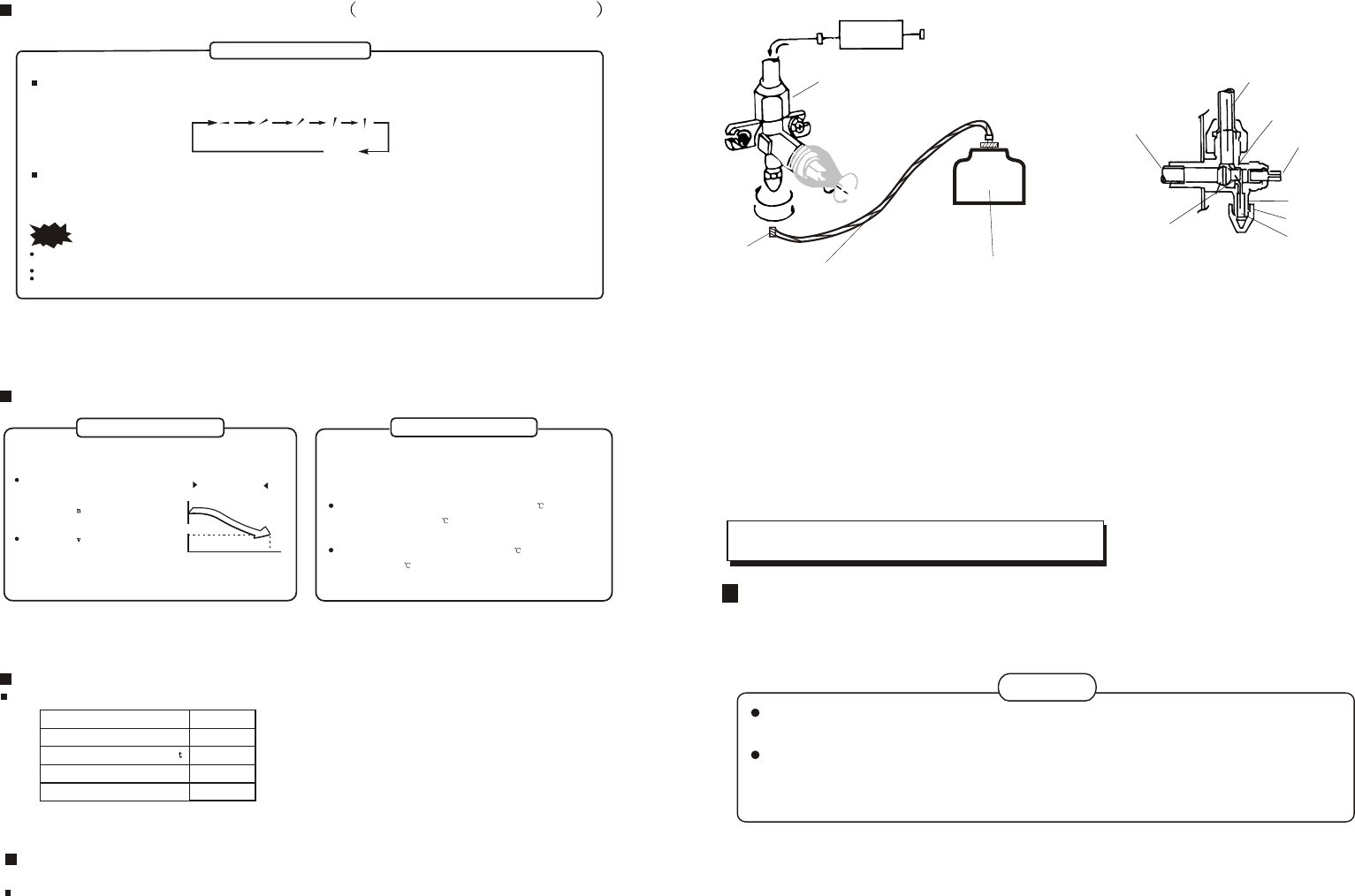
8
indoor unit
refrigerantflow direction
3-way valve
(6). If the uint has no leakage,then Tighten the
exhaust nut of 3-way valve.
(8)Back the exhaust nut to the uint..
(3).Loose the outlet nut of the additional freon refrigerant pot .
(1).Loosen the liquid pipe flare nut and remove the
exhaust nut of 3-way valve.
(2). Connect the outlet nut of the additional freon refrigerant
pot to the exhaust mouth .
(9).Loosen the valve spindle and core to Maximum.
(7).Press the spindle and let the additional freon
refrigerant leak out until the velocity of purging Air
is slow and warm .
3-way valve diagram
Connect to indoor unit
Close position
Valve spindle
Exhaust nut
Valve core
Connect to outdoor unit
Air exhaust process:
Connect hose
additional freon refrigerant pot
outlet nut
Refrigerant Volume to Be Added
Refrigerant volume to be added is calculated according to outdoor unit installation manual.
Be sure to add refrigerant measuring by a scale.
If the added refrigerant volume is inadequate (too much or insufficient), the compressor
malfunction will be caused. Be sure to calculate the refrigerant volume carefully.
The service man should write down the piping length and the added refrigerant volume
in the nameplate, which is on the electric control box cover of outdoor unit, for
diagnosing the compressor and refrigeration circulation malfunction.
CAUTION
The refrigerant refrigerant charge volume for the unit is based on using a 5m connecting
pipe. If the connecting pipe's length is longer than 5m, it is advisable to charge
additional refrigerant for the unit in order to achieve better operation.
21
Exhaust mouth
Exhaust spindle
(4).After exhausting air for almost one miniute,then
tighten the liquid pipe flare nut
Charge additional refrigerant
(5). Detect all the pipe joints leakage of freon in this
unit with soap water.
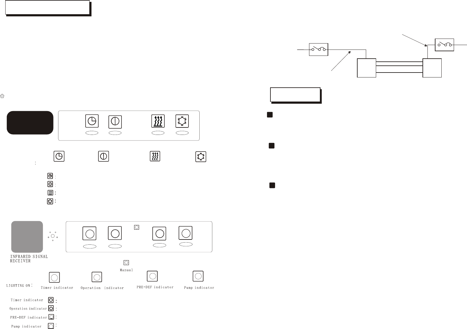
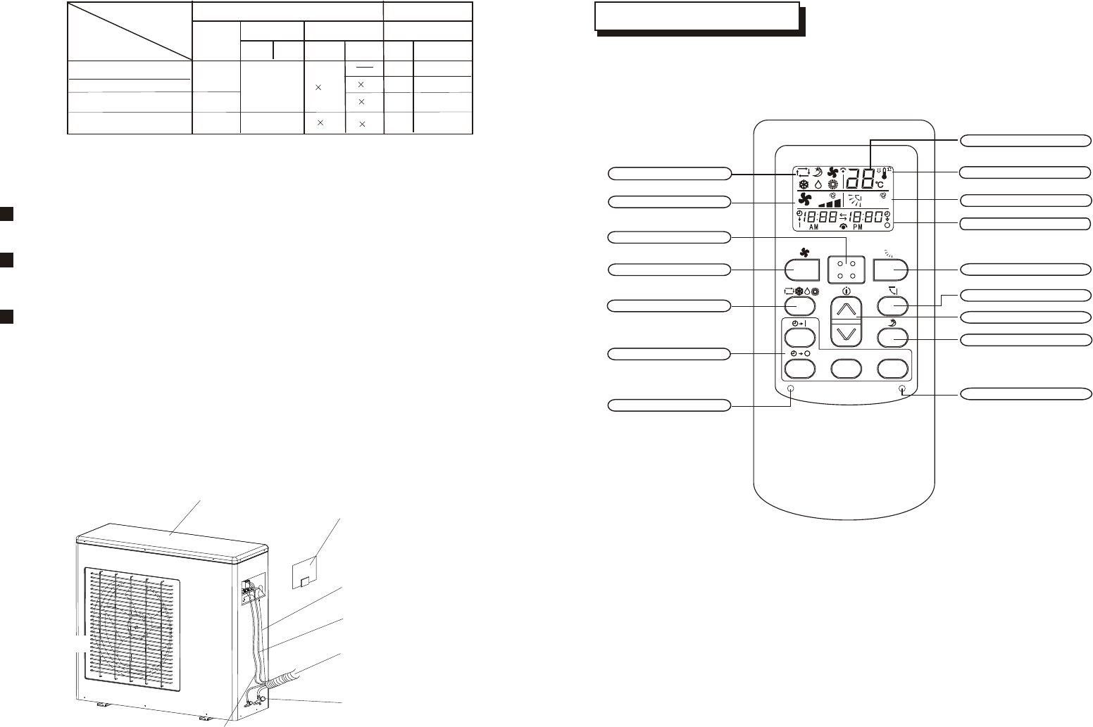
About FAN SPEED
Capacity of the air conditioner can be selected by your choice.During heating or cooling.Capacity of the air conditioner can be selected by your choice.During heating or cooling.
Operation capacity by your choice Operation capacity by your choice
Set automatically by microcomputer Set automatically by microcomputer
Powerful operation with high capaciy Powerful operation with high capaciy
Standard operation Standard operation
FAN SPEEDFAN SPEED
AUTOAUTO
HIHI
MEDMED
Energy-saving operation
Lo
About power-off memory function
When the air conditioner disconnect the power suddenly, restart it, the air conditioner operates at the mode
it did before power suddenly failed.
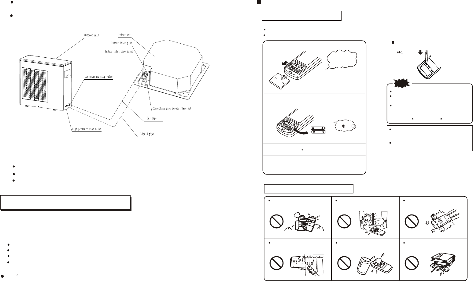
Remote controller handling procedure
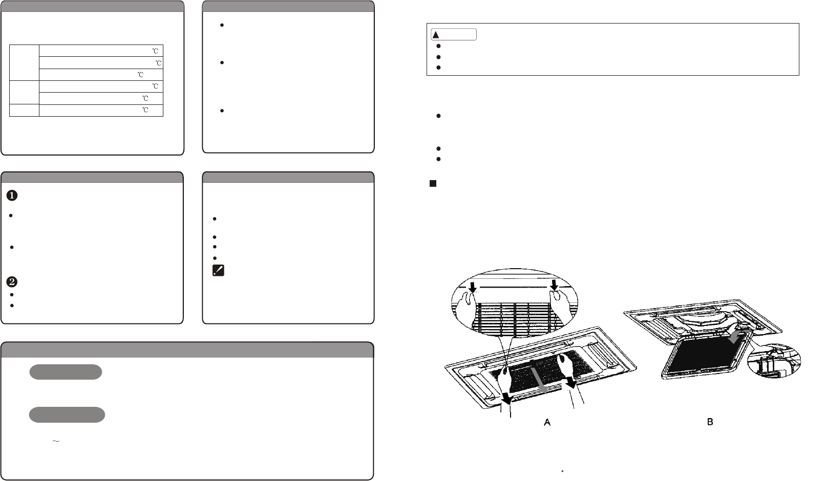
Batteries replacing procedure
Following cases signify dead cells.Replace the dead batteries with new ones.Following cases signify dead cells.Replace the dead batteries with new ones.
Receiving sound is not emitted from the unit when signal is transmitted.
Indicator becomes indistinct.
Receiving sound is not emitted from the unit when signal is transmitted.
Indicator becomes indistinct.
Please slide and remove the cover.Please slide and remove the cover.
Exchange the batteries.Exchange the batteries.
Install the cove.Install the cove.
Set it to the present time.Set it to the present time.
Guideline of the life time is printed on the battery.Guideline of the life time is printed on the battery.
The battery life may be shorter than that of the air The battery life may be shorter than that of the air
conditioner depending on the date of manufacture.conditioner depending on the date of manufacture.
However,the battery may be alive even after theHowever,the battery may be alive even after the
nominal life time expired.nominal life time expired.
When an abnormality appears in the display,When an abnormality appears in the display,
push the CLOCK button with a ball point pen,push the CLOCK button with a ball point pen,
NOTE
Do not use an old battery together with a new one.Do not use an old battery together with a new one.
Remove cells when the remote controller is notRemove cells when the remote controller is not
used for a long period.used for a long period.
The life of a cell made in conformity to JIS or IECThe life of a cell made in conformity to JIS or IEC
Is6to 12months in normal use.If it is used longer Is6to 12months in normal use.If it is used longer
or an unspecified cell is used,a liquid leaks fromor an unspecified cell is used,a liquid leaks from
the cell,cauing the remote cotroller inoperative.the cell,cauing the remote cotroller inoperative.
1
2
3
4
Attention to
the and
marks.
Attention to
the and
marks.
Slide the cover
upwardly in the
direction of the
arrow.
Slide the cover
upwardly in the
direction of the
arrow.
Note of remote controller handling
A place wlth high temperature such
as near an electric carpet or a stove.
A place unprotected from direct
sunlight or strong lighting.
It will be damaged if fallen.Be careful.
Do not put obstacles between the
remote controller and the unit.
Protect the remote controller from
being splashed with water,etc.
Do not put weights on the remote
controller.
9
Please refer to the following figures to install.
The following figure only shows the assembly relationship of the indoor unit ,outdoor
unit and refrigerant pipes.
NOTE
The throttle subassembly has been installed in the outdoor unit..
Use two spanners to connect the pipe with indoor/outdoor pipes to avoid the copper pipe cracking.
Please pay attention to the connection orientation when connecting.
Use a vacuum pump, to vacuum from the gas side refrigerant adding mouth of the outdoor
unit.
Dont use the refrigerant of the outdoor unit to do the vacuum. (A certain volume of refrigerant
had been added into the outdoor unit in factory.)
Air and moisture remains inside the refrigeration system, may has the following bad effects:
Rise of pressure inside the refrigeration system;
Decrease of cooling (or *heating) effect;
Moisture frozen and blocking the refrigeration system;
Rusting of certain parts of the system
After connecting the indoor and outdoor units , it is necessary to exhaust the air inside the
pipes completely as follows:
20
Air Purging
1.Location in the following places may cause malfunction of the machine. (If unavoidable,
please consult your local dealer)
a. A place where there is flammable gas leakage.
b. There is salty air surrounding(near the coast).
c. There is caustic gas(the sulfide, for example) existing in the air (near a hot spring).
d. A place where can not bear the weight of the machine.
e. In kitchen where it is full of oil gas
f. There is strong electromagnetic wave existing.
g. There is acid or alkaline liquid evaporating.
h. A place where air circulation is not enough.
I.The appliance shall not be installed in the laundry
2. Electrical Insulation must be done on the air conditioner and the building complying to
National Regulations.
CAUTIONS
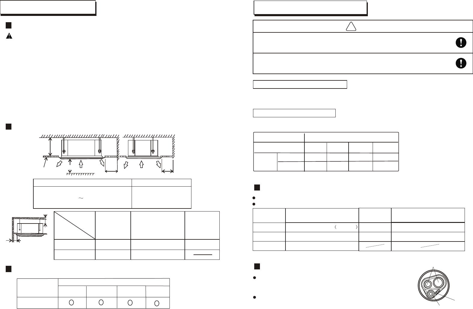
INSTALLATION LOCATIONS
HEIGHT BETWEEN CEILING AND FLOOR
INSTALLATION SPACE
Size A(mm) Ceiling Height
Above 330mm
Models
B
C
Wall
material
Up(B)
Sides(C)
Above 5cmAbove 5cmAbove 5cm
Above 100cmAbove 100cm
Flammable
material
Fire-proof
structure
Fire-proof material
or other nonflammable
materials other than
metal
A
Ceiling
Above 250cm
Above
100cm
Above
100cm
Obstacle
Model
2.7m<h<3.2m
Installation height
INDOOR UNIT INSTALLATION
The signal"o"refers that the model suits the corresponding installation height.
12000Btu/h,18000Btu/h
10
Leaked refrigerant will generate poisonous gas if meeting fire.
Allowed Length and Drop of Pipes
Material and Size of the Pipes
Requirements are different when installing the outdoor unit.
Three lengths (3m,5m,10m) of pipes are available to purchase.
f6.35(1/4inch)
Copper Pipe for Air ConditionerPipe Material
Size(mm)
Gas side
Liquid side
Pipe external
diameter
Added wrench torque
9.52
15.88
32.7(3.33kgf.m) ~
61.8(6.3kgf.m)~75.4(7.7kgf.m)
F
F
Connection of the Refrigerant Pipe
Double-span should be used when connecting the pipes.
The wrench torque follow the below table:
39.9(4.07kgf.m)
(N.m)
Wrap the connecting pipes and cables together with tape,
but not including the drainage pipe. Drainage pipe can be
fixed along them separately.
Wrapping from the joint of outdoor unit to that of indoor unit,
each round of tape should cover half of its previous one.
Wrap the piping
!
CAUTION
REFRIGERANT PIPE INSTALLATION
Ventilate the air if there was any refrigerant leakage during the installation.
Make sure there is no refrigerant leakage after the installation.
Leaked refrigerant will generate poisonous gas if meeting fire.
Pipe external
diameter
Added wrench torque
12.7
19.05
49.5(5.04kgf.m) ~
97.2(9.9kgf.m)~118.6(12.1kgf.m)
F
F
60.3(6.16kgf.m)
(N.m)
Connecting pipes
Cables
Drainage pipe
19
F6.35
14.2(1.4kgf.m)~17.01.7kgf.m
18000Btu/h42000Btu/h
24000Btu/h
Model
7K-12K14K-19K
23K-28K30K-48K
f9.52(3/8inch)
f6.35(1/4inch)
f12.7(1/2inch)
f15.8(5/8inch)
f9.52(3/8inch)
f12.7(1/2inch)
f19.05(3/4inch)
*7K-12K refers to the cooling capacity of duct type which is between 7000BTU/h and 12000BTU/h.
36000Btu/h
42000Btu/h,48000Btu/h
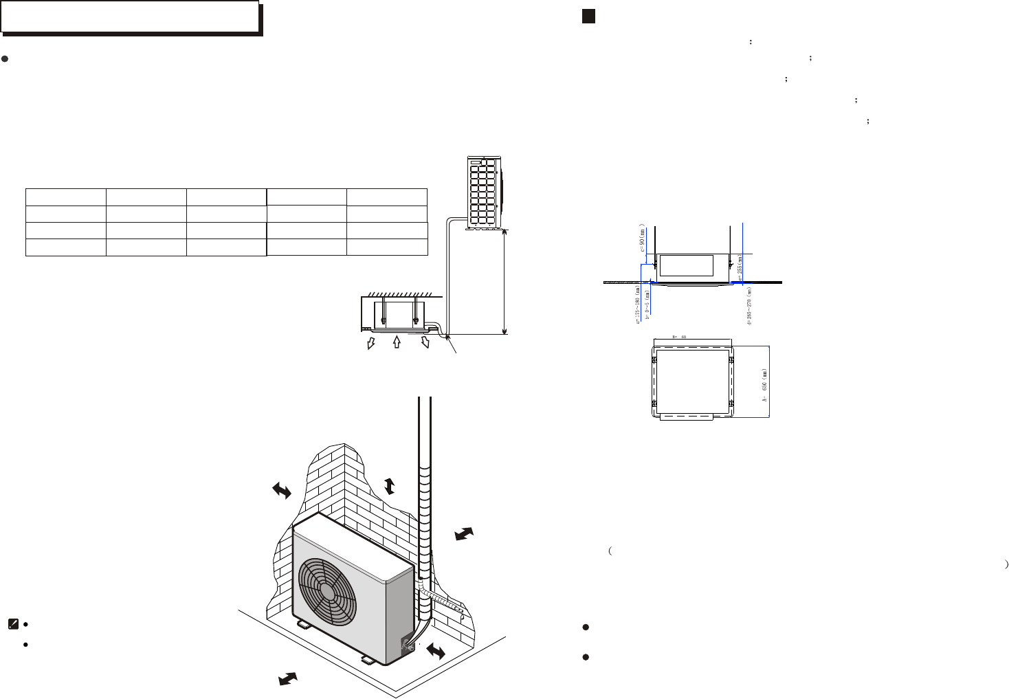
Location for installing outdoor unit
1. Install it at a place where it is convenient for installation and
well ventilated.
2. Keep the required distance away from the wall as reqiured on
the previous page when carrying on installation.
3. Pipe length and drop height should comply with the
scope required below.
4. When operating at a special place, for example, a place
of greasy dirt, vulcanization gas or high-salty seashore,
make sure to adopt an effective isolation measure.
5. Avoid installing it on the roadside where there is a risk
of muddy water.
6. Install it where your neighbors would not be annoyed by
operating noise or discharged hot air.
7. Install it on a fixed shelf that is not subject to increasing noise.
8. Install it at a place without blockage for air outlet.
Outdoor unit
Indoor
unit
elbow to
prevent water
from entering room
M
ax
dro
p
h
e
i
ght
L
15m
20m
25m
25m
9m
10m
10m
7.5m
5
5
5
OUTDOOR UNIT INSTALLATION
Please install the air conditioner
according to international rules.
Above figure is only a simple presentation of the unit,
it may not match the external appearance of the unit
you purchased.
Over
100mm
Over 1500mm
Over 200mm
Over 500mm
Over 100mm
Max pipe length
Max drop height L
Max. bending No.
5
Model
18
Select installation location considering piping and wiring connection after the Indoor Unit has
been hanged. Then decide the piping wiring leading direction.
Be sure to lead the refrigerant pipes, drain pipes and connection wires out to its connection
location before hanging the unit if the opening on the ceiling has been decided.
Confirm sizes of the indoor unit and ceiling opening with the attached installation paper
pattern. (Please fix the paper pattern below the body with M5X16 screws (4).
INDOOR UNIT INSTALLATION
11
INSTALLATION DIMENSION
18000Btu/h
SHAPE OF INDOOR UINT
a. hook and ceilingdistance between
b.height of panel ceiling sponge
c.distance between hook and indoor unit top
d.distance between ceiling and indoor unit top
e.height of indoor unit;
A.dimension of panel
Please select the space to install indoor uint according to the dimension show
above,then install correctly,and have enough space for maintenance.
36000Btu/h
42000Btu/h
48000Btu/h
INSTALLATION DIMENSION
B.dimension of ceiling cut-out
C.dimension of indoor uint.
Hanging screw bolt
Hanging bolts
Supporting
angle steel
Wooden construction
Put the square timber overthe roof beam,
then install the hanging screw bolts.
Timber over the beam
Roof beam
Hanging Screw
Ceiling
New Concrete Bricks
For finished concrete bricks
(Blade shape
insertion)
(Slide insertion)
Inlaying or embedding the screw bolts.
Install the hanging hook with expansible
bolt into the concrete deep to 45~50mm
to prevent loose.
Steel bar
Embedding screw bolt
(Pipe hanging and embedding
screw bolt)
Installthesupporting angle steel.
Steel roof beam structure
Overhanging the indoor unit
Adjust the gasket (down side) to 90mm over the ceiling.
Hanging Bolt
Nut (Up Side)
Gasket (Up Side)
Installing Ear
Nut (Down Side)
Down side of the ceiling
Gasket (Down Side)
90mm
Bolt
Bolt with M10 whorl is to be used. The center distance between the bolts is decided by the size of the
unit . Use the following method to install:
Installation method should be changed under the different construction structure. Please consult
the professional for the detailed information.
After opening a hole, the ceiling should be horizontal and strong to prevent vibration.
Cut the beams at the hole and remove them.
Reinforcing the beams that have been cut and the beams fixing the ceiling .
Preparation Work on the Ceiling
1
2
CEILING HOLE AND THE HOOK INSTALLATION
Installation of the hanging screw bolt
12
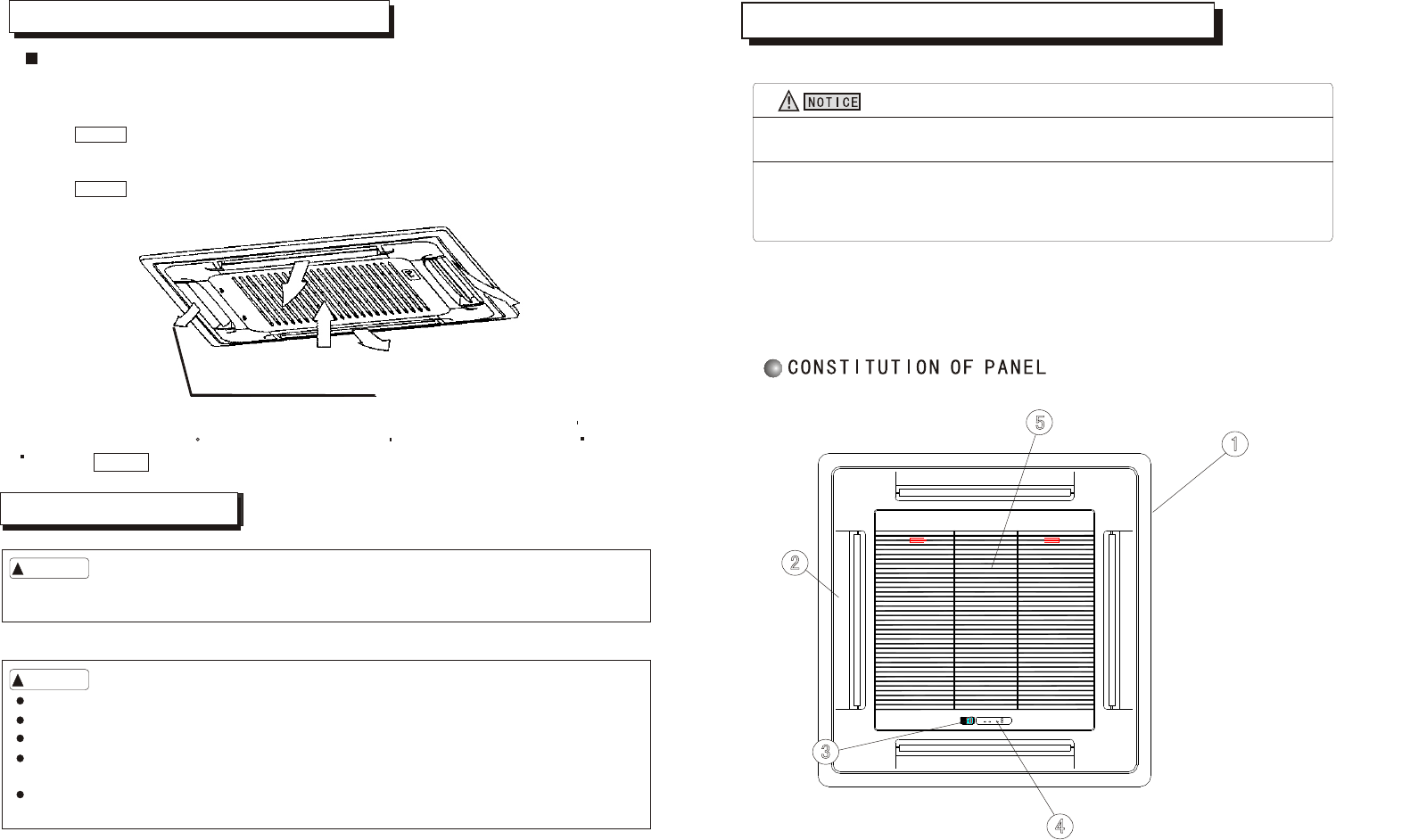
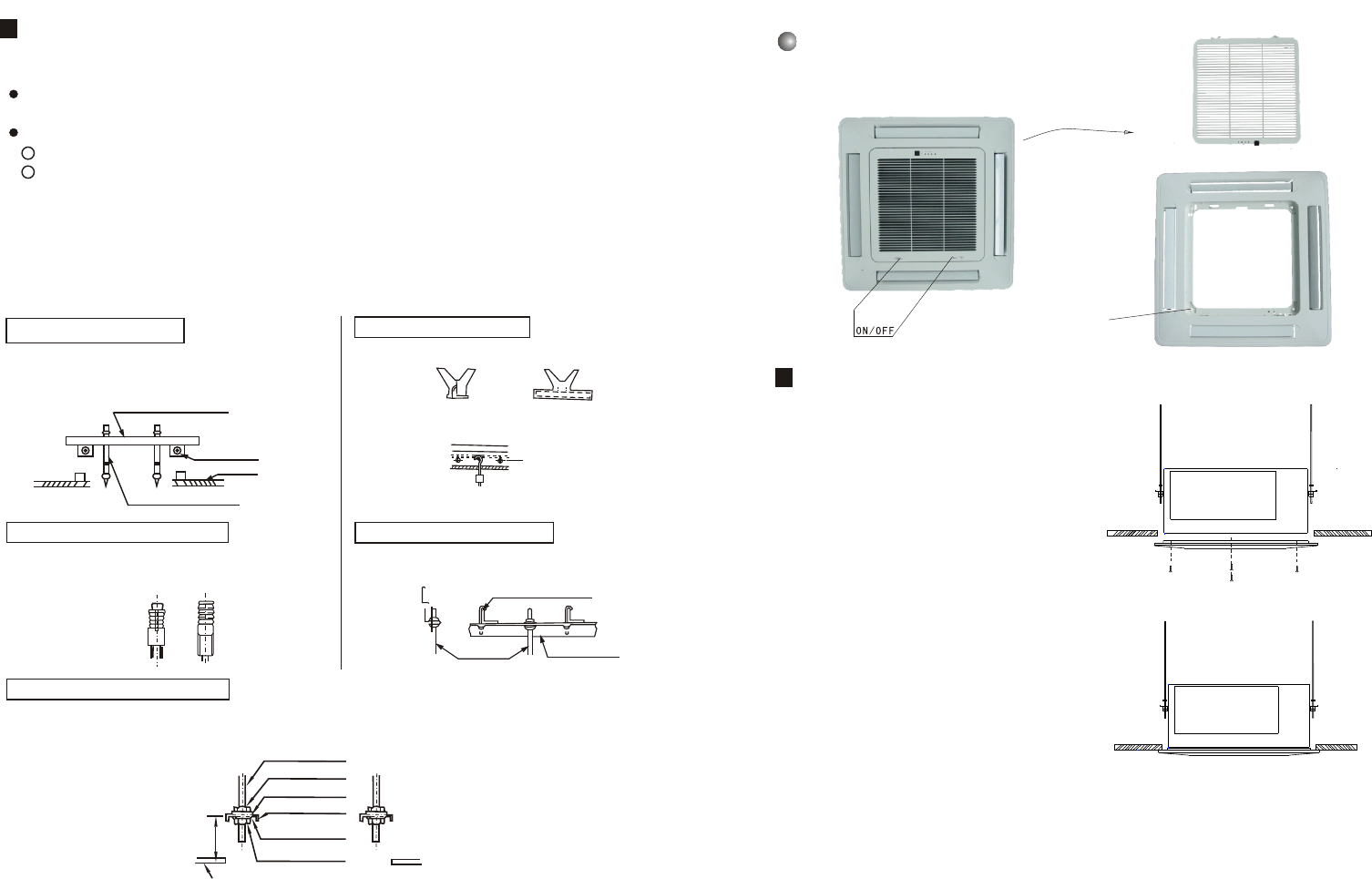
Unload air-in grille
Take off air-in grille
Installation bolt hole
INSTALLATION OF PANEL
1.Please screw M10 gasket and M6*20
bolt at the corner of indoor unit ,before
screwing them fasten ,screw other two
additional bolts which locates red bolt
showing as figure and notice that the
direction of red arrow on the electrical
box aligns the one on the panel.
2.Please connect step motor wire,display
board wire to the electrical box according
to ELECTRIC WIRING DIAGRAM on the
electrical box.
3.Then screw the other two M6*20 bolt with
M10 gasket through the hole of panel into
outdoor unit.
4.Adjust the location and direction of panel
to tally louver of panel with outlet of
outdoor,screw all the bolts fasten to
make the panel and outdoor unit
pressed together.
5.Return the air-in grille and panel back
to the outdoor unit.
.
17
12000Btu/h UNIT
18000Btu/h UNIT
¾Å ³ö·çÃæ°åµÄ°²×°
¾Å³ö·çÃæ°åµÄ°²×°
INSTALLATION OF PANEL
Unload air-in grille
Take off air-in grille
Unload panel installation cap
INSTALLATION OF PANEL
1.Please screw M10 gasket and M6*20 bolt at the corner of indoor
unit ,before screwing them fasten ,screw
other two additional bolts which locates
red bolt showing as figure and notice
that the direction of red arrow on the
electrical box aligns the one on the
panel.
2.Please connect step motor wire,display
board wire to the electrical box according
to ELECTRIC WIRING DIAGRAM on the electrical box.
3.Then screw the other two M6*20 bolt with M10 gasket
through the hole of panel into outdoor unit
4.Adjust the location and direction of panel
to tally louver of panel with outlet of
outdoor,screw all the bolts fasten to
make the panel and outdoor unit
pressed together.
5.Return the air-in grille and panel back
to the outdoor unit.
.
16
Screw down the bolts
linkingthe cap and
panel(four)
24000Btu/h, 36000Btu/h
48000Btu/h
42000Btu/h,
The drain pipe of indoor unit must have the heat insulation , or it will condense dew, as well as the
connections of the indoor unit.
The declivity of the drain pipe downwards should be over 2/100, and no winding and bending.
The total length of the drain pipe when pulled out traversely shall not exceed 20m , when the
pipe is over long, a prop stand must be installed every 1.5 to 2m to prevent winding.
Refer to the following figures about the installation of the pipes.
Do not impose any pressure on the connection part of the drainage pipe.
PANEL INSTALLATION (SOLD SEPARATELY)
Panel installation should be done after piping and wiring.
Be sure that the indoor unit and ceiling hole installation size is right before installation.
Be sure to seal the connection parts between - and the panel - the
indoor unit ,or even small gaps may cause wind/water leakage or condensing water.
the panel the ceiling
Be sure to follow Installation Manual during drainage installation,
the drainage pipe must have the heat insulation to prevent condensing.
CAUTION
CAUTION
DRAINAGE PIPE INSTALLATION
!
CAUTION
Tighten nut M10
Install the hanging bolt into T groove of the hanging tool. Overhang the indoor unit and ensure
it is level using a level indicator.
Level Indicator
Hanging Screw Bolt
Hanging Screw Bolt M10
Install it down the
installing-ear
Locking Nut M10
Hanging Ear
f10 Gasket
Indoor Unit
Ceiling
Installation Plate
2
30mm
1
43mm
13
Drainage Pipe Material, Heat-insulating Material
Measure diameter of the hard pipe using cutting method, and adjust the joining angle.
Pull out the flexible hose, do not over deform than illustrated below.
Gebruikershandleiding.com neemt misbruik van zijn services uitermate serieus. U kunt hieronder aangeven waarom deze vraag ongepast is. Wij controleren de vraag en zonodig wordt deze verwijderd.
Product:
Spelregels forum
Om tot zinvolle vragen te komen hanteren wij de volgende spelregels:
lees eerst de handleiding door;
controleer of uw vraag al eerder door iemand anders is gesteld;
probeer uw vraag zo duidelijk mogelijk te stellen;
heeft u een probleem en al geprobeerd om dit op te lossen, vermeld dit erbij aub;
heeft u een oplossing gekregen van een bezoeker dan horen wij dat graag in dit forum;
wilt u een reactie geven op een vraag of antwoord, gebruik dan niet dit formulier maar klik op de knop 'reageer op deze vraag';
uw vraag wordt direct op de website gezet; vermijd daarom persoonlijke gegevens in te vullen;
Belangrijk! Als er een antwoord wordt gegeven op uw vraag, dan is het voor de gever van het antwoord nuttig om te weten als u er wel (of niet) mee geholpen bent! Wij vragen u dus ook te reageren op een antwoord.
Belangrijk! Antwoorden worden ook per e-mail naar abonnees gestuurd. Laat uw emailadres achter op deze site, zodat u op de hoogte blijft. U krijgt dan ook andere vragen en antwoorden te zien.
Abonneren
Abonneer u voor het ontvangen van emails voor uw Maxicool CTL50H4A bij:
nieuwe vragen en antwoorden
nieuwe handleidingen
U ontvangt een email met instructies om u voor één of beide opties in te schrijven.
Ontvang uw handleiding per email
Vul uw emailadres in en ontvang de handleiding van Maxicool CTL50H4A in de taal/talen: Engels als bijlage per email.
De handleiding is 2,92 mb groot.
U ontvangt de handleiding per email binnen enkele minuten. Als u geen email heeft ontvangen, dan heeft u waarschijnlijk een verkeerd emailadres ingevuld of is uw mailbox te vol. Daarnaast kan het zijn dat uw internetprovider een maximum heeft aan de grootte per email. Omdat hier een handleiding wordt meegestuurd, kan het voorkomen dat de email groter is dan toegestaan bij uw provider.
Stel vragen via chat aan uw handleiding
Stel uw vraag over deze PDF
Uw handleiding is per email verstuurd. Controleer uw email
Als u niet binnen een kwartier uw email met handleiding ontvangen heeft, kan het zijn dat u een verkeerd emailadres heeft ingevuld of dat uw emailprovider een maximum grootte per email heeft ingesteld die kleiner is dan de grootte van de handleiding.
Er is een email naar u verstuurd om uw inschrijving definitief te maken.
Controleer uw email en volg de aanwijzingen op om uw inschrijving definitief te maken
U heeft geen emailadres opgegeven
Als u de handleiding per email wilt ontvangen, vul dan een geldig emailadres in.
Uw vraag is op deze pagina toegevoegd
Wilt u een email ontvangen bij een antwoord en/of nieuwe vragen? Vul dan hier uw emailadres in.