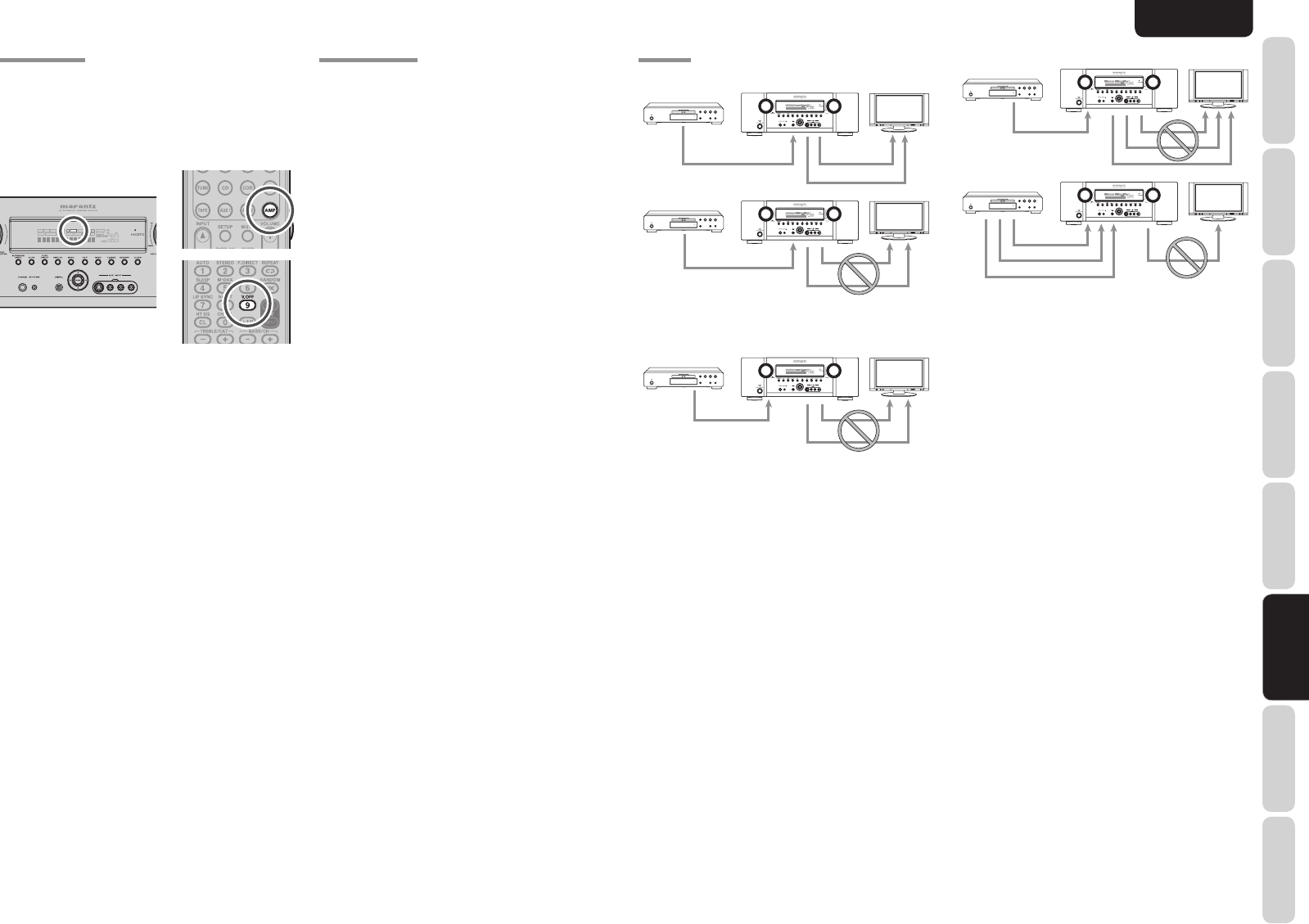
The connected monitor or projector does not support HDCP.• Connect to equipment that supports HDCP.
• Please change the method of connection.
The HDMI input of on the TV is not on.Set HDMI input so that it turns on, as explained in the TV’s instruction manual.
The HDMI output on the source component (DVD, Set Top Box,
etc.) is not on.
Set HDMI output so that it turns on, as explained in the source component’s instruction manual.
The HDMI mode is not correctly set on the unit.Set HDMI input on the FUNC INPUT SETUP menu as explained on page 15.
The HDMI output video resolution of the source component (DVD,
Set Top Box, etc.) does not match the TV specifi cations.
Set the resolution so that it matches, as explained in the instruction manuals of both components.
The device is connected with a non-standard HDMI cable.The 5 m or shorter cable is recommended to ensure stable operation and prevent image quality
deterioration.
Power to the unit is off. (When the unit is on standby, HDMI
connections cannot be turned on.)
Turn on the power to the unit.
The connection between HDMI components was not
authenticated.
Shut off and then turn the power back on to the unit, TV and source component.
The OSD menu does not appear
over an HDMI connection.
The unit SETUP menu does not support HDMI output.Use the COMPONENT VIDEO, S-VIDEO or VIDEO output.
Time is needed for the display of
an HDMI connection to appear.
The connection is being authenticated between the HDMI
devices.
There is nothing wrong with the system. Some HDMI devices require time for authentication.
Audio is not played back over an
HDMI connection.
The HDMI audio output of the source component (DVD, Set Top
Box, etc.) is not on.
Set the HDMI audio output so that it turns on, as explained in the source component’s instruction
manual.
The signal format of the source component (DVD, Set Top Box,
etc.) is not supported by the unit.
Set the HDMI audio output so that it can connect to the unit, as explained in the source component’s
instruction manual.
The unit is set to the HDMI audio “THROUGH” mode.In the “THROUGH” mode, sound is not produced from the unit. Set it to “ENABLE”. (see page 24)
DVD-Audio is not played back
over an HDMI connection.
The DVD player does not support CPPM, therefore it cannot
output HDMI audio.
• Use a DVD-Audio player that supports CPPM.
• Turn on PCM downsampling on the DVD player.
• Use an analog connection.
Super Audio CD is not played
back over an HDMI connection.
The current HDMI connection does not support Super Audio
CDs.
Use an analog connection.
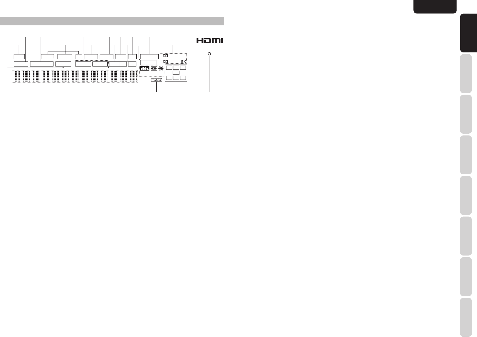
DISPMULTIAUTOTUNEDSTV
–
OFFNIGHTPEAKANALOG
DIGITAL
ATT
SLEEP
SURR
AUTO
DIRECTDISC 6.1MTX 6.1SPKRBEQ
DIGITAL
SURROUND
AAC
PCM
L
C
R
SLSSR
LFE
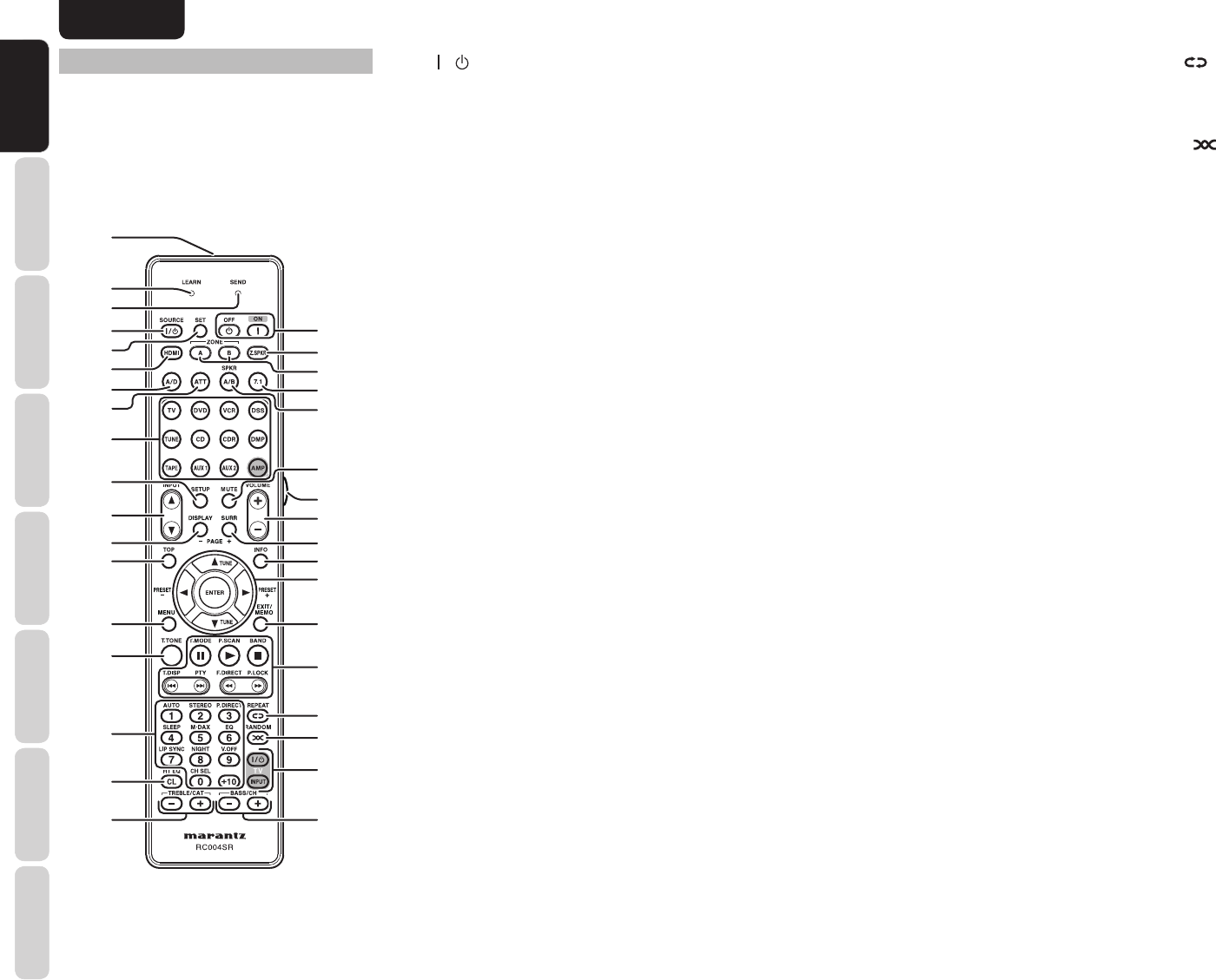
SURROUND MODEPURE DIRECTEXITCLEAR
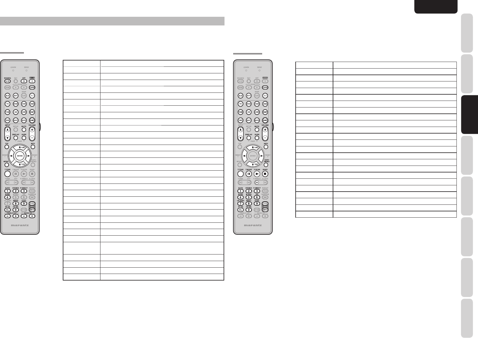
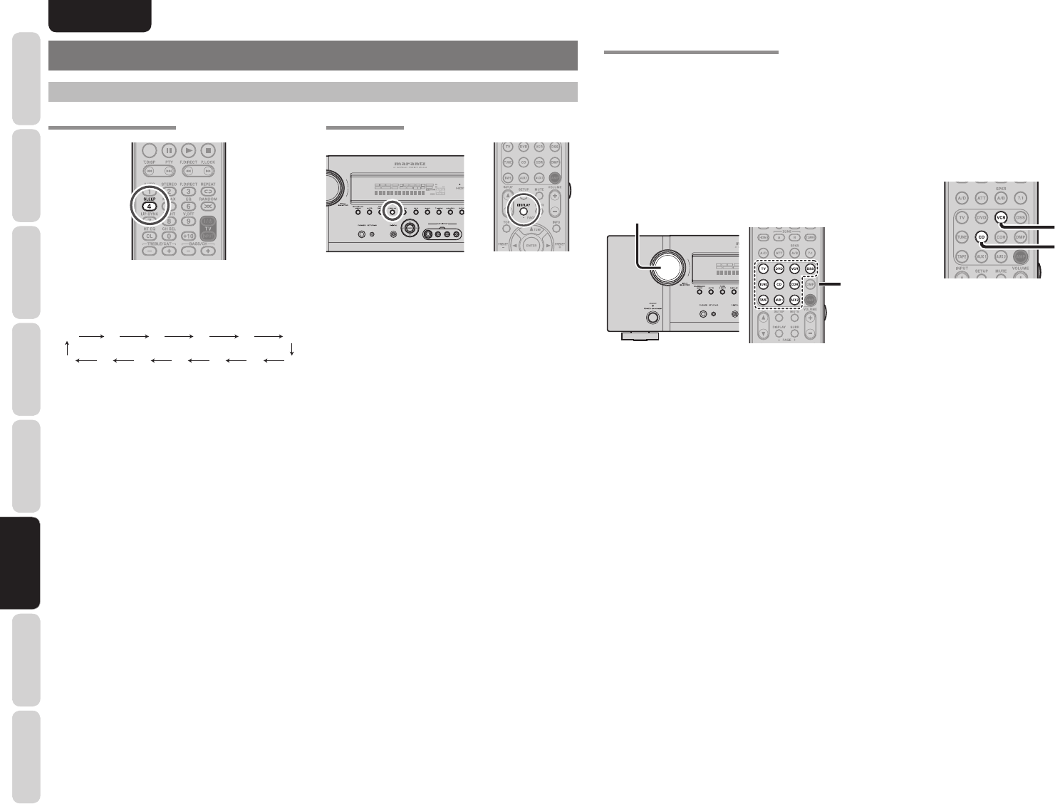
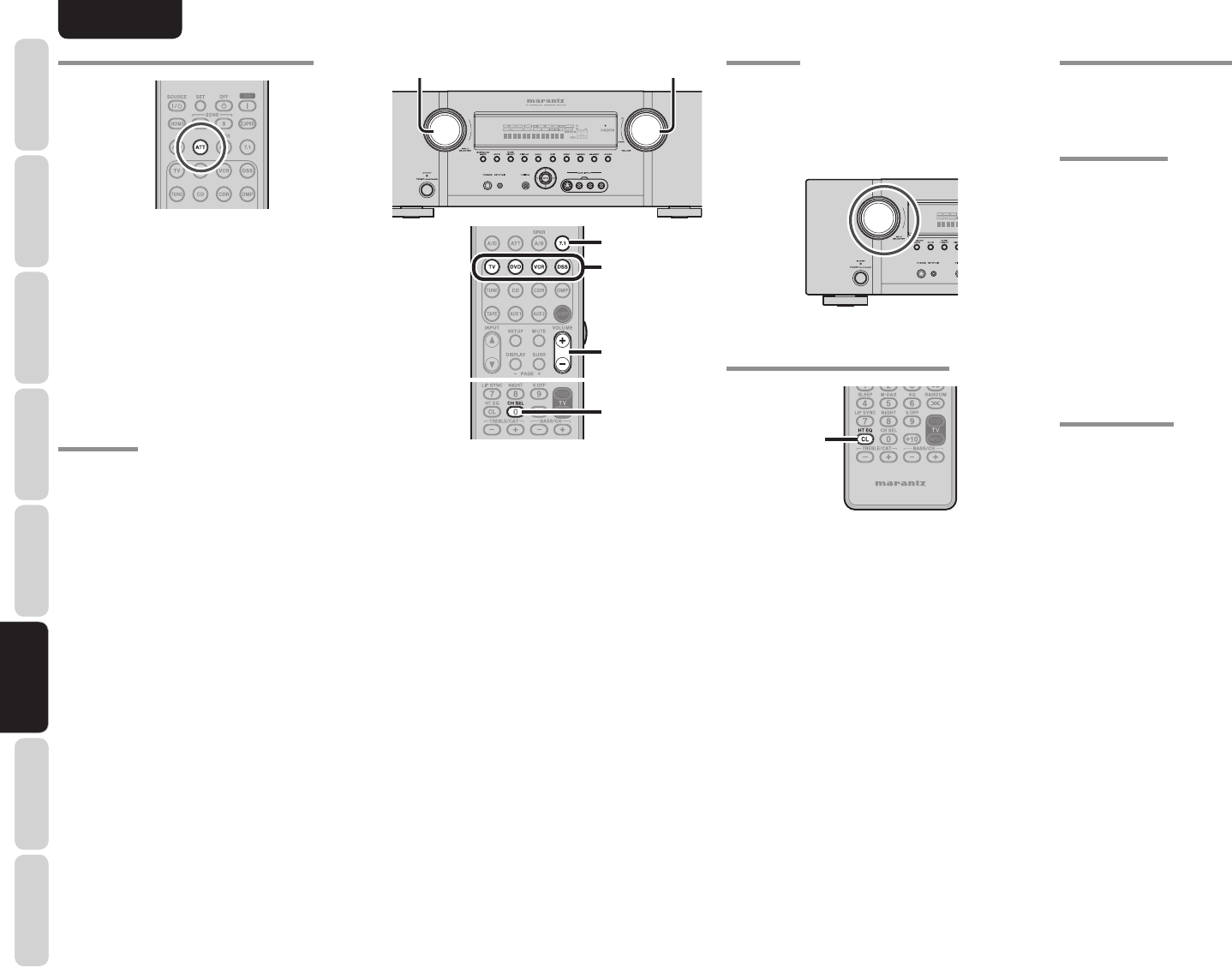
FRONT KEY (BUTTON) LOCK OF THE UNIT
If the PURE DIRECT and EXT buttons on the front
panel are both pressed at the same time for three
seconds or more, all the buttons on the front panel,
(excluding the POWER ON/OFF button), as well as
the INPUT SELECTOR knob and VOLUME knob,
will become locked. “F-KEY LOCK!” will appear in
the display.
Release the lock by pressing the same two keys
again at the same time for three seconds or more.
“F-KEY UNLOCK” will appear in the display, and the
keys will unlock.
GENERAL MALFUNCTION
If the equipment malfunctions, this may be because
an electrostatic discharge or AC line interference has
corrupted the information in the equipment memory
circuits. Therefore:
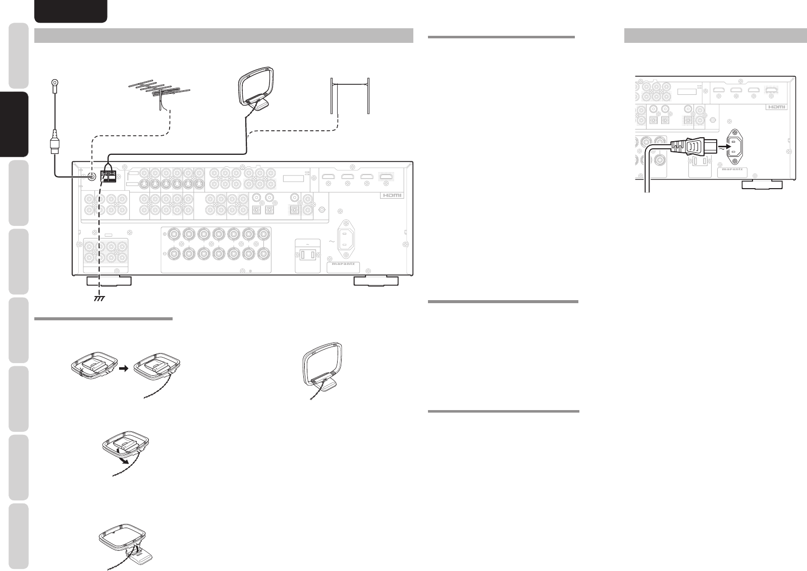
- disconnect the plug from the AC line supply
- after waiting at least three minutes, reconnect
the plug to the AC line supply
- re-attempt to operate the equipment
Memory backup
• In case a power outage occurs or the power
cord is accidentally unplugged, this unit is
equipped with a backup function to prevent
memory data such as the preset memory
from being erased.
HOW TO RESET THE UNIT
Should the operation or display seem to be abnormal,
reset the unit with the following procedure.
To turn on the unit, press and hold the SURROUND
MODE and CLEAR buttons simultaneously for 3
seconds or more.
Remember that the procedure will reset the settings
of the SOURCE, Surround mode, delay time, TUNER
PRESET etc., to their initial settings.
Note:
Sometimes, when “PROTECT” is shown on the unit’s display, the standby indicator fl ashes slowly (twice a second).
When this happens, turn off the unit’s power and remove the power cable. Then follow the procedure described below:
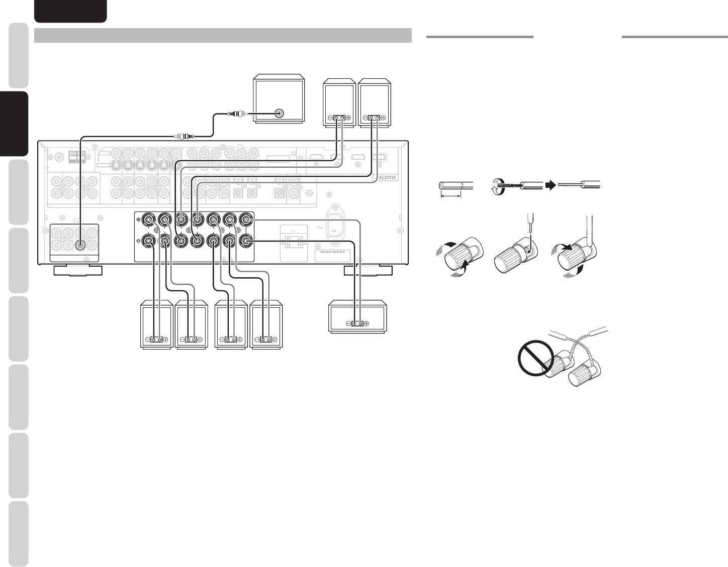
• Check to ensure that the speaker cables connected to the unit have not been connected with + and - connections reversed.
• Check to ensure that the speaker cables connected to the unit are not short-circuiting (check the connections both on the unit and on the speakers).
(Check that the playback volume is not greater than the unit can handle.)
• Check that the playback volume is not greater than the unit can handle.
After completing the above checks, connect the power cable and switch the unit back ON using the remote control.
Then, after reducing the volume, start playback and check that “PROTECT” is not appearing on the display and that there is no problem with speaker connections to the unit or
with sound reproduction.
If the same problem re-occurs, please contact your local service center to have it repaired.
On rare occasions, the unit will go into standby mode with the standby indicator fl ashing rapidly (eight times a second).
When this happens, it means that some major problem has occurred with the unit.
Quickly disconnect the power cable and take the unit to your local service center to have it repaired.
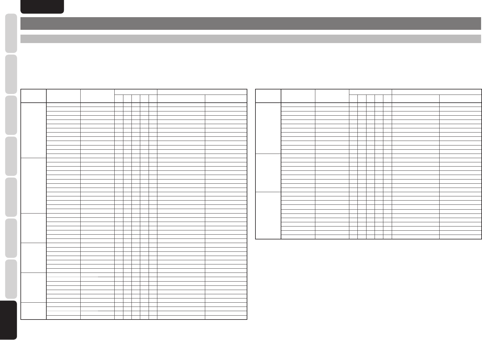
Multi Ch-PCMMulti Ch-PCMOOO-OPCML, C, R, SL, SR, LFE
Multi Ch-PCM 96kHzMulti Ch-PCM 96kHzOOO-OPCML, C, R, SL, SR, LFE
PCM (Audio)Multi Channel StereoOOOOO*PCML, R
AnalogMulti Channel StereoOOOOO*ANALOG-
OTHERS
SURROUND MODE
This unit is equipped with many surround modes. These are provided to reproduce a variety of surround sound effects, according to the content of the source to be played.
The available surround modes may be restricted depending on the input signal and speaker setup.
The relation between the selected surround mode and the input signal
The surround mode is selected with the surround mode selector on this unit or the remote controller. However, the sound you hear is subject to the relationship between the selected surround mode and input signal. That
relationship is as follows;
* : Depending on the particular setup, there may be differences compared to the information contained in
Gebruikershandleiding.com neemt misbruik van zijn services uitermate serieus. U kunt hieronder aangeven waarom deze vraag ongepast is. Wij controleren de vraag en zonodig wordt deze verwijderd.
Product:
Spelregels forum
Om tot zinvolle vragen te komen hanteren wij de volgende spelregels:
lees eerst de handleiding door;
controleer of uw vraag al eerder door iemand anders is gesteld;
probeer uw vraag zo duidelijk mogelijk te stellen;
heeft u een probleem en al geprobeerd om dit op te lossen, vermeld dit erbij aub;
heeft u een oplossing gekregen van een bezoeker dan horen wij dat graag in dit forum;
wilt u een reactie geven op een vraag of antwoord, gebruik dan niet dit formulier maar klik op de knop 'reageer op deze vraag';
uw vraag wordt direct op de website gezet; vermijd daarom persoonlijke gegevens in te vullen;
Belangrijk! Als er een antwoord wordt gegeven op uw vraag, dan is het voor de gever van het antwoord nuttig om te weten als u er wel (of niet) mee geholpen bent! Wij vragen u dus ook te reageren op een antwoord.
Belangrijk! Antwoorden worden ook per e-mail naar abonnees gestuurd. Laat uw emailadres achter op deze site, zodat u op de hoogte blijft. U krijgt dan ook andere vragen en antwoorden te zien.
Abonneren
Abonneer u voor het ontvangen van emails voor uw Marantz SR4003 bij:
nieuwe vragen en antwoorden
nieuwe handleidingen
U ontvangt een email met instructies om u voor één of beide opties in te schrijven.
Ontvang uw handleiding per email
Vul uw emailadres in en ontvang de handleiding van Marantz SR4003 in de taal/talen: Engels als bijlage per email.
De handleiding is 7,1 mb groot.
U ontvangt de handleiding per email binnen enkele minuten. Als u geen email heeft ontvangen, dan heeft u waarschijnlijk een verkeerd emailadres ingevuld of is uw mailbox te vol. Daarnaast kan het zijn dat uw internetprovider een maximum heeft aan de grootte per email. Omdat hier een handleiding wordt meegestuurd, kan het voorkomen dat de email groter is dan toegestaan bij uw provider.
Uw handleiding is per email verstuurd. Controleer uw email
Als u niet binnen een kwartier uw email met handleiding ontvangen heeft, kan het zijn dat u een verkeerd emailadres heeft ingevuld of dat uw emailprovider een maximum grootte per email heeft ingesteld die kleiner is dan de grootte van de handleiding.
Er is een email naar u verstuurd om uw inschrijving definitief te maken.
Controleer uw email en volg de aanwijzingen op om uw inschrijving definitief te maken
U heeft geen emailadres opgegeven
Als u de handleiding per email wilt ontvangen, vul dan een geldig emailadres in.
Uw vraag is op deze pagina toegevoegd
Wilt u een email ontvangen bij een antwoord en/of nieuwe vragen? Vul dan hier uw emailadres in.