Index ............................................................................................. 29
1
Thank you for purchasing this Marantz product.
To ensure proper operation, please read this owner’s manual
carefully before using the product.
After reading this manual, be sure to keep it for future
reference.
Accessories
Check that the following parts are supplied with the product.
.
Quick Start Guide
CD-ROM
(Owner’s Manual)
Safety Instructions
Cautions on Using Batteries
Power cord
Remote control unit
(RC005PMSA)
R03/AAA batteries
About the remote control
Inserting the batteries
1
Remove the rear lid in the direction of the
arrow and remove it.
.
2
Insert two batteries correctly into the battery
compartment as indicated.
.
Batteries
3
Put the rear cover back on.
NOTE
0
To prevent damage or leakage of battery fluid:
0
Do not use a new battery together with an old one.
0
Do not use two different types of batteries.
0
Remove the batteries from the remote control unit if it will
not be in use for long periods.
0
If the battery fluid should leak, carefully wipe the fluid off
the inside of the battery compartment and insert new
batteries.
Operating range of the remote
control unit
Point the remote control unit at the remote sensor when
operating it.
.
Approx. 7 m
30°
30°
ENGLISH
2
OverviewConnectionsPlaybackSettingsTipsAppendix
Features
High quality sound
0
HDAM
®
SA3 Module
The HDAM
®
SA3 is a key amplifier module for current
feedback amplifiers. It is installed in the voltage to current
converter, the most crucial component, to improve the
stability of the circuit and provide high-speed sound.
0
Linear Control Volume
The HDAM
®
SA3 is combined with a JRC volume IC to
achieve low distortion and high S/N. A range of volumes
between 0 and -99.5 dB can be smoothly controlled in ±0.5
dB steps.
0
Hypex Switching Power Amplifier Module
The power amplifier contains a Hypex NCore
®
switching
power amplifier module. This switching amplifier module
minimizes distortion from bass to treble and frequency
characteristics are not changed by the impedance of the
speakers, achieving extremely high performance. It can be
used with a high-speed pre-amplifier circuit containing the
HDAM
®
SA3 to faithfully and precisely convey the finely
detailed information in DSD and high-resolution sound
sources.
0
Marantz Musical Premium Phono EQ
The new Marantz Musical Premium Phono EQ phono
equalizer has been developed for MM/MC cartridges to
produce rich sound that is more similar to analog. This
circuit contains a new feedbackless equalizer amplifier and
MC head amplifier developed by HDAM. J-FET input is
used, enabling the input coupling condenser to be
eliminated. This improves the purity of the signal path in
the small signal section.
0
High Sound Quality Parts Employed
High sound quality parts are used in every part of the
circuit, including high sound quality MELF resistors and
film capacitors.
0
Double-layered chassis
0
High-grade copper machined analog audio input
connectors
(CD/PHONO only)
0
High-grade Machined Copper Speaker Terminals
High performance
0
F.C.B.S.
A Floating Control Bus System (F.C.B.S.) enables the user
to connect up to four PM-KI RUBY units, making a diversity
of applications possible with complete bi-amp and
multichannel connections. Moreover, a ground loop is not
formed among multiple PM-KI RUBY units connected;
therefore, sound quality is not adversely affected.
0
Bi-amp mode
Complete bi-amp connection proposed by Marantz
enables a level of reproduction of the acoustic field never
before achieved. Synchronized operation of two PM-KI
RUBY units is made possible by F.C.B.S. (Floating Control
Bus System) connection, with each PM-KI RUBY in Bi-
Amp mode working as a monaural integrated amplifier.
0
Power Amplifier Mode
In this mode, this unit works as a power amplifier.
0
Tone Control Amplifier
An electronic tone control amplifier is used to adjust the
bass and treble volumes in 1 dB steps within a ±6 dB
range.
ENGLISH
3
Part names and functions
Front panel
.
ioQ0
equytrww
A
INPUT SELECTOR knob
This selects the input source. (v p. 16)
B
Illumination lamp
The illumination lamp lights (blue).
C
Display
This displays various pieces of information.
D
Power indicator
This is lit as follows according to the power status:
0
Power on : Blue
0
Standby : Off
0
Power off : Off
E
STANDBY indicator
This is lit as follows according to the power status:
0
Power on : Off
0
Standby : Red
0
Power off : Off
F
TONE indicator
A blue lamp lights when tone control is turned
on. (v p. 17)
G
VOLUME knob
These adjust the volume level. (v
p. 16)
H
Headphones jack (PHONES)
Used to connect headphones.
When the headphones are plugged into this jack, audio
will no longer be output from the speaker terminals.
NOTE
0
To prevent hearing loss, do not raise the volume level
excessively when using headphones.
I
Power operation button (X)
This turns the power on/off. (v p. 16)
J
Remote control sensor
This receives signals from the remote control unit.
(v p. 2)
ENGLISH
4
OverviewConnectionsPlaybackSettingsTipsAppendix
Rear panel
.
AC IN
AC IN
AUDIO IN
AUDIO IN
POWER AMP IN
POWER AMP IN
AUDIO IN
AUDIO IN
CD
CD
LINE-1
LINE-1
PHONO
PHONO
SIGNAL
SIGNAL
GND
GND
LINE-2
LINE-2
RECORDER-
RECORDER-
1
RECORDER-
RECORDER-
2
RECORDER-
RECORDER-
1
RECORDER-
RECORDER-
2
SPEAKERS
SPEAKERS
IN
IN
ID
ID
STEREO
STEREO
BI-AMP
BI-AMP
F.C.B.S.
F.C.B.S.
REMOTE CONTROL
REMOTE CONTROL
AMP MODE
AMP MODE
OUT
OUT
IN
IN
OUT
OUT
AUDIO OUT
AUDIO OUT
ioQ
0
u
ertywq
A
Analog audio input connectors (AUDIO IN)
Connecting to a device with analog audio output
connectors.
0
“Connecting a playback device” (v p. 9)
0
“Connecting a recording device” (v p. 9)
B
Analog audio output connectors (AUDIO OUT)
Used to connect the input connector of a recorder.
(v
p. 9)
C
Power amplifier connectors (POWER AMP IN)
Used to connect a pre-amplifier when this unit is used as a
power amplifier. (v p. 14)
D
Speaker terminals (SPEAKERS)
Used to connect speakers. (v
p. 8)
E
Remote control input/output connectors (REMOTE
CONTROL)
Used to connect to a Marantz audio device that is
compatible with the remote control function. (v p. 15)
F
AMP MODE switch
Used to switch the amplifier mode (STEREO/BI-
AMP). (v p. 11)
G
SIGNAL GND terminal
Used to connect the ground wire of a turntable.
(v
p. 9)
H
F.C.B.S. connectors
Used to connect a high quality playback system using two
or more of PM-KI RUBY units. (v p. 10)
I
AC inlet (AC IN)
Used to connect the power cord. (v p. 15)
J
F.C.B.S. ID button
Used to set the ID number for F.C.B.S. (v p. 11)
ENGLISH
5
Remote control unit
The supplied remote control can be used to control a Marantz
CD player in addition to this unit.
0
“CD player operations” (v p. 7)
n
Operating this unit
To operate amplifier, press REMOTE MODE AMP button
to switch the remote control to the amplifier operation
mode.
.
t
r
e
w
u
y
i
o
Q1
Q2
Q0
q
A
Remote control signal transmitter
This transmits signals from the remote control unit.
(v p. 2)
B
Cursor buttons (uiop)
These select items.
C
DISPLAY button
Each press of this switches the brightness of the display.
Press and hold to turn the illumination lamp on/off.
D
Input source select buttons (INPUT df)
This selects the input source. (v
p. 16)
E
Power operation button (X AMP)
This turns the power on/off (standby).
(v p. 16)
F
Remote mode select button
(REMOTE MODE AMP)
This switches the remote control to amplifier control mode.
G
ENTER button
This determines the selection.
H
SETUP button
This displays the setting menu on the display.
(v
p. 19)
I
MODE/TRIM button
This displays the volume balance adjustment menu on the
display. (v
p. 17)
J
TONE button
Turns the tone control function on/off.
(v
p. 17)
K
VOLUME buttons (df)
These adjust the volume level. (v
p. 16)
L
MUTE button
This mutes the output audio. (v
p. 16)
ENGLISH
6
OverviewConnectionsPlaybackSettingsTipsAppendix
n
CD player operations
To operate a Marantz CD player, press the REMOTE
MODE CD button to switch the remote control to the CD
player operation mode.
.
q
w
e
r
t
u
i
o
Q0
Q1
y
Q7
Q9
Q8
Q3
Q5
Q6
Q2
Q4
A
Power operation button (X CD)
B
Remote mode select button (REMOTE MODE CD)
C
Cursor buttons (uiop)
D
DISPLAY button
E
System buttons
F
Information button (INFO)
G
Number buttons (0 – 9, +10)
H
RANDOM button
I
REPEAT button
J
FILTER button
K
SOUND MODE button
L
ENTER button
M
SETUP button
N
MODE/TRIM button
O
OPEN/CLOSE button
P
DISC/INPUT button
Q
CLEAR button
R
PROGRAM button
S
DIGITAL OUT button
0
Basic amplifier operations such as switching the input
source, trimming the volume and muting can be done even
when CD is set as the remote control operation mode.
0
When using it, also refer to the operating instructions of the
other devices.
0
The remote control may not operate some products.
ENGLISH
7
Connections
n
Contents
Connecting speakers8
Connecting a playback device9
Connecting a recording device9
Connecting multiple PM-KI RUBY units (F.C.B.S.
connection)10
Connecting a pre-amplifier14
Connecting devices with remote control connectors15
Connecting the power cord15
NOTE
0
Do not plug in the power cord until all connections have
been completed.
0
Do not bundle power cords together with connection
cables. Doing so can result in humming or noise.
n
Cables used for connections
Provide necessary cables according to the devices you
want to connect.
Speaker cable
.
Audio cable
.
R
L
R
L
Remote connector
cable
.
Connecting speakers
NOTE
0
Disconnect this unit’s power plug from the power outlet
before connecting the speakers.
0
Connect so that the speaker cable core wires do not
protrude from the speaker terminal. The protection circuit
may be activated if the core wires touch the rear panel or if
the + and - sides touch each other. (“Protection
circuit” (v p. 26))
0
Never touch the speaker terminals while the power cord is
connected. Doing so could result in electric shock.
0
Use speakers with an impedance of 4 – 16 Ω/ohms.
n
Connecting the speaker cables
Carefully check the left (L) and right (R) channels and + (red) and
- (white) polarities on the speakers being connected to this unit,
and be sure to connect the channels and polarities correctly.
1
Peel off about 10 mm of sheathing from the tip of
the speaker cable, then either twist the core wire
tightly or terminate it.
.
2
Turn the speaker terminal counterclockwise to
loosen it.
.
3
Insert the speaker cable’s core wire to the hilt
into the speaker terminal.
.
4
Turn the speaker terminal clockwise to tighten
it.
.
Spade lug connector
.
ENGLISH
8
OverviewConnectionsPlaybackSettingsTipsAppendix
Speaker connection
.
AC IN
AC IN
AUDIO IN
AUDIO IN
POWER AMP IN
POWER AMP IN
AUDIO IN
AUDIO IN
CD
CD
LINE-1
LINE-1
PHONO
PHONO
SIGNAL
SIGNAL
GND
GND
LINE-2
LINE-2
RECORDER-
RECORDER-
1
RECORDER-
RECORDER-
2
RECORDER-
RECORDER-
1
RECORDER-
RECORDER-
2
IN
IN
ID
ID
STEREO
STEREO
BI-AMP
BI-AMP
F.C.B.S.
F.C.B.S.
REMOTE CONTROL
REMOTE CONTROL
AMP MODE
AMP MODE
OUT
OUT
IN
IN
OUT
OUT
AUDIO OUT
AUDIO OUT
SPEAKERS
SPEAKERS
wqwq
(L)
(R)
SPEAKERS
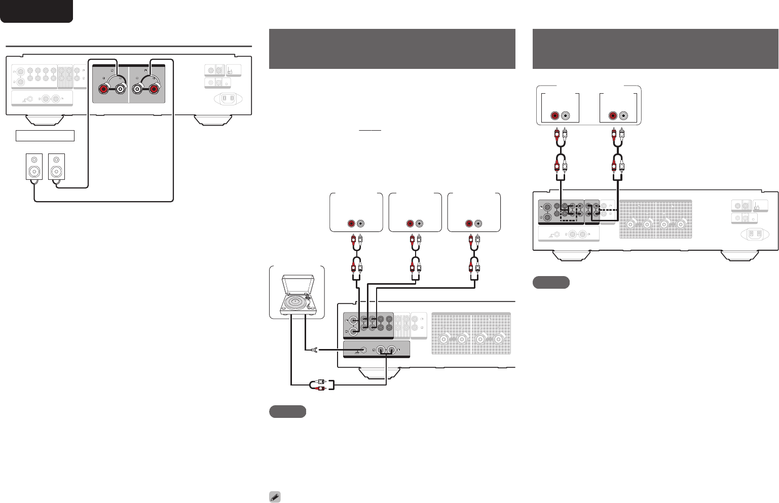
Connecting a playback
device
You can connect turntables, tuners, CD players and network
audio players to this unit.
Set the phono equalizer of this unit in the “PHONO” section of
the setting menu according to the type of turntable cartridge
to be connected. (v
p. 20)
If you set this unit’s input source to “PHONO” and you
accidentally increase the volume without having a turntable
connected, you may hear a hum noise from the speakers.
.
POWER AMP IN
POWER AMP IN
RECORDER-
RECORDER-
1
RECORDER-
RECORDER-
2
SPEAKERS
SPEAKERS
IMPEDANCE : 4
IMPEDANCE : 4㹼
16
16Ȑ
AUDIO OUT
AUDIO OUT
AUDIO IN
AUDIO IN
AUDIO IN
AUDIO IN
CD
CD
LINE-1
LINE-1
PHONO
PHONO
SIGNAL
SIGNAL
GND
GND
LINE-2
LINE-2
RECORDER-
RECORDER-
1
RECORDER-
RECORDER-
2
GND
AUDIO
OUT
L
R
AUDIO
OUT
LR
AUDIO
OUT
LR
AUDIO
OUT
LR
L
L
R
R
L
L
R
R
L
L
R
R
Network
audio
player
Tu n e r
Turntable
CD
player
NOTE
0
The earth terminal (SIGNAL GND) of this unit is not for safety
grounding purposes. If this terminal is connected when there is a lot
of noise, the noise can be reduced. Note that depending on the
turntable, connecting the ground line may have the reverse effect of
increasing noise. In this case, it is not necessary to connect the
ground line.
0
The PHONO input terminals are equipped with a short pin-plug.
Remove this plug to connect a record player. Store the removed short
pin-plug in a safe place so as not to lose it.
Connecting a recording
device
.
AC IN
AC IN
POWER AMP IN
POWER AMP IN
AUDIO IN
AUDIO IN
PHONO
PHONO
SIGNAL
SIGNAL
GND
GND
SPEAKERS
SPEAKERS
IMPEDANCE : 4
IMPEDANCE : 4㹼
16
16Ȑ
IN
IN
ID
ID
STEREO
STEREO
BI-AMP
BI-AMP
F.C.B.S.
F.C.B.S.
REMOTE CONTROL
REMOTE CONTROL
AMP MODE
AMP MODE
OUT
OUT
IN
IN
OUT
OUT
AUDIO IN
AUDIO IN
CD
CD
LINE-1
LINE-1
LINE-2
LINE-2
RECORDER-
RECORDER-
1
RECORDER-
RECORDER-
2
RECORDER-
RECORDER-
1
RECORDER-
RECORDER-
2
AUDIO OUT
AUDIO OUT
LR
L
L
R
R
L
L
R
R
AUDIO OUT
LR
AUDIO IN
Recording device
NOTE
0
Never insert the short-circuiting pin plug into the recording
output connectors (AUDIO OUT RECORDER). Doing so
could result in damage.
ENGLISH
9
Connecting multiple PM-KI RUBY units (F.C.B.S. connection)
The Marantz F.C.B.S. (Floating Control Bus System) is the high quality sound system for link control between multiple PM-KI RUBY units (up to 4 units). Each unit is controlled via its ID number
registered beforehand.
The ID numbers need to be set to an operating unit (master) and a subordinate unit (slave) receiving the command from the master. For slave units, register ID numbers in the order of command
reception from the master.
ID numbers can be set for units connected by F.C.B.S. to perform linked operations such as switching the input source, adjusting the volume, muting, adjusting the volume balance, adjusting the
sound quality and trimming the display brightness.
Furthermore, F.C.B.S. connection of multiple PM-KI RUBY units has the feature that switches this unit's output from stereo to monaural so that the unit can works as a monaural output amplifier.
Follow the respective instructions to make the necessary settings.
Preparation for F.C.B.S. connection
n
Making the F.C.B.S. connection
To use multiple PM-KI RUBY units, make this connection
in addition to audio connection.
For details on each connection feature, refer to the
respective instructions.
0
“Stereo complete bi-amp connection” (v
p. 11)
0
“Connection for 5.1 Multi-channel
Playback” (v p. 13)
Prepare the correct number of portable audio connection
cables for the number of units to be connected. Either of
the following types of connection cables are adequate.
0
Φ3.5 Monaural mini plug ON Φ3.5 monaural mini plug
connecting cable
.
0
Φ3.5 Stereo mini plug ON Φ3.5 stereo mini plug
connecting cable
.
NOTE
0
Do not use connecting cables that contain resistance.
n
Connection example
In the connection of the following example, an unit with ID
number 1 acts as a master amplifier to control all the other
slave units with ID numbers 2 to 4.
.
AC IN
AC IN
AUDIO IN
AUDIO IN
POWER AMP IN
POWER AMP IN
AUDIO IN
AUDIO IN
CD
CD
LINE-1
LINE-1
PHONO
PHONO
SIGNAL
SIGNAL
GND
GND
LINE-2
LINE-2
RECORDER-
RECORDER-
1
RECORDER-
RECORDER-
2
RECORDER-
RECORDER-
1
RECORDER-
RECORDER-
2
SPEAKERS
SPEAKERS
IMPEDANCE : 4
IMPEDANCE : 4㹼
16
16Ȑ
IN
IN
STEREO
STEREO
BI-AMP
BI-AMP
REMOTE CONTROL
REMOTE CONTROL
AMP MODE
AMP MODE
OUT
OUT
AUDIO OUT
AUDIO OUT
ID
ID
F.C.B.S.
F.C.B.S.
OUT
OUT
AC IN
AC IN
AUDIO IN
AUDIO IN
POWER AMP IN
POWER AMP IN
AUDIO IN
AUDIO IN
CD
CD
LINE-1
LINE-1
PHONO
PHONO
SIGNAL
SIGNAL
GND
GND
LINE-2
LINE-2
RECORDER-
RECORDER-
1
RECORDER-
RECORDER-
2
RECORDER-
RECORDER-
1
RECORDER-
RECORDER-
2
SPEAKERS
SPEAKERS
IMPEDANCE : 4
IMPEDANCE : 4㹼
16
16Ω
IN
IN
STEREO
STEREO
BI-AMP
BI-AMP
REMOTE CONTROL
REMOTE CONTROL
AMP MODE
AMP MODE
OUT
OUT
AUDIO OUT
AUDIO OUT
ID
ID
F.C.B.S.
F.C.B.S.
IN
IN
IN
IN
IN
IN
OUT
OUT
IN
IN
ID
ID
F.C.B.S.
F.C.B.S.
OUT
OUT
ID
ID
F.C.B.S.
F.C.B.S.
OUT
OUT
ID
ID
F.C.B.S.
F.C.B.S.
ID
ID
F.C.B.S.
F.C.B.S.
OUT
OUT
IN
IN
OUT
OUT
IN
IN
IN
IN
IN
IN
ID 1 Master
ID 2 Slave
ID 3 Slave
ID 4 Slave
Signal flow
0
The PM-KI RUBY F.C.B.S. function is only valid between
the same PM-KI RUBY models.
0
To turn the power of multiple F.C.B.S.-connected units ON/
OFF, switch the power ON in order of lowest to highest ID
number, and switch the power OFF in order of highest to
lowest ID number.
ENGLISH
10
OverviewConnectionsPlaybackSettingsTipsAppendix
n
How to set ID number for F.C.B.S.
.
AC IN
AC IN
AUDIO IN
AUDIO IN
POWER AMP IN
POWER AMP IN
AUDIO IN
AUDIO IN
CD
CD
LINE-1
LINE-1
PHONO
PHONO
SIGNAL
SIGNAL
GND
GND
LINE-2
LINE-2
RECORDER-
RECORDER-
1
RECORDER-
RECORDER-
2
RECORDER-
RECORDER-
1
RECORDER-
RECORDER-
2
SPEAKERS
SPEAKERS
IMPEDANCE : 4
IMPEDANCE : 4㹼
16
16Ȑ
IN
IN
ID
ID
STEREO
STEREO
BI-AMP
BI-AMP
F.C.B.S.
F.C.B.S.
REMOTE CONTROL
REMOTE CONTROL
AMP MODE
AMP MODE
OUT
OUT
IN
IN
OUT
OUT
AUDIO OUT
AUDIO OUT
INPUT
SELECTOR
X
F.C.B.S. ID
1
While holding F.C.B.S. ID on the rear panel,
press X.
2
Turn INPUT SELECTOR on the unit to select
an ID number.
0
For a master unit, ID number 1 needs to be
assigned. For a slave unit, set any of ID numbers 2
to 4.
3
Turn the unit off.
4
Again turn the unit on.
The ID number appears on the display for around 3
seconds.
0
The setting is saved.
0
The unit registered as a slave shows “SLAVE” on the
display.
0
If using this unit by itself as a stereo amplifier, set the ID
number to “0”. (Default setting is “0”.)
0
If the ID number is set to a number other than “0”, this unit
cannot be used for standalone operation.
Stereo complete bi-amp connection
This mode enables the two amplifiers connected to this unit
to function as one monaural amplifier. To use this mode, two
F.C.B.S. connected PM-KI RUBY units are required.
To switch the mode, use the AMP MODE switch on the rear
panel while the power is off.
If this unit is set to the bi-amp mode, “BI-AMP” appears on the
display.
In bi-amp mode, connect to the left channel input connector.
The right channel input is disabled.
The same signals are output from the left and right speaker
terminals.
0
Be sure to turn the power off before operating the AMP
MODE switch. Settings can be configured when the power
is turned on.
0
When in bi-amp mode, the R channel input connectors
cannot be used.
0
When in bi-amp mode, the signals input into the L channel
are output from both channels. Therefore, the same signals
are output from the L channel and R channel in
RECORDER OUT, headphones jack.
0
Speaker systems connected using complete bi-amp
connections must support bi-amp connections. Before
connecting your speakers, check in the instruction manual
that came with the speakers or contact the manufacturer to
confirm whether they support bi-amp connection.
ENGLISH
11
.
POWER AMP IN
POWER AMP IN
AUDIO IN
AUDIO IN
PHONO
PHONO
SIGNAL
SIGNAL
GND
GND
RECORDER-
RECORDER-
1
RECORDER-
RECORDER-
2
IN
IN
REMOTE CONTROL
REMOTE CONTROL
OUT
OUT
AUDIO OUT
AUDIO OUT
SPEAKERS
SPEAKERS
AUDIO IN
AUDIO IN
CD
CD
LINE-1
LINE-1
LINE-2
LINE-2
RECORDER-
RECORDER-
1
RECORDER-
RECORDER-
2
AC IN
AC IN
ID
ID
STEREO
STEREO
BI-AMP
BI-AMP
F.C.B.S.
F.C.B.S.
AMP MODE
AMP MODE
OUT
OUT
IN
IN
POWER AMP IN
POWER AMP IN
AUDIO IN
AUDIO IN
PHONO
PHONO
SIGNAL
SIGNAL
GND
GND
RECORDER-
RECORDER-
1
RECORDER-
RECORDER-
2
IN
IN
REMOTE CONTROL
REMOTE CONTROL
OUT
OUT
AUDIO OUT
AUDIO OUT
SPEAKERS
SPEAKERS
AUDIO IN
AUDIO IN
CD
CD
LINE-1
LINE-1
LINE-2
LINE-2
RECORDER-
RECORDER-
1
RECORDER-
RECORDER-
2
AC IN
AC IN
ID
ID
STEREO
STEREO
BI-AMP
BI-AMP
F.C.B.S.
F.C.B.S.
AMP MODE
AMP MODE
OUT
OUT
IN
IN
MF / HF
LF
MF / HF
LF
L
L
R
R
Super Audio CD player, etc.
: Signal flow
Set to “BI-AMP”.
Set to “BI-AMP”.
Set PM-KI RUBY
for L channel to
ID 1
To power outlet.
To power outlet.
Remove shorting bar
Remove shorting bar
Remove shorting bar
Remove shorting bar
L channel
speaker
R channel
speaker
When in bi-amp mode, connect to the L
channel input connector.
Set PM-KI RUBY
for R channel to
ID 2
ENGLISH
12
OverviewConnectionsPlaybackSettingsTipsAppendix
Connection for 5.1 Multi-channel Playback
Three PM-KI RUBY units can be connected by F.C.B.S. and used through linked operation. For details on F.C.B.S. connection, see “Examples of Connections” ( (v p. 10)).
Connect the outputs of players that have 5.1 channel analog outputs to each of the three units.
If using an active subwoofer, see the instruction manual that came with the subwoofer for further instructions.
Set the ID numbers for the three amplifiers as explained in How to set ID number for F.C.B.S. (v
p. 11)
0
When the ID 1 unit is operated, ID 2 and ID 3 units will operate in sync.
.
POWER AMP IN
POWER AMP IN
AUDIO IN
AUDIO IN
PHONO
PHONO
SIGNAL
SIGNAL
GND
GND
RECORDER-
RECORDER-
1
RECORDER-
RECORDER-
2
IN
IN
REMOTE CONTROL
REMOTE CONTROL
OUT
OUT
AUDIO OUT
AUDIO OUT
SPEAKERS
SPEAKERS
AC IN
AC IN
ID
ID
STEREO
STEREO
BI-AMP
BI-AMP
F.C.B.S.
F.C.B.S.
AMP MODE
AMP MODE
OUT
OUT
IN
IN
AUDIO IN
AUDIO IN
CD
CD
LINE-1
LINE-1
LINE-2
LINE-2
RECORDER-
RECORDER-
1
RECORDER-
RECORDER-
2
POWER AMP IN
POWER AMP IN
AUDIO IN
AUDIO IN
PHONO
PHONO
SIGNAL
SIGNAL
GND
GND
RECORDER-
RECORDER-
1
RECORDER-
RECORDER-
2
IN
IN
REMOTE CONTROL
REMOTE CONTROL
OUT
OUT
AUDIO OUT
AUDIO OUT
SPEAKERS
SPEAKERS
AC IN
AC IN
ID
ID
STEREO
STEREO
BI-AMP
BI-AMP
F.C.B.S.
F.C.B.S.
AMP MODE
AMP MODE
OUT
OUT
IN
IN
AUDIO IN
AUDIO IN
CD
CD
LINE-1
LINE-1
LINE-2
LINE-2
RECORDER-
RECORDER-
1
RECORDER-
RECORDER-
2
POWER AMP IN
POWER AMP IN
AUDIO IN
AUDIO IN
PHONO
PHONO
SIGNAL
SIGNAL
GND
GND
RECORDER-
RECORDER-
1
RECORDER-
RECORDER-
2
IN
IN
REMOTE CONTROL
REMOTE CONTROL
OUT
OUT
AUDIO OUT
AUDIO OUT
SPEAKERS
SPEAKERS
AC IN
AC IN
ID
ID
STEREO
STEREO
BI-AMP
BI-AMP
F.C.B.S.
F.C.B.S.
AMP MODE
AMP MODE
OUT
OUT
IN
IN
AUDIO IN
AUDIO IN
CD
CD
LINE-1
LINE-1
LINE-2
LINE-2
RECORDER-
RECORDER-
1
RECORDER-
RECORDER-
2
FRONT RFRONT LSURROUND R
MULTI CHANNEL AUDIO OUT
SURROUND LSUB-WOOFERCENTER
L
L
R
L
R
L
R
LL
R
: Signal flow
To power
outlet.
To power
outlet.
To power
outlet.
Rear speaker
(Right Surround)
Rear speaker (Left
Surround)
Center speaker
Front speaker
(Right)
Front speaker
(Left)
SACD multi-channel player, etc.
Set to “STEREO”.Set to “STEREO”.
Set to “STEREO”.
For front L/R speakers Set
PM-KI RUBY to ID 1
For center speaker Set
PM-KI RUBY to ID 2
For surround speakers Set
PM-KI RUBY to ID 3
ENGLISH
13
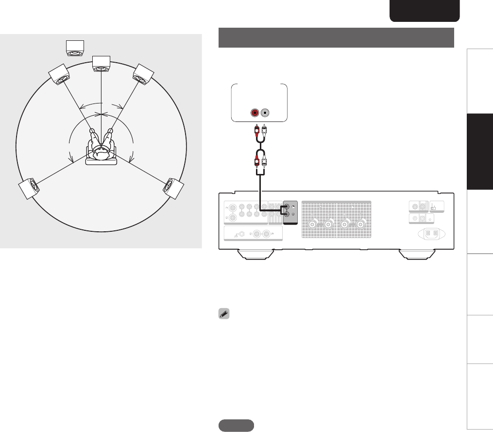
n
Speaker Positioning for Super Audio
Multi-channel Sound
In order to enjoy Super Audio CD multi-channel sound
with the best possible acoustics, it is recommended to
position speakers as specified in ITU-R BS.775-1 of the
International Telecommunication Union (ITU). Super
Audio CD multichannel discs are recorded and mixed so
as to achieve the optimum effect with a speaker system
laid out as specified in ITU-R BS.775-1.
0
With Super Audio CD multi-channel discs, the music
signals are basically recorded using 5 channels (3 - 6
channels sometimes), but in some cases, LFE (for
subwoofer) is recorded as a sixth channel.
0
Each disc indicates how many channels have been
recorded on it.
0
The basic layout is 3 speakers in the front and 2 in the
back since multi-channel discs usually have 5
channels. The 2 front, 1 center and 2 surround (rear)
speakers should be set in a circle around the listening
point. If using speakers of differing sizes, adjust volume
balance from the amplifier.
0
The location of the subwoofer in the figure is just for
explanatory purposes. It can be located anywhere in
the room. For connection and positioning instructions,
see the instruction manual that came with the
subwoofer.
.
60°
Subwoofer
Center
speaker
Front speaker
(Left)
Front speaker
(Right)
Rear
speaker
(Left Surround)
Rear
speaker
(Right Surround)
approx.110°
approx.110°
Recommended
listening position
0
ITU (International Telecommunication Union)
The ITU is a special organization of the United Nations. It
consists of a number of organs, one of which is the Radio
Broadcasting Section.
ITU-R BS in the recommendation which consists of standards
relating to broadcasting (audio) operations, one of which is
the ITU-R BS.775-1 which governs “multi-channel stereo
sound systems”.
Connecting a pre-amplifier
If you use a pre-amplifier, connect it as shown below, and
then you can use this unit as a power amplifier.
.
AC IN
AC IN
AUDIO IN
AUDIO IN
AUDIO IN
AUDIO IN
CD
CD
LINE-1
LINE-1
PHONO
PHONO
SIGNAL
SIGNAL
GND
GND
LINE-2
LINE-2
RECORDER-
RECORDER-
1
RECORDER-
RECORDER-
2
RECORDER-
RECORDER-
1
RECORDER-
RECORDER-
2
SPEAKERS
SPEAKERS
IMPEDANCE : 4
IMPEDANCE : 4㹼
16
16Ȑ
IN
IN
ID
ID
STEREO
STEREO
BI-AMP
BI-AMP
F.C.B.S.
F.C.B.S.
REMOTE CONTROL
REMOTE CONTROL
AMP MODE
AMP MODE
OUT
OUT
IN
IN
OUT
OUT
AUDIO OUT
AUDIO OUT
POWER AMP IN
POWER AMP IN
LR
L
L
R
R
AUDIO
OUT
Pre-amplifier
1
Turn INPUT SELECTOR on the main unit to
select the input source to “PWR AMP”.
0
You cannot use the input source switching buttons on the
remote control unit to select “PWR AMP”.
0
Volume adjustment, muting and adjustments to the volume
balance (LEVEL) and sound quality (BASS/TREBLE) are
not possible when the input source is “PWR AMP”. Adjust
these via the pre-amplifier connected to this unit.
0
When the input source is set to “PWR AMP”, you cannot
use the remote control unit to select the input source.
NOTE
0
When the input source is “PWR AMP”, the main unit
outputs at maximum volume. Check the output level on the
input device before playing it and adjust the volume
accordingly.
ENGLISH
14
OverviewConnectionsPlaybackSettingsTipsAppendix
Connecting devices with
remote control connectors
Performing operations by RC on
this unit without visual contact
You can connect an external IR receiver to the REMOTE
CONTROL connectors to perform operations on this unit with
the supplied remote control unit without visual contact. This
might be necessary if the unit is hidden in a cupboard or
corner, so you can’t directly point with the remote control unit
to the device.
.
AC IN
AC IN
IN
IN
ID
ID
STEREO
STEREO
BI-AMP
BI-AMP
F.C.B.S.
F.C.B.S.
REMOTE CONTROL
REMOTE CONTROL
AMP MODE
AMP MODE
OUT
OUT
IN
IN
OUT
OUT
RC OUT
IN
IN
REMOTE CONTROL
REMOTE CONTROL
OUT
OUT
Infrared
retransmitter
Infrared
sensor
Remotely connecting Marantz audio
devices
You can transmit remote control signals simply by connecting
a Marantz audio device to the REMOTE CONTROL IN/OUT
connectors using the remote connection cable provided with
the device.
Set the remote control switch located on the rear panel of the
connected audio component to “EXTERNAL” to use this
feature.
.
AC IN
AC IN
ID
ID
STEREO
STEREO
BI-AMP
BI-AMP
F.C.B.S.
F.C.B.S.
AMP MODE
AMP MODE
OUT
OUT
IN
IN
IN
IN
REMOTE CONTROL
REMOTE CONTROL
OUT
OUT
IN
IN
REMOTE CONTROL
REMOTE CONTROL
OUT
OUT
Connecting the power cord
After completing all the connections, insert the power plug
into the power outlet.
.
SPEAKERS
SPEAKERS
IMPEDANCE : 4
IMPEDANCE : 4㹼
16
16Ȑ
IN
IN
ID
ID
STEREO
STEREO
BI-AMP
BI-AMP
F.C.B.S.
F.C.B.S.
REMOTE CONTROL
REMOTE CONTROL
AMP MODE
AMP MODE
OUT
OUT
IN
IN
OUT
OUT
AC IN
AC IN
Power cord (supplied)
To household power outlet
(AC 230 V, 50/60 Hz)
ENGLISH
15
Playback
n
Contents
Turning the power on16
Selecting the input source16
Adjusting the volume16
Turning off the sound temporarily (Muting)16
Adjusting the volume balance (LEVEL) and sound quality
(BASS/TREBLE)17
Switching the display’s brightness18
Having the illumination lamp off18
Playing CDs18
Recording18
.
VOLUME
df
REMOTE MODE AMP
MODE/TRIM
DISPLAY
INPUT
df
MUTE
uio
p
AMP
X
TONE
ENTER
Turning the power on
1
Press X on the main unit to turn the power on.
0
The power indicator lights in blue.
0
Press X AMP on the remote control unit to turn on power
from standby mode.
0
You can also turn the INPUT SELECTOR on the main unit
when the unit is in standby mode to turn on the power.
n
Switching the power to standby
1
Press X AMP on the remote control.
The unit switches to standby mode, and the STANDBY
indicator lights red.
NOTE
0
Power continues to be supplied to some of the circuitry
even when the power is in the standby mode. When
leaving home for long periods of time or when going on
vacation, either press X on the main unit to turn off the
power, or unplug the power cord from the power outlet.
Selecting the input source
1
Use INPUT df to select the input source to be
played back.
The selected input source appears on the display.
0
You can also select the input source by turning INPUT
SELECTOR on the main unit.
Adjusting the volume
1
Use VOLUME df to adjust the volume.
0
You can also adjust the volume by turning VOLUME on the
main unit.
Turning off the sound temporarily
(Muting)
1
Press MUTE.
“MUTE” appears on the display and the sound is
muted.
0
To cancel mute, press MUTE again.
0
You can set the volume to be decreased when MUTE is
pressed. Set this as desired through “ATT LEVEL” in the
menu. (v p. 20)
ENGLISH
16
OverviewConnectionsPlaybackSettingsTipsAppendix
Adjusting the volume balance (LEVEL) and sound quality (BASS/TREBLE)
n
Adjusting LEVEL
The volume level of the left and right channels can be
trimmed in 0.5 dB steps across a 0.0 - -9.0 dB range.
The factory default setting is 0.0 dB (maximum).
1
Press MODE/TRIM.
The unit enters LEVEL adjustment mode.
0
If the slave (v p. 10) is connected by F.C.B.S., the
device for to adjust the volume balance (LEVEL) and
sound quality (BASS/TREBLE) can be switched by
pressing this button.
2
Press op to select the channel that you wish
to configure (L or R).
The level value of the selected channel flashes.
3
Use ui to adjust the volume.
0
If there is no operation for 15 seconds, the setting is
committed and the unit returns to the standard display.
4
Press ENTER.
This exits LEVEL adjustment mode and enters BASS
adjustment mode. Follow steps 3 onward of “Adjusting
BASS” to adjust the bass.
n
Adjusting BASS
The bass volume can be adjusted in 1 dB steps across a
-6 - +6 dB range. The factory default setting is 0 dB.
1
Press MODE/TRIM.
The unit enters LEVEL adjustment mode.
2
Press ENTER to select “BASS”.
The unit enters BASS adjustment mode.
3
Press ui to adjust the bass volume.
0
If there is no operation for 15 seconds, the setting is
committed and the unit returns to the standard display.
4
Press ENTER.
This exits BASS adjustment mode and enters TREBLE
adjustment mode. Follow steps 3 onward of “Adjusting
TREBLE” to adjust the treble.
0
Settings are not applied when tone control is turned off.
Press TONE to turn on tone control (TONE indicator
lights).
n
Adjusting TREBLE
The treble volume can be adjusted in 1 dB steps across a
-6 - +6 dB range. The factory default setting is 0 dB.
1
Press MODE/TRIM.
The unit enters LEVEL adjustment mode.
2
Press ENTER twice to select “TREBLE”.
The unit enters TREBLE adjustment mode.
3
Press ui to adjust the treble volume.
0
If there is no operation for 15 seconds, the setting is
committed and the unit returns to the standard display.
4
Press ENTER.
This exits TREBLE adjustment mode and returns to the
normal display.
0
Settings are not applied when tone control is turned off.
Press TONE to turn on tone control (TONE indicator
lights).
ENGLISH
17
Switching the display’s brightness
The display brightness can be adjusted between four levels.
Switching the display off reduces a source of noise that
The display brightness is set to most brightly by default.
0
If you operate the VOLUME knob or another control when
the display is off, the display turns on again. When
operation is finished, the display turns off automatically
after approximately 2 seconds.
0
When the display brightness is set to off, the illumination
lamp turns off too.
Having the illumination lamp off
1
Press and hold DISPLAY for 2 seconds or
more while the illumination lamp is lit.
Press and hold DISPLAY for two seconds and longer
while the lamp is always off to return to the normal
setting.
Playing CDs
This section uses playback from a CD as an example.
1
Press X on the main unit to turn the power on.
2
Use INPUT df to switch the input source to
“CD”.
“CD” appears on the display.
3
Playback the CD.
4
Use VOLUME df to adjust the volume.
Recording
Audio signals input into this unit can be output to an external
recording device. When recording audio from a playback
device connected to this unit, audio can be recorded with the
playback device still connected to this unit.
1
Press X on the main unit to turn the power on.
2
Use INPUT df to switch to the input source
from which you want to record.
The selected input source is displayed on the display.
3
Recording starts.
0
For information on operations, see the owner’s
manual of the recording device.
ENGLISH
18
OverviewConnectionsPlaybackSettingsTipsAppendix
Settings
Menu map
By default, this unit has recommended settings defined. You can customize this unit based on your existing system and your preferences.
Setting itemsDescriptionPage
PHONOSets the phono equalizer of this unit according to the type of the turntable cartridge to be connected.20
AUTO STBY
(Auto Standby)
Sets whether to automatically switch the unit to the standby mode when there is no audio input and no operations are
performed for more than 30 minutes.
20
ATT LEVEL
(Attenuation Level)
Sets how far the volume is decreased when the MUTE button is pressed.20
Menu operation
.
uio
ENTER
SETUP
1
Press SETUP.
The menu is displayed on the display.
2
Use ui to select the menu to be set or
operated, then press ENTER.
3
Use ui to change to desired setting.
4
Press ENTER to enter the setting.
0
To return to the previous item, press o.
0
Exiting the Menu, press SETUP while the menu is
displayed. The display returns to the normal display.
ENGLISH
19
PHONO
Sets the phono equalizer of this unit according to the type of
the turntable cartridge to be connected.
MM
(Default):
Set this for an MM cartridge.
MC:Set this for an MC cartridge.
NOTE
0
The audio is muted for around 4 seconds when this setting
is changed.
AUTO STBY (Auto Standby)
Sets whether to automatically switch the unit to the standby
mode when there is no input signal and operation for 30
minutes.
ON
(Default):
Enable Auto Standby mode.
OFF:Disable Auto Standby mode.
0
The display will show the remaining time for three minutes
before the units enters standby mode.
0
In F.C.B.S. connection, only the ID 1 master unit activates
Auto Standby mode. If the ID 1 master unit is operated with
no audio input, set the Auto Standby mode to off.
ATT LEVEL (Attenuation
Level)
Sets how far the volume is decreased when the MUTE button
is pressed.
-20 dB / -40 dB / -∞(Default: -∞)
0
“ATT” appears on the display if the MUTE button is
pressed when -20 dB or -40 dB is set.
0
“MUTE” appears on the display if the MUTE button is
pressed when -∞ is set.
0
Press the MUTE button again to cancel the setting and
return to the original volume.
ENGLISH
20
OverviewConnectionsPlaybackSettingsTipsAppendix
Tips
n
Contents
Tips
I want to set how far the volume is decreased when the
MUTE button is pressed22
I want to turn the illumination lamps on both sides of the
unit main panel off22
I want to use two or more of PM-KI RUBY units for high
quality playback22
I want to use this unit’s remote control to operate a
Marantz CD player22
I want to use this unit as a power amplifier22
Troubleshooting
Power does not turn on / Power is turned off23
Operations cannot be performed through the remote
control unit24
No sound comes out24
Desired sound does not come out25
Sound is interrupted or noise occurs25
Error messages25
ENGLISH
21
Tips
I want to set how far the volume is decreased when the MUTE button is pressed
0
-20 dB, -40 dB or - ∞ can be set. (v p. 20)
I want to turn the illumination lamps on both sides of the unit main panel off
0
Set the illumination lamp to off. (v
p. 18)
I want to use two or more of PM-KI RUBY units for high quality playback
0
Use the stereo complete bi-amp connections. (v p. 11)
0
Use the multi-channel playback connections. (v p. 13)
I want to use this unit’s remote control to operate a Marantz CD player
0
Press the REMOTE MODE CD button to switch the remote control to the CD player operating mode. (v p. 7)
0
Also, refer to the instruction manual of the CD player.
I want to use this unit as a power amplifier
0
Connect the pre amplifier to the POWER AMP IN connectors of this unit. (v
p. 14)
ENGLISH
22
OverviewConnectionsPlaybackSettingsTipsAppendix
Troubleshooting
If a problem should arise, first check the following:
1.Are the connections correct?
2.Is the set being operated as described in the owner’s manual?
3.Are the other devices operating properly?
If this unit does not operate properly, check the corresponding symptoms in this section.
If the symptoms do not match any of those described here, consult your dealer as it could be due to a fault in this unit. In this case, disconnect the power immediately and contact the store where
you purchased this unit.
n
Power does not turn on / Power is turned off
SymptomCause / SolutionPage
Power is not turned on.
0
Check whether the power plug is correctly inserted into the power outlet.15
Power automatically turns off.
0
The Auto Standby mode is on. When approx. 30 minutes pass with no audio input and no operations on the unit, this unit
automatically enters the standby mode. To disable Auto Standby mode, set “AUTO STBY” on the menu to “OFF”.
20
Power turns off and the STANDBY
indicator flashes in red approx. every 0.5
seconds.
0
The protection circuit has been activated due to a rise in temperature within this unit. Turn the power off, wait about an hour until this
unit cools down sufficiently, and then turn the power on again.
26
0
Please re-install this unit in a place having good ventilation.-
0
Check the speaker connections. The protection circuit may have been activated because speaker cable core wires came in contact
with each other or a core wire was disconnected from the connector and came in contact with the rear panel of this unit. After
unplugging the power cord, take corrective action such as firmly re-twisting the core wire or taking care of the connector, and then
reconnect the wire.
8
0
Turn down the volume and turn on the power again.16
0
This unit’s amplifier circuit has failed. Unplug the power cord and contact our customer service center.-
ENGLISH
23
n
Operations cannot be performed through the remote control unit
SymptomCause / SolutionPage
Operations cannot be performed
through the remote control unit.
0
Batteries are worn out. Replace with new batteries.2
0
Operate the remote control unit within a distance of about 7 m from this unit and at an angle of within 30°.2
0
Remove any obstacle between this unit and the remote control unit.-
0
Insert the batteries in the proper direction, checking the q and w marks.
2
0
The set’s remote control sensor is exposed to strong light (direct sunlight, inverter type fluorescent bulb light, etc.). Move the set to a
place in which the remote control sensor will not be exposed to strong light.
-
0
When using a 3D video device, the remote control unit of this unit may not function due to effects of infrared communications
between units (such as TV and glasses for 3D viewing). In this case, adjust the direction of units with the 3D communications
function and their distance to ensure they do not affect operations from the remote control unit of this unit.
-
0
Press the REMOTE MODE AMP button to switch the remote control operating mode to “AMP”.6
n
No sound comes out
SymptomCause / SolutionPage
No sound comes out of speakers.
0
Check the connections for all devices.8
0
Insert connection cables all the way in.-
0
Check that input connectors and output connectors are not reversely connected.-
0
Check cables for damage.-
0
Check that speaker cables are properly connected. Check that cable core wires come in contact with the metal part on speaker
terminals.
8
0
Securely tighten the speaker terminals. Check speaker terminals for looseness.8
0
Check that the proper input source is selected.16
0
Adjust the volume.16
0
Cancel the muting mode.16
0
No sound is output from the speakers when headphones are connected.4
ENGLISH
24
OverviewConnectionsPlaybackSettingsTipsAppendix
n
Desired sound does not come out
SymptomCause / SolutionPage
No sound comes out of a specific
speaker.
0
Check that speaker cables are properly connected.8
0
Adjust the left and right channel balance.17
The left and right of stereo sound is
reversed.
0
Check whether the left and right speakers are connected to the correct speaker terminals.8
n
Sound is interrupted or noise occurs
SymptomCause / SolutionPage
When playing a record, the sound is
distorted.
0
Adjust to a proper needle pressure.-
0
Check the tip of the needle.-
0
Replace the cartridge.-
When playing a record, a humming
noise comes out of the speakers.
0
Check that the turntable is connected correctly.9
0
If there is a TV or AV device near the turntable, such devices may affect the playback sound. Install the turntable in a location as far
away as possible from the TV or other AV devices.
-
When playing a record, a humming
noise comes out of the speakers when
the volume is high. (Howling
phenomenon)
0
Install the turntable and speakers as far from each other as possible.9
0
The vibrations from the speakers are being transmitted to the player through the floor. Use cushions, etc., to absorb the speakers’
vibrations.
-
Audio sources recorded through this unit
are distorted.
0
If two recording devices are connected to this unit, turn on the power of both recording devices when recording. If the power of only
one recording device is turned on, the recording device that is turned off may cause distortion of the audio recorded to the other
recording device, depending on the type of recording device.
18
Error messages
When multiple PM-KI RUBY units are connected by F.C.B.S., the error messages described in the table below may be displayed on the display. In such a case, ID number setting or remote cable
connection may be in failure. Check the ID number or remote cable connection, referring to the table below. For details on ID number setting, see “How to set ID number for F.C.B.S.” (v p. 11).
Indication
MeaningCause / Solution
ERROR 02Multiple amplifiers take ID No.2.
0
Assign different ID numbers to the amplifiers.
ERROR 03Multiple amplifiers take ID No.3.
ERROR 04Multiple amplifiers take ID No.4.
ERROR 11The amplifiers with ID No.2-4 cannot communicate with the amplifier with ID No.1.
0
If the amplifier with ID No.1 is not on, turn it ON.
0
Check that the remote cable is properly connected.
ERROR 12The amplifier with ID No.1 cannot communicate with the amplifiers with ID No.2-4.
0
If multiple amplifiers take ID No.1, set ID numbers properly.
0
If the amplifier with ID No.1 is connected to the amplifier with ID No.0, set ID
numbers properly.
0
Check that the remote cable is properly connected.
ENGLISH
25
Appendix
Explanation of terms
MM/MC cartridge
There are two types--MM (Moving Magnet) and MC (Moving
Coil)--of cartridges for turntable. As the output levels for these
two types of cartridges differ, the setting of the phono
equalizer that is mounted in this unit must be switched
according to the type of cartridge for your turntable. Change
this setting in the “PHONO” section of the setting menu.
(v
p. 20)
Speaker impedance
This is an AC resistance value, indicated in Ω (ohms).
Greater power can be obtained when this value is smaller.
Protection circuit
This is a function to prevent damage to devices within the
power supply when an abnormality such as an overload,
excess voltage occurs or over temperature for any reason.
Trademark information
.
Adobe, the Adobe logo and Reader are either registered
trademarks or trademarks of Adobe Systems Incorporated in
the United States and/or other countries.
ENGLISH
26
OverviewConnectionsPlaybackSettingsTipsAppendix
Specifications
0
RMS Power output (Simultaneous drive of both channels) :100 W x 2 (8 Ω/ohms load, 1 kHz, T.H.D. 0.05 %)
200 W x 2 (4 Ω/ohms load, 1 kHz, T.H.D. 0.1 %)
0
Total harmonic distortion
(1 kHz, simultaneous drive of both channels, 100 W, 8 Ω/ohms load) :
0.005 %
0
Frequency response (CD, 1 W, 8 Ω/ohms load) :5 Hz – 50 kHz ±3 dB
Gebruikershandleiding.com neemt misbruik van zijn services uitermate serieus. U kunt hieronder aangeven waarom deze vraag ongepast is. Wij controleren de vraag en zonodig wordt deze verwijderd.
Product:
Spelregels forum
Om tot zinvolle vragen te komen hanteren wij de volgende spelregels:
lees eerst de handleiding door;
controleer of uw vraag al eerder door iemand anders is gesteld;
probeer uw vraag zo duidelijk mogelijk te stellen;
heeft u een probleem en al geprobeerd om dit op te lossen, vermeld dit erbij aub;
heeft u een oplossing gekregen van een bezoeker dan horen wij dat graag in dit forum;
wilt u een reactie geven op een vraag of antwoord, gebruik dan niet dit formulier maar klik op de knop 'reageer op deze vraag';
uw vraag wordt direct op de website gezet; vermijd daarom persoonlijke gegevens in te vullen;
Belangrijk! Als er een antwoord wordt gegeven op uw vraag, dan is het voor de gever van het antwoord nuttig om te weten als u er wel (of niet) mee geholpen bent! Wij vragen u dus ook te reageren op een antwoord.
Belangrijk! Antwoorden worden ook per e-mail naar abonnees gestuurd. Laat uw emailadres achter op deze site, zodat u op de hoogte blijft. U krijgt dan ook andere vragen en antwoorden te zien.
Abonneren
Abonneer u voor het ontvangen van emails voor uw Marantz PM-KI Ruby bij:
nieuwe vragen en antwoorden
nieuwe handleidingen
U ontvangt een email met instructies om u voor één of beide opties in te schrijven.
Ontvang uw handleiding per email
Vul uw emailadres in en ontvang de handleiding van Marantz PM-KI Ruby in de taal/talen: Engels als bijlage per email.
De handleiding is 1,05 mb groot.
U ontvangt de handleiding per email binnen enkele minuten. Als u geen email heeft ontvangen, dan heeft u waarschijnlijk een verkeerd emailadres ingevuld of is uw mailbox te vol. Daarnaast kan het zijn dat uw internetprovider een maximum heeft aan de grootte per email. Omdat hier een handleiding wordt meegestuurd, kan het voorkomen dat de email groter is dan toegestaan bij uw provider.
Uw handleiding is per email verstuurd. Controleer uw email
Als u niet binnen een kwartier uw email met handleiding ontvangen heeft, kan het zijn dat u een verkeerd emailadres heeft ingevuld of dat uw emailprovider een maximum grootte per email heeft ingesteld die kleiner is dan de grootte van de handleiding.
Er is een email naar u verstuurd om uw inschrijving definitief te maken.
Controleer uw email en volg de aanwijzingen op om uw inschrijving definitief te maken
U heeft geen emailadres opgegeven
Als u de handleiding per email wilt ontvangen, vul dan een geldig emailadres in.
Uw vraag is op deze pagina toegevoegd
Wilt u een email ontvangen bij een antwoord en/of nieuwe vragen? Vul dan hier uw emailadres in.