Using vTuner to add Internet Radio stations to favorites125
Playing back files stored on a PC and NAS126
Applying media sharing settings127
Playing back files stored on a PC and NAS128
ContentsConnectionsPlaybackSettingsTipsAppendix
3
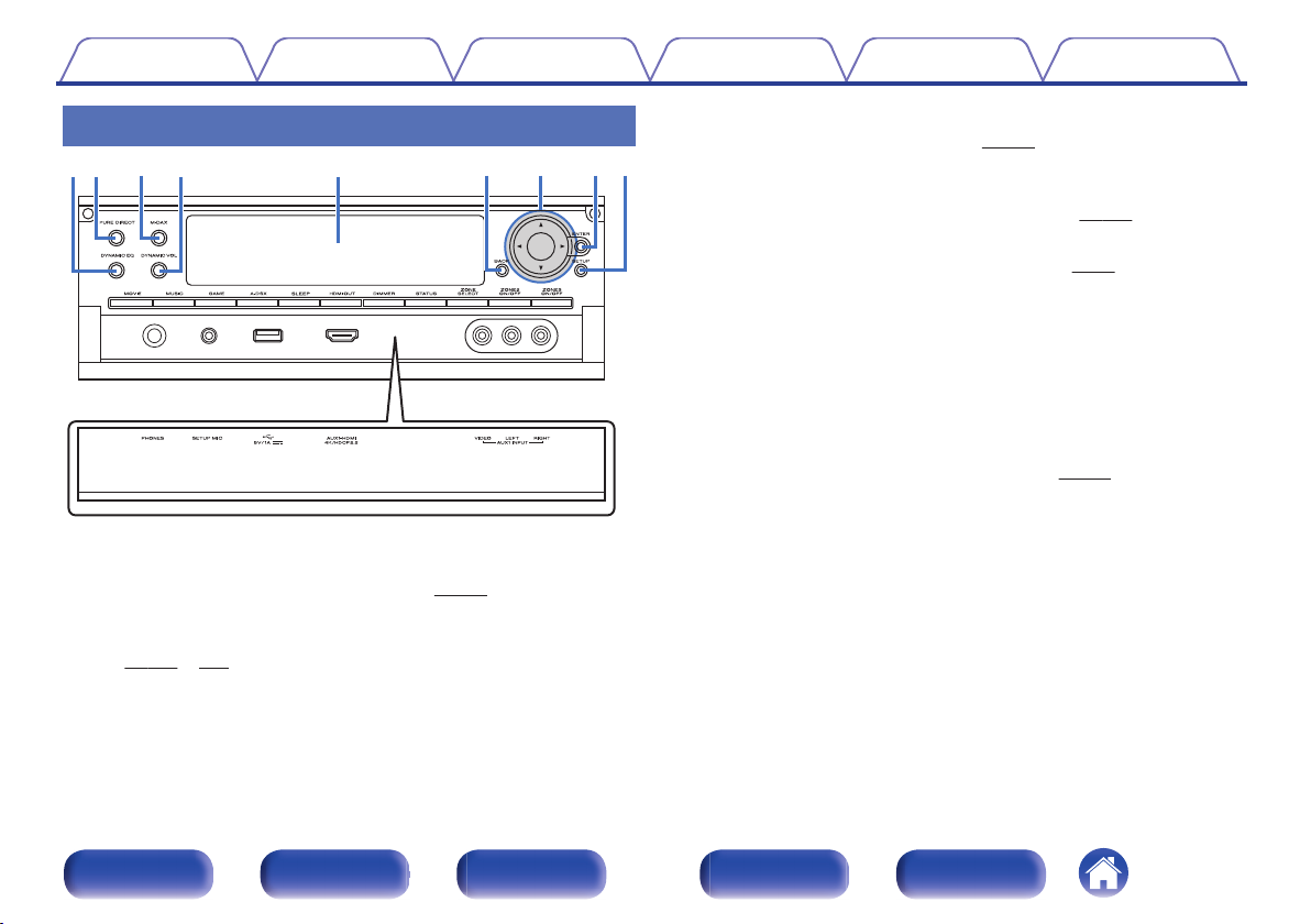
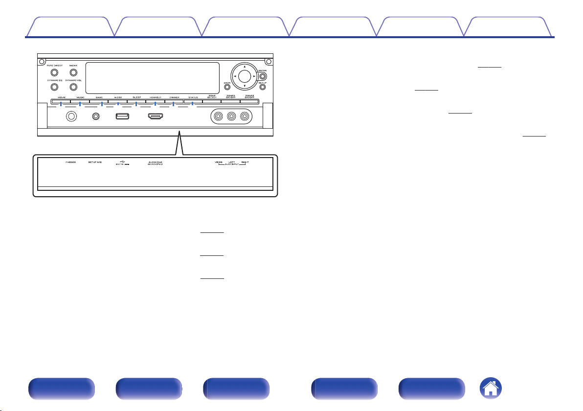
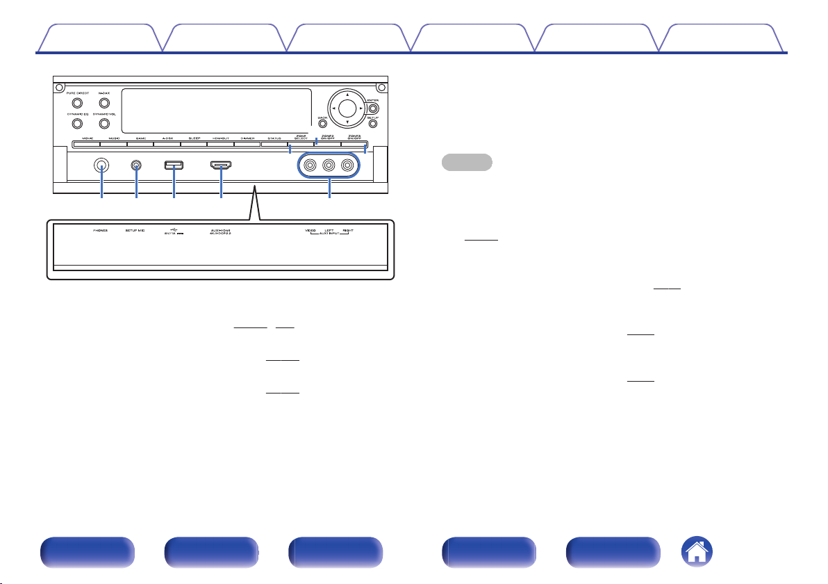
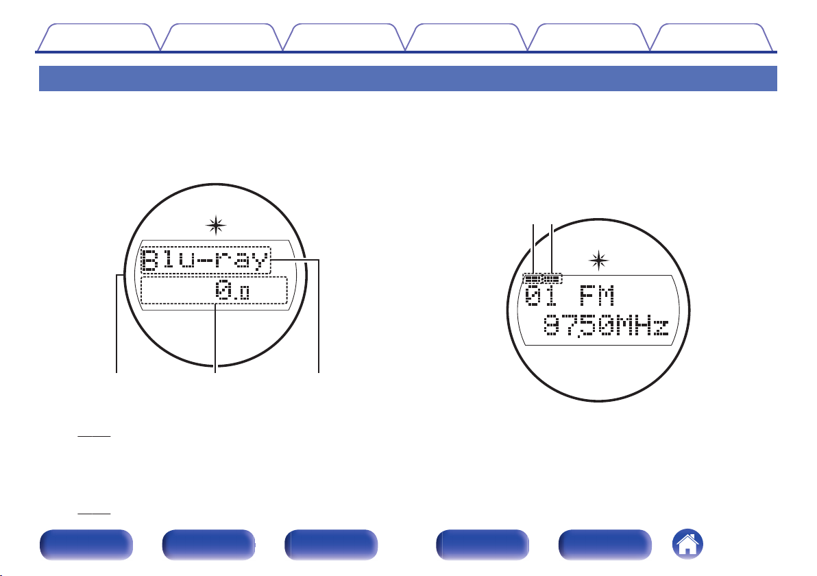
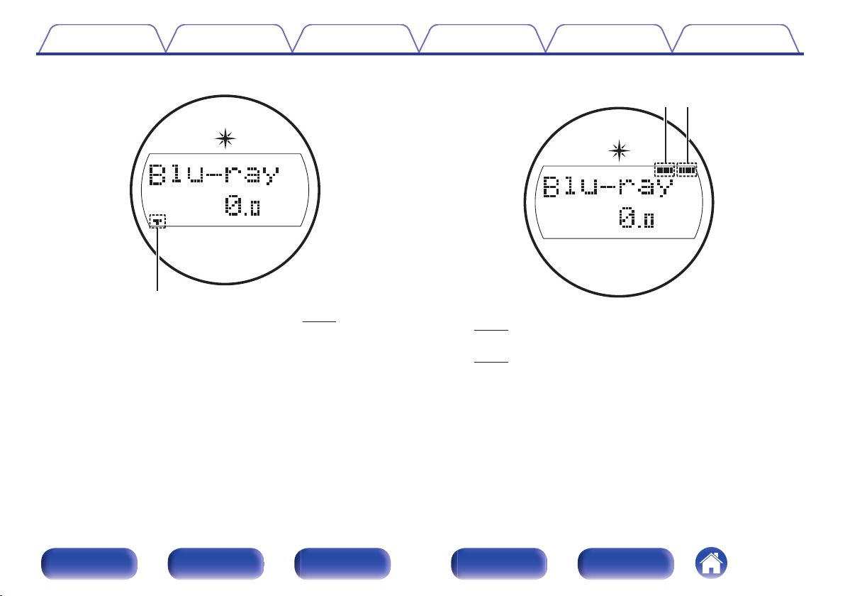
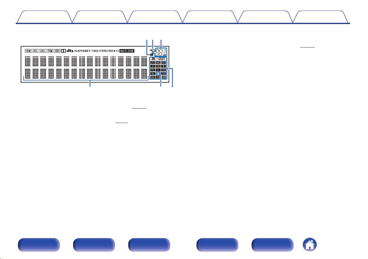
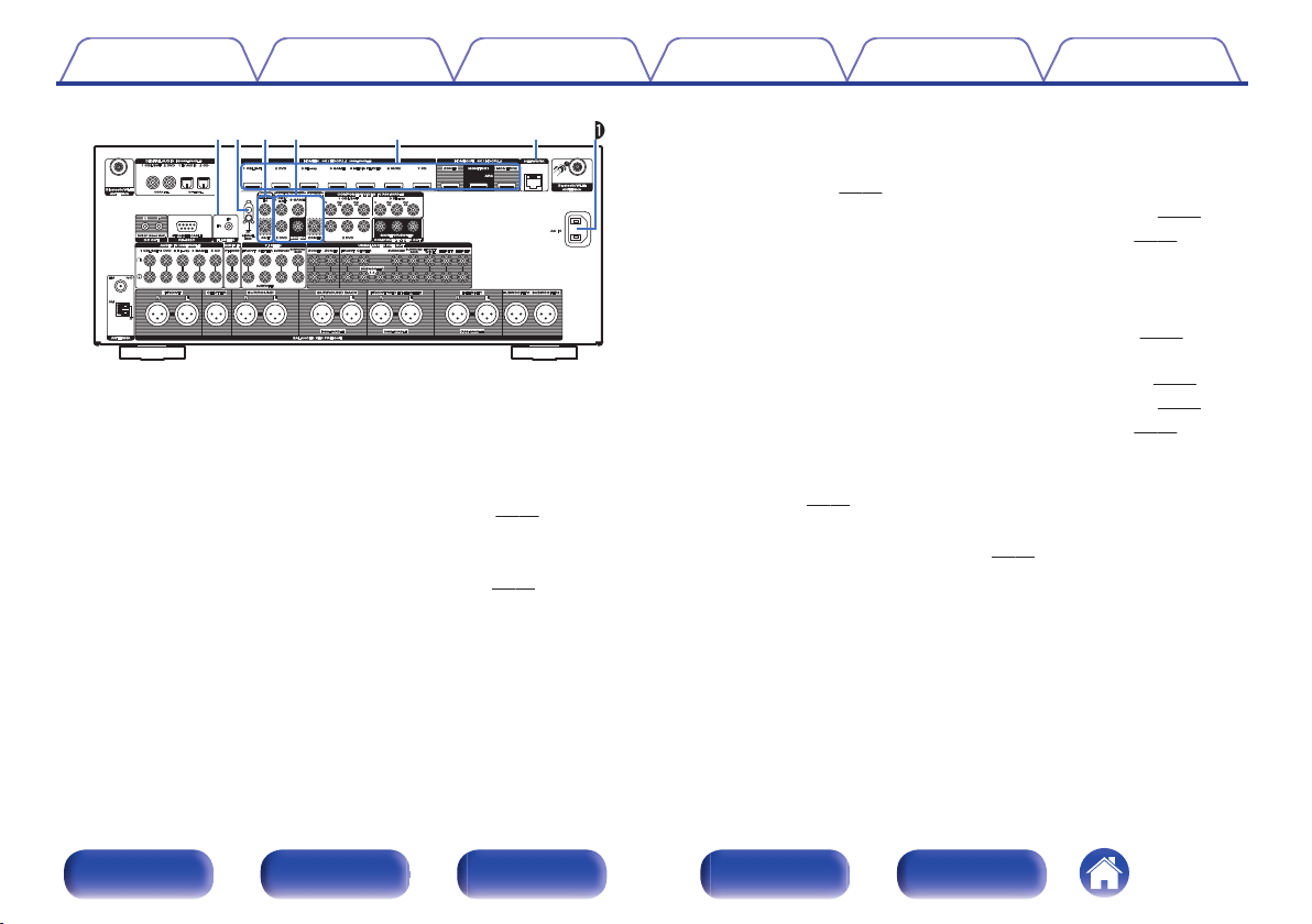
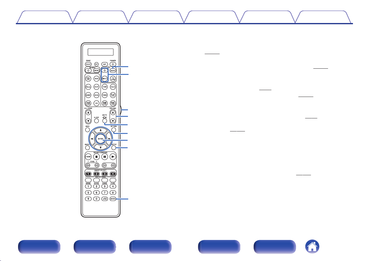
Front panelDisplayRear panelRemoteIndex
AirPlay function130
Playing songs from your iPhone, iPod touch or iPad131
Playing iTunes music with this unit131
Selecting multiple speakers (devices)132
Perform iTunes playback operations with the remote control unit
of this unit132
Spotify Connect function133
Playing Spotify music with this unit133
Convenience functions134
Performing repeat playback135
Performing random playback135
Registering to Favorites136
Playing back content added to the “Save to Favorites”136
Deleting content added to favorites137
Searching content with keywords (Text Search)137
Playing back music and a favorite picture at the same time
(Slideshow)138
Setting the Slideshow Interval139
Adjusting the volume of each channel to match the input source
(Channel Level Adjust)140
Adjusting the tone (Tone)141
Displaying your desired video during audio playback (Video
Select)142
Adjusting the picture quality for your viewing environment (Picture
Mode)143
Playing the same music in all zones (All Zone Stereo)144
Selecting a sound mode145
Selecting a sound mode146
Direct playback147
Pure Direct playback147
Auto surround playback148
HDMI control function160
Setting procedure160
Smart Menu function161
Sleep timer function163
Using the sleep timer164
Smart select function165
Calling up the settings166
Changing the settings167
Web control function168
Controlling the unit from a web control168
Panel lock function170
Disabling all key button operations170
Disabling all button operations except VOLUME170
Canceling the Panel lock function171
Remote lock function172
Disabling the sensor function of the remote control unit172
Enabling the remote sensor function172
Switches light illumination on/off173
Playback in ZONE2/ZONE3 (Separate room)174
Connecting ZONE174
Playback in ZONE2/ZONE3177
ContentsConnectionsPlaybackSettingsTipsAppendix
4
Front panelDisplayRear panelRemoteIndex
Settings
Menu map179
Menu operations182
Inputting characters183
Using the keyboard screen184
Audio185
Dialog Level Adjust185
Subwoofer Level Adjust185
Surround Parameter186
M-DAX191
Audio Delay192
Volume192
Audyssey®193
Graphic EQ197
Video200
Picture Adjust200
HDMI Setup202
Output Settings208
Component Video Out212
On Screen Display212
TV Format213
Inputs214
Input Assign214
Source Rename216
Hide Sources217
Source Level217
Input Select218
Speakers219
Audyssey® Setup219
Procedure for speaker settings (Audyssey® Setup)221
Error messages227
Retrieving Audyssey® Setup settings229
Manual Setup230
Amp Assign230
Speaker Config.236
Distances242
Levels243
Crossovers244
Bass245
Front Speaker246
2ch Playback246
ContentsConnectionsPlaybackSettingsTipsAppendix
5
Front panelDisplayRear panelRemoteIndex
Network249
Information249
Connection249
Wi-Fi Setup250
Settings253
Network Control255
Friendly Name255
Diagnostics256
Maintenance Mode257
General258
Language258
ZONE2 Setup/ZONE3 Setup258
Zone Rename261
Smart Select Names261
Trigger Out 1/Trigger Out 2261
Auto Standby262
Front Display263
Firmware264
Information266
Usage Data267
Setup Lock268
Operating external devices with the remote control unit269
Registering preset codes270
Operating devices274
Checking registered preset codes277
Initializing registered preset codes277
Operating learning function278
Remembering remote control codes from other devices279
Delete saved remote control codes280
Setting the back light281
Disabling the backlight281
Turning the backlight on281
Specifying the zone used with the remote control unit282
ContentsConnectionsPlaybackSettingsTipsAppendix
6
Front panelDisplayRear panelRemoteIndex
Tips
Tips284
Troubleshooting286
Resetting factory settings304
Appendix
About HDMI305
Video conversion function308
Playing back a USB memory devices310
Playing back a Bluetooth device311
Playing back a file saved on a PC or NAS312
Playing back Internet Radio313
Personal memory plus function313
Last function memory313
Sound modes and channel output314
Sound modes and surround parameters316
Types of input signals, and corresponding sound modes320
Explanation of terms324
Trademark information334
Specifications337
Index342
License345
ContentsConnectionsPlaybackSettingsTipsAppendix
7
Front panelDisplayRear panelRemoteIndex
Upgrade
Upgrade (Auro-3D)
The text marked with this symbol that will enable after the upgrade of the Auro-3D.
You can experience the best performance of Auro-3D if you install Front Height and Surround Height in addition to standard 5.1-channel. The “Setup
Assistant” will lead you to this setting.
You can use Rear Height speakers from a Dolby Atmos speaker setup instead of Surround Height speakers for Auro-3D playback.
The AVR also can play Auro-3D using standard 5.1-channel and Front Height speakers. If you install any height speakers instead of Surround Height
speakers and Rear Height speakers, you can set the speaker configuration in setup menu.
Auro-3D (Europe only)
Features
High quality sound12
Connecting a power amp
Speaker installation37, 40
Layout including height speakers and top speakers44
Speaker configuration and “Amp Assign” settings51
Auro-3D 9.1/10.1-channel system65, 69
Selecting a sound mode
Description of sound mode types Auro-3D sound mode151
Sound mode that can be selected for each input signal158
Audio
Auro-Matic 3D Preset189
Auro-Matic 3D Strength189
Inputs
Decode Mode218
Manual Setup
Amp Assign232, 235
Speaker Config.241
Appendix
Sound modes and channel output315
Sound mode and surround parameters318
Types of input signals, and corresponding sound modes322
Explanation of terms325
Trademark information336
ContentsConnectionsPlaybackSettingsTipsAppendix
8
Front panelDisplayRear panelRemoteIndex
Thank you for purchasing this Marantz product.
To ensure proper operation, please read this owner’s manual carefully before using the product.
After reading this manual, be sure to keep it for future reference.
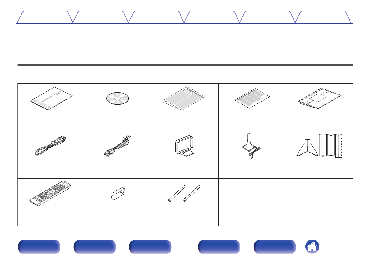
Accessories
Check that the following parts are supplied with the product.
.
Quick Start GuideCD-ROM
(Owner’s Manual)
Safety InstructionsNotes on radioCable labels
Power cordFM indoor antennaAM loop antennaSound calibration
microphone
(ACM1HB)
Sound calibration
microphone stand
Remote control unit
(RC027SR)
R03/AAA batteriesExternal antennas for
Bluetooth/wireless
connectivity
ContentsConnectionsPlaybackSettingsTipsAppendix
9
Front panelDisplayRear panelRemoteIndex
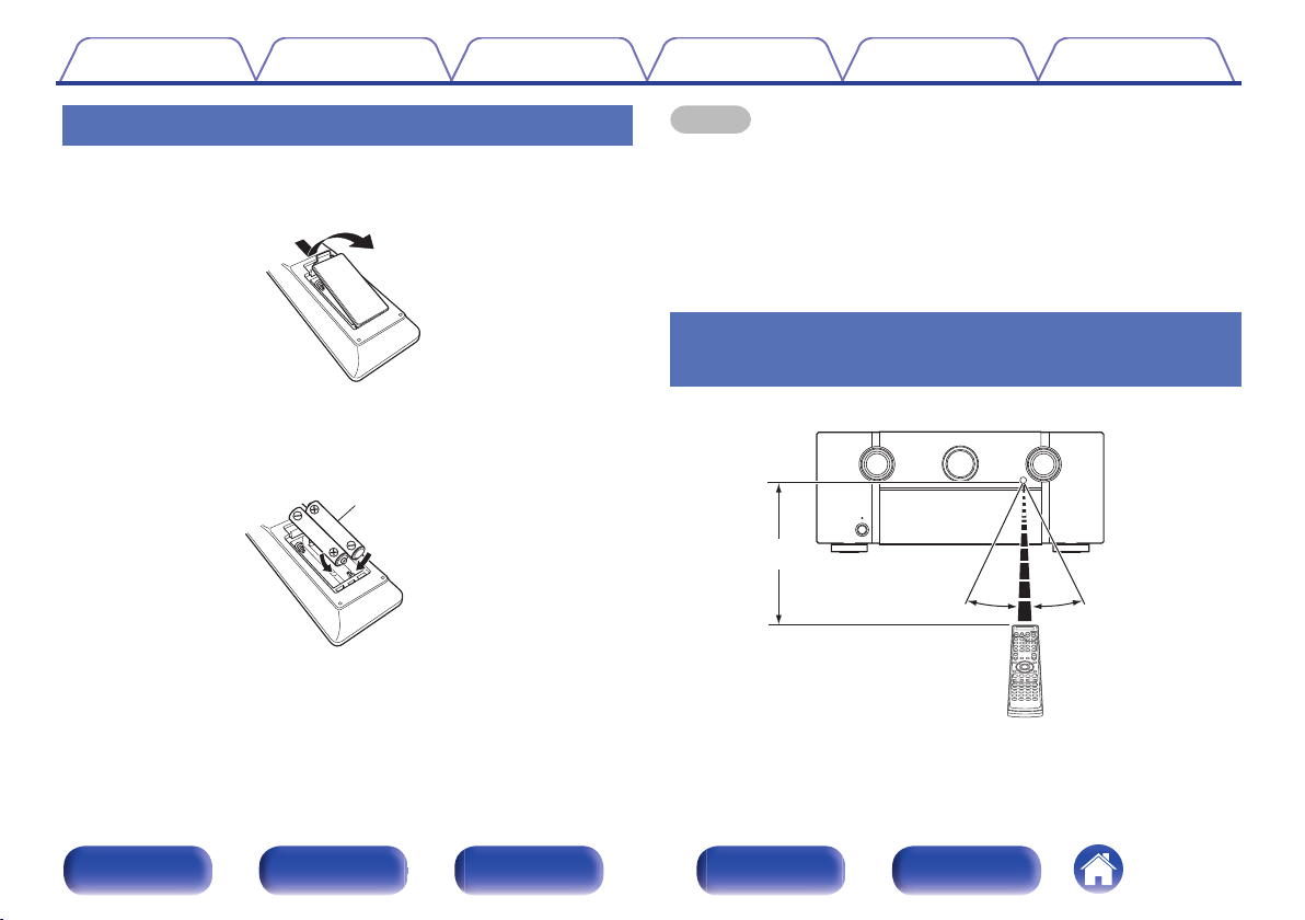
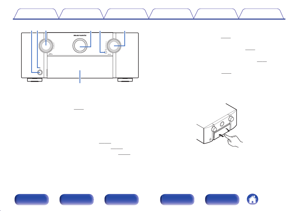
Inserting the batteries
1Remove the rear lid in the direction of the arrow and
remove it.
.
2Insert two batteries correctly into the battery
compartment as indicated.
.
R03/AAA batteries
3Put the rear cover back on.
NOTE
0To prevent damage or leakage of battery fluid:
0Do not use a new battery together with an old one.
0Do not use two different types of batteries.
0Remove the batteries from the remote control unit if it will not be in use for long
periods.
0If the battery fluid should leak, carefully wipe the fluid off the inside of the battery
compartment and insert new batteries.
Operating range of the remote control
unit
Point the remote control unit at the remote sensor when operating it.
.
30°30°
Approx. 7 m
ContentsConnectionsPlaybackSettingsTipsAppendix
10
Front panelDisplayRear panelRemoteIndex
Features
High quality sound
0Current feedback amplifier
This unit uses a high-speed current feedback amplifier circuit for its
preamplifier so that signals from a Blu-ray Disc player and other
equipment that support high-definition audio formats can be amplified
with high fidelity. The high-speed current feedback amplifier also
reproduces a natural sound space.
0Dolby Atmos (v p. 326)
This unit is equipped with a decoder that supports Dolby Atmos audio
format. The placement or movement of sound is accurately reproduced
by the addition of overhead speakers, enabling you to experience an
incredibly natural and realistic surround sound field.
0DTS:X
This unit is equipped with the DTS:X decoder technology. DTS:X
brings the home theater experience to new heights with its immersive
object based audio technology which removes the bounds of channels.
The flexibility of objects allows for sound to be scaled large or small
and moved around the room with greater accuracy than ever before
leading to a richer immersive audio experience.
0Audyssey DSX® (v p. 196)
This unit is equipped with Audyssey DSX® processor. By connecting
front height speakers to this unit and playing back with Audyssey DSX®
processing you can experience a more vertically expansive front
soundstage. By connecting two front wide speakers, you can
experience a wider and more expanded front soundstage.
0Audyssey LFC™ (Low Frequency Containment) (v p. 196)
Audyssey LFC™ solves the problem of low frequency sounds
disturbing people in neighboring rooms or apartments. Audyssey
LFC™ dynamically monitors the audio content and removes the low
frequencies that pass through walls, floors and ceilings. It then applies
psychoacoustic processing to restore the perception of low bass for
listeners in the room. The result is great sound that no longer disturbs
the neighbors.
0Discrete subwoofers and Audyssey Sub EQ HT™ (v p. 220)
The unit has two subwoofer output capability and can adjust the level
and delay for each subwoofer individually.
Audyssey Sub EQ HT™ makes the integration seamless by first
compensating for any level and delay differences between the two
subwoofers and then applying Audyssey MultEQ® XT32 to both
subwoofers together for improved deep bass response and detail.
ContentsConnectionsPlaybackSettingsTipsAppendix
11
Front panelDisplayRear panelRemoteIndex
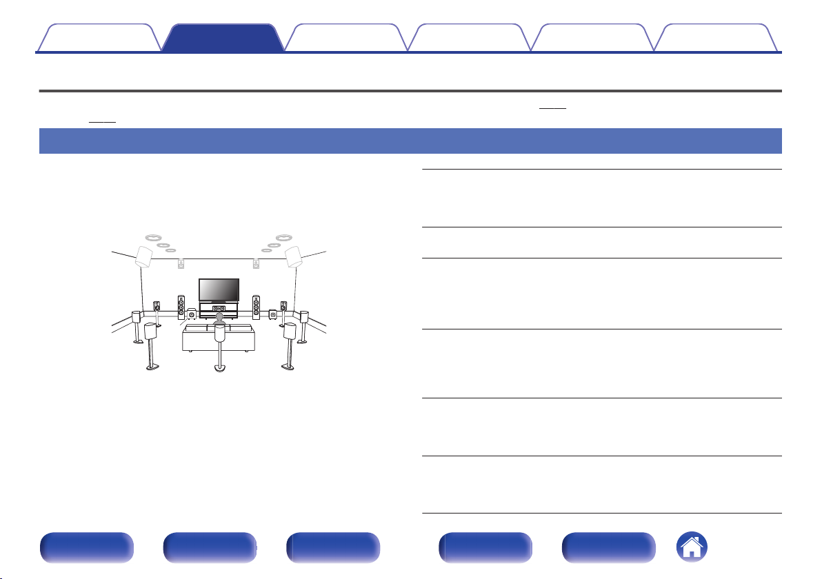
Upgrade (Auro-3D)
0Auro-3D
This unit is equipped with an Auro-3D decoder.
With Auro-3D, Front Height (FHL+FHR), Surround Height (SHL+SHR) and Top Surround (TS/optional) are added to a conventional 5.1-channel
system to achieve a natural and realistic sound field that is three-dimensional and fully immersive.
After performing the Auro-3D upgrade you will be able to fully enjoy Auro-3D playback if you properly place the speakers for Auro-3D.
2Auro-3D playback
.
FHLFHR
SHLSHR
TS
FLFR
SW
SLSR
C
2Dolby Atmos playback
.
FHLFHR
SHLSHR
TS
FLFR
SW
SLSR
C
0Auro-3D does not support a Dolby Atmos configuration using Top Front, Top Middle, Top Rear, or any Dolby Atmos Enabled speakers.
If you are using these speakers and want to take full advantage of the Auro-3D Upgrade, you need to relocate them to Front Height and Surround Height speaker locations as
shown above.
But it is possible to support both an Auro-3D and Dolby Atmos by adding Front Height and Rear Height speakers* to a 5.1 configuration.
zFor an optimum Auro-3D experience Surround Height speakers are strongly recommended.
ContentsConnectionsPlaybackSettingsTipsAppendix
12
Front panelDisplayRear panelRemoteIndex
High performance
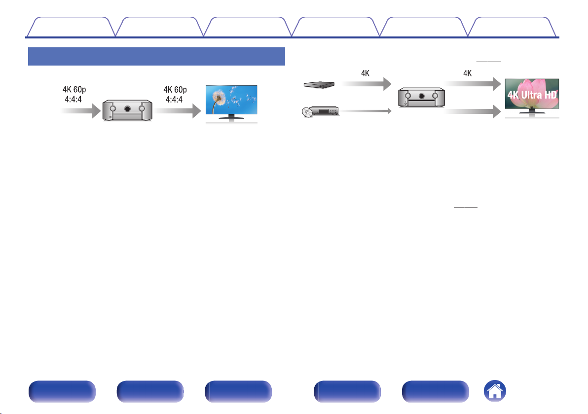
04K 60Hz input/output supported
.
When 4K Ultra HD (High Definition) is used, an input/output speed of 60
frames per second (60p) is achieved for video signals. When connected
to 4K Ultra HD and 60p video signal input compatible TV, you can enjoy
the sense of realism only available from high-definition images, even
when viewing fast-moving video.
This unit also supports image processing for 4K 60p, 4:4:4 and 24-bit
videos. By processing the video at the original resolution, this unit lets
you enjoy flawless, high-definition picture quality.
0HDCP 2.2
This unit is compatible with HDCP 2.2 copyright protection standard.
0Digital video processor upscales analog video signals (SD
resolution) to HD (720p/1080p) and 4K (v p. 210)
.
4K
Up scaling
Up to 1080p
This unit is equipped with a 4K video upscaling function that allows
analog video or SD (Standard Definition) video to be output via HDMI at
4K (3840 × 2160 pixels) resolution. This function enables the device to
be connected to a TV using a single HDMI cable, and produces high
definition images for any video source.
0Equipped with HDMI ZONE2 output (v p. 174)
The ZONE2 multi-room output includes an HDMI output that lets you
enjoy a different A/V source in that room, with another program playing
in the main room.
ContentsConnectionsPlaybackSettingsTipsAppendix
13
Front panelDisplayRear panelRemoteIndex
0HDMI connections enable connection to various digital AV
devices (8 inputs, 3 outputs)
.
83
OutIn
For connection to a broad range of digital sources, this unit features 8
HDMI inputs, including 1 on the front panel that lets you quickly and
conveniently connect a camcorder, game console or other HDMI-
equipped device. There are dual HDMI outputs for the main room, and a
third HDMI output for another room.
0The device is equipped with a AirPlay® function in addition to
network functions such as Internet radio etc. (v p. 130)
.
You can enjoy a wide variety of content, including listening to Internet
Radio, playing audio files stored on your PC, and displaying
photographs stored on your PC on our television.
This unit also supports Apple AirPlay which lets you stream your music
library from an iPhone®, iPad®, iPod touch® or iTunes®.
0Playback of DSD and FLAC files via USB and networks
This unit supports the playback of high resolution audio formats such as
DSD (2.8 MHz) and FLAC 192 kHz files. It provides high quality
playback of high resolution files.
ContentsConnectionsPlaybackSettingsTipsAppendix
14
Front panelDisplayRear panelRemoteIndex
0Wireless connection with Bluetooth devices can be carried out
easily (v p. 106)
.
You can enjoy music simply by connecting wirelessly with your
smartphone, tablet, PC, etc.
0Compatible with the “Marantz 2015 AVR Remote”z for performing
basic operations of the unit with an iPad, iPhone or Android™
devices (Google, Amazon Kindle Fire)
“Marantz 2015 AVR Remote” is application software that allows you to
perform basic operations with an iPad, iPhone, Android smartphone or
Android tablet such as turning the unit ON/OFF, controlling the volume,
and switching the source.
zDownload the appropriate “Marantz 2015 AVR Remote” for your iOS or Android
devices. This unit needs to be connected to the same LAN or Wi-Fi (wireless
LAN) network that the iPhone or iPod touch is connected to.
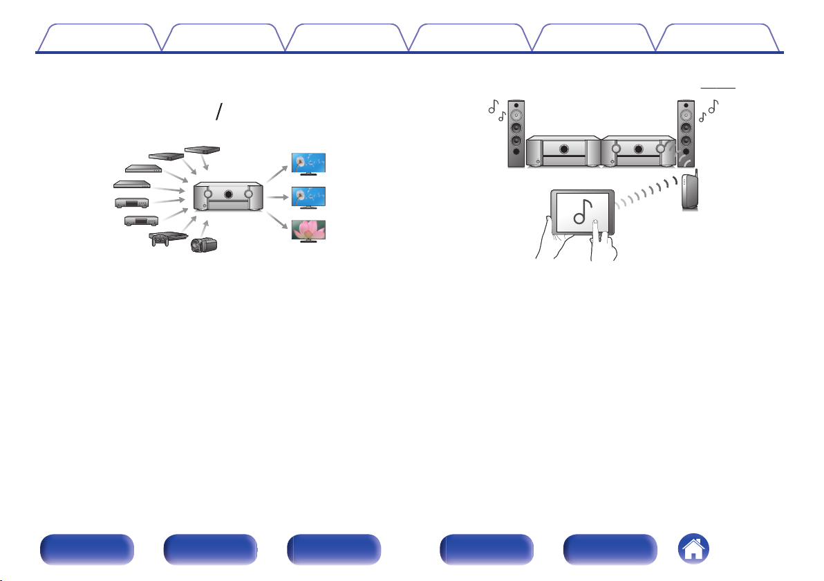
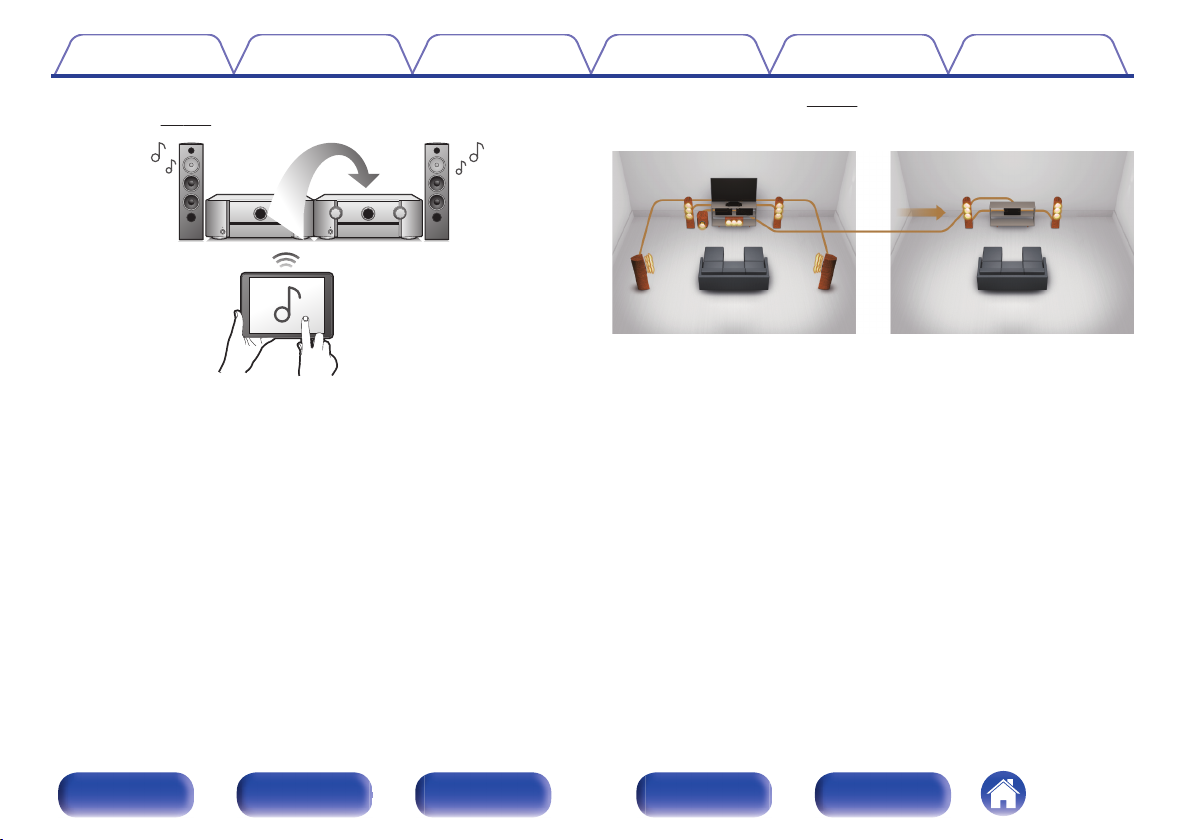
0Multi-Room audio (v p. 144)
.
【MAIN ZONE】【ZONE2】/【ZONE3】
You can select and play back the respective inputs in MAIN ZONE,
ZONE2 and ZONE3.
In addition, when the All Zone Stereo function is used, the music being
played back in MAIN ZONE can be enjoyed in all the zones at the same
time. This is useful when you want to let the BGM propagate throughout
the whole house.
0Energy-saving design
This unit is equipped with an auto-standby function that automatically
turns off the power supply when the unit is not in use. This helps reduce
Combination of 5.1-channel layout and front height/rear height
speakers.
.
FHLFHR
C
FLFR
SW
SLSR
RHLRHR
nCeiling speaker layout example
Combination of 5.1-channel layout and top front/top rear speakers.
.
TRR
TRL
TFR
TFL
C
FLFR
SW
SLSR
ContentsConnectionsPlaybackSettingsTipsAppendix
43
Front panelDisplayRear panelRemoteIndex
nDolby Atmos Enabled speaker layout example
Combination of 5.1-channel layout and front Dolby/surround Dolby
speakers.
.
C
FLFR
FDLFDR
SW
SLSR
SDLSDR
Upgrade (Auro-3D)
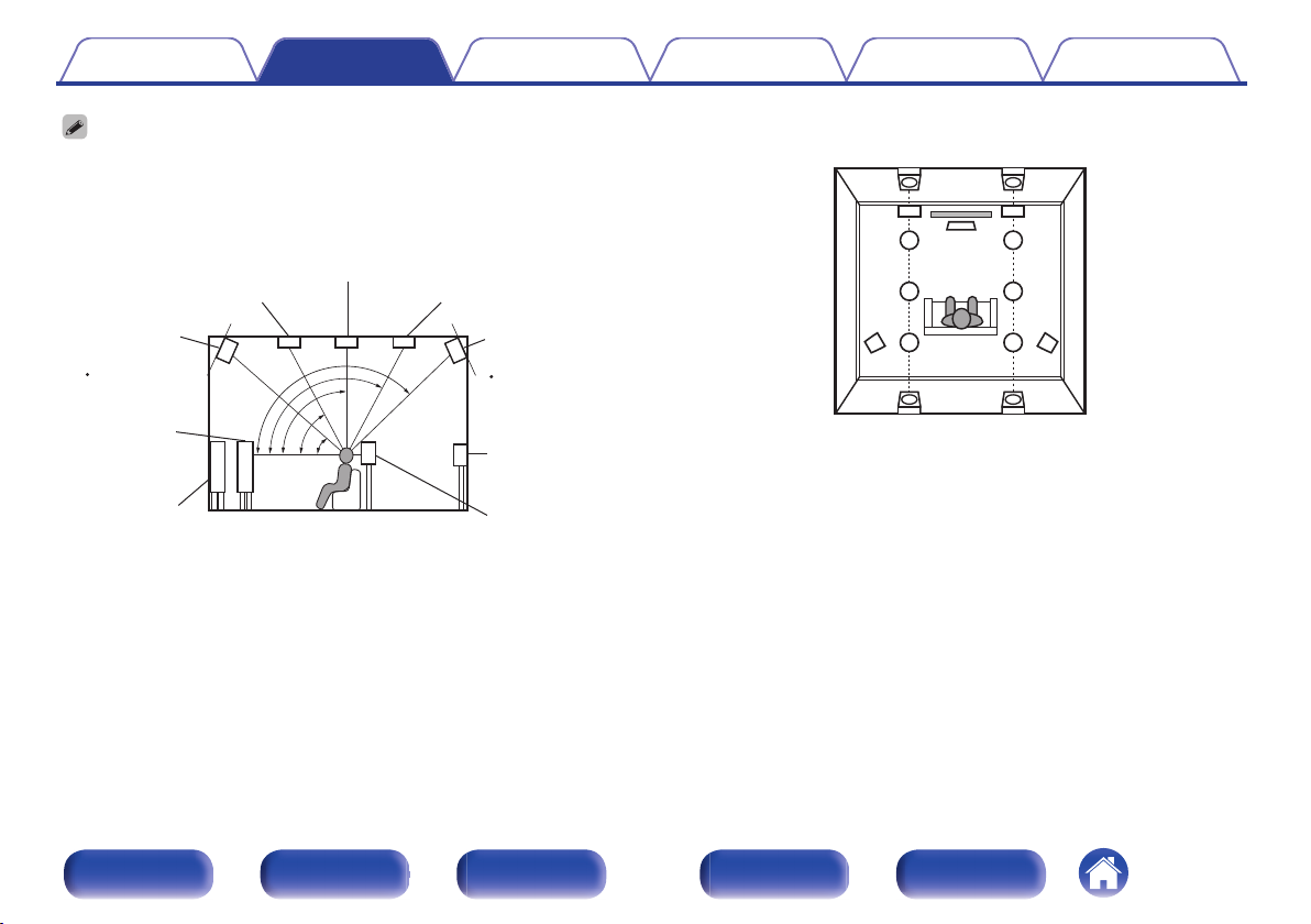
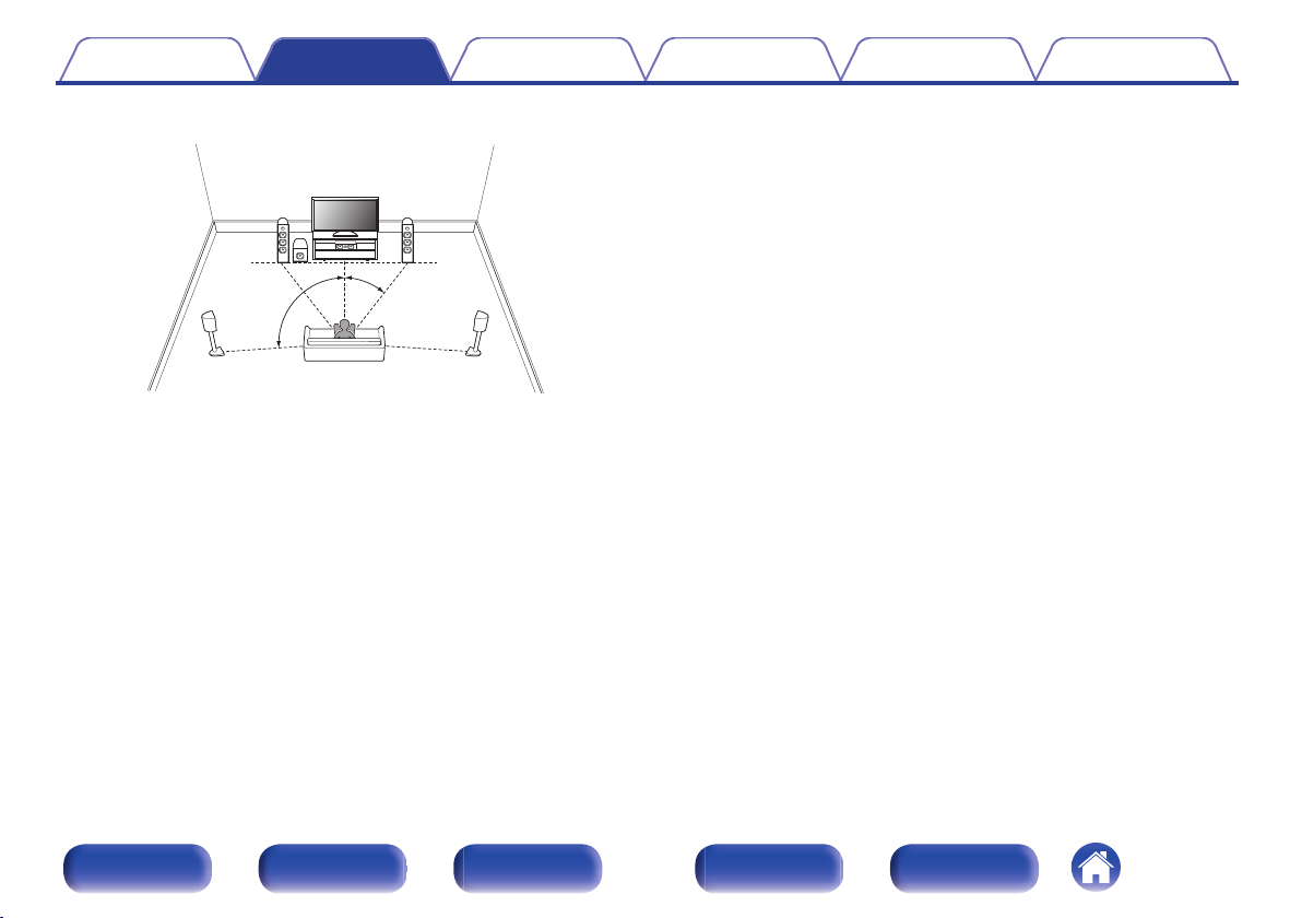
nAuro-3D layout example
Combination of 5.1-channel speakers with Front Height/Surround
Height/Top Surround speakers.
.
FHLFHR
SHLSHR
TS
FLFR
SW
SLSR
C
0For the best Auro-3D experience Surround Height speakers are recommended,
however you may substitute Rear Height speakers from a Dolby Atmos speaker
setup in place of Surround Height speakers.
ContentsConnectionsPlaybackSettingsTipsAppendix
44
Front panelDisplayRear panelRemoteIndex
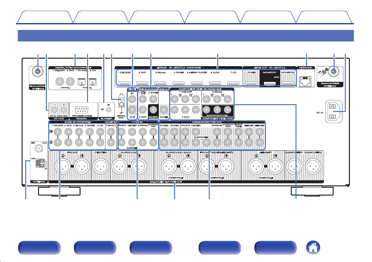
Connecting a power amp
0Connect a power amp (sold separately) to the PRE OUT connector of
this unit.
0This unit has UNBALANCED RCA PRE OUT connector and
BALANCED XLR PRE OUT connector. Connect to the correct
connector for your power amp. If your power amp has both connectors,
connect to either of them.
0Connect the speakers to the power amp.
0For details on speaker connections, see the Owner's Manual for the
power amp.
0This section shows how to make a 11.1-channel connection.
For how to make other speaker connections, see page 50.
GAV7702mkgBALANCED XLR PRE OUT connector PIN
arrangementH
.
12
3
AGND (Ground)
BHOT (+)
CCOLD (–)
The PIN arrangement in this device uses the European method.
In the USA method, B is COLD, and C is HOT.
When connecting a device that utilizes the USA type of PIN arrangement,
replace the B and C plugs on one side of the balanced cable.
NOTE
0Do not short the HOT and GND or COLD and GND for use.
0Disconnect this unit’s power plug from the power outlet before connecting the
speakers.
Also, turn off the power amp and subwoofer.
ContentsConnectionsPlaybackSettingsTipsAppendix
45
Front panelDisplayRear panelRemoteIndex
oExample of connections to Marantz MM8077 power amp
nConnecting the UNBALANCED RCA PRE OUT connector
.
CHANNEL1
(FL)
CHANNEL2
(FR)
CHANNEL3
(SL)
CHANNEL4
(SR)
CHANNEL7
(C)
CHANNEL1
(FL)
CHANNEL2
(FR)
CHANNEL3
(SL)
CHANNEL4
(SR)
CHANNEL7
(C)
CHANNEL5
(SBL)
CHANNEL6
(SBR)
CHANNEL5
(SBL)
CHANNEL6
(SBR)
CHANNEL7
(C)
CHANNEL7
(C)
CHANNEL1
(FL)
CHANNEL2
(FR)
CHANNEL3
(SL)
CHANNEL4
(SR)
CHANNEL1
(FL)
CHANNEL2
(FR)
CHANNEL3
(SL)
CHANNEL4
(SR)
CHANNEL5
(SBL)
CHANNEL6
(SBR)
CHANNEL5
(SBL)
CHANNEL6
(SBR)
SWSRSLFRFLC
BALANCED
BALANCED
UNBALANCED
UNBALANCED
FWRFWLFHRFHL
SBLSBR
【MM8077 】
ContentsConnectionsPlaybackSettingsTipsAppendix
46
Front panelDisplayRear panelRemoteIndex
nConnecting the BALANCED XLR PRE OUT connector
.
CHANNEL1
(FL)
CHANNEL2
(FR)
CHANNEL3
(SL)
CHANNEL4
(SR)
CHANNEL7
(C)
CHANNEL1
(FL)
CHANNEL2
(FR)
CHANNEL3
(SL)
CHANNEL4
(SR)
CHANNEL7
(C)
CHANNEL5
(SBL)
CHANNEL6
(SBR)
CHANNEL5
(SBL)
CHANNEL6
(SBR)
CHANNEL7
(C)
CHANNEL7
(C)
CHANNEL1
(FL)
CHANNEL2
(FR)
CHANNEL3
(SL)
CHANNEL4
(SR)
CHANNEL1
(FL)
CHANNEL2
(FR)
CHANNEL3
(SL)
CHANNEL4
(SR)
CHANNEL5
(SBL)
CHANNEL6
(SBR)
CHANNEL5
(SBL)
CHANNEL6
(SBR)
SRSLFRFLC
BALANCED
BALANCED
UNBALANCED
UNBALANCED
FWRFWLFHRFHL
SWSBLSBR
【MM8077 】
ContentsConnectionsPlaybackSettingsTipsAppendix
47
Front panelDisplayRear panelRemoteIndex
oAbout the cable labels (supplied) for channel
identification
Attach the cable label corresponding to each speaker to each speaker
cable.
This makes it easier to connect the speakers to the power amp.
ChannelColor
FRONT LWhite
FRONT RRed
CENTERGreen
SURROUND LLight blue
SURROUND RBlue
SURROUND BACK LBeige
SURROUND BACK RBrown
FRONT WIDE LLight Yellow
FRONT WIDE RYellow
FRONT HEIGHT LLight Yellow
FRONT HEIGHT RYellow
TOP FRONT LLight Yellow
TOP FRONT RYellow
TOP MIDDLE LLight Yellow
TOP MIDDLE RYellow
TOP REAR LLight Yellow
TOP REAR RYellow
REAR HEIGHT LLight Yellow
REAR HEIGHT RYellow
FRONT DOLBY LLight Yellow
FRONT DOLBY RYellow
SURROUND DOLBY LLight Yellow
SURROUND DOLBY RYellow
BACK DOLBY LLight Yellow
BACK DOLBY RYellow
SUBWOOFERBlack
ContentsConnectionsPlaybackSettingsTipsAppendix
48
Front panelDisplayRear panelRemoteIndex
Refer to the table and attach the label to each speaker cable.
GHow to attach the cable labelsH
.
Power amp
Speaker
ContentsConnectionsPlaybackSettingsTipsAppendix
49
Front panelDisplayRear panelRemoteIndex
Speaker configuration and “Amp Assign” settings
This system configuration plays back 11-channels. You can create speaker systems such as a bi-amp connection by changing the “Amp Assign” settings.
Perform “Amp Assign” settings to suit the number of rooms and speaker configuration to be installed. (v p. 230)
Playback speaker in MAIN ZONE“Amp Assign” settingsConnection page
5.1-channel playback11.1ch (Default)52
7.1-channel playback11.1ch (Default)53
9.1-channel playback11.1ch (Default)58
11.1-channel playback11.1ch (Default)66
9.1-channel playback (bi-amp connection of front speakers)9.1ch (Bi-Amp)73
9.1-channel playback + second pair of front speakers9.1ch + Front B74
The sound mode that can be selected varies according to the speaker configuration. See “Relationship between sound modes and channel output”
(v p. 314) for the sound modes that are supported.
The following pages provide basic connection examples.
ContentsConnectionsPlaybackSettingsTipsAppendix
50
Front panelDisplayRear panelRemoteIndex
Upgrade (Auro-3D)
Refer to the example connection for “Example connection for the Auro-3D
9.1-channel system” (v p. 65) when playing Auro-3D with a 9.1-
channel system using the basic 5.1-channel system and the front height
and surround height speakers.
Also refer to the connection example for “Example connection for the
Auro-3D 10.1-channel system” (v p. 69) when playing Auro-3D with a
10.1 channel system by adding the top surround speaker.
0In addition to the connections described in p.52 - 74, this unit allows for various
speaker connections with the “Amp Assign” setting.
Also refer to the menu screen in “View Terminal Config.” on the “Amp Assign”
setting screen, which shows how to make connections in your environment.
.
SUBWOOFER
F.HEIGHTF.WIDESURR.BACKSURROUNDCENTERFRONT
12
Back
Speakers/Amp Assign
RCA
Assign Mode11.1ch
XLR
FRONTSURROUNDCENTERSURR.BACKF.WIDEF.HEIGHT
12
SUBWOOFER
ContentsConnectionsPlaybackSettingsTipsAppendix
51
Front panelDisplayRear panelRemoteIndex
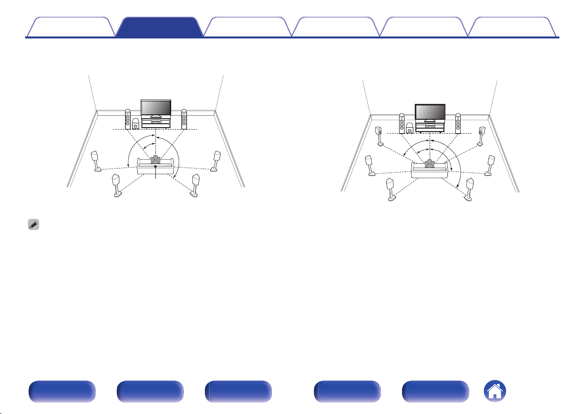
oStandard configuration and connection
Up to 11.2-channels can be connected by using either UNBALANCED
RCA connectors or BALANCED XLR connectors.
When using UNBALANCED RCA connectors for connection, set the
input change switch to “UNBALANCED” on MM8077.
When using BALANCED XLR connectors for connection, set the input
change switch to “BALANCED” on MM8077.
This example explains how to make a connection when using
UNBALANCED RCA connectors.
n5.1-channel playback
This serves as a basic 5.1-channel surround system.
.
FL
SWC
SL
FR
SR
.
CHANNEL5
(SBL)
CHANNEL6
(SBR)
CHANNEL1
(FL)
CHANNEL2
(FR)
CHANNEL3
(SL)
CHANNEL4
(SR)
CHANNEL7
(C)
CHANNEL1
(FL)
CHANNEL2
(FR)
CHANNEL3
(SL)
CHANNEL4
(SR)
CHANNEL7
(C)
CHANNEL5
(SBL)
CHANNEL6
(SBR)
BALANCEDBALANCED
UNBALANCEDUNBALANCED
SWSRSLFRFLC
【MM8077 】
ContentsConnectionsPlaybackSettingsTipsAppendix
52
Front panelDisplayRear panelRemoteIndex
o7.1-channel playback
nExample connections when using surround back speakers
This 7.1-channel surround system is the same as a basic 5.1-channel system but with surround back speakers.
.
FL
SWC
SL
FR
SR
SBLSBR
0Set “Floor” - “Layout” to “5ch & SB” in the menu when connecting in this
configuration. (v p. 231)
.
CHANNEL1
(FL)
CHANNEL2
(FR)
CHANNEL3
(SL)
CHANNEL4
(SR)
CHANNEL7
(C)
CHANNEL1
(FL)
CHANNEL2
(FR)
CHANNEL3
(SL)
CHANNEL4
(SR)
CHANNEL7
(C)
CHANNEL5
(SBL)
CHANNEL6
(SBR)
CHANNEL5
(SBL)
CHANNEL6
(SBR)
BALANCED
BALANCED
UNBALANCED
UNBALANCED
SWSRSLFRFLCSBLSBR
【MM8077 】
0When using a single surround back speaker, connect it to the SURROUND BACK
L terminal.
ContentsConnectionsPlaybackSettingsTipsAppendix
53
Front panelDisplayRear panelRemoteIndex
nExample connections when using front wide speakers
This 7.1-channel surround system is the same as a basic 5.1-channel system but with front wide speakers.
.
FL
SWC
SL
FR
SR
FWLFWR
.
CHANNEL1
(FL)
CHANNEL2
(FR)
CHANNEL3
(SL)
CHANNEL4
(SR)
CHANNEL7
(C)
CHANNEL1
(FL)
CHANNEL2
(FR)
CHANNEL3
(SL)
CHANNEL4
(SR)
CHANNEL7
(C)
CHANNEL5
(SBL)
CHANNEL6
(SBR)
CHANNEL5
(SBL)
CHANNEL6
(SBR)
BALANCED
BALANCED
UNBALANCED
UNBALANCED
SWSRSLFRFLCFWLFWR
【MM8077 】
0Set “Floor” - “Layout” to “5ch & FW” in the menu when connecting in this configuration. (v p. 231)
ContentsConnectionsPlaybackSettingsTipsAppendix
54
Front panelDisplayRear panelRemoteIndex
nExample connections when using ceiling speakers
This 7.1-channel surround system is the same as a basic 5.1-channel system but with ceiling speakers.
.
C
FLFR
SW
SLSR
TMLTMR
.
CHANNEL1
(FL)
CHANNEL2
(FR)
CHANNEL3
(SL)
CHANNEL4
(SR)
CHANNEL7
(C)
CHANNEL1
(FL)
CHANNEL2
(FR)
CHANNEL3
(SL)
CHANNEL4
(SR)
CHANNEL7
(C)
CHANNEL5
(SBL)
CHANNEL6
(SBR)
CHANNEL5
(SBL)
CHANNEL6
(SBR)
BALANCED
BALANCED
UNBALANCED
UNBALANCED
SWSRSLFRFLCTMLTMR
【MM8077 】
0Set “Floor” - “Layout” to “5ch” and “Height Sp” to “2ch” in the menu when connecting in this configuration. (v p. 231)
0The top front or top rear speakers can be connected instead of the top middle speakers. In this case, set the ceiling speakers to be connected under “Height” - “Layout” in the
menu. (v p. 233)
ContentsConnectionsPlaybackSettingsTipsAppendix
55
Front panelDisplayRear panelRemoteIndex
nExample connections when using height speakers
.
FL
SWC
SL
FR
SR
FHLFHR
.
CHANNEL1
(FL)
CHANNEL2
(FR)
CHANNEL3
(SL)
CHANNEL4
(SR)
CHANNEL7
(C)
CHANNEL1
(FL)
CHANNEL2
(FR)
CHANNEL3
(SL)
CHANNEL4
(SR)
CHANNEL7
(C)
CHANNEL5
(SBL)
CHANNEL6
(SBR)
CHANNEL5
(SBL)
CHANNEL6
(SBR)
BALANCED
BALANCED
UNBALANCED
UNBALANCED
SWSRSLFRFLCFHLFHR
【MM8077 】
0Set “Floor” - “Layout” to “5ch” and “Height Sp” to “2ch” in the menu when connecting in this configuration. (v p. 231)
0The rear height speakers can be connected instead of the front height speakers. In this case, set the height speakers to be connected under “Height” - “Layout” in the menu.
(v p. 233)
ContentsConnectionsPlaybackSettingsTipsAppendix
56
Front panelDisplayRear panelRemoteIndex
nExample connections when using Dolby Atmos Enabled speakers
This 7.1-channel surround system is the same as a basic 5.1-channel system but with front Dolby speakers.
.
C
FLFR
SW
SLSR
FDLFDR
.
CHANNEL1
(FL)
CHANNEL2
(FR)
CHANNEL3
(SL)
CHANNEL4
(SR)
CHANNEL7
(C)
CHANNEL1
(FL)
CHANNEL2
(FR)
CHANNEL3
(SL)
CHANNEL4
(SR)
CHANNEL7
(C)
CHANNEL5
(SBL)
CHANNEL6
(SBR)
CHANNEL5
(SBL)
CHANNEL6
(SBR)
BALANCED
BALANCED
UNBALANCED
UNBALANCED
SWSRSLFRFLCFDLFDR
【MM8077 】
0Set “Floor” - “Layout” to “5ch” and “Dolby Sp” to “2ch” in the menu when connecting in this configuration. (v p. 231)
0The surround Dolby speakers can be connected instead of the front Dolby speakers. In this case, set the Dolby Atmos Enabled speakers to be connected under “Height” -
“Layout” in the menu. (v p. 233)
ContentsConnectionsPlaybackSettingsTipsAppendix
57
Front panelDisplayRear panelRemoteIndex
o9.1-channel playback
This system, which is based on a 5.1-channel system, plays back up to 9.1-channels at the same time.
nExample connection when using surround back and front wide speakers
.
FL
SWC
SL
FR
SR
FWLFWR
SBLSBR
.
CHANNEL1
(FL)
CHANNEL2
(FR)
CHANNEL3
(SL)
CHANNEL4
(SR)
CHANNEL7
(C)
CHANNEL1
(FL)
CHANNEL2
(FR)
CHANNEL3
(SL)
CHANNEL4
(SR)
CHANNEL7
(C)
CHANNEL5
(SBL)
CHANNEL6
(SBR)
CHANNEL5
(SBL)
CHANNEL6
(SBR)
CHANNEL7
(C)
CHANNEL7
(C)
CHANNEL1
(FL)
CHANNEL2
(FR)
CHANNEL3
(SL)
CHANNEL4
(SR)
CHANNEL1
(FL)
CHANNEL2
(FR)
CHANNEL3
(SL)
CHANNEL4
(SR)
CHANNEL5
(SBL)
CHANNEL6
(SBR)
CHANNEL5
(SBL)
CHANNEL6
(SBR)
SWSRSLFRFLC
BALANCED
BALANCED
UNBALANCED
UNBALANCED
FWLFWR
【MM8077 】
SBLSBR
0Set “Floor” - “Layout” to “5ch & SB & FW” in the menu when connecting in this configuration. (v p. 231)
ContentsConnectionsPlaybackSettingsTipsAppendix
58
Front panelDisplayRear panelRemoteIndex
nExample connection when using one set of ceiling speakers
.
C
FLFR
SBLSBR
SW
SLSR
TMLTMR
0Set “Height” - “Height Sp” to “2ch” in the menu when connecting in this
configuration. (v p. 232)
.
CHANNEL1
(FL)
CHANNEL2
(FR)
CHANNEL3
(SL)
CHANNEL4
(SR)
CHANNEL7
(C)
CHANNEL1
(FL)
CHANNEL2
(FR)
CHANNEL3
(SL)
CHANNEL4
(SR)
CHANNEL7
(C)
CHANNEL5
(SBL)
CHANNEL6
(SBR)
CHANNEL5
(SBL)
CHANNEL6
(SBR)
CHANNEL7
(C)
CHANNEL7
(C)
CHANNEL1
(FL)
CHANNEL2
(FR)
CHANNEL3
(SL)
CHANNEL4
(SR)
CHANNEL1
(FL)
CHANNEL2
(FR)
CHANNEL3
(SL)
CHANNEL4
(SR)
CHANNEL5
(SBL)
CHANNEL6
(SBR)
CHANNEL5
(SBL)
CHANNEL6
(SBR)
SWSRSLFRFLC
BALANCED
BALANCED
UNBALANCED
UNBALANCED
TMLTMR
【MM8077 】
SBLSBR
HEIGHT 1z
zThe top front or top rear speakers can be connected instead of the top middle
speakers. In this case, set the ceiling speakers to be connected under “Height” -
“Layout” in the menu. (v p. 233)
ContentsConnectionsPlaybackSettingsTipsAppendix
59
Front panelDisplayRear panelRemoteIndex
nExample connection when using two sets of ceiling speakers
.
C
FLFR
SW
SLSR
TRLTRR
TFLTFR
0Set “Floor” - “Layout” to “5ch” or set “5ch & SB” and “Height Sp” to “4ch” in the
menu when connecting in this configuration. (v p. 231)
.
CHANNEL1
(FL)
CHANNEL2
(FR)
CHANNEL3
(SL)
CHANNEL4
(SR)
CHANNEL7
(C)
CHANNEL1
(FL)
CHANNEL2
(FR)
CHANNEL3
(SL)
CHANNEL4
(SR)
CHANNEL7
(C)
CHANNEL5
(SBL)
CHANNEL6
(SBR)
CHANNEL5
(SBL)
CHANNEL6
(SBR)
CHANNEL7
(C)
CHANNEL7
(C)
CHANNEL1
(FL)
CHANNEL2
(FR)
CHANNEL3
(SL)
CHANNEL4
(SR)
CHANNEL1
(FL)
CHANNEL2
(FR)
CHANNEL3
(SL)
CHANNEL4
(SR)
CHANNEL5
(SBL)
CHANNEL6
(SBR)
CHANNEL5
(SBL)
CHANNEL6
(SBR)
SWSRSLFRFLC
BALANCED
BALANCED
UNBALANCED
UNBALANCED
TRLTRR
【MM8077 】
HEIGHT 2z
HEIGHT 1z
TFLTFR
zYou can change the combination of the HEIGHT1 and HEIGHT2 channels in the
settings. (v p. 70)
ContentsConnectionsPlaybackSettingsTipsAppendix
60
Front panelDisplayRear panelRemoteIndex
nExample connection when using one set of height speakers
.
C
FLFR
SBLSBR
SW
SLSR
FHLFHR
0Set “Height” - “Height Sp” to “2ch” in the menu when connecting in this
configuration. (v p. 232)
.
CHANNEL1
(FL)
CHANNEL2
(FR)
CHANNEL3
(SL)
CHANNEL4
(SR)
CHANNEL7
(C)
CHANNEL1
(FL)
CHANNEL2
(FR)
CHANNEL3
(SL)
CHANNEL4
(SR)
CHANNEL7
(C)
CHANNEL5
(SBL)
CHANNEL6
(SBR)
CHANNEL5
(SBL)
CHANNEL6
(SBR)
CHANNEL7
(C)
CHANNEL7
(C)
CHANNEL1
(FL)
CHANNEL2
(FR)
CHANNEL3
(SL)
CHANNEL4
(SR)
CHANNEL1
(FL)
CHANNEL2
(FR)
CHANNEL3
(SL)
CHANNEL4
(SR)
CHANNEL5
(SBL)
CHANNEL6
(SBR)
CHANNEL5
(SBL)
CHANNEL6
(SBR)
SWSRSLFRFLC
BALANCED
BALANCED
UNBALANCED
UNBALANCED
FHLFHR
【MM8077 】
SBLSBR
HEIGHT 1z
zThe rear height speakers can be connected instead of the front height speakers.
In this case, set the height speakers to be connected under “Height” - “Layout” in
the menu. (v p. 233)
ContentsConnectionsPlaybackSettingsTipsAppendix
61
Front panelDisplayRear panelRemoteIndex
nExample connection when using two sets of height speakers
.
C
FLFR
SW
SLSR
FHLFHR
RHLRHR
0Set “Floor” - “Layout” to “5ch” or set “5ch & SB” and “Height Sp” to “4ch” in the
menu when connecting in this configuration. (v p. 231)
.
CHANNEL1
(FL)
CHANNEL2
(FR)
CHANNEL3
(SL)
CHANNEL4
(SR)
CHANNEL7
(C)
CHANNEL1
(FL)
CHANNEL2
(FR)
CHANNEL3
(SL)
CHANNEL4
(SR)
CHANNEL7
(C)
CHANNEL5
(SBL)
CHANNEL6
(SBR)
CHANNEL5
(SBL)
CHANNEL6
(SBR)
CHANNEL7
(C)
CHANNEL7
(C)
CHANNEL1
(FL)
CHANNEL2
(FR)
CHANNEL3
(SL)
CHANNEL4
(SR)
CHANNEL1
(FL)
CHANNEL2
(FR)
CHANNEL3
(SL)
CHANNEL4
(SR)
CHANNEL5
(SBL)
CHANNEL6
(SBR)
CHANNEL5
(SBL)
CHANNEL6
(SBR)
SWSRSLFRFLC
BALANCED
BALANCED
UNBALANCED
UNBALANCED
RHLRHR
【MM8077 】
HEIGHT 2z
HEIGHT 1z
FHLFHR
zYou can change the combination of the HEIGHT1 and HEIGHT2 channels in the
settings. (v p. 70)
ContentsConnectionsPlaybackSettingsTipsAppendix
62
Front panelDisplayRear panelRemoteIndex
nExample connection when using one set of Dolby Atmos Enabled speakers
.
C
SBLSBR
SW
SLSR
FLFR
FDLFDR
0Set “Height” - “Dolby Sp” to “2ch” in the menu when connecting in this
configuration. (v p. 232)
.
CHANNEL1
(FL)
CHANNEL2
(FR)
CHANNEL3
(SL)
CHANNEL4
(SR)
CHANNEL7
(C)
CHANNEL1
(FL)
CHANNEL2
(FR)
CHANNEL3
(SL)
CHANNEL4
(SR)
CHANNEL7
(C)
CHANNEL5
(SBL)
CHANNEL6
(SBR)
CHANNEL5
(SBL)
CHANNEL6
(SBR)
CHANNEL7
(C)
CHANNEL7
(C)
CHANNEL1
(FL)
CHANNEL2
(FR)
CHANNEL3
(SL)
CHANNEL4
(SR)
CHANNEL1
(FL)
CHANNEL2
(FR)
CHANNEL3
(SL)
CHANNEL4
(SR)
CHANNEL5
(SBL)
CHANNEL6
(SBR)
CHANNEL5
(SBL)
CHANNEL6
(SBR)
SWSRSLFRFLC
BALANCED
BALANCED
UNBALANCED
UNBALANCED
FDLFDR
【MM8077 】
SBLSBR
HEIGHT 1z
zThe surround Dolby speakers can be connected instead of the front Dolby
speakers. In this case, set the Dolby Atmos Enabled speakers to be connected
under “Height” - “Layout” in the menu. (v p. 233)
ContentsConnectionsPlaybackSettingsTipsAppendix
63
Front panelDisplayRear panelRemoteIndex
nExample connection when using two sets of Dolby Atmos Enabled speakers
.
C
SW
SLSR
FLFR
FDLFDR
SDLSDR
0Set “Floor” - “Layout” to “5ch” or set “5ch & SB” and “Dolby Sp” to “4ch” in the
menu when connecting in this configuration. (v p. 231)
.
CHANNEL1
(FL)
CHANNEL2
(FR)
CHANNEL3
(SL)
CHANNEL4
(SR)
CHANNEL7
(C)
CHANNEL1
(FL)
CHANNEL2
(FR)
CHANNEL3
(SL)
CHANNEL4
(SR)
CHANNEL7
(C)
CHANNEL5
(SBL)
CHANNEL6
(SBR)
CHANNEL5
(SBL)
CHANNEL6
(SBR)
CHANNEL7
(C)
CHANNEL7
(C)
CHANNEL1
(FL)
CHANNEL2
(FR)
CHANNEL3
(SL)
CHANNEL4
(SR)
CHANNEL1
(FL)
CHANNEL2
(FR)
CHANNEL3
(SL)
CHANNEL4
(SR)
CHANNEL5
(SBL)
CHANNEL6
(SBR)
CHANNEL5
(SBL)
CHANNEL6
(SBR)
SWSRSLFRFLC
BALANCED
BALANCED
UNBALANCED
UNBALANCED
SDLSDR
【MM8077 】
HEIGHT 2z
HEIGHT 1z
FDLFDR
zYou can change the combination of the HEIGHT1 and HEIGHT2 channels in the
settings. (v p. 70)
ContentsConnectionsPlaybackSettingsTipsAppendix
64
Front panelDisplayRear panelRemoteIndex
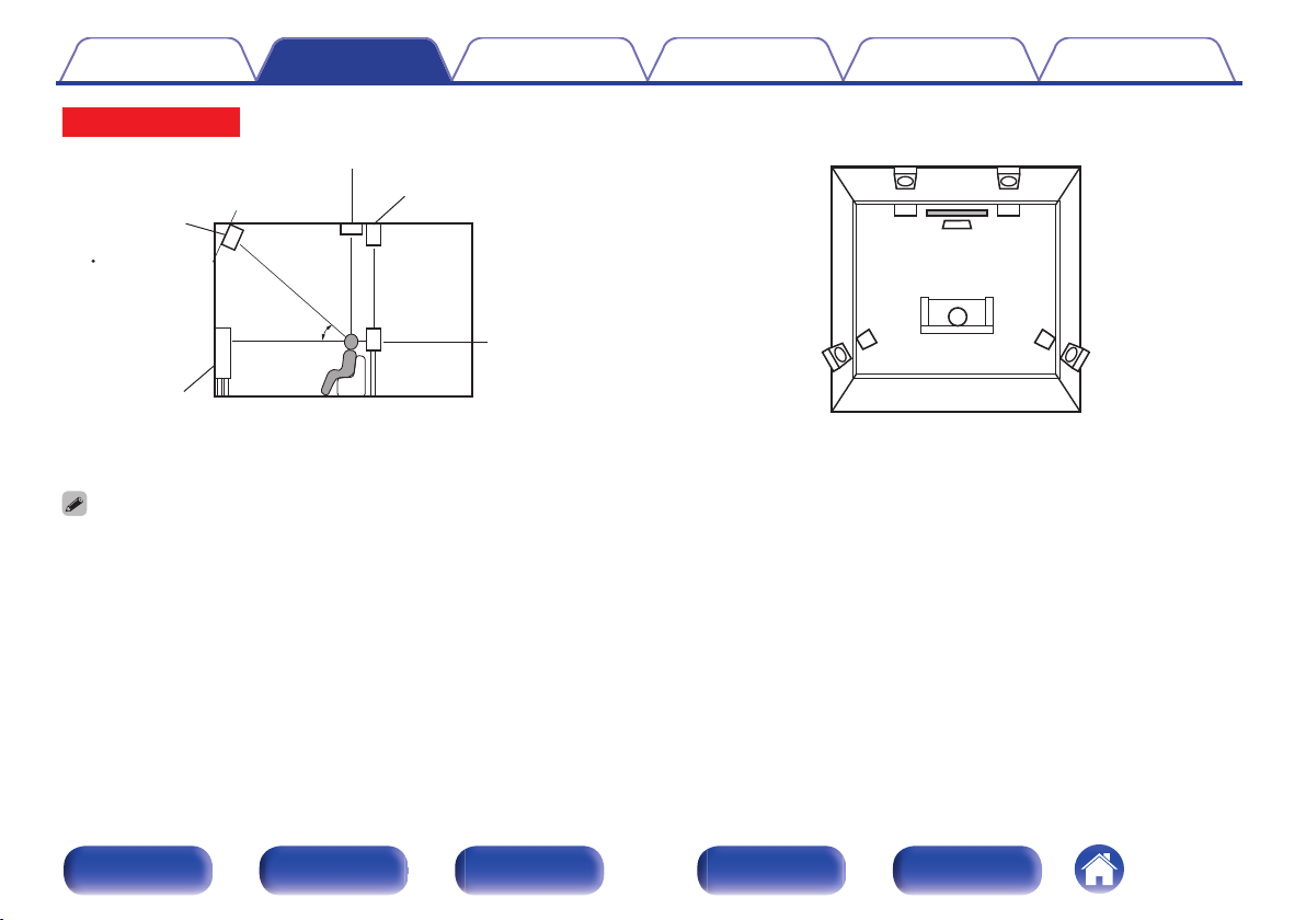
Upgrade (Auro-3D)
nExample connection for the Auro-3D 9.1-channel system
This speaker configuration is optimized for Auro-3D playback.
.
FLFR
SW
SLSR
C
FHLFHR
SHLSHR
0Set “Floor” - “Layout” to “5ch” or set “5ch & SB” and “Height Sp” to “4ch” in the
menu when connecting in this configuration. (v p. 232)
Next, set “Height” - “Layout” to “Front Height & Surr. Height”. (v p. 233)
.
CHANNEL1
(FL)
CHANNEL2
(FR)
CHANNEL3
(SL)
CHANNEL4
(SR)
CHANNEL7
(C)
CHANNEL1
(FL)
CHANNEL2
(FR)
CHANNEL3
(SL)
CHANNEL4
(SR)
CHANNEL7
(C)
CHANNEL5
(SBL)
CHANNEL6
(SBR)
CHANNEL5
(SBL)
CHANNEL6
(SBR)
CHANNEL7
(C)
CHANNEL7
(C)
CHANNEL1
(FL)
CHANNEL2
(FR)
CHANNEL3
(SL)
CHANNEL4
(SR)
CHANNEL1
(FL)
CHANNEL2
(FR)
CHANNEL3
(SL)
CHANNEL4
(SR)
CHANNEL5
(SBL)
CHANNEL6
(SBR)
CHANNEL5
(SBL)
CHANNEL6
(SBR)
SWSRSLFRFLC
BALANCED
BALANCED
UNBALANCED
UNBALANCED
SHLSHR
【MM8077 】
HEIGHT 2z
HEIGHT 1z
FHLFHR
zYou can change the combination of the HEIGHT1 and HEIGHT2 channels in the
settings. (v p. 72)
ContentsConnectionsPlaybackSettingsTipsAppendix
65
Front panelDisplayRear panelRemoteIndex
o11.1-channel playback
This system, which is based on a 5.1-channel system, plays back up to
11.1-channels at the same time.
You can connect speakers for up to 13-channels for MAIN ZONE.
When you connect speakers for 12 or more channels, the output
speakers automatically switch according to the input signal and sound
mode.
nExample connection when using two sets of ceiling
speakers
.
C
FLFR
SBLSBR
SW
FWLFWR
SLSR
TRLTRR
TFLTFR
0Set “Height” - “Height Sp” to “4ch” in the menu when connecting in this
configuration. (v p. 232)
.
CHANNEL7
(C)
CHANNEL7
(C)
CHANNEL1
(FL)
CHANNEL2
(FR)
CHANNEL3
(SL)
CHANNEL4
(SR)
CHANNEL1
(FL)
CHANNEL2
(FR)
CHANNEL3
(SL)
CHANNEL4
(SR)
CHANNEL5
(SBL)
CHANNEL6
(SBR)
CHANNEL5
(SBL)
CHANNEL6
(SBR)
CHANNEL1
(FL)
CHANNEL2
(FR)
CHANNEL3
(SL)
CHANNEL4
(SR)
CHANNEL7
(C)
CHANNEL1
(FL)
CHANNEL2
(FR)
CHANNEL3
(SL)
CHANNEL4
(SR)
CHANNEL7
(C)
CHANNEL5
(SBL)
CHANNEL6
(SBR)
CHANNEL5
(SBL)
CHANNEL6
(SBR)
BALANCED
BALANCED
UNBALANCED
UNBALANCED
SWSRSLFRFLCSBLSBRFWRFWL
HEIGHT 2zHEIGHT 1z
BALANCED
BALANCED
UNBALANCED
UNBALANCED
TRLTRRTFLTFR
【MM8077 】
zYou can change the combination of the HEIGHT1 and HEIGHT2 channels in the
settings. (v p. 70)
ContentsConnectionsPlaybackSettingsTipsAppendix
66
Front panelDisplayRear panelRemoteIndex
nExample connection when using two sets of height speakers
.
C
FLFR
SBLSBR
SW
FWLFWR
SLSR
FHLFHR
RHLRHR
0Set “Height” - “Height Sp” to “4ch” in the menu when connecting in this
configuration. (v p. 232)
.
CHANNEL7
(C)
CHANNEL7
(C)
CHANNEL1
(FL)
CHANNEL2
(FR)
CHANNEL3
(SL)
CHANNEL4
(SR)
CHANNEL1
(FL)
CHANNEL2
(FR)
CHANNEL3
(SL)
CHANNEL4
(SR)
CHANNEL5
(SBL)
CHANNEL6
(SBR)
CHANNEL5
(SBL)
CHANNEL6
(SBR)
CHANNEL1
(FL)
CHANNEL2
(FR)
CHANNEL3
(SL)
CHANNEL4
(SR)
CHANNEL7
(C)
CHANNEL1
(FL)
CHANNEL2
(FR)
CHANNEL3
(SL)
CHANNEL4
(SR)
CHANNEL7
(C)
CHANNEL5
(SBL)
CHANNEL6
(SBR)
CHANNEL5
(SBL)
CHANNEL6
(SBR)
BALANCED
BALANCED
UNBALANCED
UNBALANCED
SWSRSLFRFLCSBLSBRFWRFWL
HEIGHT 2zHEIGHT 1z
BALANCED
BALANCED
UNBALANCED
UNBALANCED
RHLRHRFHLFHR
【MM8077 】
zYou can change the combination of the HEIGHT1 and HEIGHT2 channels in the
settings. (v p. 70)
ContentsConnectionsPlaybackSettingsTipsAppendix
67
Front panelDisplayRear panelRemoteIndex
nExample connection when using two sets of Dolby Atmos Enabled speakers
.
C
SBLSBR
SW
FWLFWR
SLSR
FLFR
FDLFDR
SDLSDR
0Set “Height” - “Dolby Sp” to “4ch” in the menu when connecting in this
configuration. (v p. 232)
.
CHANNEL7
(C)
CHANNEL7
(C)
CHANNEL1
(FL)
CHANNEL2
(FR)
CHANNEL3
(SL)
CHANNEL4
(SR)
CHANNEL1
(FL)
CHANNEL2
(FR)
CHANNEL3
(SL)
CHANNEL4
(SR)
CHANNEL5
(SBL)
CHANNEL6
(SBR)
CHANNEL5
(SBL)
CHANNEL6
(SBR)
CHANNEL1
(FL)
CHANNEL2
(FR)
CHANNEL3
(SL)
CHANNEL4
(SR)
CHANNEL7
(C)
CHANNEL1
(FL)
CHANNEL2
(FR)
CHANNEL3
(SL)
CHANNEL4
(SR)
CHANNEL7
(C)
CHANNEL5
(SBL)
CHANNEL6
(SBR)
CHANNEL5
(SBL)
CHANNEL6
(SBR)
BALANCED
BALANCED
UNBALANCED
UNBALANCED
SWSRSLFRFLCSBLSBRFWRFWL
HEIGHT 2z
BALANCED
BALANCED
UNBALANCED
UNBALANCED
SDLSDR
HEIGHT 1z
FDLFDR
【MM8077 】
zYou can change the combination of the HEIGHT1 and HEIGHT2 channels in the
settings. (v p. 70)
ContentsConnectionsPlaybackSettingsTipsAppendix
68
Front panelDisplayRear panelRemoteIndex
Upgrade (Auro-3D)
nExample connection for the Auro-3D 10.1-channel system
This speaker configuration is optimized for Auro-3D playback.
.
FLFR
SW
SLSR
C
FHLFHR
SHLSHR
TS
0Set “Height” - “Height Sp” to “5ch” in the menu when connecting in this
configuration. Next, set “Height” - “Layout” to “Front Height & Surr. Height”.
.
CHANNEL1
(FL)
CHANNEL2
(FR)
CHANNEL3
(SL)
CHANNEL4
(SR)
CHANNEL7
(C)
CHANNEL1
(FL)
CHANNEL2
(FR)
CHANNEL3
(SL)
CHANNEL4
(SR)
CHANNEL7
(C)
CHANNEL5
(SBL)
CHANNEL6
(SBR)
CHANNEL5
(SBL)
CHANNEL6
(SBR)
CHANNEL7
(C)
CHANNEL7
(C)
CHANNEL1
(FL)
CHANNEL2
(FR)
CHANNEL3
(SL)
CHANNEL4
(SR)
CHANNEL1
(FL)
CHANNEL2
(FR)
CHANNEL3
(SL)
CHANNEL4
(SR)
CHANNEL5
(SBL)
CHANNEL6
(SBR)
CHANNEL5
(SBL)
CHANNEL6
(SBR)
SWSRSLFRFLCSHLSHRTS
【MM8077 】
HEIGHT 2z
HEIGHT 1z
FHLFHR
BALANCED
BALANCED
UNBALANCED
UNBALANCED
zYou can change the combination of the HEIGHT1 and HEIGHT2 channels in the
settings. (v p. 72)
ContentsConnectionsPlaybackSettingsTipsAppendix
69
Front panelDisplayRear panelRemoteIndex
zChannels output from the HEIGHT1, HEIGHT2 RCA connectors and HEIGHT1, FRONT WIDE/HEIGHT2 XLR connectors can be changed to the following patterns
according to the speaker systems being used.
The two sets of height speakers can be used if you are not using the front wide speakers. Set this from “Amp Assign” in the menu. (v p. 230)
Front
wide
speaker
Combination of height speakers to be usedConnected connectors
Number of height/
ceiling speakers
Number of Dolby
speakersCombination patternHEIGHT1 RCA and
HEIGHT1 XLRHEIGHT2 RCAFRONT WIDE/
HEIGHT2 XLR
Used
NoneNone---Front Wide
2 speakersNone
Front HeightFront Height-Front Wide
Top FrontTop Front-Front Wide
Top MiddleTop Middle-Front Wide
Top RearTop Rear-Front Wide
Rear HeightRear Height-Front Wide
4 speakersNone
Front Height & Top MiddleFront HeightTop MiddleFront Wide
Front Height & Top RearFront HeightTop RearFront Wide
Front Height & Rear HeightFront HeightRear HeightFront Wide
Top Front & Top RearTop FrontTop RearFront Wide
Top Front & Rear HeightTop FrontRear HeightFront Wide
Top Middle & Rear HeightTop MiddleRear HeightFront Wide
None2 speakers
Front DolbyFront Dolby-Front Wide
Surround DolbySurround Dolby-Front Wide
Back DolbyBack Dolby-Front Wide
2 speakers2 speakers
Front Dolby & Top RearFront DolbyTop RearFront Wide
Front Dolby & Rear HeightFront DolbyRear HeightFront Wide
Front Height & Surr. DolbyFront HeightSurround DolbyFront Wide
Front Height & Back DolbyTop FrontBack DolbyFront Wide
Top Front & Surround DolbyFront HeightSurround DolbyFront Wide
Top Front & Back DolbyTop FrontBack DolbyFront Wide
Gebruikershandleiding.com neemt misbruik van zijn services uitermate serieus. U kunt hieronder aangeven waarom deze vraag ongepast is. Wij controleren de vraag en zonodig wordt deze verwijderd.
Product:
Spelregels forum
Om tot zinvolle vragen te komen hanteren wij de volgende spelregels:
lees eerst de handleiding door;
controleer of uw vraag al eerder door iemand anders is gesteld;
probeer uw vraag zo duidelijk mogelijk te stellen;
heeft u een probleem en al geprobeerd om dit op te lossen, vermeld dit erbij aub;
heeft u een oplossing gekregen van een bezoeker dan horen wij dat graag in dit forum;
wilt u een reactie geven op een vraag of antwoord, gebruik dan niet dit formulier maar klik op de knop 'reageer op deze vraag';
uw vraag wordt direct op de website gezet; vermijd daarom persoonlijke gegevens in te vullen;
Belangrijk! Als er een antwoord wordt gegeven op uw vraag, dan is het voor de gever van het antwoord nuttig om te weten als u er wel (of niet) mee geholpen bent! Wij vragen u dus ook te reageren op een antwoord.
Belangrijk! Antwoorden worden ook per e-mail naar abonnees gestuurd. Laat uw emailadres achter op deze site, zodat u op de hoogte blijft. U krijgt dan ook andere vragen en antwoorden te zien.
Abonneren
Abonneer u voor het ontvangen van emails voor uw Marantz AV7702 MKII bij:
nieuwe vragen en antwoorden
nieuwe handleidingen
U ontvangt een email met instructies om u voor één of beide opties in te schrijven.
Ontvang uw handleiding per email
Vul uw emailadres in en ontvang de handleiding van Marantz AV7702 MKII in de taal/talen: Engels als bijlage per email.
De handleiding is 12.04 mb groot.
U ontvangt de handleiding per email binnen enkele minuten. Als u geen email heeft ontvangen, dan heeft u waarschijnlijk een verkeerd emailadres ingevuld of is uw mailbox te vol. Daarnaast kan het zijn dat uw internetprovider een maximum heeft aan de grootte per email. Omdat hier een handleiding wordt meegestuurd, kan het voorkomen dat de email groter is dan toegestaan bij uw provider.
Uw handleiding is per email verstuurd. Controleer uw email
Als u niet binnen een kwartier uw email met handleiding ontvangen heeft, kan het zijn dat u een verkeerd emailadres heeft ingevuld of dat uw emailprovider een maximum grootte per email heeft ingesteld die kleiner is dan de grootte van de handleiding.
Er is een email naar u verstuurd om uw inschrijving definitief te maken.
Controleer uw email en volg de aanwijzingen op om uw inschrijving definitief te maken
U heeft geen emailadres opgegeven
Als u de handleiding per email wilt ontvangen, vul dan een geldig emailadres in.
Uw vraag is op deze pagina toegevoegd
Wilt u een email ontvangen bij een antwoord en/of nieuwe vragen? Vul dan hier uw emailadres in.