742782
18
Verklein
Vergroot
Pagina terug
1/58
Pagina verder
Comfort 580 / Control x.51
Operator system for Hinged Gates
GB
Operating Instructions
2 Operating Instructions, Comfort 580 GB (#91636)
1. Meaning of symbols
Caution!
Danger of personal injury!
The following safety advice must
be observed at all times so as to avoid
personal injury!
Attention!
Danger of material damage!
The following safety advice must
be observed at all times so as to avoid
material damage!
Advice / Tip
Check
Reference
i
Photocell or closing edge safety device (CESD)
Gate position OPEN
Has no function
Gate position CLOSED
Reference control point
Has no function
Impulse
(remote control, external control elements)
Operation
Closing edge safety device
STOP
External control elements
Modular antenna
Controls and motor unit symbols Advice
Type plate on motor unit 2 (only double wing)
Type: ________________________________________________
Art. No.: _____________________________________________
Product No.: __________________________________________
Type plate on motor unit 1
Type: ________________________________________________
Art. No.: _____________________________________________
Product No.: __________________________________________
Type plate on control unit
Type: ________________________________________________
Art. No.: _____________________________________________
Product No.: __________________________________________
Operating Instructions, Comfort 580 GB (#91636) 3
2. Table of contents
1. Meaning of symbols . . . . . . . . . . . . . . . . . . . . . . . . . . . . . . . . . . . . . . . . . . . . . . . . . . . . . . . . . . . . . . . . . . . .2
2. Table of contents . . . . . . . . . . . . . . . . . . . . . . . . . . . . . . . . . . . . . . . . . . . . . . . . . . . . . . . . . . . . . . . . . . . . . . .3
3. General safety advice . . . . . . . . . . . . . . . . . . . . . . . . . . . . . . . . . . . . . . . . . . . . . . . . . . . . . . . . . . . . . . . . . . .4
4. Product overview . . . . . . . . . . . . . . . . . . . . . . . . . . . . . . . . . . . . . . . . . . . . . . . . . . . . . . . . . . . . . . . . . . . . . .5
4.1 Comfort 580 supply package . . . . . . . . . . . . . . . . . . . . . . . . . . . . . . . . . . . . . . . . . . . . . . . . . . . . . . . . . .5
4.2 Dimensions . . . . . . . . . . . . . . . . . . . . . . . . . . . . . . . . . . . . . . . . . . . . . . . . . . . . . . . . . . . . . . . . . . . . . . .6
4.3 Gate variations . . . . . . . . . . . . . . . . . . . . . . . . . . . . . . . . . . . . . . . . . . . . . . . . . . . . . . . . . . . . . . . . . . . . .7
5. Preparation for mounting . . . . . . . . . . . . . . . . . . . . . . . . . . . . . . . . . . . . . . . . . . . . . . . . . . . . . . . . . . . . . . .7
5.1 General notes . . . . . . . . . . . . . . . . . . . . . . . . . . . . . . . . . . . . . . . . . . . . . . . . . . . . . . . . . . . . . . . . . . . . .7
5.2 Checks . . . . . . . . . . . . . . . . . . . . . . . . . . . . . . . . . . . . . . . . . . . . . . . . . . . . . . . . . . . . . . . . . . . . . . . . . . .8
5.3 Gate and foundation layout . . . . . . . . . . . . . . . . . . . . . . . . . . . . . . . . . . . . . . . . . . . . . . . . . . . . . . . . . . .9
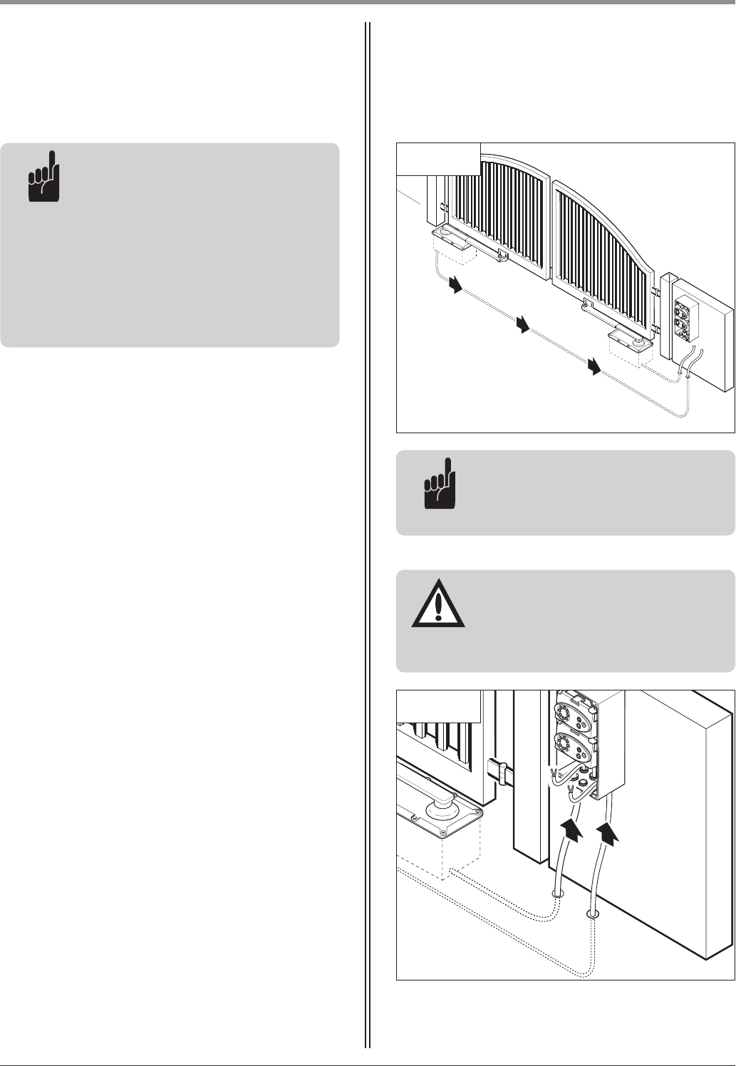
5.4 Cabling layout . . . . . . . . . . . . . . . . . . . . . . . . . . . . . . . . . . . . . . . . . . . . . . . . . . . . . . . . . . . . . . . . . . . .10
6. Installation . . . . . . . . . . . . . . . . . . . . . . . . . . . . . . . . . . . . . . . . . . . . . . . . . . . . . . . . . . . . . . . . . . . . . . . . . . .11
6.1 Mounting conditions . . . . . . . . . . . . . . . . . . . . . . . . . . . . . . . . . . . . . . . . . . . . . . . . . . . . . . . . . . . . . . .11
6.2 Installing the foundation box . . . . . . . . . . . . . . . . . . . . . . . . . . . . . . . . . . . . . . . . . . . . . . . . . . . . . . . . .11
6.3 Installing the motor unit . . . . . . . . . . . . . . . . . . . . . . . . . . . . . . . . . . . . . . . . . . . . . . . . . . . . . . . . . . . .13
6.4 Mounting the telescopic arm . . . . . . . . . . . . . . . . . . . . . . . . . . . . . . . . . . . . . . . . . . . . . . . . . . . . . . . . .14
6.5 Release . . . . . . . . . . . . . . . . . . . . . . . . . . . . . . . . . . . . . . . . . . . . . . . . . . . . . . . . . . . . . . . . . . . . . . . . .15
6.6 Fixing the control unit . . . . . . . . . . . . . . . . . . . . . . . . . . . . . . . . . . . . . . . . . . . . . . . . . . . . . . . . . . . . . .15
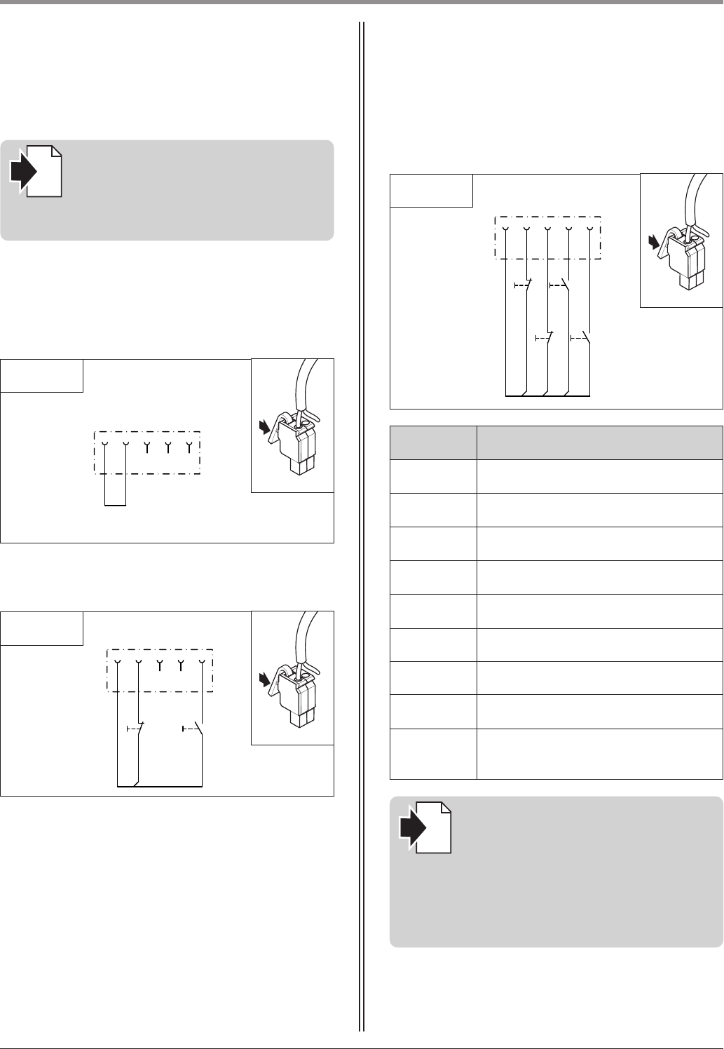
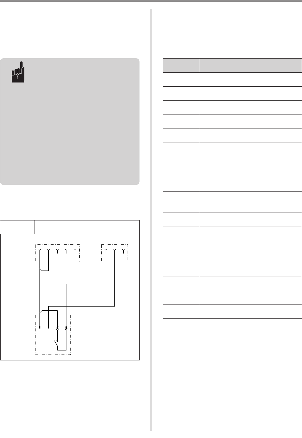
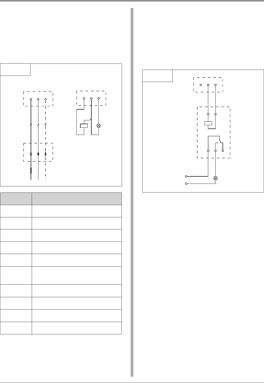
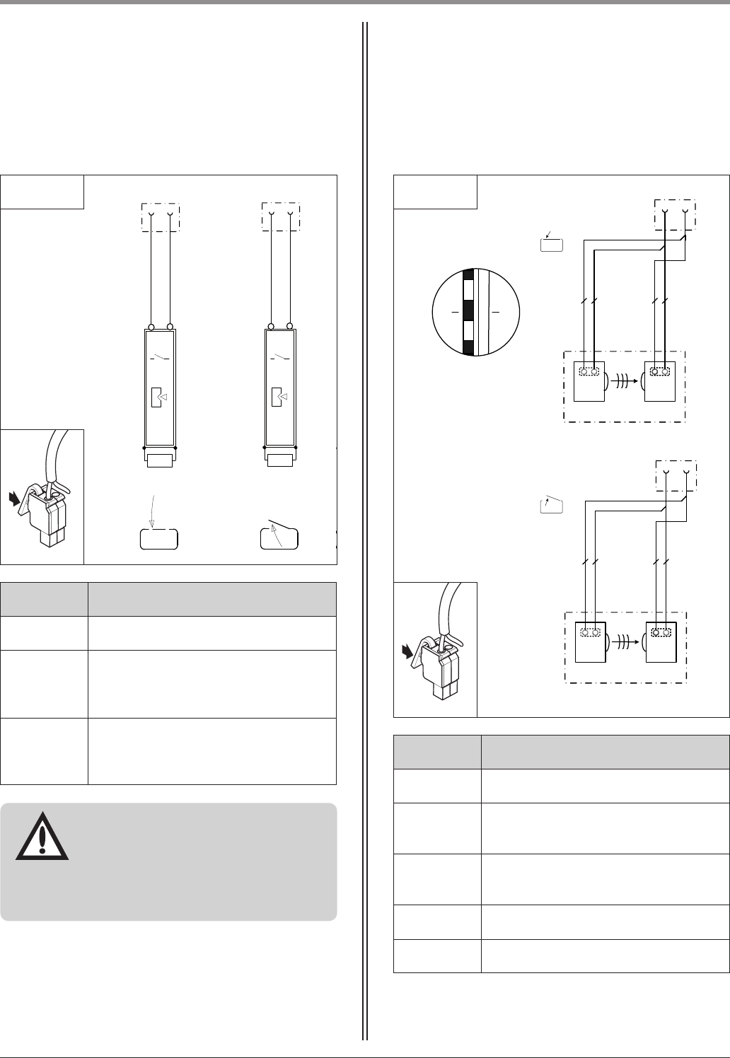
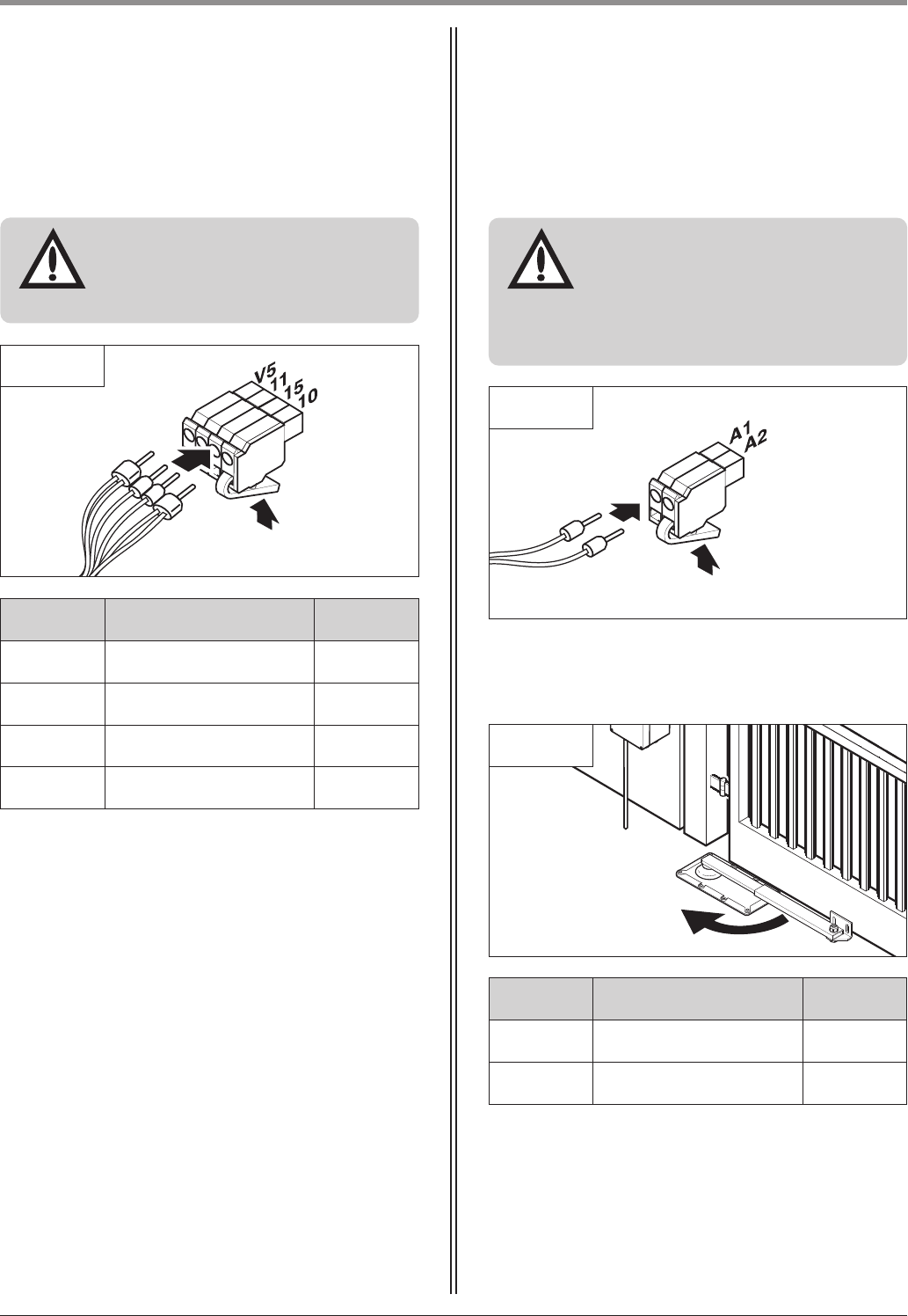
6.7 Connection of control elements . . . . . . . . . . . . . . . . . . . . . . . . . . . . . . . . . . . . . . . . . . . . . . . . . . . . . .16
6.8 Connecting the motor unit to the controls . . . . . . . . . . . . . . . . . . . . . . . . . . . . . . . . . . . . . . . . . . . . . . .21
6.9 Connection of the mains cable . . . . . . . . . . . . . . . . . . . . . . . . . . . . . . . . . . . . . . . . . . . . . . . . . . . . . . .24
7. Hand transmitter . . . . . . . . . . . . . . . . . . . . . . . . . . . . . . . . . . . . . . . . . . . . . . . . . . . . . . . . . . . . . . . . . . . . . .25
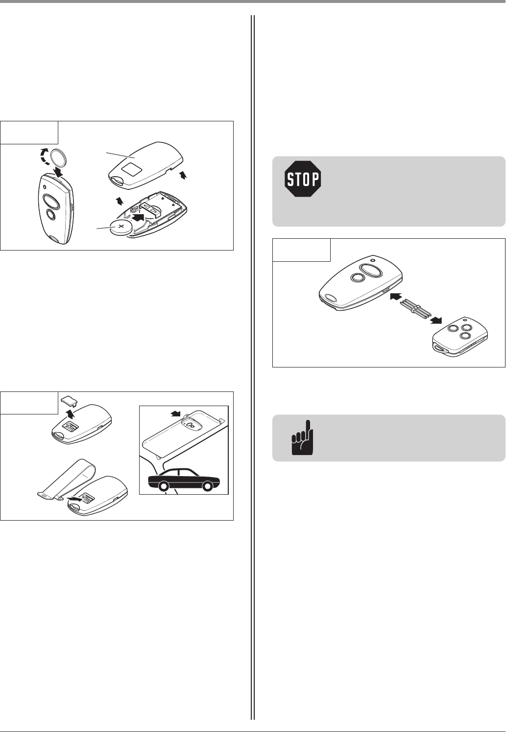
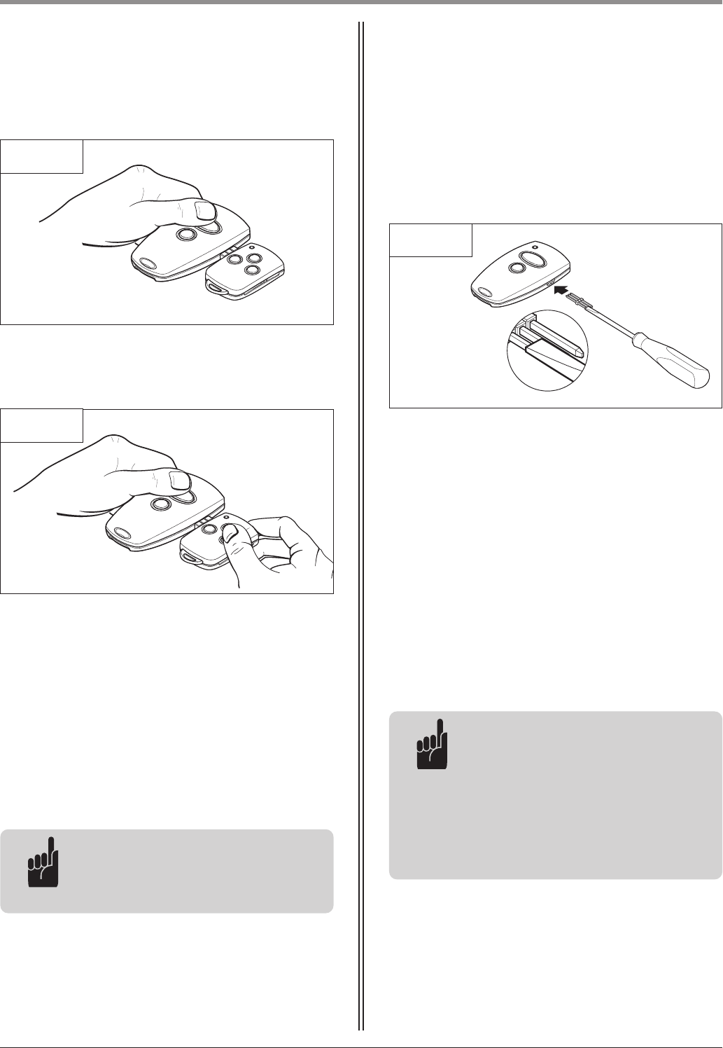
7.1 Operation and accessories . . . . . . . . . . . . . . . . . . . . . . . . . . . . . . . . . . . . . . . . . . . . . . . . . . . . . . . . . . .25
7.2 Hand transmitter coding . . . . . . . . . . . . . . . . . . . . . . . . . . . . . . . . . . . . . . . . . . . . . . . . . . . . . . . . . . . .26
8. Initial operation . . . . . . . . . . . . . . . . . . . . . . . . . . . . . . . . . . . . . . . . . . . . . . . . . . . . . . . . . . . . . . . . . . . . . . .28
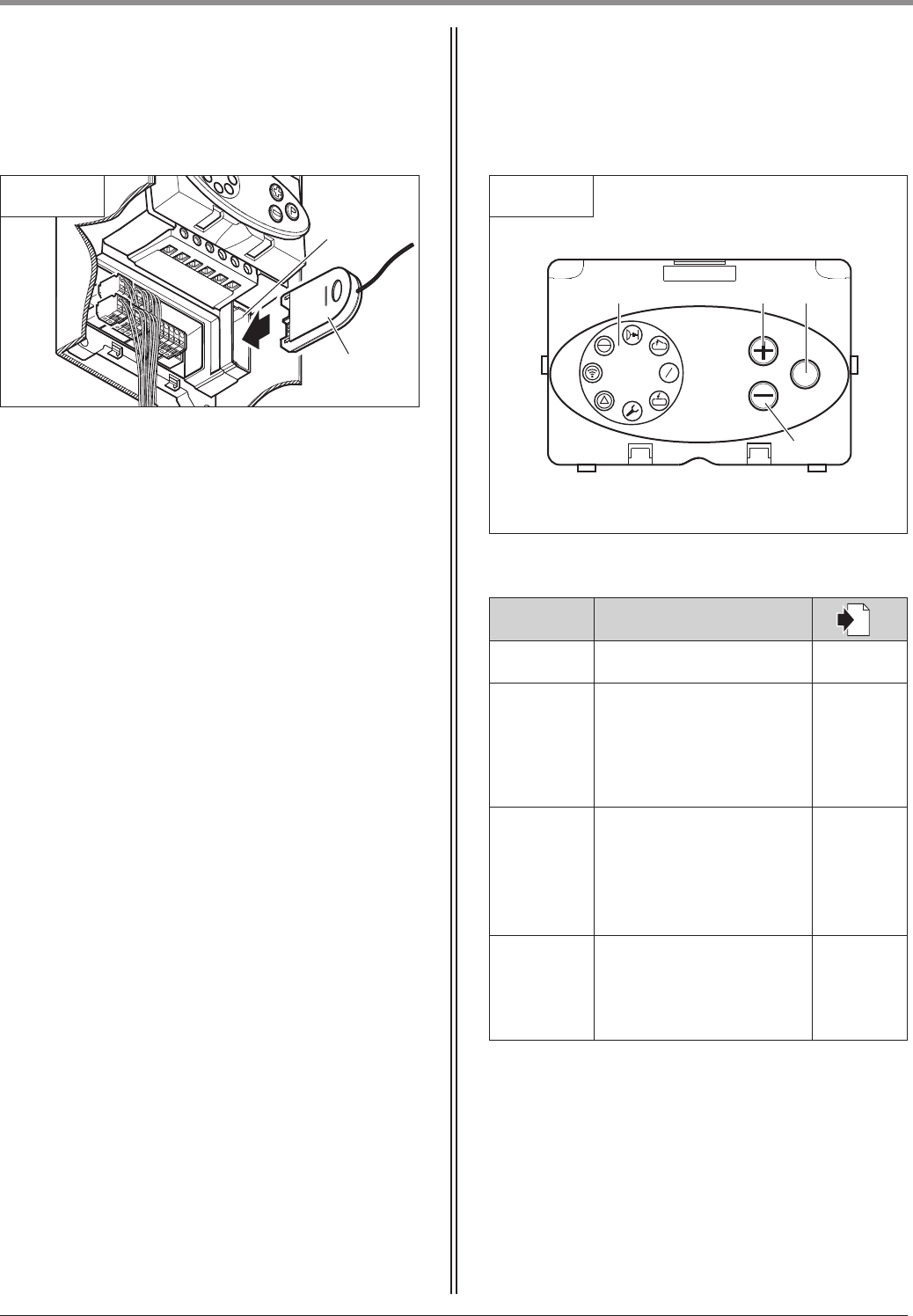
8.1 Connecting the modular antenna . . . . . . . . . . . . . . . . . . . . . . . . . . . . . . . . . . . . . . . . . . . . . . . . . . . . .28
8.2 Overview of the control unit . . . . . . . . . . . . . . . . . . . . . . . . . . . . . . . . . . . . . . . . . . . . . . . . . . . . . . . . .28
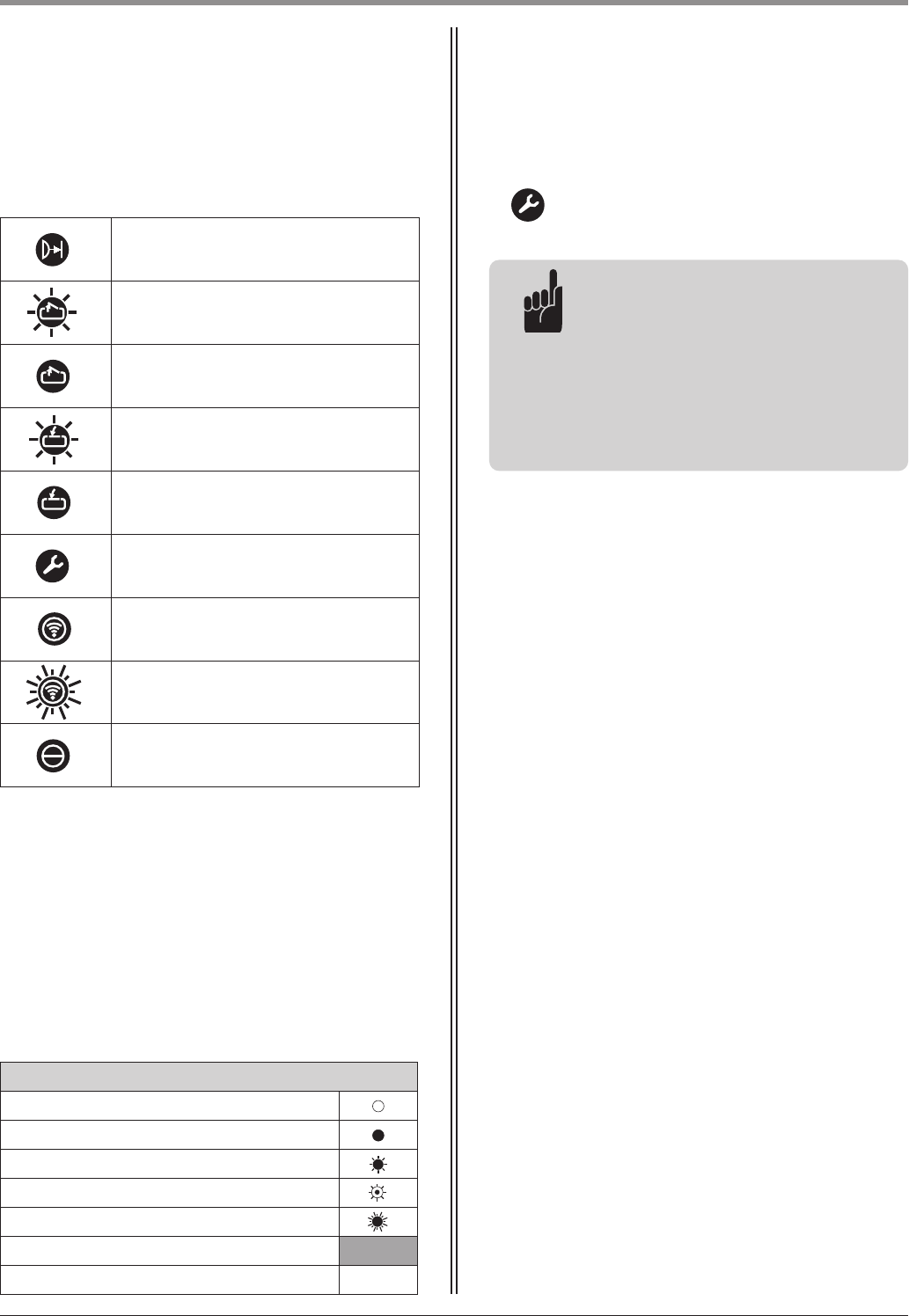
8.3 Overview of the display functions . . . . . . . . . . . . . . . . . . . . . . . . . . . . . . . . . . . . . . . . . . . . . . . . . . . . .29
8.4 Reference point . . . . . . . . . . . . . . . . . . . . . . . . . . . . . . . . . . . . . . . . . . . . . . . . . . . . . . . . . . . . . . . . . . .29
8.5 Express programming . . . . . . . . . . . . . . . . . . . . . . . . . . . . . . . . . . . . . . . . . . . . . . . . . . . . . . . . . . . . . .30
8.6 Function test . . . . . . . . . . . . . . . . . . . . . . . . . . . . . . . . . . . . . . . . . . . . . . . . . . . . . . . . . . . . . . . . . . . . .33
9. Extended operator functions . . . . . . . . . . . . . . . . . . . . . . . . . . . . . . . . . . . . . . . . . . . . . . . . . . . . . . . . . . . .34
9.1 General notes on extended operator functions . . . . . . . . . . . . . . . . . . . . . . . . . . . . . . . . . . . . . . . . . . .34
9.2 Programming structure for extended operator functions (Example for Level 2, Menu 2) . . . . . . . . . . . . .35
9.3 General overview of the programmable functions . . . . . . . . . . . . . . . . . . . . . . . . . . . . . . . . . . . . . . . . .36
9.4 Functions overview for the levels . . . . . . . . . . . . . . . . . . . . . . . . . . . . . . . . . . . . . . . . . . . . . . . . . . . . . .38
10. Messages . . . . . . . . . . . . . . . . . . . . . . . . . . . . . . . . . . . . . . . . . . . . . . . . . . . . . . . . . . . . . . . . . . . . . . . . . . . .48
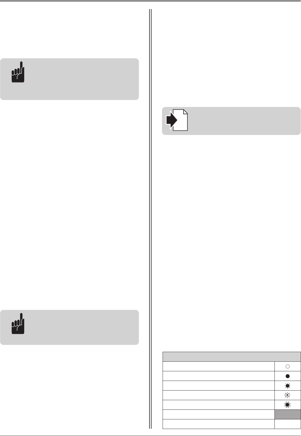
10.1 Status messages . . . . . . . . . . . . . . . . . . . . . . . . . . . . . . . . . . . . . . . . . . . . . . . . . . . . . . . . . . . . . . . . . .48
10.2 Fault messages . . . . . . . . . . . . . . . . . . . . . . . . . . . . . . . . . . . . . . . . . . . . . . . . . . . . . . . . . . . . . . . . . . . .48
10.3 Rectifying faults . . . . . . . . . . . . . . . . . . . . . . . . . . . . . . . . . . . . . . . . . . . . . . . . . . . . . . . . . . . . . . . . . . .50
11. Attachment . . . . . . . . . . . . . . . . . . . . . . . . . . . . . . . . . . . . . . . . . . . . . . . . . . . . . . . . . . . . . . . . . . . . . . . . . .53
11.1 Connection diagram Comfort 580 . . . . . . . . . . . . . . . . . . . . . . . . . . . . . . . . . . . . . . . . . . . . . . . . . . . . .53
11.2 Technical data for Comfort 580 . . . . . . . . . . . . . . . . . . . . . . . . . . . . . . . . . . . . . . . . . . . . . . . . . . . . . . .54
11.3 Declaration of Incorporation . . . . . . . . . . . . . . . . . . . . . . . . . . . . . . . . . . . . . . . . . . . . . . . . . . . . . . . . .55
11.4 EC Declaration of Conformity . . . . . . . . . . . . . . . . . . . . . . . . . . . . . . . . . . . . . . . . . . . . . . . . . . . . . . . .56
Operating Instructions, Comfort 580 GB (#91636) 5
4.1 Comfort 580 supply package
4. Product overview
4.1 / 1
1
2
Single wing gate system
1 Foundation box
2 Motor unit
3 Telescopic arm
4 Shims (4x)
5 Spacer cylinder
6 Cover plate
7 Protective rubber fitting
8 Set of screws for bracket
4.1 / 3
9 Control x.51
10 Handle
1 Foundation box (2x)
2 Motor unit (2x)
3 Telescopic arm (2x)
4 Shims (8x)
5 Spacer cylinder (2x)
6 Cover plate (2x)
7 Protective rubber fitting (2x)
8 Set of screws for bracket (2x)
Double wing gate system
Control unit
3
4
5
The Comfort 580 standard delivery package comprises:
- motor unit
- controls
- fixing materials for controls
and motor unit
- remote control
The Comfort 580 is available in the following versions,
as required:
9
6
7
8
1
2
3
4
5
6
7
8
4.1 / 2
6 Operating Instructions, Comfort 580 GB (#91636)
4. Product overview
!
5
!”
!#
4.1 / 4
11 Screws 3.5 x 32 (4x)
12 Wall plugs S6 (4x)
13 13 Spacer elements (2x)
14 Screw fixing insert with 2 flat cable openings
15 M20 screw fixing with flat cable insert
16 M20 screw fixing with round cable insert
17 M16 screw fixing with round cable insert
Mounting kit for control unit
!^
4.1 / 5
18 Hand transmitter
19 Sun visor clip
20 Module antenna
21 Transmission plug
Remote control
!\
„¯
4.2 / 1
Comfort 580
4.2 Dimensions
„∏
150
300
168
112
270
72
8
Operating Instructions, Comfort 580 GB (#91636) 7
4.3 / 1
The standard supply package is suitable for
the following types of gate.
Single wing gate system
4.3 / 2
Double wing gate system
5.1 General notes
The pictures in these instructions are not true-to-scale.
Dimensions are always given in millimetres (mm)!
The motor unit and the controls must be mounted on
the inside of the gate system.
For correct mounting you will need the following
tools:
5.1 / 1
13 / 17 / 22 / 24 13
2 2 / 5 ø 6 ø 6.5
M 8
5. Preparation for mounting
4.3 Gate variations
4. Product overview
8 Operating Instructions, Comfort 580 GB (#91636)
5.2 Checks
Attention!
In order to guarantee correct
mounting, carry out the following
checks before installing.
5. Preparation for mounting
Advice:
The use of an electric lock is
recommended.
Foundations
• Check the proposed position of the foundation.
Supply package
• Check the package to ensure that all the parts are
included.
• Check that you have all the additional components
that are necessary for your particular installation
requirements.
Gate system
• Ensure that your gate system has an appropriate
electricity supply connection and a facility for
disconnecting the mains. The minimum cross-
sectional area of the earth cable is 3 x 1.5 mm
2
.
• Ensure that all cables are suitable for outdoor use
(UV resistant and cold resistant).
• Ensure that your gate system has a gate stop in the
CLOSE and OPEN directions.
• Disassemble the door latches or render them inop-
erable.
• Ensure that the gate can be easily moved by hand.
• Observe the following gate requirements.
Gate wing width: min. 1 m - max. 2.5 m
Gate height: max. 2.5 m
Gate wing weight: max. 250 kg
Open space: min. 50%
Gate incline: The gate must be horizontal.
Operating Instructions, Comfort 580 GB (#91636) 9
5. Preparation for mounting
A Conduit for control cable
B Drainage pipe for foundation box
q Gate length (max. 2.50 m)
r Below the depth of frost penetration
5.3 Gate and foundation layout
r
A
B
5.3 / 1
Attention!
In order to avoid damage to the foundation,
- the specified size of the foundation must be adhered to,
- the foundation box must be positioned at the centre of the foundation.
Motor unit parallel to the gate
r
q
A
B
5.3 / 2
Motor unit at right angles to the gate
q
>250
> 400
>250
>400
10 Operating Instructions, Comfort 580 GB (#91636)
5. Preparation for mounting
5.4 Cabling layout
5.4 / 1
2 x 0.75 mm
2
8 x 0.75 mm
2
8 x 0.75 mm
2
2 x 0.4 mm
2
2 x 0.4 mm
2
2 x 0.4 mm
2
2 x 0.4 mm
2
3 x 1.5 mm
2
230 V / AC
3 x 1.5 mm
2
Advice:
This is just an example of a cabling layout; the layout can vary according to the type of gate and the
associated equipment.
Reference:
The relevant instructions are to be followed for the installation and cabling of the gate sensors and
the operating and safety elements.
i
1 Photocell
2 Photocell
3 Signal light
4 Code button, transponder, ...
5 Key switch
6 Mains isolator switch (mains disconnection facility)
7 Electric lock
8 Stop plate
9 Mains supply cable
10 Closing edge safety device (CESD)
2
23
4
6
9
7
1
1
8
5
Operating Instructions, Comfort 580 GB (#91636) 11
6.1 Mounting conditions
6.1 / 1
Mounting position of motor unit
Attention!
To ensure proper operation,
- the foundation box must be concreted
in place in a foundation block,
- all the specified conditions must be
met,
- all the specified dimensions must be
complied with.
6.1 / 2
The distance between the upper edge of the foundation
box and the lower edge of the gate wing must be at
least 55 mm.
6.2 Installing the foundation box
• Place the foundation box (A) in the prepared opening.
• Position the foundation box (A) in the middle of the
opening. Observe the specified installation conditions.
• Connect the conduit (B) for the control cable to the
foundation box (A).
• Connect the drainage pipe (C) to the foundation
box.
• Seal the joints where the conduit (B) and the drainage
pipe (C) connect to the foundation box (A).
6.2 / 1
• Place the spacer cylinder (D) in the foundation box (A).
6.2 / 2
Clearance between gate wing and ground
Advice:
For greater clearance values, a suitable
fitting must be fixed to the gate.
≤ 100430 - 470
0 - 40
> 55
A
B
C
A
D
6. Installation
12 Operating Instructions, Comfort 580 GB (#91636)
6. Installation
• Close the foundation box (A) with the cover plate (E).
• Seal the cover plate (E) using self-adhesive tape.
6.2 / 3
A
E
• Infill the space surrounding the foundation box with
concrete.
6.2 / 4
Advice:
To ensure that the motor unit functions
properly, the foundation box must not
be allowed to change position during
concreting.
• Check that the foundation box is horizontal.
• Allow the foundation concrete to set.
• Remove the self-adhesive tape and the cover plate (E).
• Remove the spacer cylinder (D).
6.2 / 5
Attention!
To prevent damage to the foundations
occurring and the drive position from
slipping, the foundation block must
have set completely before the next
step is carried out.
D
E
Operating Instructions, Comfort 580 GB (#91636) 13
6. Installation
6.3 / 1
Attention!
To allow the motor unit to be taken
out at a later date, at least 35 cm of
control cable must be left loose in the
foundation box.
6.3 Installing the motor unit
• Place the four galvanised shims (A) in the corners of
the foundation box (B).
6.3 / 2
• Feed the control cable through the conduit.
• Pull the cable through to its connection position at
the control unit.
• Lower the motor unit (C) into the foundation box (B).
A
B
B
C
Tip:
If the motor unit has to be taken out of
the foundation box at a later date, two
of the screws can be replaced with the
longer screws (supplied) to make this
process easier. Before lowering the
motor unit back into the foundation
box, the short screws must be put back
into place.
6.3 / 3
14 Operating Instructions, Comfort 580 GB (#91636)
6. Installation
6.4 / 1
6.4 Mounting the telescopic arm
• Place the protective rubber fitting (B) on the telescopic
arm (C).
• Push the protective rubber fitting (B) tightly onto the
motor unit.
• Push the telescopic arm (C) on to the motor unit (A).
Advice:
The telescopic arm must be mounted
between the OPEN and CLOSED
positions. The mounting position
ensures that the reference point is
switched with every gate movement.
B
A
C
6.4 / 2
• Drive the gate to the gate OPEN position.
• Drive the gate to the gate CLOSED position
If the telescopic arm has an overlap of at least
90 mm whatever the gate position, the bracket can
be screwed to the gate.
• Screw the bracket to the gate.
C
> 90
Before the telescopic arm can be permanently fixed to
the gate, the correct position for the bracket screws
must be determined. In order to adjust the bracket
position, the motor unit must first be connected to the
control unit.
• Clamp the bracket of the telescopic arm (C) securely
to the gate using a screw clamp.
• Connect the motor unit to the control unit.
• Put the control unit into operation.
Reference:
Connecting the motor unit to the
control unit is described in Section 6.8.
Putting the control unit into operation
is described in Sections 8.1 to 8.6.
i
Operating Instructions, Comfort 580 GB (#91636) 17
6. Installation
Connection option 2:
Reference:
The connection configuration depends
on the programming of the special
functions. Depending on the program-
ming, impulse or direction buttons can
be connected.
Programming the special functions is
described in Section 9.4 (Level 5).
i
-SB5
12 11
-SB3
14 13
-SB3 4
12 11
-SB8
14 13
-XB99
B9 5 34 3 8
6.7 / 4
Label Type / function
3 Connection for intermediate position
5 Stop connection
8 Impulse connection
34 Connection for closing prevention device
B9 +24 V DC connection
SB3 Button for intermediate position
SB5 STOP button
SB8 Impulse button
SB34
Button for closing prevention device /
Drive system stops and reverses
M06E039
-XB99
B9 5 34 3 8
M06E039
Terminal XB99
Factory settings:
B9 and 5 bridged
Connection option 1:
-SB5
12 11
-SB8
14 13
-XB99
B9 5 34 3 8
6.7 / 2
6.7 / 3
M06E039
Reference:
When installing external control
elements, or safety and signal
equipment, the relevant instructions
must be observed.
i
18 Operating Instructions, Comfort 580 GB (#91636)
- XB99
B9 5
34
3 8
- XH01
15 16 17
- X1
+
-
- S1
14 13
1 2
M07E027
6. Installation
Advice:
If a closing prevention device
(photocell, timer, …) is connected to
XB99, the controls will recognise it
automatically after “Mains On”
(contact SB34 must be closed).
The photocell can be deactivated later
(Level 8 / Menu 1).
When the contacts of a closing
prevention device are open, the gate
can no longer be closed.
Additional external control elements,
and safety and signal devices with 24 V
connections must be connected to
XB99 and XH01.
Connection option 3:
- External radio receiver
6.7 / 5
Label Type / function
XB99 Connection of external control elements
3 Connection for intermediate position
5 Stop connection
8 Impulse connection
34 Connection for closing prevention device
B9 24 V DC connection
X1 Connection for external receiver
1
Connection of potential-free normally open
contact
2
Connection of potential-free normally open
contact
+ 24 V DC connection
- GND connection
S1
Normally open contact, receiver,
potential-free
XH01 Connection of control unit output
15 Connection for electric lock, 24 V DC
16 GND connection
17 Connection for programmable output
Operating Instructions, Comfort 580 GB (#91636) 19
Terminals XN81/XH01 Connection option:
- Connection for signal light with external relay
6. Installation
- XN81
- X0
L
PE
N
N
L
PE
- F0
L
N
PE
6.7 / 6
16
15
17
- YH15
- HH17
- XH01
- XH01
16
15
17
1411
12
A2 A1
- KH17
- HH14
L
N
M07E039
M07E038
6.7 / 7
M07E038
Label Type / function
L Connection for phase
N Connection for neutral wire
PE Earth wire connection
15 / 16 Connection for electric lock, 24 V DC
16 GND connection
16 / 17
Connection of programmable output
(24 V DC / 0.5 A)
HH14 Signal light
HH17 Signal light 24 V
KH17 User’s relay 24 V
YH15 Electric lock (provided by the customer)
20 Operating Instructions, Comfort 580 GB (#91636)
Terminals XP54A / XP54B
Label Type / function
P5 GND connection
46
Connection for signal of closing edge safety
device
Gate travelling direction OPEN (XP54B)
47
Connection for signal of closing edge safety
device
Gate travelling direction CLOSE (XP 54A)
Attention!
If an 8.2 kΩ contact strip closing edge
safety device is connected, the 8.2 kΩ
resistors installed at terminals XP54B
closing edge OPEN and XP54A closing
edge CLOSE must be removed.
Label Type / function
P6 GND connection
26
Connection for photocell signal
gate travelling direction OPEN (XP62B)
27
Connection for signal of photocell, gate
travelling direction CLOSE (XP62A)
RX Receiver for the two-wire photocell
TX Transmitter for the two-wire photocell
Terminals XP62A / XP62B
- XP54B
P5
46
- XP54A
P5 47
8K2
8K2
- XP54B
P5
46
8K2
M07E037
6.7 / 8
- XP62A
P6 27
TX
RX
- W1
2
1
- W2
2
1
1
2
- W1
- W2
- AP27
-
- XP62B
P6 26
TX
RX
- W1
2
1
- W2
2
1
- AP26
M07E036
6.7 / 9
6. Installation
Operating Instructions, Comfort 580 GB (#91636) 21
6. Installation
Advice:
A two-wire photocell connected to
terminals XP62B / XP62A will be
recognised automatically by the
controls after “Mains On”.
The photocell can be deactivated later
(Level 8 / Menu 1).
If the contacts of a closing prevention
device are open, the gate can no longer
be closed.
6.8 Connecting the motor unit to the
controls
6.8 / 1
Advice:
For double wing gate systems, both
motor supply cables must be laid to the
control unit.
6.8 / 2
• Feed the cables from the motor units into the control
unit through the screw fixings.
Attention!
In order to guarantee the protection
grade of the controls, the cable must
be passed through the correct screw
fixing.
22 Operating Instructions, Comfort 580 GB (#91636)
6.8 / 4
Attention!
To ensure that the operator system
functions properly, the rotational
direction of the motor unit must be
taken into consideration when
connecting the motor leads.
6.8 / 5
Terminal Colour system
Number
system
A1 White lead 1
A2 Brown lead 2
The operator system turns the gate clockwise to
OPEN it
Terminal XM70A/XM70B
• Fix the leads in the rpm detector plug.
6.8 / 3
Attention!
To ensure that the operator system
functions properly, the polarity of the
plugs must be correct.
Terminal Colour system
Number
system
V5 Red lead / Grey lead 3 / 6
11 Black lead 4
15 Blue lead 7
10 Pink lead / Lilac lead
5 / 8
6. Installation
Terminal XV51A/XV51B
7. Hand transmitter
26 Operating Instructions, Comfort 580 GB (#91636)
7.2 Hand transmitter coding
7.2.1 Transfer the coding
Advice:
The plug connections on both sides of
the hand transmitter are identical.
Using this function it is possible to transfer the coding
of a hand transmitter that has already been
programmed for operating the operator system
(master transmitter) to another hand transmitter.
• Connect both transmitters with the enclosed
transmission plug.
Caution!
Before operating the hand transmitter,
ensure that there are neither persons
nor objects in the operating range of
the gate.
7.2.1 / 1
E Back of hand transmitter
F Battery 3V CR 2032
• Open the back of the hand transmitter (E),
e.g. with a coin.
• Change the battery (F) and observe correct poling.
F
E
Visor clip, for attaching the hand transmitter to a visor
in a car.
7.1 / 2
7.1 / 3
Accessory
Change batteries
Operating Instructions, Comfort 580 GB (#91636) 27
7. Hand transmitter
Advice:
For multi-channel hand transmitters,
the coding procedure has to be carried
out for each button separately.
• Actuate the master transmitter and hold the button.
The transmitter LED lights up.
• Whilst keeping the button on the master transmitter
depressed, press the desired button on the other
hand transmitter.
The LED flashes.
After 1 -2 seconds, the LED on the newly programmed
transmitter lights up permanently.
The programming procedure is complete.
The coding of the master transmitter has now been
transferred to the other hand transmitter.
• Remove the transmission plug.
7.2.1 / 2
7.2.1 / 3
7.2.2 Change coding
If a hand transmitter has been lost, this function can
be used to change the coding of the remaining remote
control transmitters.
• Connect one end of the transmission plug to the
hand transmitter.
• At the free end of the transmission plug, short-circuit
one of the outer pins with the centre pin adjacent to
it (e.g. using a screw driver).
• Press the desired button on the hand transmitter.
A new code is then generated by the integrated
random coding facility.
The LED flashes quickly.
As soon as the LED lights up permanently, the hand
transmitter has been programmed with a new code.
The button can then be released and the transmission
plug removed.
Advice:
After the hand transmitter has been
re-programmed, the operator system
must also be re-programmed to
respond to the new code.
For multi-channel transmitters, the
programming process must be carried
out for each button separately.
7.2.2 / 1
P
1
2
3
4
5
6
7
8
1
2
BAD
C
8.2 / 1
8.2 Overview of the control unit
8.1 / 1
A
B
• Insert the modular antenna (A) into the antenna
socket (B) in the controls.
8.1 Connecting the modular antenna
8. Initial operation
Operating elements
Label Type / function
i
A Carousel display 8.3
B
OPEN button (+)
(e.g. to drive the gate to
the OPEN position or to
increase parameters when
programming)
-
C
CLOSE button (-)
(e.g. to drive the gate to
the CLOSED position or to
decrease parameters when
programming)
-
D
STOP button (p)
(e.g. to switch to
programming mode or
to save parameters)
-
28 Operating Instructions, Comfort 580 GB (#91636)
8. Initial operation
8.4 Reference point
In operating mode, LED 5 lights up briefly
when an object/person passes the reference
point.
Advice:
In the factory default setting and after
a reset, the controls are set to start in
the CLOSED gate position.
To ensure trouble-free programming,
therefore, the gate and the operator
system must be in the CLOSED end
position before resetting or carrying out
the express programming procedure.
Photocell or the CESD has been interrupted
(display: master only)
Gate moving towards OPEN position
(display: master and slave)
Gate in OPEN position
(display: master and slave)
Gate moving towards CLOSED position
(display: master and slave)
Gate in CLOSED position
(display: master and slave)
Reference point is switched
(display: master and slave)
Permanent actuation of an external control
element (display: master only)
Remote control is actuated
(display: master only)
Operating voltage
(display: master and slave)
LED displays in operating mode
Legend:
LED off
LED on
LED flashes slowly
LED pulses
LED flashes quickly
Factory default setting
Not possible
8.3 Overview of the display functions
Operating Instructions, Comfort 580 GB (#91636) 29
8. Initial operation
8.5 Express programming
Test run (only necessary after resetting)
Before carrying out the express programming procedure,
the drive system (with the gate coupled up) must be
driven to the factory default OPEN and CLOSED gate
positions using the (+) and (-) buttons.
• Carry out a test run (MASTER and SLAVE).
Express programming
The basic functions of the operator system are set
during the express programming procedure.
MASTER:
- Gate position GATE OPEN
- Gate position GATE CLOSED
- Remote controls
SLAVE (only for double wing gates):
- Gate position GATE OPEN
- Gate position GATE CLOSED
The programming procedure is a consecutive process.
It is essential that this procedure be carried out.
After express programming has been completed and a
learning run has been carried out to set the automatic
cut-out at the OPEN and CLOSED gate positions, the
operator system is ready for operation.
8.5.1 General notes on express programming
Advice:
When programming the OPEN and
CLOSED gate positions, the reference
point must be passed.
8.5.2 Programming buttons
The controls are programmed using the plus (+),
minus (-) and (P) buttons.
If no buttons are pressed within 120 seconds while in
programming mode, the controls revert to operating
mode.
A corresponding message is displayed.
Reference:
The messages are explained in
Section 10.
i
Advice:
For proper initial operation of the
operator system, the express
programming procedure must be
carried out.
• Carry out the express programming according to the
following procedure.
Legend:
LED off
LED on
LED flashes slowly
LED pulses
LED flashes quickly
Factory default setting
Not possible
30 Operating Instructions, Comfort 580 GB (#91636)
18

Hulp nodig? Stel uw vraag in het forum

Spelregels
1

Forum

Marantec-Control-x.51
  • Ik wil een extra drukknop "Schneider Electric Harmony XALD102" aansluiten op mijn Marantec Control x.51.
    Op welke ingangen moet deze aangesloten worden? Gesteld op 24-7-2024 om 12:03

    Reageer op deze vraag Misbruik melden

Misbruik melden

Gebruikershandleiding.com neemt misbruik van zijn services uitermate serieus. U kunt hieronder aangeven waarom deze vraag ongepast is. Wij controleren de vraag en zonodig wordt deze verwijderd.

Product:

Bijvoorbeeld antisemitische inhoud, racistische inhoud, of materiaal dat gewelddadige fysieke handelingen tot gevolg kan hebben.

Bijvoorbeeld een creditcardnummer, een persoonlijk identificatienummer, of een geheim adres. E-mailadressen en volledige namen worden niet als privégegevens beschouwd.

Spelregels forum

Om tot zinvolle vragen te komen hanteren wij de volgende spelregels:

Belangrijk! Als er een antwoord wordt gegeven op uw vraag, dan is het voor de gever van het antwoord nuttig om te weten als u er wel (of niet) mee geholpen bent! Wij vragen u dus ook te reageren op een antwoord.

Belangrijk! Antwoorden worden ook per e-mail naar abonnees gestuurd. Laat uw emailadres achter op deze site, zodat u op de hoogte blijft. U krijgt dan ook andere vragen en antwoorden te zien.

Abonneren

Abonneer u voor het ontvangen van emails voor uw Marantec Control x.51 bij:


U ontvangt een email met instructies om u voor één of beide opties in te schrijven.


Ontvang uw handleiding per email

Vul uw emailadres in en ontvang de handleiding van Marantec Control x.51 in de taal/talen: Engels als bijlage per email.

De handleiding is 3,38 mb groot.


U ontvangt de handleiding per email binnen enkele minuten. Als u geen email heeft ontvangen, dan heeft u waarschijnlijk een verkeerd emailadres ingevuld of is uw mailbox te vol. Daarnaast kan het zijn dat uw internetprovider een maximum heeft aan de grootte per email. Omdat hier een handleiding wordt meegestuurd, kan het voorkomen dat de email groter is dan toegestaan bij uw provider.

Stel vragen via chat aan uw handleiding

Stel uw vraag over deze PDF

Andere handleiding(en) van Marantec Control x.51

Marantec Control x.51 Gebruiksaanwijzing - Deutsch - 58 pagina's

Marantec Control x.51 Gebruiksaanwijzing - Deutsch - 58 pagina's

Marantec Control x.51 Gebruiksaanwijzing - Français - 58 pagina's


Uw handleiding is per email verstuurd. Controleer uw email

Als u niet binnen een kwartier uw email met handleiding ontvangen heeft, kan het zijn dat u een verkeerd emailadres heeft ingevuld of dat uw emailprovider een maximum grootte per email heeft ingesteld die kleiner is dan de grootte van de handleiding.

Er is een email naar u verstuurd om uw inschrijving definitief te maken.

Controleer uw email en volg de aanwijzingen op om uw inschrijving definitief te maken

U heeft geen emailadres opgegeven

Als u de handleiding per email wilt ontvangen, vul dan een geldig emailadres in.

Uw vraag is op deze pagina toegevoegd

Wilt u een email ontvangen bij een antwoord en/of nieuwe vragen? Vul dan hier uw emailadres in.


Info