743689
1
Verklein
Vergroot
Pagina terug
1/46
Pagina verder
M1 - D/GB/I 360314 - M - 0.5 - 1109
English Copyright.
No part of this manual may be reproduced without our prior
consent.
Subject to changes which are in the interest of technical
improvements.
Stand: 05.2010
#90461
Deutsch Urheberrechtlich geschützt.
Nachdruck, auch auszugsweise, nur mit unserer Genehmigung.
Änderungen, die dem technischen Fortschritt dienen,
vorbehalten.
Italiano Tutti i diritti riservati.
Riproduzione, anche parziale, solo previa nostra autorizzazione.
La ditta si riserva la facoltà di apportare modifiche in base al
progresso tecnologico.
Betriebsanleitung
Operating instructions
Istruzioni d’uso
Control 410
Rolltorsteuerung
Roller shutter controls
Centralina per motori tubolari
7 Dati tecnici
91
Istruzioni d’uso Control 410
Dati tecnici
Tensione di funzionamento 230 V~ / 50 Hz
Assorbimento 3W
Potenza max motore 600VA
Sicurezza interna
(motore e centralina)
2,5 A
Carico max sul contatto per
lampeggiante
6 A, 250V~, 2000VA
Alimentazione per fotocellula 12 V DC / max. 70 mA
Dispositivi di sicurezza collegabili
Stop d’emergenza, fungo, costa
sensibile (8,2 kOhm, Fraba OSE)
Temperature ammesse -20 °C fino a 60 °C
Dimensioni quadro (l x b x h) 180mm x 95mm x 57mm
Grado di protezione IP 64
Collegamenti dei cavi M16 x 1,5 morsettiera: 5 ... 10mm
Solo con accessori radio opzionali:
Frequenza radio 868,3 MHz
Codifica radio Multibit
Numero max radiocomandi
28 (attenzione: se si programmano
più di 28 radiocomandi, viene
sovrascritto sempre il più vecchio
90
Istruzioni d’uso Control 410
Normativa vigente
6 Normativa vigente
La centralina per motori tubolari Control 410 rispetta le seguenti norme:
EN 60335-1:2007 Sicurezza per i dispositivi elettrici per uso domestico
e similare
EN 61000-6-3:2001 Immunità
EN 61000-6-2:2005 Compatibilità elettromagnetica
Inoltre, durante l’installazione e la messa in funzione occorre rispettare anche
le seguenti norme:
EN 12453:2000 Sicurezza nelle porte motorizzate Requisiti
EN 60204-1:2005 Sicurezza del macchinario
Equipaggiamento elettrico delle macchine
Regole generali
EN ISO 13849-1:2006 Sicurezza del macchinario Parti dei sistemi di
comando legate alla sicurezza
Parte 1: Regole generali
VDE 0100:1973 Requisiti per l’installazione di impianti con voltaggio
fino a 1000 V
BGR232:2003 Direttiva per finestre, porte e portoni motorizzati
3
Inhalt
Betriebsanleitung Control 410
Inhalt
1 Allgemeines . . . . . . . . . . . . . . . . . . . . . . . . . . . . . . . . . . . . . . . . . .4
2 Produktbeschreibung . . . . . . . . . . . . . . . . . . . . . . . . . . . . . . . . . .5
2.1 Lieferumfang . . . . . . . . . . . . . . . . . . . . . . . . . . . . . . . . . . . . . . . .5
2.2 Bedien- und Anzeigeelemente . . . . . . . . . . . . . . . . . . . . . . . . . .6
2.3 Merkmale . . . . . . . . . . . . . . . . . . . . . . . . . . . . . . . . . . . . . . . . . . .7
3 Sicherheitshinweise . . . . . . . . . . . . . . . . . . . . . . . . . . . . . . . . . . . .8
4 Installation und Inbetriebnahme . . . . . . . . . . . . . . . . . . . . . . . . . .9
4.1 Installationsschritte . . . . . . . . . . . . . . . . . . . . . . . . . . . . . . . . . . .9
4.2 Installationshinweise . . . . . . . . . . . . . . . . . . . . . . . . . . . . . . . . .10
4.3 Funktionseinheiten . . . . . . . . . . . . . . . . . . . . . . . . . . . . . . . . . . .11
4.4 Befehlsgeber . . . . . . . . . . . . . . . . . . . . . . . . . . . . . . . . . . . . . . .12
4.4.1 Befehlstasten am Steuergehäuse . . . . . . . . . . . . . . . . . . . .12
4.4.2 Externer Schlüsselschalter . . . . . . . . . . . . . . . . . . . . . . . . . .12
4.4.3 Funkbedienung . . . . . . . . . . . . . . . . . . . . . . . . . . . . . . . . . . .12
4.5 Sicherheitseinrichtungen . . . . . . . . . . . . . . . . . . . . . . . . . . . . . .13
4.5.1 Allgemeines . . . . . . . . . . . . . . . . . . . . . . . . . . . . . . . . . . . . .13
4.5.2 Nothalt (Schlagtaster), Abrollsicherung . . . . . . . . . . . . . . . .13
4.5.3 Interner Schlüsselschalter . . . . . . . . . . . . . . . . . . . . . . . . . .13
4.5.4 Schließkantensicherung . . . . . . . . . . . . . . . . . . . . . . . . . . . .14
4.6 Anschlusspläne . . . . . . . . . . . . . . . . . . . . . . . . . . . . . . . . . . . . .20
4.6.1 Anschlussplan allgemein . . . . . . . . . . . . . . . . . . . . . . . . . . .20
4.6.2 Anschlussplan Beleuchtung . . . . . . . . . . . . . . . . . . . . . . . . .21
4.7 Voreinstellungen . . . . . . . . . . . . . . . . . . . . . . . . . . . . . . . . . . . .21
4.7.1 Allgemeines . . . . . . . . . . . . . . . . . . . . . . . . . . . . . . . . . . . . .21
4.7.2 Totmannbetrieb aktivieren/deaktivieren . . . . . . . . . . . . . . . .22
4.7.3 Sicherheitseinrichtungen . . . . . . . . . . . . . . . . . . . . . . . . . . .23
4.7.4 Motorlaufzeit und Laufzeittoleranz . . . . . . . . . . . . . . . . . . . .24
4.7.5 Funksteuerung . . . . . . . . . . . . . . . . . . . . . . . . . . . . . . . . . . .26
5 Fehlerzustand . . . . . . . . . . . . . . . . . . . . . . . . . . . . . . . . . . . . . . . .28
5.1 Allgemeines . . . . . . . . . . . . . . . . . . . . . . . . . . . . . . . . . . . . . . . .28
5.2 Rücksetzen der Steuerung (RESET) . . . . . . . . . . . . . . . . . . . .28
5.3 Fehlerzustände . . . . . . . . . . . . . . . . . . . . . . . . . . . . . . . . . . . . .29
5.3.1 Sicherheits-LED blinkt und andere LED(s) leuchten . . . . . .29
5.3.2 Betriebs-LED und andere LEDs blinken . . . . . . . . . . . . . . .29
6 Normen und Vorschriften . . . . . . . . . . . . . . . . . . . . . . . . . . . . . .30
7 Technische Daten . . . . . . . . . . . . . . . . . . . . . . . . . . . . . . . . . . . . .31
4
Betriebsanleitung Control 410
Allgemeines
1 Allgemeines
Die vorliegende Bedienungsanleitung ist darauf ausgerichtet, den
fachkundigen Installateur bei der Montage, Einstellung und Inbetriebnahme
der Roll torsteuerung zu unterstützen. Natürlich kann auch der Benutzer z.B.
bei Unklarheiten der Bedienung in den entsprechenden Kapiteln nachlesen.
Änderungen an den Einstellungen oder an der Verdrahtung dürfen jedoch nur
durch eine Fachkraft ausgeführt werden.
Die Anleitung ist so aufzubewahren, dass diese im Fall eines Eingriffs durch
die Fachkraft jederzeit verfügbar ist.
Ergänzend zu dieser Anleitung sind unbedingt die einschlägigen Normen und
Vorschriften zu beachten, auf welche in Kapitel 6 (S. 30) verwiesen wird.
Im Text finden verschiedene Symbole Anwendung. Die Bedeutung dieser
Symbole stellt sich wie folgt dar:
Hinweis, allgemeine Information
Gefahr durch elektrischen Strom
Allgemeine Warnung
Für technische Änderungen wird keine Haftung übernommen.
89
Istruzioni d’uso Control 410
Errori
5.3 Segnalazioni di errore
5.3.1 Il LED di sicurezza lampeggia e altri LED sono
accesi
Motore difettoso, oppure il motore ha bisogno di troppa
corrente
Die È possibile comandare la serranda solo a uomo presente, tramite la
pulsantiera del quadro della centralina, posto che i pulsanti siano stati
precedentemente abilitati tramite il selettore a chiave. Il funzionamento
dell’impianto non è più corretto. Contattare l’installatore responsabile
dell’impianto
Viene superata la limitazione del ciclo operativo, la
serranda non si muove agevolmente, fine corsa difettoso
È possibile comandare la serranda solo a uomo presente, tramite la
pulsantiera del quadro della centralina oppure il selettore a chiave esterno,
posto che i pulsanti siano stati precedentemente abilitati tramite il selettore a
chiave integrato. Il funzionamento dell’impianto non è più corretto. È
eventualmente possibile resettare l’errore interrompendo l’alimentazione
elettrica. Contattare l’installatore responsabile dell’impianto!
Dispositivo di sicurezza difettoso
Se l’errore è stato eliminato e l’ostacolo rimosso, questa
segnalazione di errore scompare automaticamente, perché i dispositivi di
sicurezza vengono testati dalla centralina ogni 2 minuti. Mentre l’errore è
attivato è possibile aprire automaticamente la serranda utilizzando tutti i
dispositivi di comando programmati, mentre è possibile chiudere la serranda
solo a uomo presente.
5.3.2 Il LED di funzionamento e altri LED lampeggiano:
Nel caso di questa segnalazione di errore esiste un problema di natura
tecnica nella programmazione. Eseguire un reset come descritto al capitolo
5.2.1. Se anche in questo caso il problema non si risolve, rivolgersi
all’installatore responsabile dell’impianto.
Una volta effettuato un reset completo, occorre naturalmente
riprogrammare tutte le impostazioni (dispositivi di sicurezza,
limitazione del ciclo operativo, radiocomando etc.).
88
Istruzioni d’uso Control 410
Errori
5 Errori
5.1 Informazioni generali
La centralina Control 410 possiede diverse caratteristiche di sicurezza per prevenire danni ed
incidenti durante il normale funzionamento. Ad esempio realizza un auto-test permanente dei
dispositivi di sicurezza collegati, una limitazione del ciclo operativo del motore e diversi auto-test
interni.
Se viene riconosciuto un errore la centralina entra nella modalità di errore. Questo è riconoscibile
immediatamente perché i LED di segnalazione sull’esterno al quadro cominciano a lampeggiare.
Per specificare meglio il tipo di errore occorre poi verificare la segnalazione realizzata dai LED
all’interno della centralina. La panoramica al capitolo 5.3 descrive i possibili errori che possono
verificarsi.
A seconda del tipo di errore, è possibile che temporaneamente non sia più possibile muovere la
serranda in modo automatico e che la centralina permetta solo il funzionamento a uomo presente
nella direzione compromessa dall’errore. È possibile comandare la serranda solo a uomo
presente, tramite la pulsantiera del quadro della centralina oppure il selettore a chiave esterno,
posto che i pulsanti siano stati precedentemente abilitati tramite il selettore a chiave integrato.
Non appena si rilascia il pulsante, la serranda si arresta. Questo tipo di funzionamento ha la
priorità rispetto a tutti i dispositivi di sicurezza eventualmente collegati.
Poiché nel funzionamento a uomo presente i dispositivi di sicurezza sono
disattivati, è possibile comandare la serranda solo mantenendola in vista.
5.2 Reset della centralina
5.2.1 Reset parziale
Con il reset parziale la centralina viene semplicemente riportata alla normale modalità di
funzionamento, pertanto tutte le impostazioni e i codici dei radiocomandi restano nella
memoria della centralina. Per effettuare un reset parziale, occorre interrompere
l’alimentazione di rete per almeno 3secondi (togliendo la spina dalla presa di rete, oppure
rimuovendo il fusibile).
5.2.2 Reset completo
Effettuando un reset completo, tutti i valori memorizzati nella centralina
vengono riportati a quelli di fabbrica, pertanto tutte le impostazioni effettuate
(dispositivi di sicurezza, limitazione del ciclo operativo, radiocomandi) vanno
perdute.
1. Interrompere l’alimentazione di rete.
2. Tenendo premuto il tasto “Funzione”, ripristinare l’alimentazione
3. Continuare a tenere premuto il tasto “Funzione” per circa 10 secondi, fino a che non si
accendo il LED di funzionamento.
5
Produktbeschreibung
Betriebsanleitung Control 410
2 Produktbeschreibung
2.1 Lieferumfang
Gemeinsam mit der Rolltorsteuerung und der vorliegenden Anleitung befinden
sich bei der Auslieferung folgende Teile im Paket:
- Netzanschlussleitung 3 x 0,75 mm², Außendurchmesser ca. 6,5 mm, mit
Schutzkontaktstecker
- 5 Kabelverschraubungen M16 x 1,5
- 5 Verschlussschrauben M16 x 1,5
- 4 Schraubenabdeckungen für Steuerungsgehäuse
- 4 Schrauben 4 x 35 mm zur Wandbefestigung
- 4 Spreizdübel S6
- Ersatzsicherung 2,5 A träge, 5 x 20
- 2 Schlüssel
Vor Beginn der Installation ist zu prüfen, ob alle Teile vorhanden sind.
6
Betriebsanleitung Control 410
Produktbeschreibung
2.2 Bedien- und Anzeigeelemente
Betriebsanzeige: - leuchtet grün, wenn die Steuerung eingeschaltet ist.
- blinkt bei interner Störung.
Sicherheitsanzeige: - verlischt wenn alle angeschlossenen
Sicher heits einrichtungen betriebsbereit und nicht
ausgelöst sind.
- leuchtet rot bei ausgelöster Sicherheitseinrichtung.
- blinkt bei Fehler.
Abb. 2-1: Bedien- und Anzeigeelemente
87
Istruzioni d’uso Control 410
Tutti i 28 radiocomando vengono completamente cancellati secondo il
seguente schema:
Installazione e messa in funzione
86
Istruzioni d’uso Control 410
Installazione e messa in funzione
4.7.5 Radiocomando
Non è possibile impostare un radiocomando se si è attivato il funzionamento
a uomo presente. La centralina supporta max 28 codici radio di diversi
radiocomandi. Ognuno di questi radiocomandi deve essere memorizzato nella
centralina nel seguente modo.
Se si è attivato il funzionamento a uomo presente non è possibile
memorizzare nuovi radiocomandi e vengono cancellati tutti quelli
precedentemente già memorizzati.
Memorizzazione del radiocomando (passo 5)
La procedura di memorizzazione deve essere effettuata a serranda ferma
secondo il seguente schema:
7
Produktbeschreibung
Betriebsanleitung Control 410
2.3 Merkmale
Die Rolltorsteuerung Control 410 bietet die Möglichkeit, Rohrmotoren mit
integrierter Endabschaltung bis zu einer Leistungsaufnahme von 600 VA zu
betreiben. Das Anwendungsgebiet liegt bei privat und gewerblich genutzten
Garagen to ren und Toreinfahrten. Ein Einsatz der Steuerung mit Rollgitter to ren
oder sonstigen Toren mit Öffnungen und Durchbrüchen ist nur im
Totmannbetrieb (Kap. 4.7.2) zulässig!
Fahrbefehle an das Tor können über die integrierten Richtungstasten, einen
extern anschließbaren Schlüsselschalter oder mittels Funk Handsender erteilt
werden.
Die Einstellung von Betriebsparametern geschieht menügeführt über 6 LED
Anzeigen im Inneren des Gehäuses. Zwei Leuchtdioden machen die
wichtigsten Betriebszustände der Steuerung nach außen sichtbar.
8
Betriebsanleitung Control 410
Sicherheitshinweise
3 Sicherheitshinweise
Die Rolltorsteurung Control 410 wird nach dem aktuellen Stand
der Technik gefertigt und entspricht den anerkannten
sicherheitstechnischen Regeln. Trotzdem sind
Gefahrensituationen nicht ausgeschlossen. Um dieses Risiko zu
minimieren, müssen einige Hinweise befolgt werden:
- Lesen Sie die Betriebsanleitung vor der Installation und Inbetriebnahme
aufmerksam.
- Der Einsatz der Steuerung mit Rollgitter to ren oder sonstigen Toren mit
Öffnungen und Durchbrüchen ist nur im Totmannbetrieb zulässig!
- Die Benutzung der Steue rung von Kindern oder nicht autorisierten
Personen ist durch geeignete Maßnahmen auszuschließen.
- Die Rolltorsteuerung darf nur in einwandfreiem Zustand in Betrieb
genommen werden.
- Die Installation der Steuerung sowie die Einstellung der Betriebsparameter
darf nur durch fachkundige, entsprechend geschulte Personen
durchgeführt werden.
- Bei der Installation sind die einschlägigen Normen und Richtlinien
unbedingt zu beachten.
- Bei Verdrahtungsarbeiten ist die Steuerung stets vom Netz zu trennen.
- Angeschlossene Sicherheitseinrichtungen dürfen nicht überbrückt oder
durch anderweitige Maßnahmen außer Kraft gesetzt werden.
- Die Funktion der Sicherheitseinrichtungen ist in einem Rhythmus von ca.
6 Monaten oder mindestens 1x jährlich zu überprüfen.
- Eigenmächtige Umbauten, z.B. das Anbringen von zusätzlichen
Bohrun gen im Gehäuse, der Einsatz anderer Sicherungstypen usw., sind
nicht zulässig.
- Bei Störungen oder Schäden ist der zuständige Installateur zu
verständigen.
- Kinder nicht mit der Torsteuerung spielen lassen.
- Funk Handsender von Kindern fernhalten.
- Die Reinigung des Gehäuses ist mit einem feuchten Lappen
durchzuführen. Lösungsmittel, welche das Gehäuse angreifen, dürfen nicht
verwendet werden.
85
Istruzioni d’uso Control 410
Attenzione! Durante la procedura di misurazione del ciclo
operativo (da 2 a 3 aperture o chiusure automatiche della
serranda) non si devono inviare altri comandi (ad esempio da
pulsante o radiocomando). Inoltre occorre assicurarsi che i
dispositivi di sicurezza non rilevino ostacoli durante la procedura
di misurazione. Se queste regole non vengono rispettate, la
procedura di misurazione viene interrotta.
Tolleranza della limitazione del ciclo operativo (passo 4)
La durata del ciclo operativo in determinati casi ha delle variazioni dipendenti
ad esempio dalle stagioni dell’anno, dalla temperatura o da altri eventi esterni.
Perciò è necessario che la limitazione del ciclo operativo sia gestita con una
determinata tolleranza, in modo da venire incontro alle variazioni descritte e
da evitare che la centralina vada in errore (vedere capitolo 5).
La tolleranza da impostare deve essere valutata dall’installatore a seconda
delle caratteristiche della specifica serranda automatica. È possibile impostare
i valori 4s, 5s, 6s, 7s (in secondi).
Per impostare la tolleranza occorre richiamare il menu 4 premendo 4 volte il
tasto “Menu”e scegliere il valore desiderato premendo poi il tasto “Funzione”
(tenendo premuto il tasto più di 1,6 secondi):
Una volta effettuata l’impostazione, uscire dal menu premendo il tasto “Menu”.
Installazione e messa in funzione
84
Istruzioni d’uso Control 410
Installazione e messa in funzione
4.7.4 Limitazione del ciclo operativo e relativa tolleranza
Procedura di apprendimento della limitazione del ciclo operativo (passo 3)
Dopo l’installazione di una serranda occorre impostare nella centralina la
limitazione del ciclo operativo del motore nelle direzioni di apertura e
chiusura. Questa operazione è necessaria per motivi di sicurezza: se ad
esempio dovessero essere difettosi i fine corsa interni del motore, il motore
non si fermerebbe mai e la serranda verrebbe danneggiata meccanicamente.
Se la centralina viene utilizzata a uomo presente, la limitazione del ciclo
operativo deve essere memorizzata con aperture a uomo presente, altrimenti
la centralina non lo apprenderebbe correttamente. Non è importante da quale
posizione della serranda si inizia la procedura di memorizzazione del ciclo
operativo. Una volta terminata la procedura (da 2 a 3 aperture o chiusure
della serranda), la serranda rimane nella posizione di fine corsa di Apertura.
A serranda ferma occorre attenersi al seguente schema:
9
Installation und Inbetriebnahme
Betriebsanleitung Control 410
4 Installation und Inbetriebnahme
4.1 Installationsschritte
Um die Steuerung in Betrieb zu nehmen, sind mindestens die nachfolgend
auf geführten Schritte in der angegebenen Reihenfolge abzuarbeiten. Danach
ist eine Torbedienung am Steuerungsgehäuse oder über einen
Funk hand sen der möglich. Ergänzende Installationen können bei Bedarf im
Nachhinein durch geführt werden. Für die grundlegenden Funktionen hat dies
jedoch keine Auswirkungen.
Sollte die Steuerung während der Installation und
Inbetrieb nah me in den Fehlermodus wechseln (Sicherheits LED
oder Betriebs LED blinkt), da z.B. die Einstellungen noch nicht
korrekt vorgenommen wurden, kann das Rücksetzen (Reset, s.
Kap. 5.2, S. 28) in den normalen Be triebs mo dus durch Trennen
der Steuerung vom Netz für mindestens 3 Sekunden geschehen
(Stecker ziehen, Entfernen der Siche rung, o.ä.).
Schritt Beschreibung Verweis
1 Steuerung installieren Kap. 4.2
2 Endlagen des Motors einstellen Beschreibung Motorhersteller
3
Motor an Steuerung anschließen
Steuerung an Netz anschließen
Kap. 4.2
Kap. 4.6
4
Betriebsart auswählen (Totmannbetrieb
aktivieren/deaktivieren)
Kap. 4.7.2
5
Sicherheitseinrichtungen anschließen
(Abrollsicherung, OSE, Kontaktleiste 8,2 kOhm,
Lichtschranke...)
Beschreibung der
Sicherheitseinrichtung Kap. 4.5
6
Schließkantensicherung und evtl. Lichtschranke
im Menü aktivieren
Kap. 4.7.3
7 Funktion der Sicherheitseinrichtung testen Kap. 4.7.3
8
Torlaufzeit in Steuerung einlernen
Laufzeittoleranz einstellen
Kap. 4.7 .4
9 Handsender einlernen Kap. 4.7.5
10
Betriebsanleitung Control 410
Installation und Inbetriebnahme
4.2 Installationshinweise
Die Rolltorsteuerung wird mit 4 Schrauben (Lieferumfang) an der Wand
befestigt.
Achtung! Der Montageort der Steuerung muss so gewählt sein,
dass bei der Bedienung der integrierten Befehls tas ten immer ein
freier Blick auf das Tor vorhanden ist. Die Benutzung der Steue rung
von Kindern oder nicht autorisierten Personen ist durch geeignete
Maßnahmen auszuschließen.
Als Höhe für die Wandmontage gilt minimal 1,50 m und maximal 1,90 m. Ein
sicherer Abstand zu bewegten Teilen ist unbedingt einzuhalten.
Die Kabel ver schraubungen müssen stets nach unten gerichtet sein!
Alle Anschlüsse im Inneren des Steuerungsgehäuses sind mit abnehmbaren
Schraubklemmen für starre und flexible Leitungen bis 2,5 mm² oder für
feindrähtige Leiter mit Aderendhülse bis 1,5 mm² ausgeführt.
Die Stromversorgung erfolgt einphasig aus dem 230V Netz (L, N, PE).
Achtung! Eine allpolige Trennung vom Netz muss jederzeit möglich
sein. Hierfür kommt ein Hauptschalter, eine Steck ver bin dung o.ä. in
Frage. Fest angeklemmte Netzanschlüsse, z.B. Un terputzdosen,
sind nicht zulässig. Im gewerblichen Bereich ist die Trennein richtung
gegen unbeabsichtigtes oder unbefugtes Wieder ein schalten zu si chern. Wird
eine Anschluss leitung mit Steckvorrichtung verwendet, so muss die Steckvor -
richtung nach Montage des Gerätes zugänglich sein. Die Steck dose selbst ist
stets geerdet nach VDE0100 auszuführen.
Der zu steuernde 230V Antriebsmotor muss Anschlüsse für die Richtungen
“Auf” und “Zu”, Nullleiter und Schutzleiter besitzen. Die Klemmenbelegung
entnehmen Sie bitte dem Anschlussplan (Ab bildung 4.8, Seite 20 ).
Die Motor an schlüs se AUF, ZU und Nullleiter müssen stets direkt an die
Steuerung angeklemmt werden.
Das Hoflicht oder die Beleuchtung der Garage wird mit einer Ausschalt ver -
zögerung von 3 Minuten geschaltet (siehe Seite 21, Anschluss Beleuchtung).
Achtung! Ein Absicherung des Stromkreises für die Beleuchtung ist
in der Steuerung nicht vorhanden und muss deshalb extern realisiert
werden.
4.7.3 Dispositivi di sicurezza (passo 2)
I dispositivi di sicurezza collegati, come una fotocosta ottica OSE, una costa
sensibile elettrica e una fotocellula devono essere abilitate nella centralina.
Per fare questo occorre richiamare il Menu 3 premendo 3 volte il tasto
“Menu” e poi scegliere con il tasto “Funzione” la variante da applicare:
Per il collegamento elettrico dei dispositivi di sicurezza, vedere
il capitolo. 4.5.
Una volta impostata la variante corrispondente all’effettiva installazione, uscire
dal menu premendo 2 volte il tasto “Menu”.
Se è stato impostato il funzionamento a uomo presente, la
centralina non effettua l’autotest dei dispositivi di sicurezza.
La verifica dei dispositivi di sicurezza può essere facilmente
realizzata tramite il LED nel quadro della centralina, che si
spegne se un dispositivo di sicurezza rileva un ostacolo.
Installazione e messa in funzione
83
Istruzioni d’uso Control 410
4.7.2 Attivare/disattivare il funzionamento a uomo
presente (passo 1)
La centralina in combinazione ad esempio con una saracinesca con funzionamento a
uomo presente può essere comandata solo tramite i pulsanti di direzione “Apertura” e
“Chiusura”oppure tramite l’uscita “Pulsante”. Il selettore a chiave interno deve essere
nella posizione contrassegnata dal puntino nero. Durante il funzionamento a uomo
presente non viene effettuato l’autotest dei dispositivi di sicurezza eventualmente
collegati.
Non è possibile il funzionamento con radiocomando. Per motivi di sicurezza, attivando
il funzionamento a uomo presente vengono cancellati tutti gli eventuali codici radio già
memorizzati nella centralina e non è possibile memorizzarne nuovi.Premendo due
volte il tasto “Menu” e successivamente il tasto “Funzione” viene attivato (il LED di
sicurezza lampeggia lentamente) oppure disattivato il funzionamento a uomo presente.
82
Istruzioni d’uso Control 410
Installazione e messa in funzione
Con il tasto “Menu” si sceglie il menu (1 ... 4) da modificare. Con il tasto
“Funzione” all’interno di un singolo menu vengono scelti il valore o
l’impostazione da memorizzare (A, B).
Per richiamare un determinato menu occorre premere il tasto “Menu” varie
volte, fino a che non si illumina il relativo LED. All’interno del menu, in
maniera analoga viene scelto il valore da memorizzare. Dopo l’impostazione
dell’ultimo menu la centralina torna al normale stato di funzionamento.
Si consiglia di seguire l’ordine delle operazioni indicato al capitolo 4.1, cioè di
collegare e configurare per primi i dispositivi di sicurezza, a meno che la
centralina non debba funzionare solo a uomo presente. Successivamente si
consiglia di impostare la limitazione del ciclo operativo del motore e la sua
tolleranza. In conclusione si dovrà memorizzare il codice del radiocomando.
Totmannbetrieb aktiviert
A
B
Totmannbetrieb deaktiviert
11
Installation und Inbetriebnahme
Betriebsanleitung Control 410
4.3 Funktionseinheiten
Die folgende Abbildung zeigt die Steuerungsplatine im Innern des Gehäuses.
Der Zugriff darauf ist bei der Installation und der Konfiguration vor der ersten
Inbetriebnahme notwendig.
Abb. 4-1: Funktionselemente
12
Betriebsanleitung Control 410
Installation und Inbetriebnahme
4.4 Befehlsgeber
4.4.1 Befehlstasten am Steuerungsgehäuse
Die Betätigung einer der beiden Richtungstasten am Steuerungsgehäuse im
normalen Betriebszustand bewirkt die automatische Fahrt des Tores in die
jeweilige Richtung. Um eine Torbewegung zu stoppen, ist die andere Taste zu
drücken.
In bestimmten Fehlerfällen, z.B. wenn eine Sicherheitseinrichtung ausgelöst
oder defekt ist, ist die Auf- und Abbewegung des Tores nur noch im s.g.
Tot mann-Betrieb möglich. Das Tor kann dann nur bewegt werden sola nge
die Richtungstaste am Steuerungsgehäuse gedrückt wird oder der externe
Schlüsselschalter geschaltet wird. Nach Los lassen der Taste stoppt das Tor
sofort. Die Benutzung der Richtungstasten ist in diesem Fall nur möglich,
wenn die Tasten zuvor mit dem Schlüsselschalter an der Steuerung
freigeschaltet wurden. Alle anderen Befehlsgeber sind in diesem Be triebs fall
deaktiviert.
Bei Auslösen der Abrollsicherung ist keine Torbewegung möglich. Auch nicht
im Totmann-Betrieb.
4.4.2 Externer Schlüsselschalter
Über den Eingang externer Schlüsselschalter, Klemmen 8 und 9, welcher als
Schließerkontakt auszuführen ist, geschieht die Befehlsgabe AUF > STOPP >
ZU > STOPP > ...
Achtung! Da über diesen Eingang Totmann-Betrieb möglich ist,
dürfen keine anderen Befehlsgeber angeschlossen werden.
4.4.3 Funkbedienung
Eine optimale Möglichkeit das Tor zu steuern, liegt in der Verwendung eines
Funk Handsenders in Verbindung mit dem in der Steuerung bereits
eingebauten Funk Empfangs modul.
Die Steuerung ist für die 1Tast-Bedienung ausgelegt. Drücken Sie die
Sen der taste das erste Mal bewegt sich das Tor in eine Richtung. Beim
zweiten Mal stoppt die Torbewegung, beim dritten Mal fährt das Tor in die
Gegen rich tung (AUF > STOPP > ZU > STOPP > AUF > STOPP > ...). Der
Tastencode des Handsenders muss vorab in die Steuerung eingelernt
werden. Lesen Sie hierzu bitte Kapitel 4.7.5, Seite 26.
81
Installazione e messa in funzione
Istruzioni d’uso Control 410
4.6.2 Schema di collegamento illuminazione
Il collegamento dell’illuminazione esterna avviene internamente alla centralina
come contatto pulito normalmente aperto e deve essere realizzato come
descritto nella figura seguente:
4.7 Predisposizioni
4.7.1 Informazioni generali
Prima della messa in funzione occorre impostare correttamente i
parametri di funzionamento della Control 410 (passi 1-4, vedere pag. 22).
Senza queste impostazioni non è possibile garantire un corretto
funzionamento della centralina.
La configurazione avviene utilizzando i tasti ed il display a 6 LED all’interno
della centralina. Tutte le impostazioni restano memorizzate anche in caso di
assenza di corrente elettrica.
Figura 4-9: Collegamento dell’illuminazione
Figura 4-10: Pannello per le predisposizioni
80
Istruzioni d’uso Control 410
Installazione e messa in funzione
4.6 Schemi di collegamento
4.6.1 Schema di collegamento generale
La figura 4-8 mostra il collegamento ai singoli morsetti. Ai morsetti di sinistra
vengono collegati tutti i dispositivi di sicurezza e di comando. Ai morsetti di
destra vengono collegati i dispositivi con alimentazione di rete a 230 V.
Attenzione! I collegamenti al motore di Apertura, Chiusura e
Neutro devono sempre essere collegati direttamente alla
centralina. Il collegamento del Neutro direttamente dalla rete
al motore comporta la distruzione della centralina
elettronica!
Figura 4-8: Schema di collegamento
13
Betriebsanleitung Control 410
Installation und Inbetriebnahme
4.5 Sicherheitseinrichtungen
4.5.1 Allgemeines
Je nach Art des Tores, nach Verwendungszweck und nach der
Benutzer grup pe ist ein notwendiger Ausstattungsgrad mit
Sicherheitseinrichtungen vorgeschrieben. Um die richtige Kombination für den
jeweiligen Anwendungsfall zu finden müssen ggf. die unter Kap. 6 genannten
Vorschriften konsultiert werden. Diese sind unbedingt einzuhalten. Es liegt in
der Verantwortung des Instal lateurs, die Sicherheitseinrichtungen
vorschriftsmäßig anzubringen, die Steue rung entsprechend zu konfigurieren
und die Wartungsintervalle der Si cherheitseinrichtungen abzusichern. Üblich
ist ein Wartungsintervall von 6 Monaten. Sicherheitseinrichtungen dürfen
keinesfalls außer Kraft gesetzt oder in sonstiger Art und Weise unwirksam
gemacht werden.
Generell ist der Status der Sicherheitseinrichtungen durch die rote
Sicher heits anzeige (s. Abb. 2-1) am Steuerungsgehäuse ablesbar:
“Sicherheit” aus: Alle Sicherheitseinrichtungen o.k. und nicht ausgelöst.
“Sicherheit” ein: mind. eine Sicherheitseinrichtung ausgelöst.
“Sicherheit” blinkt: Fehler liegt vor (siehe Kap. 5).
Vorraussetzung für die korrekte Anzeige des Zustands der
Sicherheitsein rich tungen ist natürlich, dass die Konfiguration der Steuerung
entsprechend durch geführt1wurde (Kap. 4.7).
4.5.2 Nothalt (Schlagtaster), Abrollsicherung
Im normalen Betriebszustand muss eine Verbindung zwischen den Klemmen
1 und 2 vorhanden sein. Wird die Verbindung aufgehoben, ist keine Torbewe -
gung mehr möglich, auch nicht im Totmann-Betrieb. Eine laufende Bewegung
bricht sofort ab. Dieser Eingang dient unter anderem zum Anschluss einer
Abrollsicherung und möglicherweise weiterer Öffnerkontakte (z.B. Schlag -
taster). Bei Nichtverwendung des Nothalts muss eine Brücke eingefügt sein.
4.5.3 Interner Schlüsselschalter
Im Störfall kann das Tor in Richtung ZU nur noch im Totmannbetrieb
(Steuerung ohne Selbst haltung) mit den Richtungstasten oder dem externen
Schlüsselschalter gefahren werden. Der Gesetz geber fordert für den Einsatz
in öffentlichen Be rei chen (auch private Garagentore) für den Totmannbetrieb,
die zusätzliche Sicherung der Steuerung ge gen Fremd betä tigung.
Der eingebaute Schlüsselschalter dient der Freischaltung der
Richtungstasten und des externen Schlüsselschalters für den
Totmannbetrieb und muss hierzu auf Position schwarz stehen
und darf nur von unterwiesenen Personen geschaltet werden.
14
Betriebsanleitung Control 410
Installation und Inbetriebnahme
4.5.4 Schließkantensicherung
Zur Sicherung der Schließkante eines Tores sind verschiedene
Schaltleisten typen einsetzbar:
- elektromechanische Kontaktleiste mit Anschlusswiderstand 8,2 kOhm
- optische Schaltleiste (Marantec / Fraba “OSE”)
Elektromechanische Kontaktleiste 8,2 kOhm
Der Anschluss einer Schaltleiste mit Abschlusswiderstand 8,2 kOhm erfolgt
entsprechend Abbildung 4-2 (Erfüllt die Anforderungen der EN ISO 13849-1,
Kategorie 2/Performance Level “c”.).
Achtung! Durch konstruktive Maßnahmen am Tor ist ein
Aus lösen der Schaltleiste in der unteren Endlage zu unterbinden.
Abb. 4-2: Anschluss elektrische Kontaktleiste 8,2 kOhm
79
Installazione e messa in funzione
Istruzioni d’uso Control 410
Fotocellula Marantec a cavi tradizionali
Attenzione! Rispettare le polarità.
Informazione: il collegamento di una costa sensibile è
assolutamente necessario!
Figura 4-7: Collegamento di una fotocellula Marantec a cavi tradizionali
78
Istruzioni d’uso Control 410
Installazione e messa in funzione
Fotocellula (230 V ~) e fotocosta (Fraba OSE)
(in conformità alla norma EN ISO 13849-1, categoria 2/livello di performance
“c”)
Figura 4-6: Collegamento di una fotocellula (230 V ~) e di una fotocosta OSE
15
Betriebsanleitung Control 410
Installation und Inbetriebnahme
Optische Schaltleiste (Marantec / Fraba OSE)
Die OSE ist eine aktive Schaltleiste, welche eine Versorgungsspannung von
12 V DC zum Betrieb benötigt. Klemme 5 stellt eine entsprechende Spannung
zur Verfügung (Erfüllt die Anforderungen der EN ISO 13849-1, Kategorie 2/
Performance Level “c”.).
Achtung! Durch konstruktive Maßnahmen am Tor ist ein
Auslösen der Schaltleiste in der unteren Endlage zu unterbinden.
Abb. 4-3: Anschluss Schaltleiste
16
Betriebsanleitung Control 410
Installation und Inbetriebnahme
Visolux-Lichtschranke (12 V) und elektrische Kontaktleiste (8,2 kOhm)
(Erfüllt die Anforderungen der EN ISO 13849-1, Kategorie 2/ Performance
Level “c”.)
Achtung! Im Lichtschrankenempfänger LK 25 ist eine Brücke
von Klemme 1 auf Klemme 6 zu legen! Der Hell-Dunkel-Um -
schal ter ist nach unten zu schieben!
Abb. 4-4: Anschluss Visolux-Lichtschranke (12 V) und elektrische Kontaktleiste 8,2 kOhm
77
Istruzioni d’uso Control 410
Installazione e messa in funzione
Fotocellula Visolux (12 V) e costa sensibile elettrica (8,2 kOhm)
(in conformità alla norma EN ISO 13849-1, categoria 2/livello di performance
“c”)
Attenzione! Il selettore luce/buio deve essere abbassato!
Figura 4-5: Collegamento di una fotocellula Visolux (12V) e di una costa a induzione 8,2 kOhm
76
Istruzioni d’uso Control 410
Installazione e messa in funzione
Fotocellula Visolux (12 V) e costa sensibile elettrica (8,2 kOhm)
(in conformità alla norma EN ISO 13849-1, categoria 2/livello di performance
“c”)
Attenzione! Nella ricevente della fotocellula LK 25 occorre colle-
gare un ponte tra i morsetti 1 e 6! Il selettore luce/buio deve
essere abbassato!
Figura 4-4: Collegamento di una fotocellula Visolux (12V) e di una costa a induzione 8,2 kOhm
17
Betriebsanleitung Control 410
Installation und Inbetriebnahme
Visolux-Lichtschranke (12 V) und elektrische Kontaktleiste (8,2 kOhm)
(Erfüllt die Anforderungen der EN ISO 13849-1, Kategorie 2/ Performance
Level “c”.)
Achtung! Der Hell-Dunkel-Umschalter ist nach unten zu
schieben!
Abb. 4-5: Anschluss Visolux-Lichtschranke (12 V) und elektrische Kontaktleiste 8,2 kOhm
18
Betriebsanleitung Control 410
Installation und Inbetriebnahme
Lichtschranke (230 V ~) und optische Schaltleiste (Fraba OSE)
(Erfüllt die Anforderungen der EN ISO 13849-1, Kategorie 2/ Performance
Level “c”.)
Abb. 4-6: Anschluss Lichtschranke (230 V ~) und OSE
75
Istruzioni d’uso Control 410
Installazione e messa in funzione
Fotocosta ottica (Marantec /Fraba OSE)
La fotocosta OSE è una costa attiva che necessita un’alimentazione a 12 V
DC. Questo tipo di alimentazione viene fornito dal morsetto 5 (in conformità
alla norma EN ISO 13849-1, categoria 2/livello di performance “c”).
Attenzione! Occorre prevedere un fissaggio tale che la costa
non rischi di staccarsi dal bordo inferiore della serranda.
Figura 4-3: Collegamento di una fotocosta
74
Istruzioni d’uso Control 410
Installazione e messa in funzione
4.5.4 Costa sensibile
Per mettere in sicurezza il bordo di chiusura di una serranda possono essere
utilizzati diversi tipi di coste sensibili:
- una costa elettromeccanica ad induzione, con rilevamento della resistenza
8,2 kOhm
- una fotocosta ottica (Marantec /Fraba “OSE”)
Costa elettromeccanica ad induzione 8,2 kOhm
Il collegamento di una costa ad induzione con rilevamento della resistenza
8,2 kOhm viene realizzato come illustrato nella figura 4-2 (in conformità alla
norma EN ISO 13849-1, categoria 2/livello di performance “c”).
Attenzione! Occorre prevedere un fissaggio tale che la costa
non rischi di staccarsi dal bordo inferiore della serranda.
Figura 4-2: Collegamento di una costa sensibile elettrica 8,2 kOhm
19
Installation und Inbetriebnahme
Betriebsanleitung Control 410
Zwei-Draht-Lichtschranke Marantec
Achtung! Polarität beachten.
Hinweis: Anschluss einer Schließkantensicherung ist zwingend
notwendig!
Abb. 4-7: Anschluss Zwei-Draht-Lichtschranke Marantec
20
Betriebsanleitung Control 410
Installation und Inbetriebnahme
4.6 Anschlusspläne
4.6.1 Anschlussplan allgemein
Abbildung 4-8 zeigt die Belegung der einzelnen Klemmen. An die
Anschluss klemmen links werden alle Schutzeinrichtungen und Befehlsgeber
ange schlos sen. Die rechten Anschlussklemmen sind für Elemente von
Bedeutung, welche einen Bezug zum 230 V-Stromnetz besitzen.
Achtung! Die Motoranschlüsse AUF, ZU und Nullleiter
müssen stets direkt an der Steuerung angeklemmt werden.
Das Führen des Nullleiters unmittelbar aus dem Netz zum
Motor zerstört die Steuerung!
Abb. 4-8: Anschlussplan
externer Schlüsselschalter
73
Istruzioni d’uso Control 410
Installazione e messa in funzione
4.5 Dispositivi di sicurezza
4.5.1 Informazioni generali
A seconda del tipo di serranda/porta/tapparella, della finalità d’uso e del
gruppo di utenti occorre prevedere una diversa combinazione di dispositivi di
sicurezza. Per individuare la giusta combinazione, occorre consultare le
norme elencate al capitolo 6, che devono sempre essere rispettate.
L’installatore è responsabile della corretta messa in sicurezza dell’impianto, in
particolare del collegamento dei dispositivi di sicurezza necessari,
dell’adeguata configurazione della centralina e della manutenzione periodica
dei dispositivi di sicurezza, normalmente da effettuare ogni 6 mesi. I
dispositivi di sicurezza non possono in nessun modo essere messi fuori uso o
disattivati.
Generalmente lo stato di funzionamento dei dispositivi di sicurezza viene
segnalato dal LED rosso nel quadro della centralina (vedere figura 2-1):
LED di sicurezza spento: tutti i dispositivi di sicurezza sono OK e non rilevano ostacoli.
LED di sicurezza acceso: almeno un dispositivo di sicurezza rileva un ostacolo.
LED di sicurezza lampeggiante: si è verificato un errore (vedere capitolo 5).
Presupposto per il corretto funzionamento dei LED di segnalazione è
naturalmente che la centralina sia stata precedentemente configurata in modo
corretto (capitolo 4.7).
4.5.2 Contatto di stop (fungo d’emergenza)
Durante il normale stato di funzionamento deve essere presente un ponte tra i
morsetti 1 e 2. Se questo ponte viene interrotto, l’automazione si ferma
immediatamente e la serranda non può più essere mossa neppure a uomo
presente. Questo contatto normalmente chiuso può essere utilizzato per
collegare un pulsante di stop d’emergenza (fungo o altri dispositivi che
prevedano uno stop d’emergenza).
4.5.3 Selettore a chiave interno
In caso di errore la serranda può essere chiusa solo a uomo presente utilizzando i
pulsanti di direzione oppure il selettore a chiave esterno. La legislazione vigente
prevede che, se i pulsanti di comando a uomo presente si trovano in area pubblica
(anche se si tratta di comandare una porta da garage privata), questi debbano essere
protetti e non raggiungibili da parte di persone non autorizzate.
Il selettore a chiave integrato serve ad abilitare i pulsanti di
direzione ed il selettore a chiave esterno per il funzionamento a
uomo presente, deve trovarsi nella posizione contrassegnata dal
puntino nero e può essere utilizzato solo da persone autorizzate e
precedentemente informate in merito.
72
Istruzioni d’uso Control 410
Installazione e messa in funzioneme
4.4 Dispositivi di comando
4.4.1 Pulsanti di comando nel quadro della centralina
Agendo su uno dei due pulsanti di direzione nel quadro della centralina in
fase di normale funzionamento, si comanda il movimento automatico della
serranda nella direzione corrispondente. Premendo ulteriormente su un tasto
si ferma la serranda.
In determinati casi di errore, ad esempio quando un dispositivo di sicurezza
rileva un ostacolo o è difettoso, il movimento della serranda è permesso solo
a uomo presente, cioè la serranda si muove solo finché il pulsante di apertura
o di chiusura viene tenuto premuto, mentre lasciando andare la serranda si
ferma immediatamente. L’uso dei pulsanti di direzione in questo caso è
possibile solo se i tasti sono stati precedentemente abilitati con il selettore a
chiave integrato.
Tutti gli altri dispositivi di comando vengono invece momentaneamente
disattivati.
4.4.2 Selettore a chiave esterno
Tramite l’uscita per selettore a chiave esterno, morsetti 8 e 9, da collegare
come contatto normalmente aperto, si realizza la sequenza di comandi
Apertura > Stop > Chiusura > Stop etc..
Attenzione! Dato che questa uscita permette il funzionamento a
uomo presente, non si possono collegare alla stessa uscita altri
tipi di dispositivi di comando
4.4.3 Radiocomando
La modalità ottimale per comandare la serranda a distanza è quella di
utilizzare un radiocomando in combinazione con il modulo ricevente radio già
integrato nella centralina.
La centralina è predisposta per il funzionamento con un solo tasto passo-
passo: premendo il tasto la prima volta la serranda si muove in una direzione,
premendolo di nuovo la serranda si ferma, premendolo di nuovo la serranda
si muove nell’altra direzione (sequenza di comandi Apertura > Stop >
Chiusura > Stop etc.). Il codice del tasto del radiocomando deve essere
memorizzato nella centralina, come descritto al capitolo 4.7.5, pag. 26.
21
Installation und Inbetriebnahme
Betriebsanleitung Control 410
4.6.2 Anschlussplan Beleuchtung
Der Anschluss für die Beleuchtung ist steuerungsintern als potenzialfreier
Schließerkontakt ausgeführt, d.h. es liegt hier keine Spannung an. Die
Verdrahtung ist wie folgt vorzunehmen:
4.7 Voreinstellungen
4.7.1 Allgemeines
Vor der ersten Inbetriebnahme sind stets die korrekten
Betriebs pa ra me ter der Control 410 einzustellen (Schritte 1-4, siehe Seite
22). Ohne diese Ein stellungen kann der ordnungsgemäße und sichere
Betrieb der Steue rung nicht gewährleistet werden.
Die Konfiguration geschieht menügeführt über 6 LED-Anzeigen mit den
zuge hörigen Tasten im Innern der Steuerung. Alle Einstellungen bleiben auch
bei Stromausfall erhalten.
Abb. 4-9: Anschluss Beleuchtung
Abb. 4-10: Einstellungsfeld
4.7.2 Totmannbetrieb aktivieren/deaktivieren (Schritt 1)
Die Steuerung, z. B. eines Rollgittertores, im Totmannbetrieb ist nur mit den
Richtungstasten “Tor auf”/“Tor ab” bzw. über den Eingang “Taster” möglich.
Der Schlüsselschalter muss in die schwarze Position geschaltet sein. Beim
Fahren im Totmannbetrieb werden die an die Steuerung angeschlossenen
Sicherheitseinrichtungen nicht ausgewertet.
Der Funkbetrieb ist nicht möglich. Aus Sicherheitsgründen werden beim
Aktivieren des Totmannbetriebs alle gelernten Funk Sender gelöscht und das
Einlernen von Funk Sendern ist nicht möglich.
Durch zweimaliges Drücken der “Menü”-Taste und anschließendem Drücken
der Taste “Funktion” wird der Totmannbetrieb aktiviert (die LED “Sicherheit”
blinkt langsam) bzw. deaktiviert.
22
Betriebsanleitung Control 410
Installation und Inbetriebnahme
Mit der Taste “Menü” werden die Menüs (1 ... 4) gewählt. Mit der Taste
“Funktion” wird im jeweiligen Menüpunkt ein Wert gewählt oder eine Funktion
festgelegt (A, B).
Um ein bestimmtes Menü aufzurufen, ist die “Menü”-Taste so oft zu drücken,
bis die entsprechende LED leuchtet. Innerhalb des Menüs wird auf die gleiche
Art eine Auswahl möglicher Parameter getroffen. Nach dem letzten
Menüpunkt kehrt die Steuerung zum normalen Betriebszustand zu rück.
Es wird empfohlen, die in Kap. 4.1 dargestellte Reihenfolge einzuhalten. Das
heißt, die Sicherheitseinrichtungen sind immer zuerst anzuschließen und zu
konfigurieren, es sei denn, die Steuerung wird nur im Totmannbetrieb
eingesetzt. Danach ist das Lernen der Motorlaufzeit und die Einstellung der
Laufzeittoleranz vorzunehmen. Das Lernen von Funk Handsendern bildet den
Ab schluss des Einstellvorganges.
Totmannbetrieb aktiviert
A
B
Totmannbetrieb deaktiviert
71
Installazione e messa in funzione
Istruzioni d’uso Control 410
4.3 Unità funzionali
La figura seguente mostra la scheda elettronica all’interno del quadro.
Occorre lavorare su questa scheda per effettuare l’installazione e la
configurazione prima della messa in funzione.
Figura 4-1: Unità funzionali
LED di Sicurezza
LED di Funzionamento
ricevente radio
Pulsante “Apertura”
Pulsante
2,5 AT
Fusibile 5 x 20
Innesto per modulo
“Chiusura“
Pulsanti e display per
predisposizioni
Morsettiera per dispositivi di sicurezza
e selettore a chiave esterno
Innesto per
selettore a chiave
LED di
Sicurezza
70
Istruzioni d’uso Control 410
Installazione e messa in funzione
4.2 Informazioni per l’installazione
La centralina per motori tubolari viene fissata a parete con 4 viti contenute
nella dotazione standard del prodotto.
Attenzione! Occorre scegliere un punto adeguato per fissare la
centralina, in modo che i tasti di comando possano essere azionati
mantenendo in vista la serranda automatizzata. Occorre inoltre far
che la centralina non sia alla portata di bambini o persone non
autorizzate ad utilizzarla.
L’altezza per il fissaggio a parete deve essere di almeno 1,50 m e massimo
1,90 m. Si deve sempre garantire una distanza di sicurezza da organi mobili.
I cavi devono essere fatti passare dal basso della centralina!
Tutti i collegamenti ai morsetti all’interno del quadro della centralina possono
essere effettuati con cavi rigidi e flessibili fino a 2,5 mm² oppure con cavi più
fini provvisti di coperture finali fino a 1,5 mm².
L’alimentazione di rete è monofase 230V (L, N, PE).
Attenzione! Occorre prevedere la possibilità di interrompere
l’alimentazione di rete, per motivi di sicurezza, tramite ad esempio
un interruttore generale, una connessione tramite spina o similare.
Non sono invece ammessi collegamenti fissi alla rete, ad esempio
tramite prese di corrente a incasso. In ambito commerciale/industriale il
dispositivo di interruzione dell’alimentazione deve essere assicurato in modo
da non permettere un ripristino dell’alimentazione per errore. Se si utilizza un
sistema con spina e presa elettrica, la spina deve rimanere sempre
accessibile e la presa deve essere messa a terra secondo VDE0100.
L’automazione a 230V da comandare deve essere provvista di morsetti per le
direzione di Apertura e Chiusura, di un neutro e di una terra. Il collegamento
ai morsetti viene descritto nello schema elettrico (figura 4.8, pag. 20).
I collegamenti al motore di Apertura, Chiusura e neutro deve sempre
essere collegati direttamente alla centralina.
L’illuminazione del giardino o del garage viene comandata con un ritardo di 3
minuti (vedere pag. 21, collegamento dell’illuminazione esterna).
Attenzione! La centralina non fornisce una protezione del circuito
elettrico dell’illuminazione esterna, che pertanto deve prevedere una
sua messa a terra.
4.7.3 Sicherheitseinrichtungen (Schritt 2)
Angeschlossene Sicherheitseinrichtungen wie optische Schaltleiste OSE,
elektrische Schaltleiste und Lichtschranke müssen der Steuerung bekannt
gemacht werden. Hierzu ist Menü 3 durch 3maliges Drücken der
“MENÜ”-Taste aufzurufen. Mit der Taste “FUNKTION” kann zwischen
folgenden Varianten gewählt werden:
Zum elektrischen Anschluss der Sicherheitseinrichtungen vgl. Kap. 4.5.
Ist die Einstellung entsprechend der Installation getroffen, wird das Menü
durch 2maliges Drücken der “MENÜ”-Taste verlassen.
Bei aktiviertem Totmannbetrieb werden die Sicherheitselemente
durch die Steuerung nicht ausgewertet.
Ein Test der Sicherheitseinrichtungen erfolgt durch Kontrolle der
Sicherheitsanzeige am Steuerungsgehäuse, welche bei Auslösen
einer Sicherheitseinrichtung verlöschen muss.
Installation und Inbetriebnahme
23
Betriebsanleitung Control 410
24
Betriebsanleitung Control 410
Installation und Inbetriebnahme
4.7.4 Motorlaufzeit und Laufzeittoleranz
Laufzeit Lernvorgang (Schritt 3)
Nach der Installation eines Tores muss die genaue Laufzeit in Auf- und Ab-
Richtung im Speicher der Rolltorsteuerung hinterlegt werden. Die Not wen dig-
keit hierfür liegt in der Betriebssicherheit. Sind z. B. die motorinternen
Endschalter defekt, würde der Motor nicht abschalten und die Toran lage
dadurch mechanisch zerstören. Folgeschäden an Personen wären nicht
auszuschließen.
Wird die Steuerung im Totmannbetrieb genutzt, muss die Laufzeit mit Tot-
mannfahrten eingelernt werden, ansonsten führt die Steuerung den Laufzeit-
Lernvorgang automatisch durch. Es spielt keine Rolle, aus welcher Stellung
des Tores, der Messvorgang gestartet wird. Nach Abschluss des Vorganges
(2 bis 3 Torbewegungen) bleibt das Tor in der oberen Endlage stehen.
Bei ruhendem Tor ist nach folgendem Schema vorzugehen:
69
Installazione e messa in funzione
Istruzioni d’uso Control 410
4 Installazione e messa in funzione
4.1 Fasi dell’installazione
Per mettere in funzione la centralina occorre eseguire almeno le seguenti fasi,
nell’ordine descritto. Successivamente sarà possibile comandare
l’automazione dal quadro della centralina oppure dal radiocomando.
Installazioni aggiuntive possono essere realizzate anche in un secondo
momento, senza comunque avere effetti sulle funzioni di base.
Se durante l’installazione e la messa in funzione la centralina
passa nella modalità di errore (LED di sicurezza o di
funzionamento lampeggiante), perché ad esempio non sono
state effettuate correttamente le regolazioni, è possibile resettare
la centralina (Reset, vedere capitolo 5.2, pag. 28) interrompendo
l’alimentazione di rete per almeno 3 secondi (togliendo la spina
dalla presa elettrica o rimuovendo il fusibile).
Passo Descrizione Cosa consultare
1 Installare la centralina Capitolo 4.2
2 Impostare i fine corsa del motore
Istruzioni del produttore del
motore
3
Collegare il motore alla centralina
Collegare la centralina all’alimentazione di rete
Capitolo 4.2
Capitolo 4.6
4
Scegliere la modalità di funzionamento (attiva-
re/disattivare il funzionamento a uomo presente)
Capitolo 4.7.2
5
Collegare i dispositivi di sicurezza (costa
sensibile, OSE, costa a induzione 8,2 kOhm,
fotocellula...)
Istruzioni dei dispositivi di
sicurezza Capitolo 4.5
6
Abilitare la costa sensibile e l’eventuale
fotocellulan
Capitolo 4.7.3
7
Testare il funzionamento dei dispositivi di
sicurezza
Capitolo 4.7.3
8
Programmare la limitazione del ciclo operativo e
la sua tolleranza
Capitolo 4.7 .4
9 Programmare il radiocomando Capitolo 4.7.5
68
Istruzioni d’uso Control 410
Consigli per la sicurezza
3 Consigli per la sicurezza
La centralina per motori tubolari Control 410 viene prodotta con
la tecnologia più attuale e rispetta tutte le norme di sicurezza in
vigore. Ciononostante non è possibile evitare a priori qualsiasi
tipo di pericolo. Per minimizzare i rischi occorre seguire alcuni
consigli:
- leggere sempre attentamente questo libretto prima dell’installazione e della
messa in funzione.
- Attenzione: se utilizzata in abbinamento a saracinesche o porte con
aperture nel manto, la centralina può funzionare solo a uomo presente!
- l’utilizzo della centralina da parte di bambini o persone non autorizzate
deve essere sempre evitato.
- la centralina può essere utilizzata solo se funzionante in modo corretto.
- l’installazione e la programmazione della centralina devono essere
effettuate solo da parte di personale professionista.
- durante l’installazione occorre sempre rispettare le norme di sicurezza in
vigore.
- prima di realizzare o modificare collegamenti elettrici occorre sempre
interrompere l’alimentazione di rete alla centralina.
- i dispositivi di sicurezza collegati non devono essere ponticellati o
esclusi tramite altri metodi.
- occorre verificare il corretto funzionamento dei dispositivi di sicurezza
collegati ogni 6 mesi circa e comunque almeno 1 volta all’anno.
- non sono ammesse modifiche alla centralina, ad esempio aperture di
ulteriori fori nel quadro, utilizzo di fusibili diversi etc.
- in caso di errore o malfunzionamento, contattare sempre l’installatore.
- non lasciare che i bambini giochino con la centralina.
- tenere i radiocomandi fuori dalla portata dei bambini.
- pulire il quadro della centralina solo con un panno umido, senza utilizzare
prodotti detergenti che potrebbero danneggiare il quadro stesso.
25
Betriebsanleitung Control 410
Achtung! Während des Messvorganges (2 bis 3 automatische
Torfahrten) dürfen keine Fahrbefehle erteilt werden (z. B. Taster,
Funk). Weiterhin ist sicherzustellen, dass die
Sicher heitseinrichtungen während des Messvorganges nicht
auslösen können. Jeder der genannten Punkte würde zum
vorzeitigen Abbruch des Messvorganges führen.
Laufzeittoleranz (Schritt 4)
Die Laufzeit des Tores unterliegt in bestimmten Grenzen einer Schwankung.
Diese Schwankungen können jahreszeitlich, temperatur- oder durch sonstige
äußere Einflüsse bedingt sein. Da die genaue Motorlaufzeit bei der
Installa tion eines Tores im Speicher der Rolltorsteuerung hinterlegt wird, muss
eine gewisse Schwankungsbreite zugelassen werden, um unter o.g.
Bedingungen keine Laufzeitüberschreitung zu provozieren. Eine derartige
Überschreitung würde die Rolltorsteuerung veranlassen, in einen
Fehlermodus zu wechseln (siehe Kap. 5).
Welche Toleranz eingestellt werden sollte, muss der Installateur anhand des
eingesetzten Tores abschätzen. Es sind die Werte 4s, 5s, 6s, 7s möglich.
Um die Toleranz einzustellen, ist das Menü 4 durch 4maliges Drücken der
“Menü”-Taste aufzurufen (LED 4 leuchtet). Mit der “FUNKTION”-Taste (Taste
länger als 1,6 Sekunden gedrückt halten) wird die gewünschte Toleranz
gewählt:
Nachdem die Einstellung getroffen wurde, ist das Menü durch Drücken der
Taste “Menü” zu verlassen.
Installation und Inbetriebnahme
26
Betriebsanleitung Control 410
Installation und Inbetriebnahme
4.7.5 Funksteuerung
Bei aktiviertem Totmannbetrieb ist eine Funksteuerung nicht möglich.
Die Rolltorsteuerung unterstützt maximal 28 Funk Handsender bzw.
Funk Wand sender. Jeder dieser Sen der muss wie folgt einzeln in die
Steuerung eingelernt werden.
Bei aktiviertem Totmannbetrieb können keine Sender eingelernt
werden und alle bereits eingelernten Sender werden aus
Sicherheitsgründen gelöscht.
Einlernen Handsender (Schritt 5)
Der Lernvorgang stets bei ruhendem Tor nach folgendem Schema:
67
Descrizione del prodotto
Istruzioni d’uso Control 410
2.3 Caratteristiche
La centralina per motori tubolari Control 410 offre la possibilità di comandare
motori tubolari con fine corsa integrati fino ad un assorbimento max di 600
VA. Può essere utilizzata sia in ambito privato che industriale/commerciale, in
abbinamento a serrande o porte da garage. Se utilizzata in abbinamento a
saracinesche o porte con aperture nel manto, la centralina può funzionare
solo a uomo presente (capitolo 4.7.2)!
I comandi alla serranda possono essere inviati, oltre che tramite la pulsantiera
integrata nella centralina, anche tramite un selettore a chiave o pulsante
esterno oppure tramite un radiocomando (accessori opzionali).
La programmazione dei vari parametri viene facilitata dal display a 6 LED che
si trova all’interno del quadro. I due LED visibili anche all’esterno del quadro
servono per fornire le segnalazioni di stato principali agli utilizzatori.
66
Istruzioni d’uso Control 410
Descrizione del prodotto
2.2 Display di funzionamento e segnalazione
LED di funzionamento:
- si accende il LED verde quando la centralina è
alimentata.
- lampeggia in caso di errore.
LED di sicurezza: - si spegne quando tutti i dispositivi di sicurezza
collegati sono abilitati e non rilevano ostacoli.
- si accende il LED rosso se un dispositivo di sicurezza
rileva un ostacolo.
- lampeggia in caso di errore.
Figura 2-1: Elementi di comando e segnalazione
LED di funzionamento
Stato dei dispositivi di sicurezza
Sicurezza
Funzionamento
Selettore a chiave
Pulsante di direzione “Apertura”
Pulsante di direzione “Chiusura”
27
Betriebsanleitung Control 410
Alle 28 Sender werden nach folgendem Schema komplett gelöscht:
Installation und Inbetriebnahme
28
Betriebsanleitung Control 410
Fehlerzustand
5 Fehlerzustand
5.1 Allgemeines
Die Torsteuerung Control 410 besitzt verschiedene Sicherheitsmerkmale, um
wäh rend des regulären Betriebs gefährliche Zustände zu unterbinden. Dazu
zählen die Überwachung der Lichtschranke, der Schaltleiste, der Motorlaufzeit
sowie interne Prüfungen.
Wird ein Fehler erkannt, geht die Steuerung in den Fehlermodus. Von außen
ist dies durch die blinkende Sicherheits-LED und/oder Betriebs-LED
erkennbar. Um den Fehler genauer spezifizieren zu können, stellen die LEDs
im Inneren der Steuerung den konkreten Fehler dar. Die Übersicht in Kap. 5.3
gibt Aufschluss über die möglichen Fehler.
Je nach Fehlerfall sind bestimmte Torbewegungen im Selbsthaltebetrieb nicht
mehr zulässig. Die Steuerung blockiert die betroffene Richtung und ermöglicht
nur noch das Steuern im Totmannbetrieb. Eine Torbewegung ist dann nur
noch durch längeres Drücken der Tasten am Steuerungsgehäuse oder des
externen Schlüsselschalters möglich. Die Tasten müssen vorher über den
Schlüsselschalter an der Steuerung freigegeben werden. Lässt man die
jeweilige Richtungstaste los, stoppt das Tor sofort. Diese Be triebs art hat
Vorrang vor allen angeschlossenen Sicherheits einrich tungen.
Da im Totmannbetrieb die Sicherheitseinrichtungen (Schaltleiste
und Lichtschranke) keine Wirkung besitzen, darf der Benutzer
das Tor nur bei freier Sicht darauf steuern.
5.2 Rücksetzen der Steuerung
5.2.1 RESET
Durch ein RESET setzen Sie die Steuerung in den normalen Betriebsmodus
zurück, d.h. alle Einstellungen und gelernte Sender bleiben erhalten.
Unterbrechen Sie hierfür die Stromversorgung für mindestens 3 Sekunden
(Stecker ziehen, Entfernen der Sicherung, o.ä.).
5.2.2 Werkseinstellungen aktivieren
Beim Zurücksetzen in den werkseitigen Grundzustand gehen
alle Einstellungen (Sicherheitseinstellungen,
Laufzeitenmessungen, gelernte Sender usw.) verloren.
1. Stromversorgung trennen.
2. Taste FUNKTION gedrückt halten und Strom wieder einschalten,
3. Taste FUNKTION weiterhin gedrückt halten (ca. 10 Sekunden),
bis Betriebs-LED leuchtet.
65
Descrizione del prodotto
Istruzioni d’uso Control 410
2 Descrizione del prodotto
2.1 Dotazione
Insieme alla centralina per motori tubolari ed al presente libretto di istruzioni,
la dotazione standard comprende i seguenti pezzi:
- Netzanschlussleitung 3 x 0,75 mm², Außendurchmesser ca. 6,5 mm, mit
Schutzkontaktstecker
- 5 passacavi M16 x 1,5
- 5 manicotti M16 x 1,5
- 4 coperture per le viti del coperchio della centralina
- 4 viti 4 x 35 mm per il fissaggio a parete
- 4 tasselli a espansione S6
- Fusibile di ricambio 2,5 A, 5 x 20
- 2 chiavi
Controllare sempre la completezza della dotazione prima di iniziare
l’installazione.
64
Istruzioni d’uso Control 410
Informazioni generali
1 Informazioni generali
Questo libretto di istruzioni ha lo scopo di supportare l’installatore
professionista durante l’installazione, la programmazione e la messa in
funzione della centralina per motori tubolari. Naturalmente può essere
consultato anche dall’utilizzatore in caso di chiarimenti relativamente
all’utilizzo della centralina. In ogni caso solo un installatore professionista può
modificare i parametri della programmazione o i collegamenti elettrici.
Il libretto di istruzioni deve essere conservato, per poter essere consultato
durante le operazioni successive di manutenzione da parte di installatori
professionisti.
Oltre al presente libretto occorre sempre rispettare le norme di sicurezza in
vigore, a cui si fa riferimento specifico nel capitolo 6 (pag. 30).
Nel libretto vengono utilizzati alcuni simboli. Spiegazione dei simboli
Informazione
Pericolo, corrente elettrica
Attenzione
Non siamo responsabili di eventuali modifiche tecniche.
29
Betriebsanleitung Control 410
Fehlerzustand
5.3 Fehlerzustände
5.3.1 Sicherheits-LED blinkt und
andere LED(s) leuchten
Motor defekt oder Motor braucht zu viel Strom
Die Bedienung des Tores ist eventuell noch im Totmannbetrieb
möglich. Die Totmannsteuerung erfolgt über die Gehäusetasten,
die zuvor durch den Schlüsselschalter freigeschaltet werden müssen. Eine
korrekte Funktion kann je doch nicht mehr gewährleistet werden.
Der zuständige Instal la teur ist zu verständigen!
Motorlaufzeit überschritten, Tor schwergängig, vereister
Panzer, defekter Endschalter
Die Bedienung des Tores ist eventuell noch im Totmannbetrieb möglich. Die
Totmannsteuerung erfolgt über die Gehäusetasten oder den externen
Schlüsselschalter, die zuvor durch den Schlüsselschalter an der Steuerung
freigeschaltet werden müssen. Eine korrekte Funktion kann jedoch nicht mehr
gewährleistet werden. Das Rücksetzen des Fehlers ist eventuell durch
Abschalten der Steuerung möglich. Der zuständige Installateur ist zu
verständigen!
Sicherheitseinrichtung defekt
Nach Reparatur oder Fehlerbeseitigung verschwindet dieser
Zustand von selbst, da alle 2 Minuten eine Testung der
Sicherheitseinrichtungen durchgeführt wird. In diesem Fehlerzustand ist
Selbsthaltung in AUF-Richtung über alle Befehlsgeber möglich. Die
Bewegung in AB-Richtung ist nur noch im Totmannbetrieb möglich.
5.3.2 Betriebs-LED und andere LEDs blinken:
Bei dieser Fehlermeldung liegt ein Fehler in der Elektronik vor. Führen Sie in
diesem Fall ein RESET nach Kapitel 5.2.1 durch. Sollte diese
Fehler be he bung erfolglos sein, setzen Sie die Steuerung entsprechend
Kapitel 5.2.2 in die werkseitige Grundeinstellung zurück. Ist das Problem
weiterhin nicht be ho ben, wenden Sie sich bitte an Ihren Installateur.
Nach dem Zurücksetzen in den werkseitigen Grundzustand müs-
sen alle Einstellungen (Sicherheitseinstellungen, Laufzeitenmes-
sungen, gelernte Sender usw.) neu durchgeführt werden.
30
Betriebsanleitung Control 410
Normen und Vorschriften
6 Normen und Vorschriften
Die Rolltorsteuerung Control 410 erfüllt folgende Normen:
EN 60335-1:2007 Sicherheit elektrischer Geräte für den Hausgebrauch
und ähnliche Zwecke
EN 61000-6-3:2001 Störaussendung
EN 61000-6-2:2005 Störfestigkeit
Weiterhin sind bei der Installation und Inbetriebnahme die folgenden
Vorschriften und Normen zu beachten:
EN 12453:2000 Nutzungssicherheit kraftbetätigter Tore
Anforderungen
EN 60204-1:2005 Sicherheit von Maschinen
Elektrische Ausrüstung von Maschinen
Allgemeine Anforderungen
EN ISO 13849-1:2006 Sicherheit von Maschinen - Sicherheitsbezogene
Teile von Steuerungen
Teil 1: Allgemeine Gestaltungsleitsätze
VDE 0100:1973 Bestimmungen für das Errichten von Starkstrom -
anlagen mit Nennspannungen bis 1000 V
BGR232:2003 Richtlinien für kraftbetätigte Fenster, Türen und Tore
63
Sommario
Istruzioni d’uso Control 410
Sommario
1 Informazioni generali . . . . . . . . . . . . . . . . . . . . . . . . . . . . . . . . . .64
2 Descrizione del prodotto . . . . . . . . . . . . . . . . . . . . . . . . . . . . . . .65
2.1 Dotazione . . . . . . . . . . . . . . . . . . . . . . . . . . . . . . . . . . . . . . . . .65
2.2 Display di funzionamento e segnalazione . . . . . . . . . . . . . . . . .66
2.3 Caratteristiche . . . . . . . . . . . . . . . . . . . . . . . . . . . . . . . . . . . . . .67
3 Consigli per la sicurezza . . . . . . . . . . . . . . . . . . . . . . . . . . . . . . .68
4 Installazione e messa in funzione . . . . . . . . . . . . . . . . . . . . . . .69
4.1 Fasi dell’installazione . . . . . . . . . . . . . . . . . . . . . . . . . . . . . . . .69
4.2 Informazioni per l’installazione . . . . . . . . . . . . . . . . . . . . . . . . .70
4.3 Unità funzionali . . . . . . . . . . . . . . . . . . . . . . . . . . . . . . . . . . . . .71
4.4 Dispositivi di comando . . . . . . . . . . . . . . . . . . . . . . . . . . . . . . . .72
4.4.1 Pulsanti di comando nel quadro della centralina . . . . . . . . .72
4.4.2 Selettore a chiave esterno . . . . . . . . . . . . . . . . . . . . . . . . . .72
4.4.3 Radiocomando . . . . . . . . . . . . . . . . . . . . . . . . . . . . . . . . . . .72
4.5 Dispositivi di sicurezza . . . . . . . . . . . . . . . . . . . . . . . . . . . . . . .73
4.5.1 Informazioni generali . . . . . . . . . . . . . . . . . . . . . . . . . . . . . .73
4.5.2 Contatto di stop (fungo d’emergenza) . . . . . . . . . . . . . . . . .73
4.5.3 Selettore a chiave interno . . . . . . . . . . . . . . . . . . . . . . . . . .73
4.5.4 Costa sensibile . . . . . . . . . . . . . . . . . . . . . . . . . . . . . . . . . . .74
4.6 Schemi di collegamento . . . . . . . . . . . . . . . . . . . . . . . . . . . . . .80
4.6.1 Schema di collegamento generale . . . . . . . . . . . . . . . . . . . .80
4.6.2 Schema di collegamento illuminazione . . . . . . . . . . . . . . . .81
4.7 Predisposizioni . . . . . . . . . . . . . . . . . . . . . . . . . . . . . . . . . . . . .81
4.7.1 Informazioni generali . . . . . . . . . . . . . . . . . . . . . . . . . . . . . .81
4.7.2 Attivare/disattivare il funzionamento a uomo presente . . . .82
4.7.3 Dispositivi di sicurezza . . . . . . . . . . . . . . . . . . . . . . . . . . . . .83
4.7.4 Limitazione del ciclo operativo e relativa tolleranza . . . . . .84
4.7.5 Radiocomando . . . . . . . . . . . . . . . . . . . . . . . . . . . . . . . . . . .86
5 Errori . . . . . . . . . . . . . . . . . . . . . . . . . . . . . . . . . . . . . . . . . . . . . . .88
5.1 Informazioni generali . . . . . . . . . . . . . . . . . . . . . . . . . . . . . . . . .88
5.2 Reset della centralina (RESET) . . . . . . . . . . . . . . . . . . . . . . . .88
5.3 Segnalazioni di errore . . . . . . . . . . . . . . . . . . . . . . . . . . . . . . .89
5.3.1 Il LED di sicurezza lampeggia e altri LED sono accesi . . .89
5.3.2 Il LED di funzionamento e altri LED lampeggiano . . . . . . . .89
6 Normativa vigente . . . . . . . . . . . . . . . . . . . . . . . . . . . . . . . . . . . .90
7 Dati tecnici . . . . . . . . . . . . . . . . . . . . . . . . . . . . . . . . . . . . . . . . . .91
7 Technische Daten
31
Betriebsanleitung Control 410
Technische Daten
Betriebspannung 230 V~ / 50 Hz
Leistungsaufnahme 3W
max. Motorleistung 600VA
interne Absicherung (Motor und
Steuerung)
2,5 A
max. Belastbarkeit Lichtkontakt 6 A, 250V~, 2000VA
Stromversorgung für Lichtschranke 12 V DC / max. 70 mA
anschließbare Sicherheitseinrichtung
Nothalt, Abrollsicherung
Schaltleiste (8,2 kOhm, Fraba OSE)
Betriebstemperaturbereich -20 °C bis 60 °C
Gehäuseabmessungen (l x b x h) 180mm x 95mm x 57mm
Schutzgrad IP 64
Kabelverschraubungen M16 x 1,5 Klemmbereich: 5 ... 10mm
nur mit optionaler Funkausrüstung:
Funkfrequenz 868,3 MHz
Funkcodierung Multibit
Zahl der max. verwendbaren Sender
28 (Achtung: bei mehr als 28
Sendern wird der jeweils älteste
überschrieben)
7 Technical data
61
Operating instructions for Control 410
Technical data
Operating voltage 230 V~ / 50 Hz
Power consumption 3W
max. motor output 600VA
Internal fuse (motor and control unit) 2,5 A
max. capacity of lighting contact 6 A, 250V~, 2000VA
Power supply for photocell 12 V DC / max. 70 mA
Permissible safety devices
Emergency stop, unwinding
prevention device, closing edge
safety device (8,2 kOhm, Fraba
OSE)
Operating temperature range -20 °C to 60 °C
Housing dimensions (l x b x h) 180mm x 95mm x 57mm
Protection class IP 64
Cable glands
M16 x 1,5 Clamping range: 5 ...
10mm
Only with optional wireless
equipment:
Radio frequency 868,3 MHz
Radio coding Multi-bit
Max. number of transmitters
permitted
28 (Attention: if more than 28
transmitters are programmed in, the
last one is overwritten each time)
60
Operating instructions for Control 410
Standards and regulations
6 Standards and regulations
The Control 410 roller shutter control unit meets the following standards:
EN 60335-1:2007 Household and similar electrical appliances - Safety
EN 61000-6-3:2001 EMC - Emissions
EN 61000-6-2:2005 EMC - Immunity
In addition, the following regulations and standards must be observed during
installation and initial operation:
EN 12453:2000 Safety in use of power operated doors -
Requirements
EN 60204-1:2005 Safety of machinery
Electrical equipment of machines
General requirements
EN ISO 13849-1:2006 Safety of machinery - Safety-related parts of control
systems Part 1: General principles for design
VDE 0100:1973 Erection of power installations, with rated voltages
up to 1000 V
BGR232:2003 Richtlinie für kraftbetätigte Fenster, Türen und Tore
(Guideline for power-operated doors and gates)
33
Contents
Operating instructions for Control 410
Contents
1 General . . . . . . . . . . . . . . . . . . . . . . . . . . . . . . . . . . . . . . . . . . . . .34
2 Product description . . . . . . . . . . . . . . . . . . . . . . . . . . . . . . . . . . .35
2.1 Scope of supply . . . . . . . . . . . . . . . . . . . . . . . . . . . . . . . . . . . . .35
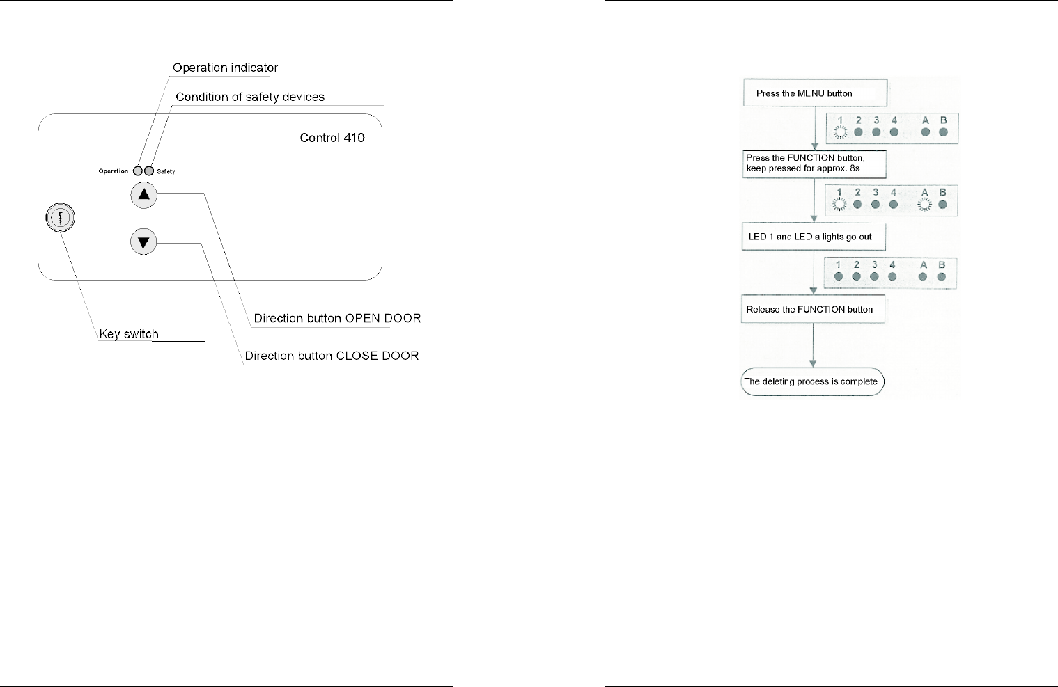
2.2 Operating and indicator elements . . . . . . . . . . . . . . . . . . . . . . .36
2.3 Features . . . . . . . . . . . . . . . . . . . . . . . . . . . . . . . . . . . . . . . . . .37
3 Safety instructions . . . . . . . . . . . . . . . . . . . . . . . . . . . . . . . . . . . .38
4 Installation and initial operation . . . . . . . . . . . . . . . . . . . . . . . . .39
4.1 Installation steps . . . . . . . . . . . . . . . . . . . . . . . . . . . . . . . . . . . .39
4.2 Installation advice . . . . . . . . . . . . . . . . . . . . . . . . . . . . . . . . . . .40
4.3 Functional units . . . . . . . . . . . . . . . . . . . . . . . . . . . . . . . . . . . . .41
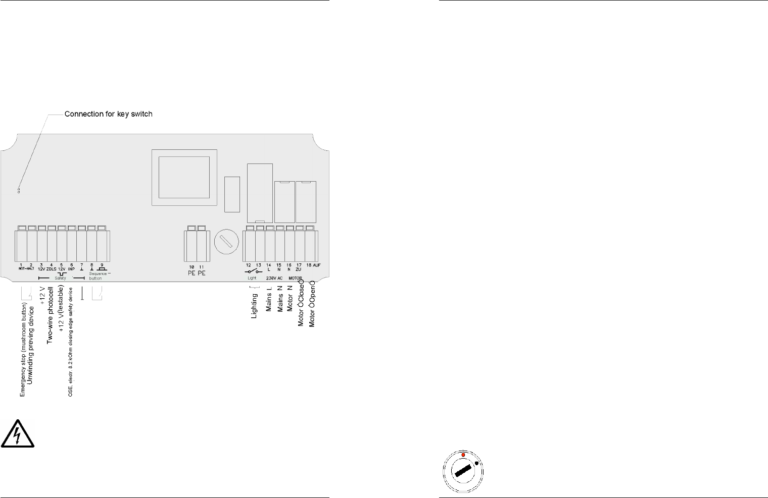
4.4 Command devices . . . . . . . . . . . . . . . . . . . . . . . . . . . . . . . . . . .42
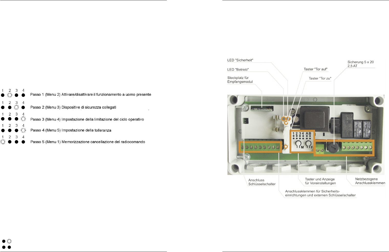
4.4.1 Command buttons on the control unit housing . . . . . . . . . .42
4.4.2 External key switch . . . . . . . . . . . . . . . . . . . . . . . . . . . . . . .42
4.4.3 Wireless remote control . . . . . . . . . . . . . . . . . . . . . . . . . . . .42
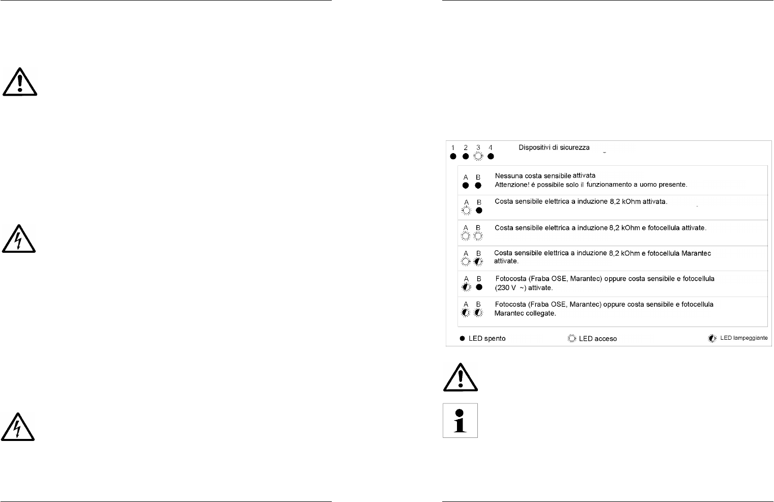
4.5 Safety devices . . . . . . . . . . . . . . . . . . . . . . . . . . . . . . . . . . . . . .43
4.5.1 General . . . . . . . . . . . . . . . . . . . . . . . . . . . . . . . . . . . . . . . . .43
4.5.2 Emergency stop (mushroom button), unwinding prevention .
device . . . . . . . . . . . . . . . . . . . . . . . . . . . . . . . . . . . . . . . . . .43
4.5.3 Internal key switch . . . . . . . . . . . . . . . . . . . . . . . . . . . . . . . .43
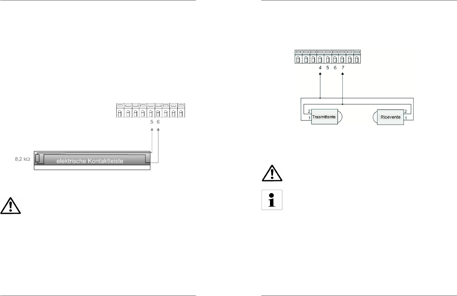
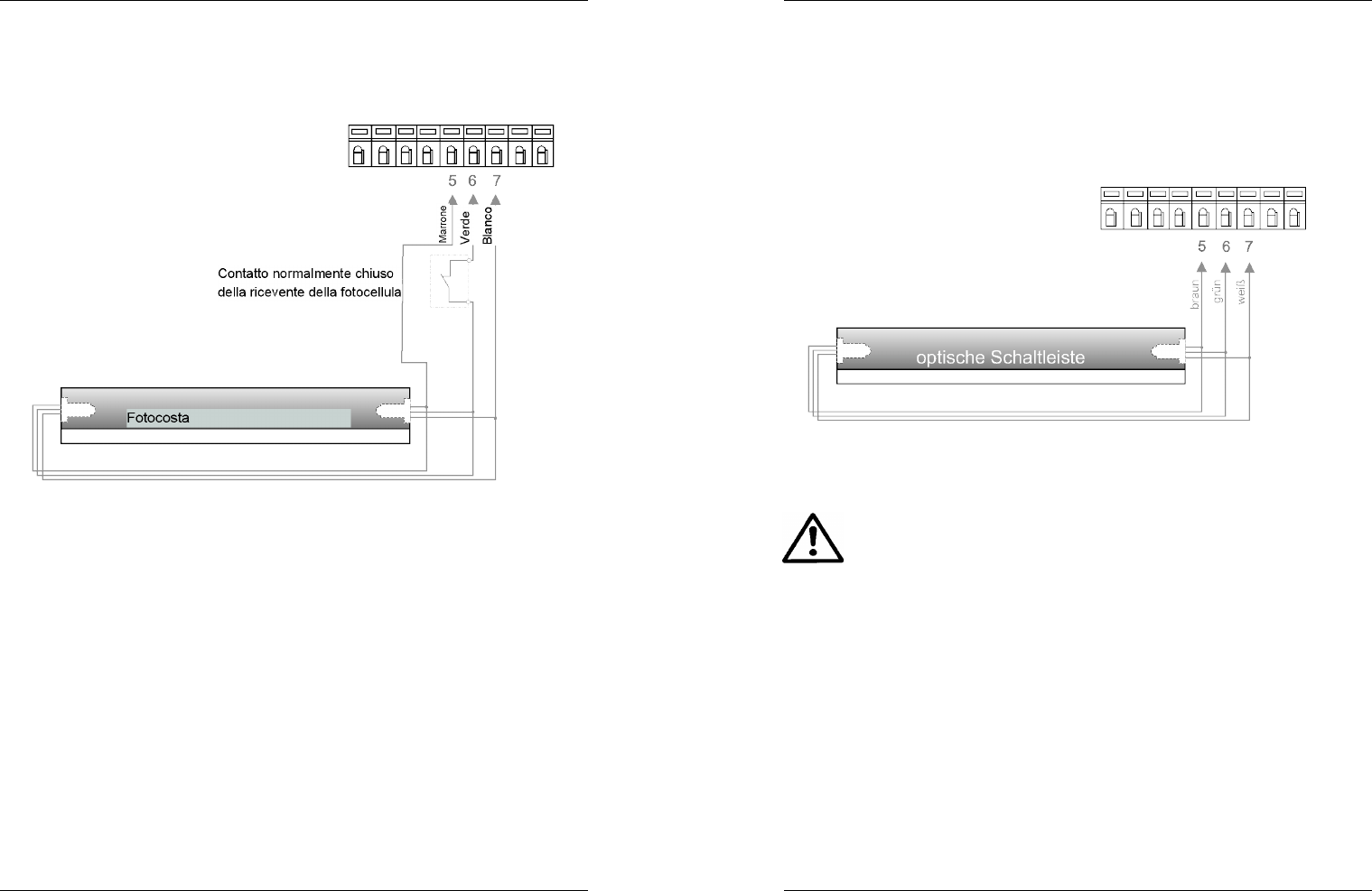
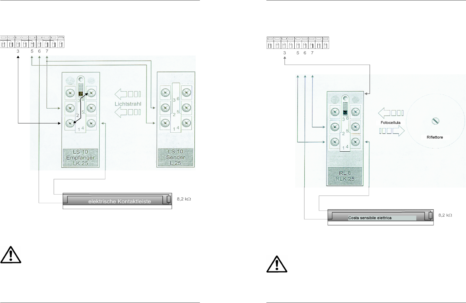
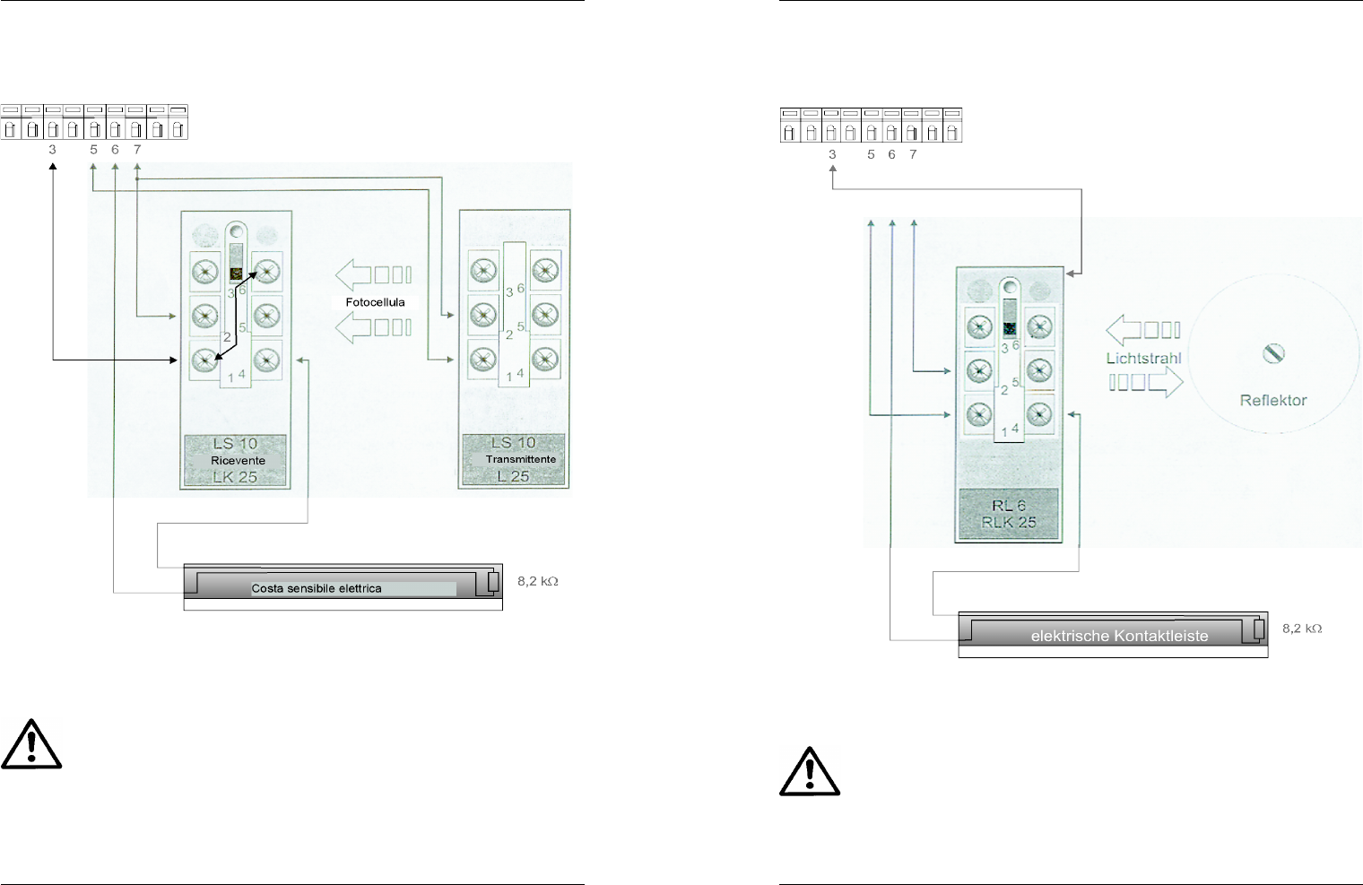
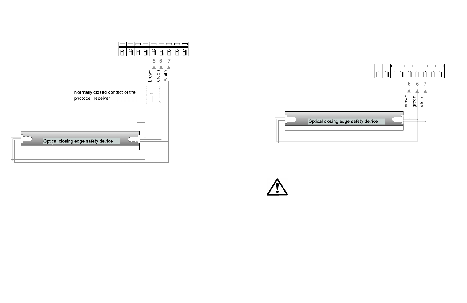
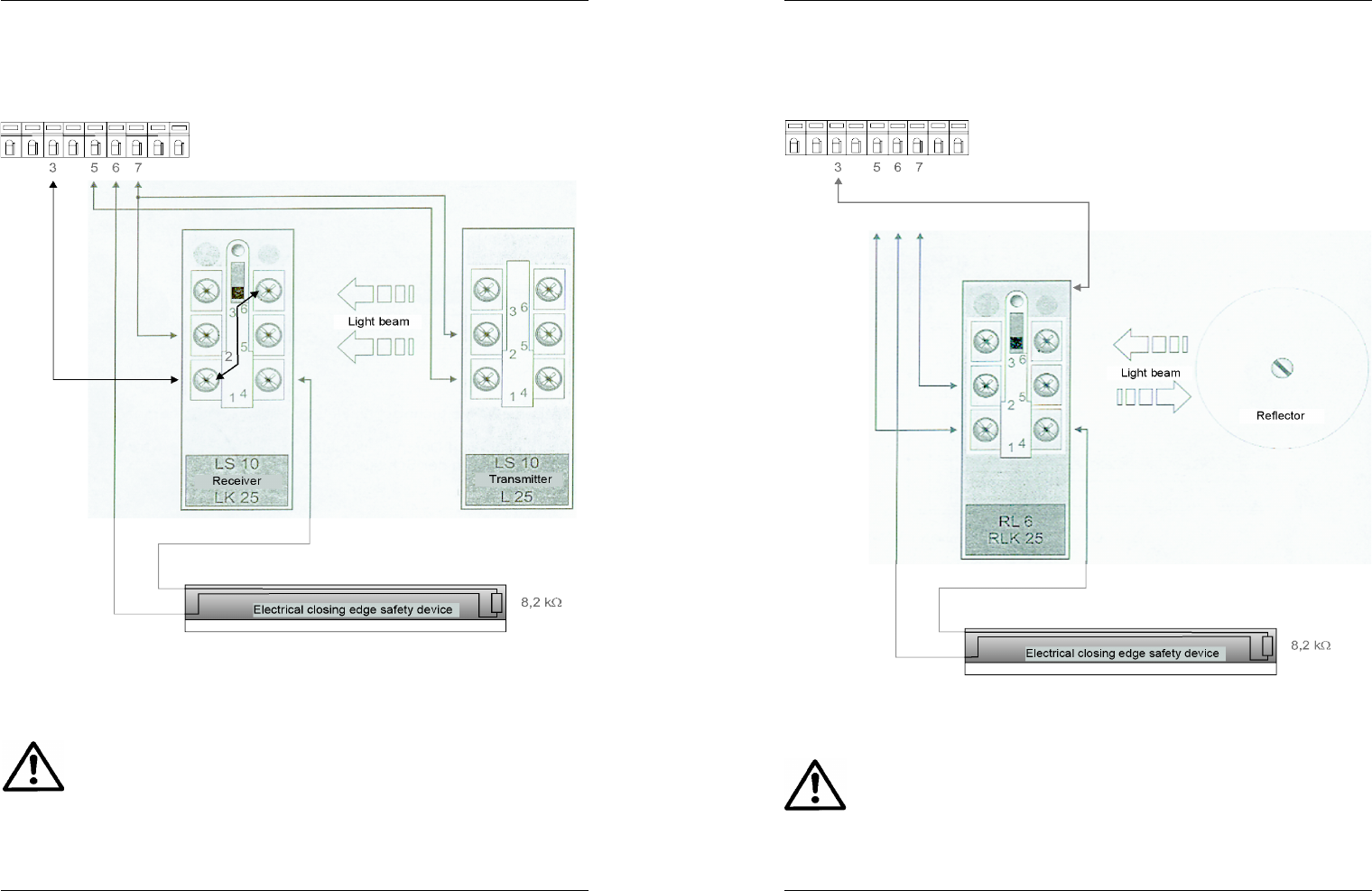
4.5.4 Closing edge safety device . . . . . . . . . . . . . . . . . . . . . . . . .44
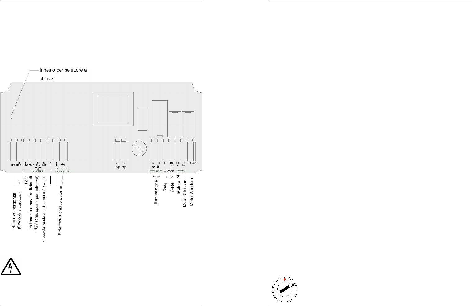
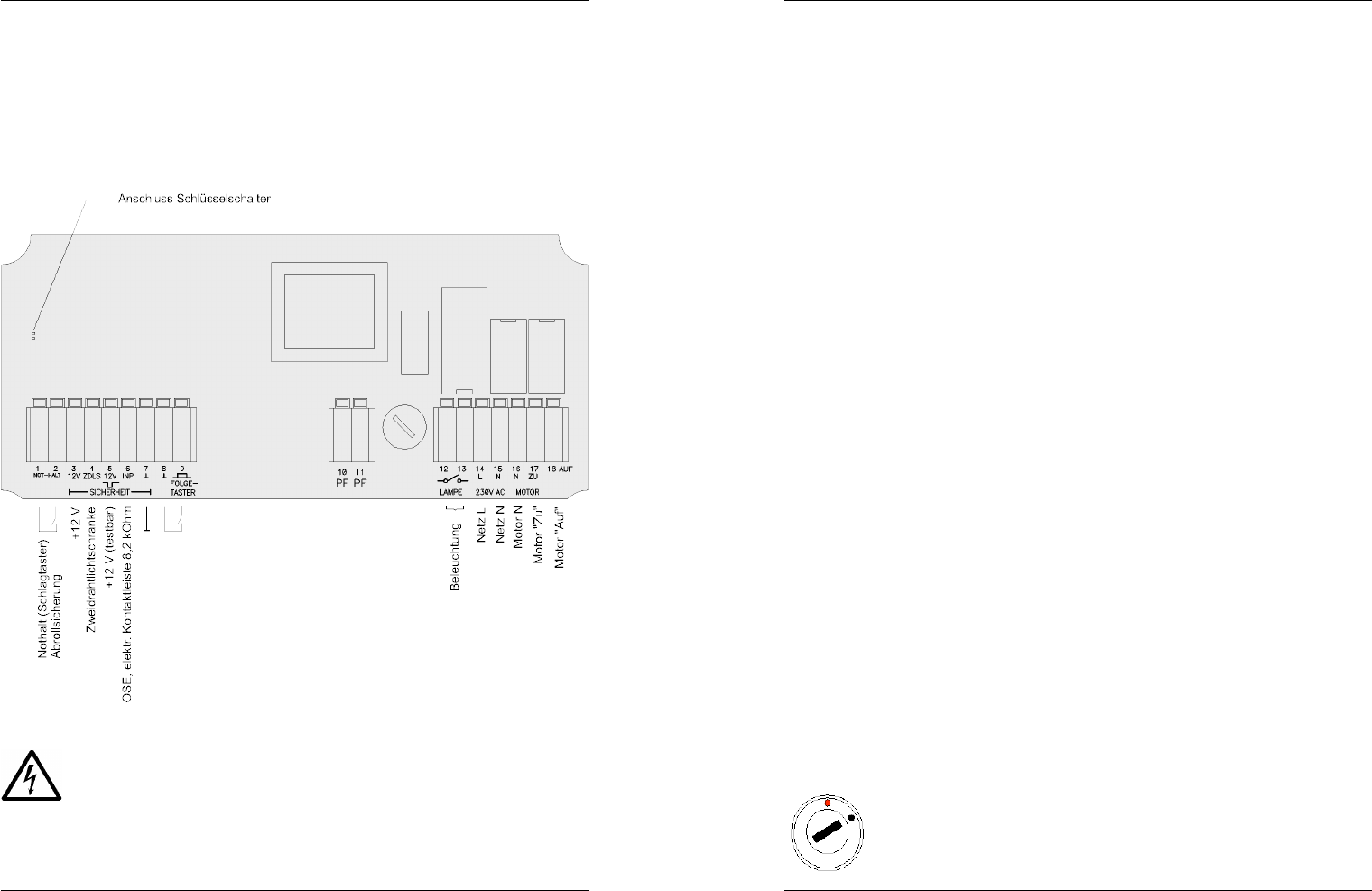
4.6 Anschlusspläne . . . . . . . . . . . . . . . . . . . . . . . . . . . . . . . . . . . . .50
4.6.1 Anschlussplan allgemein . . . . . . . . . . . . . . . . . . . . . . . . . . .50
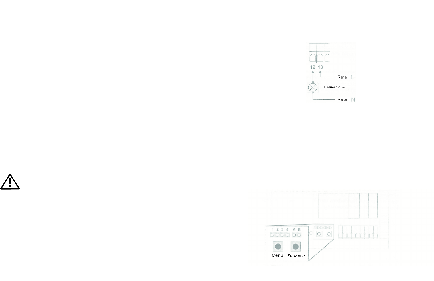
4.6.2 Anschlussplan Beleuchtung . . . . . . . . . . . . . . . . . . . . . . . . .51
4.7 Connection diagram . . . . . . . . . . . . . . . . . . . . . . . . . . . . . . . . .51
4.7.1 General . . . . . . . . . . . . . . . . . . . . . . . . . . . . . . . . . . . . . . . . .51
4.7.2 Deadman mode, activate/deactivate . . . . . . . . . . . . . . . . . .52
4.7.3 Safety devices . . . . . . . . . . . . . . . . . . . . . . . . . . . . . . . . . . .53
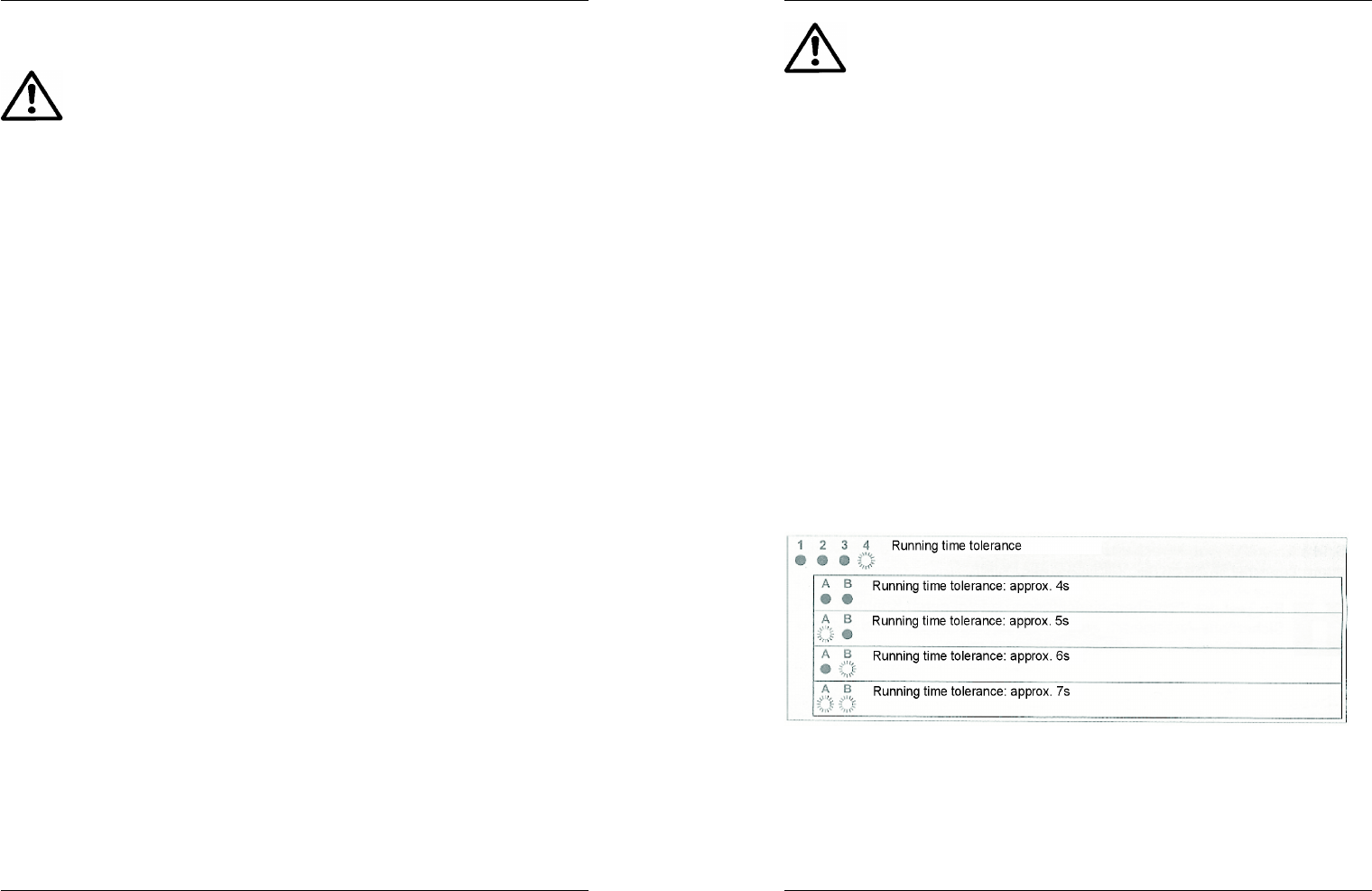
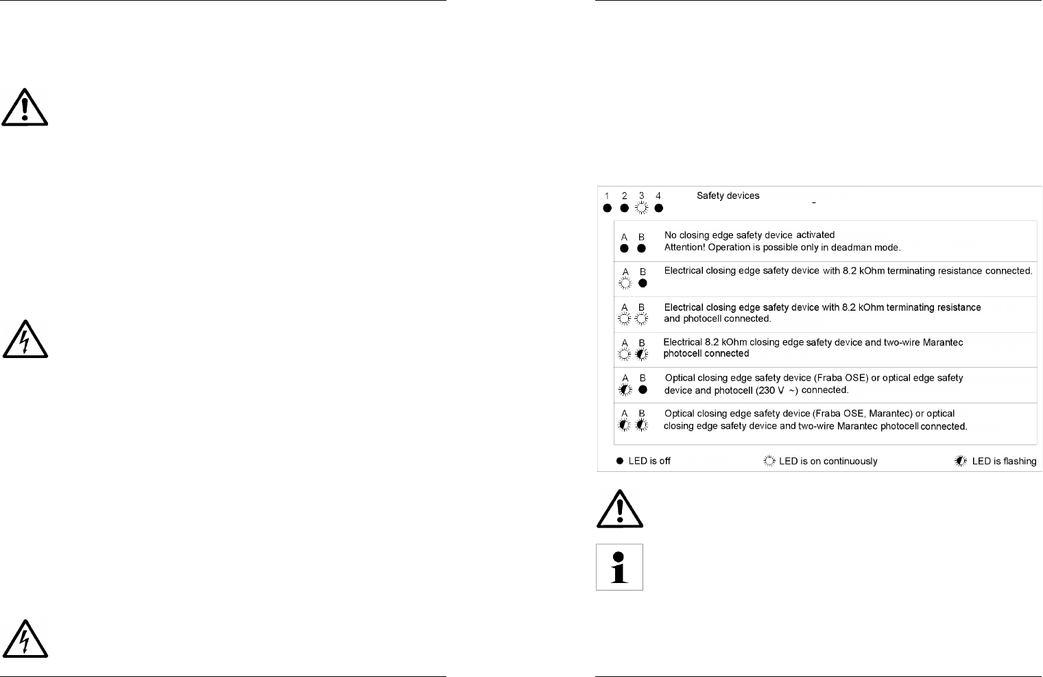
4.7.4 Motor running time and running time tolerance . . . . . . . . . .54
4.7.5 Wireless remote control . . . . . . . . . . . . . . . . . . . . . . . . . . . .56
5 Faults . . . . . . . . . . . . . . . . . . . . . . . . . . . . . . . . . . . . . . . . . . . . . . .58
5.1 General . . . . . . . . . . . . . . . . . . . . . . . . . . . . . . . . . . . . . . . . . . .58
5.2 Resetting the controls (RESET) . . . . . . . . . . . . . . . . . . . . . . . .58
5.3 Fault conditions . . . . . . . . . . . . . . . . . . . . . . . . . . . . . . . . . . . . .59
5.3.1 Safety LED is flashing and one or more other LEDs are on 59
5.3.2 Operation LED and other LEDs are flashing . . . . . . . . . . . .59
6 Standards and regulations . . . . . . . . . . . . . . . . . . . . . . . . . . . . .60
7 Technical data . . . . . . . . . . . . . . . . . . . . . . . . . . . . . . . . . . . . . . . .61
34
Operating instructions for Control 410
General
1 General
These operating instructions are aimed at assisting skilled fitters in the
installation, adjustment and operational start-up of the roller shutter controls.
The user can, of course, also read through the relevant chapters if any
questions should arise regarding the operation of the equipment, for example.
Changes to the settings or wiring, however, may be carried out only by a
skilled fitter.Die Anleitung ist so aufzubewahren, dass diese im Fall eines
Eingriffs durch die Fachkraft jederzeit verfügbar ist.
These instructions must be kept in a safe place where the fitter can access
them at all times for maintenance or inspection purposes.
In addition to these instructions, the relevant standards and regulations
referred to in Chapter 6 (page 30) must also be observed.
Various symbols are used throughout these instructions.
The meaning of these symbols is as follows:
Advice, general information
Hazard due to electric current
General warning
We accept no liability for technical changes.
59
Operating instructions for Control 410
Faults
5.3 Fault conditions
5.3.1 Safety LED is flashing and one or more
of the other LEDs are on
The motor is defective or consumes too much power
It may be possible to operate the door in deadman mode. In
deadman mode, the door is operated by pressing the buttons on the control
unit housing. These must first be enabled via the key switch. Proper operation
can no longer be assured, however. The fitter responsible for the equipment
must be notified!
Motor running time exceeded, door is stiff or jams, curtain
slats are frozen, limit switch is defective
It may be possible to operate the door in deadman mode. The external key
switch or the buttons on the control unit housing are used to operate the door
in deadman mode. These must first be enabled, however, by switching the
key switch on the control unit. Proper operation can no longer be guaranteed,
however. It may be possible to cancel the fault condition by switching off the
control unit. The fitter responsible for the equipment must be notified!
Safety device defective
After the fault has been eliminated or remedied, this fault
condition will be cancelled automatically, since testing of the safety devices is
carried out every two minutes. While this fault condition persists,
press-and-release operation in the OPEN direction is still possible via all
command devices. Movement in the CLOSE direction is only possible in
deadman mode.
5.3.2 Operation LED and other LEDs are flashing:
This fault message indicates a fault in the electronics. In this case, reset the
controls, as described in Chapter 5.2.1. If this does not clear the fault, restore
the controls to their default settings, as described in Chapter 5.2.2. If the
problem still isn't solved, call the fitter responsible for the equipment.
After restoring the default values, all the settings (safety settings,
running time measurements, and transmitter settings, etc.) must
be reprogrammed.
58
Operating instructions for Control 410
Faults
5 Faults
5.1 General
The Control 410 door operator control unit incorporates various safety
features to prevent hazardous situations from arising during operation.
The photocell, the closing edge safety device and the motor running time are
all monitored, for example, and internal checks are carried out.
If a fault is detected, the control unit switches to fault mode. The outward
indication of this is a flashing Safety LED and/or Operation LED. The LEDs
inside the control unit give more specific information regarding the fault. The
overview in Chapter 5.3 describes the possible faults.
Depending on the type of fault, certain door movements can no longer be
operated via press-and-release. The door can then be moved only by keeping
one of the buttons on the housing of the control unit pressed or by keeping
the external key switch turned on. The buttons must first be enabled using the
integrated key switch on the control unit. The buttons must first be enabled
using the key switch. As soon as you release the direction button, the door
will stop immediately. This operating mode has priority over all safety devices.
Since in deadman mode the safety devices (closing edge safety
device and photocell) have no effect, the user may only operate
the door if he/she has a clear view of the door.
5.2 Resetting the controls
5.2.1 RESET
Resetting the controls returns the system to normal operating mode. All the
settings and transmitter programming information remain intact.
To reset the controls, disconnect the control unit from the power supply for at
least three seconds (unplug the mains plug, or remove the fuse, for instance).
5.2.2 Activate the default settings
If you restore the controls to their original (ex factory) state, all
settings (safety settings, running time measurements, transmitter
programming information) will be lost.
1. Disconnect the power supply.
2. Press the FUNCTION button and keep it pressed while you switch the
power back on, and
3. continue to hold the FUNCTION button pressed
(for approximately 10 seconds) until the Operation LED lights up.
35
Product description
Operating instructions for Control 410
2 Product description
2.1 Scope of supply
The following parts are included in the package with the roller shutter controls
and this instruction leaflet:
- Mains connection lead, 3 x 0.75 mm², external diameter approx. 6.5 mm,
with safety plug
- 5 cable glands, M16 x 1.5
- 5 plug screws, M16 x 1.5
- 4 screw caps for the control unit housing
- 4 screws, 4 x 35 mm, for wall mounting
- 4 dowels, S6
- Spare fuse, 2.5 A delay fuse, 5 x 20
- 2 keys
Before you start installing the device, check that all the parts are present.
36
Operating instructions for Control 410
Product description
2.2 Operating and indicator elements
Operation indicator: - lights up green, if the control unit is switched on.
- flashes if there is an internal fault.
Safety indicator: - light goes out if all the safety devices that are
connected are ready for operation and have not
been triggered.
- lights up red if a safety device has been triggered.
- flashes in the event of faults
Figure 2-1: Operating and indicator elements
57
Operating instructions for Control 410
All 28 transmitters can be deleted from the memory completely by following
the procedure below:
Installation and initial operation
56
Operating instructions for Control 410
Installation and initial operation
4.7.5 Wireless remote control
If deadman mode has been activated, it is not possible to operate the door by
remote control.
A maximum of 28 wireless hand transmitters or wireless wall-mounted
transmitters can be used in conjunction with the roller shutter control unit.
Each of these transmitters must be programmed into the controls as follows.
If deadman mode has been activated, no transmitters can be
programmed in and, for safety reasons, the stored data for all
transmitters that have already been programmed will be deleted.
Programming hand transmitters (Step 5)
The programming process is carried out as shown in the following flow chart:
37
Product description
Operating instructions for Control 410
2.3 Features
The Control 410 roller shutter control unit can be used to operate tubular
drives with integrated travel cut-out systems and a power consumption of up
to 600 VA. The areas of application are privately and commercially used
garage doors and gateways. If used with roll-up grilles or other doors with
openings or penetrations, the controls may be operated only in deadman
mode (see Chapter 4.7.2)!
Drive commands can be given using the integrated direction buttons, an
externally connected key switch (if fitted), or a wireless hand transmitter.
The operating parameters are set via a menu system and 6 LEDs inside the
housing. Two of these LEDs are visible from the outside and indicate the most
important operational states.
38
Operating instructions for Control 410
Safety instructions
3 Safety instructions
The Control 410 roller shutter control unit is manufactured using
the most up-to-date technology and methods, and complies with
the generally recognised safety regulations. Nevertheless, hazard
situations cannot be ruled out. In order to minimise this risk,
several instructions must be followed:
- Read the operating instructions carefully before installing or starting up the
equipment.
- The controls may only be used with roll-up grilles or other doors with ope-
nings or penetrations if they are operated in deadman mode!
- Suitable measures must be taken to ensure that children and unauthorised
persons cannot use the controls.
- The roller shutter controls may only be set in operation if they are in
perfect condition.
- Only properly qualified and trained persons are permitted to install
the controls and set the parameters.
- The relevant standards and guidelines must be observed without fail when
installing the equipment.
- Always disconnect the control unit from the mains before any wiring work
is undertaken.
- If safety devices have been connected, these may not be bridged or
overridden by any other measures.
- The safety devices must be checked every 6 months, or at least every 12
months, to ensure that they function properly.
- Unauthorised modifications, such as drilling additional holes in
the housing, or using other types of fuse, etc., are not permitted.
- If faults occur, or the equipment is damaged, the responsible fitter must be
notified.
- Do not allow children to play with the controls.
- Keep the wireless hand transmitter away from children.
- The housing should be cleaned using a moist cloth. The use of solvents
that corrode the housing is not permitted.
55
Operating instructions for Control 410
Attention! During the measurement procedure (two to three
automatic door runs), do not issue any drive commands (via the
buttons or hand transmitter, for example). Furthermore, you must
ensure that the safety devices cannot be triggered during the
measurement procedure. Failure to comply with these instruc-
tions will result in the measurement procedure being aborted
before completion.
Running time tolerance (Step 4)
The running time of the door fluctuates within certain limits. These fluctuations
can be caused by seasonal changes, differences in temperature, or other
external influences. Since the exact motor running time is stored in the
memory of the roller shutter controls during installation of the door, a certain
fluctuation range must be allowed; otherwise the running time could easily be
exceeded as a result of the above-mentioned influences. If the running time is
exceeded, the roller shutter controls switch to a fault mode (see Chapter. 5).
The fitter must estimate the tolerance value required for the door in question.
The possible values are: 4s, 5s, 6s, and 7s.
To set the tolerance value, select Menu 4 by pressing the "Menu" button 4
times (LED 4 lights up). Press the "FUNCTION" button (hold it pressed for
longer than 1.6 seconds) to select the desired tolerance value:
When the value has been set, press the "Menu" button to leave the menu.
Installation and initial operation
54
Operating instructions for Control 410
Installation and initial operation
4.7.4 Motor running time and running time tolerance
Programming the running time (Step 3)
After installing a door, the exact running time for the opening and closing
processes must be saved in the roller shutter controls. This is essential for
operational reliability. If the motors internal limit switches are defective, for
example, the motor will not switch off and this will result in irreversible mecha-
nical damage to the door system. It could also result in injuries to persons.
If the controls are operated in deadman mode, the running time must be
programmed by carrying out door runs in deadman mode. Otherwise,
the controls carry out a programming run automatically. The starting position
of the door is irrelevant for the measuring procedure. After the procedure has
been completed (after two or three door movements), the door stops at the
upper end position.
Follow the instructions in the flow chart below, starting when the door is
stationary:
39
Installation and initial operation
Operating instructions for Control 410
4 Installation and initial operation
4.1 Installation steps
Before the control unit can be set in operation, the steps listed below must be
followed in the order specified, as a minimum requirement. The door can then
be operated from the control unit housing or using a wireless hand transmitter.
Any additional equipment can be installed afterwards, as required. This does
not affect the basic functions, however.
If during installation or initial operation the control unit should
switch to fault mode (the safety LED or operation LED starts
to flash), because the settings were not adjusted correctly, for
example, then the system can be returned to operating mode
(see Chapter 5.2, page 28, on resetting) by disconnecting the
control unit from the mains for at least three seconds (pull out the
mains plug or remove the fuse, for instance).
Step Description Reference
1 Install the control unit Chapter 4.2
2 Set the end of travel positions of the motor Motor manufacturer's instructions
3
Connect the motor to the control unit
Connect the control unit to the mains
Chapter 4.2
Chapter 4.6
4
Select the operating mode (activate/deactivate
deadman mode)
Chapter 4.7.2
5
Connect the required safety devices (unwinding
prevention device, OSE, 8.2 kohm closing edge
safety device, photocell, etc...)
Safety device instructions
Chapter 4.5
6
In the menu, activate the closing edge safety
device and, if applicable, the photocell.
Chapter 4.7.3
7
Test the safety devices to make sure that they
operate properly
Chapter 4.7.3
8
Program the door running time into the control
unit and set the running time tolerancen
Chapter 4.7 .4
9 Program the hand transmitter(s) Chapter 4.7.5
40
Operating instructions for Control 410
Installation and initial operation
4.2 Installation advice
The roller shutter controls are fixed to the wall with four screws (included in
the package).
Attention! When choosing where to install the control unit, ensure
that the person operating the integrated command buttons always
has an unobstructed view of the door. Suitable measures must be
taken to ensure that children and unauthorised persons cannot use
the controls.
The control unit must be mounted at a height of at least 1.50 m, but no more
than 1.90 m from the floor. It is essential that the control unit be mounted at a
safe distance from any moving parts. The cable glands must always face
downwards!
All the connections inside the control unit housing have removable screw ter-
minals for rigid or flexible cables with cross-sections up to 2.5 mm² or for
stranded wires with end sleeves up to 1.5 mm² in cross-section.
The power supply is single-phase from the 230 V mains (L, N, PE).
Attention! All-pole disconnection from the mains must be possible
at all times. This can be achieved by installing a mains switch, or a
plug and socket connection, for example. Permanently wired mains
connections, such as recess-mounted sockets, are not permitted.
For installations in the commercial sector, the mains cut-off device must be
secured to prevent the system from being switched on again by unauthorised
persons. If a mains cable with a plug is used, the plug must still be easily
accessible after the control unit has been installed. The socket itself must
always be earthed in accordance with VDE0100.
The 230 V motor of the door operator to be controlled must have connections
for the "open" and "close" directions, a neutral conductor and a protective
earth conductor. The connection diagram (Figure 4.8 on page 20) shows how
the connections to the terminals are to be made.
The motor connections for the OPEN, CLOSE, and neutral conductor
must always be connected directly to the control unit
The yard lighting or garage lighting is connected with a switch-off delay of
three minutes (see page 21, "Connection of lighting").
Attention! External fuse protection must be provided for the
lighting circuit, since none is provided in the control unit itself.
4.7.3 Safety devices (Step 2)
Any safety devices, such as an OSE optical closing edge safety device,
electrical closing edge safety, or photocell, must be recognised by the
controls. To make these known to the controls, call up Menu 3 by pressing the
"Menu" button three times. Use the "Function" button to scroll through the
following options:
The electrical connection of the safety devices is described in Chapter 4.5.
When the appropriate setting for your installation has been selected, press
the "Menu" button twice to leave the menu.
If deadman mode is activated, the safety elements will not be
evaluated by the controls.
The safety devices are tested by checking the safety indicator on
the housing of the control unit: the indicator light should go out
when a safety device is triggered.
Installation and initial operation
53
Operating instructions for Control 410
4.7.2 Deadman mode, activate/deactivate (Step 1)
In deadman mode, a roll-up grille, for example, can only be operated by using
the "Open door"/"Close door" direction buttons or via the "Button" input.
The key switch must be set to the black position. When operating the door in
deadman mode, the safety devices connected to the control unit are not
evaluated.
Remote control is not possible. For safety reasons, all the wireless transmitter
program data is deleted when deadman mode is activated, and wireless
transmitters cannot be programmed in.
To activate (the safety LED flashes slowly) or deactivate deadman mode,
press the "Menu" button twice and then press the "Function" button.
52
Operating instructions for Control 410
Installation and initial operation
The "Menu" button is used to select the menus (1 to 4). The "Function" button
is used to select a value or a function (A, B) in a menu.
To call up the menu required, press the "Menu" button repeatedly until the
corresponding LED lights up. Within the menu, parameters are selected in the
same manner. After the last menu item, the control unit returns to the normal
operating state.
We recommend that you follow the sequence described in Chapter 4.1. This
means that the safety devices must always be connected and configured first,
unless the controls are to be used only in deadman mode. The motor running
time can then be programmed and the running time tolerance can be set. The
programming of wireless hand transmitters is the final step in
the configuration process.
Deadman mode activated
A
B
Deadman mode deactivated
41
Installation and initial operation
Operating instructions for Control 410
4.3 Functional units
The following picture shows the circuit board inside the housing. You will need
access to this when installing and configuring the control unit before initial
operation.
Figure 4-1: Functional elements
SAFETY LED
OPERATION LED
OPEN DOOR
button
CLOSE DOOR
button
2.5 AT
Fue 5 x 20
Mains related
connection terminals
Buttons and indicators
for setting the parameters
Connection terminals for safety
Key switch
connection
devices and command devices
reception module
Port for connecting
42
Operating instructions for Control 410
Installation and initial operation
4.4 Command devices
4.4.1 Command buttons on the housing of the control
unit
In normal operating mode, pressing one of the direction buttons on
the housing of the control unit will start the door moving automatically in the
corresponding direction. Press the other button to stop the movement of the
door.
In certain fault situations, where a safety device has been triggered or is
defective, for example, the door can only be moved up or down in "deadman
mode". This means that the door continues to move only as long as one of
the direction buttons on the control unit housing is held pressed or the
external key switch is switched on. As soon as the button is released, the
door immediately stops moving. In this case, the direction buttons can only be
used if they have been enabled by turning the key switch on at the control
unit. In this scenario, all other command devices are deactivated.
If the unwinding prevention device is triggered, no door movements at all are
possible, not even in deadman mode.
4.4.2 External key switch
The OPEN > STOP > CLOSE > STOP > ... commands are given via the input
connection for an external key switch, at terminals 8 and 9. This connection
must be made as a normally open contact.
Attention! Since deadman operation is possible via this input, no
other command devices may be connected to it.
4.4.3 Wireless remote control
The optimal method of controlling the door is to use a wireless hand transmit-
ter. The radio receiver module already built in to the control unit makes this
possible.
The control unit is designed for one-button operation. When the transmission
button is pressed the first time, the door moves in one direction. When
pressed a second time, the door stops. When pressed a third time, the door
moves in the opposite direction (OPEN > STOP > CLOSE > STOP > OPEN >
STOP > ...). The button code of the hand transmitter must first be program-
med into the control unit. Please see Chapter 4.7.5 on page 26 for details.
51
Installation and initial operation
Operating instructions for Control 410
4.6.2 Lighting connection diagram
The connection for the lighting is provided as a potential-free normally-open
contact within the control system, i.e. there is no voltage here. The connection
must be made as follows:
4.7 Default settings
4.7.1 General
Before initial operation, the correct operating parameters must be set in
the Control 410 (steps 1-4, see page 22). If these parameters are not set,
proper and safe operation of the control unit cannot be guaranteed.
The settings are made via a menu system and six LED indicators, each with
its own associated button, inside the control unit. All the settings are saved in
the memory even if there is a power failure.
Figure 4-9: Connection of lighting
Figure 4-10: Settings panel
50
Operating instructions for Control 410
Installation and initial operation
4.6 Connection diagram
4.6.1 General connection diagram
Figure 4-8 shows the assignment of the individual terminals. All safety devices
and command devices are connected to the terminals on the left-hand side.
The terminals on the right-hand side are for elements that have a connection
to the 230 V mains supply.
Attention! The motor connections OPEN, CLOSE and neutral
conductor must always be connected directly to the control
unit terminals. If the neutral conductor is connected directly
to the motor from the mains supply, the control unit will be
destroyed!
Figure 4-8: Connection diagram
External key switch
43
Operating instructions for Control 410
Installation and initial operation
4.5 Safety devices
4.5.1 General
Specific safety features are required depending on the type of door, the
application, and the user group. In order to determine the correct combination
of safety devices for your particular case, you may need to consult the
regulations listed in Chapter 6. These regulations must be adhered to without
fail. It is the responsibility of the fitter to install the safety devices correctly,
configure the controls accordingly, and ensure that the safety devices are ser-
viced at the specified service intervals. Servicing is usually carried out every
six months. Never allow the safety devices to be overridden or to be rendered
ineffective by any other means.
The status of the safety devices in general is shown by the red safety indica-
tor (see Figure 2-1) on the housing of the control unit:
"Safety" off: all safety devices OK and not triggered.
"Safety" on: at least one safety device has been triggered.
"Safety" flashing: there is a fault (see Chapter 5).
Naturally, the indicators can only indicate the status of the safety devices
correctly if the control unit has been properly configured (Chapter. 4.7).
4.5.2 Emergency stop (mushroom button), unwinding
prevention device
In the normal operating state, there must be a connection between terminals
1 and 2. If this connection is broken, no door movements will be possible,
even in deadman mode. A moving door will stop immediately if this connection
is broken. Amongst other things, this input allows the connection of an
unwinding prevention device and possibly other normally closed contacts
(such as an emergency stop button). If this input is not used, a bridge must
be inserted.
4.5.3 Internal key switch
If a fault occurs, the door can be driven in the CLOSE direction only in
deadman mode (operation without press-and-release), by operating the
direction buttons or the external key switch. For applications in public areas
(including private garage doors), the law requires, in addition to deadman
operation, that the controls be secured in order to prevent operation by
unauthorised persons.
When switched to the black position, the integrated key switch
enables the direction buttons and the external key switch to be
used to operate the door in deadman mode. It may only be
switched by trained persons. .
44
Operating instructions for Control 410
Installation and initial operation
4.5.4 Closing edge safety device
Various types of closing edge safety device can be used to provide protection
for the closing edge of a door.
- Electromechanical closing edge safety device with a connected resistance
of 8.2 kohm
- Optical closing edge safety device (Marantec / Fraba "OSE")
Electromechanical closing edge safety device, 8.2 kohm
Figure 4-2 shows how to connect a closing edge safety device with a
connected resistance of 8.2 kohm to the system. (Meets the requirements of
EN ISO 13849-1, Category 2/Performance Level "c".).
Attention! Design features must be incorporated into the door
system to prevent the closing edge safety device from being
triggered when it reaches the end of travel position at the bottom.
Figure 4-2: Connection of an 8.2 kohm electrical closing edge safety device
49
Installation and initial operation
Operating instructions for Control 410
Two-wire photocell, Marantec
Attention! Check that the poles are connected the right way
round.
Note: The connection of a closing edge safety device is
absolutely necessary!
Figure 4-7: Connection of two-wire photocell, Marantec
48
Operating instructions for Control 410
Installation and initial operation
Photocell (230 V ~) and optical closing edge safety device (Fraba OSE)
(Meets the requirements of EN ISO 13849-1, Category 2/Performance Level
"c".).
Figure 4-6: Connection of photocell (230 V ~) and OSE
45
Operating instructions for Control 410
Installation and initial operation
Optical closing edge safety device (Marantec / Fraba OSE)
The OSE is an active closing edge safety device that requires a supply
voltage of 12 V DC in order to operate. Terminal 5 provides this supply
voltage. (Meets the requirements of EN ISO 13849-1, Category
2/Performance Level "c".).
Attention! Design features must be incorporated into the door
system to prevent the closing edge safety device from being
triggered when it reaches the end of travel position at the bottom.
Figure 4-3: Connection of closing edge safety device
46
Operating instructions for Control 410
Installation and initial operation
Visolux photocell (12 V) and electrical closing edge safety device
(8.2 kohm)
(Meets the requirements of EN ISO 13849-1, Category 2/Performance Level
"c".).
Attention! In the photocell receiver, LK 25, a bridge must be
fitted between terminal 1 and terminal 6. Slide the light-dark
switch down to the bottom position.
Figure 4-4: Connection of Visolux photocell (12 V) and electrical 8.2 kohm closing edge safety device
47
Operating instructions for Control 410
Installation and initial operation
Visolux photocell (12 V) and electrical closing edge safety device
(8.2 kohm)
(Meets the requirements of EN ISO 13849-1, Category 2/Performance Level
"c".).
Attention! Slide the light-dark switch down to the bottom
position.
Figure 4-5: Connection of Visolux photocell (12 V) and electrical 8.2 kohm closing edge safety device
1

Hulp nodig? Stel uw vraag in het forum

Spelregels

Misbruik melden

Gebruikershandleiding.com neemt misbruik van zijn services uitermate serieus. U kunt hieronder aangeven waarom deze vraag ongepast is. Wij controleren de vraag en zonodig wordt deze verwijderd.

Product:

Bijvoorbeeld antisemitische inhoud, racistische inhoud, of materiaal dat gewelddadige fysieke handelingen tot gevolg kan hebben.

Bijvoorbeeld een creditcardnummer, een persoonlijk identificatienummer, of een geheim adres. E-mailadressen en volledige namen worden niet als privégegevens beschouwd.

Spelregels forum

Om tot zinvolle vragen te komen hanteren wij de volgende spelregels:

Belangrijk! Als er een antwoord wordt gegeven op uw vraag, dan is het voor de gever van het antwoord nuttig om te weten als u er wel (of niet) mee geholpen bent! Wij vragen u dus ook te reageren op een antwoord.

Belangrijk! Antwoorden worden ook per e-mail naar abonnees gestuurd. Laat uw emailadres achter op deze site, zodat u op de hoogte blijft. U krijgt dan ook andere vragen en antwoorden te zien.

Abonneren

Abonneer u voor het ontvangen van emails voor uw Marantec Control 410 bij:


U ontvangt een email met instructies om u voor één of beide opties in te schrijven.


Ontvang uw handleiding per email

Vul uw emailadres in en ontvang de handleiding van Marantec Control 410 in de taal/talen: Duits, Engels, Italiaans als bijlage per email.

De handleiding is 7,44 mb groot.


U ontvangt de handleiding per email binnen enkele minuten. Als u geen email heeft ontvangen, dan heeft u waarschijnlijk een verkeerd emailadres ingevuld of is uw mailbox te vol. Daarnaast kan het zijn dat uw internetprovider een maximum heeft aan de grootte per email. Omdat hier een handleiding wordt meegestuurd, kan het voorkomen dat de email groter is dan toegestaan bij uw provider.

Stel vragen via chat aan uw handleiding

Stel uw vraag over deze PDF

Uw handleiding is per email verstuurd. Controleer uw email

Als u niet binnen een kwartier uw email met handleiding ontvangen heeft, kan het zijn dat u een verkeerd emailadres heeft ingevuld of dat uw emailprovider een maximum grootte per email heeft ingesteld die kleiner is dan de grootte van de handleiding.

Er is een email naar u verstuurd om uw inschrijving definitief te maken.

Controleer uw email en volg de aanwijzingen op om uw inschrijving definitief te maken

U heeft geen emailadres opgegeven

Als u de handleiding per email wilt ontvangen, vul dan een geldig emailadres in.

Uw vraag is op deze pagina toegevoegd

Wilt u een email ontvangen bij een antwoord en/of nieuwe vragen? Vul dan hier uw emailadres in.


Info