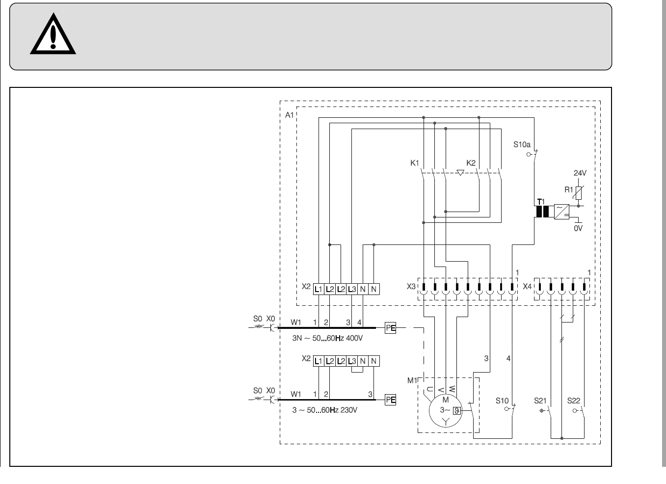
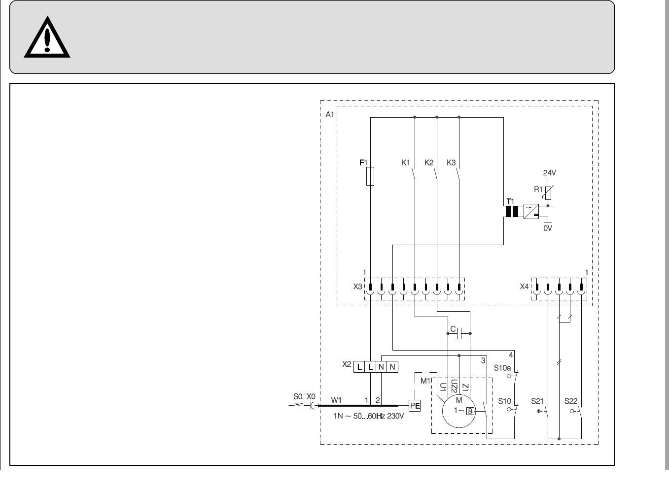
English / Page 13
6. Display functions and programming possibilities
6.1 Summary of display functions and programming
possibilities
Display functions
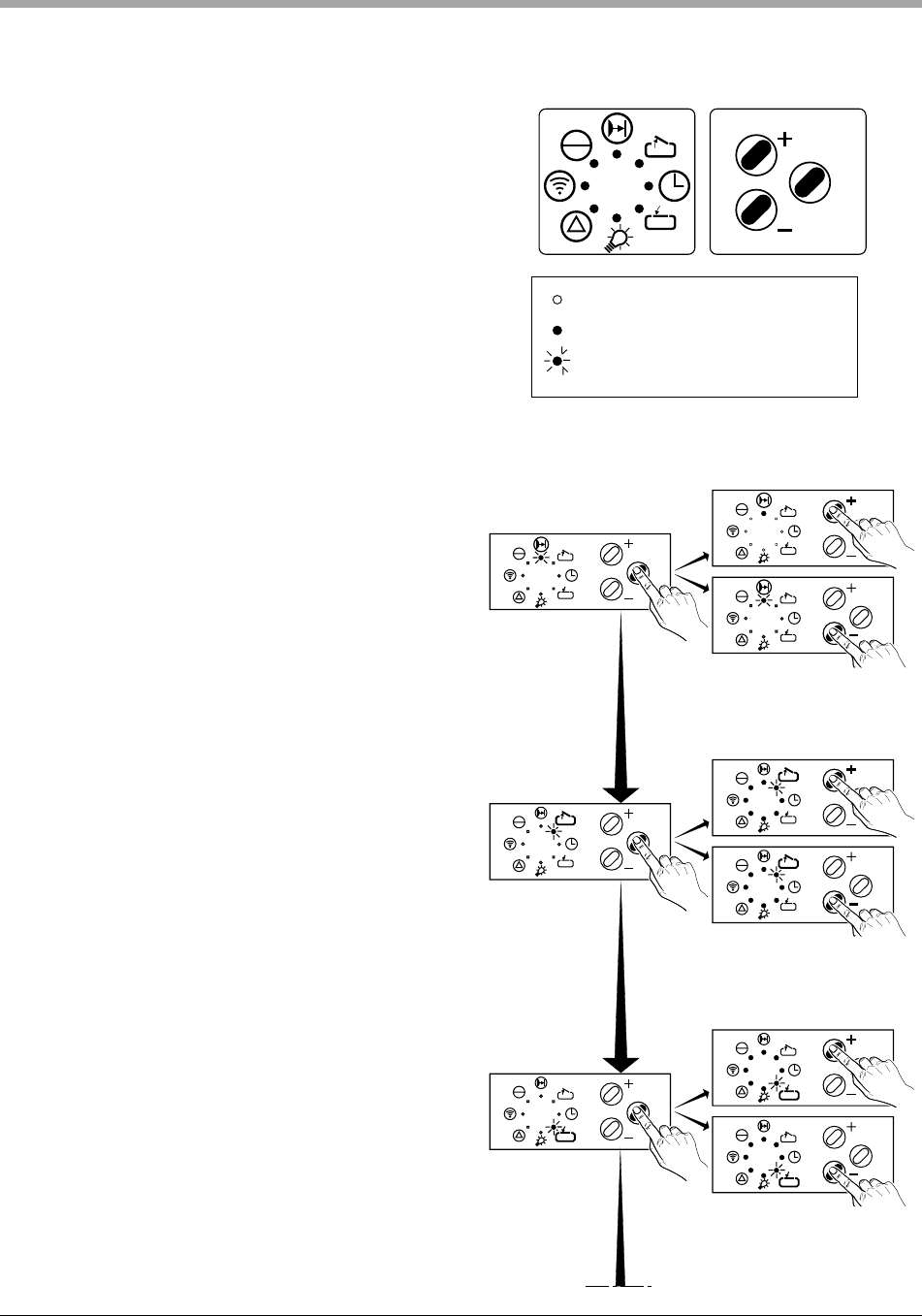
After connecting to mains supply the control unit performs a self-check.
(all control lights light up for approx. 2 sec.).
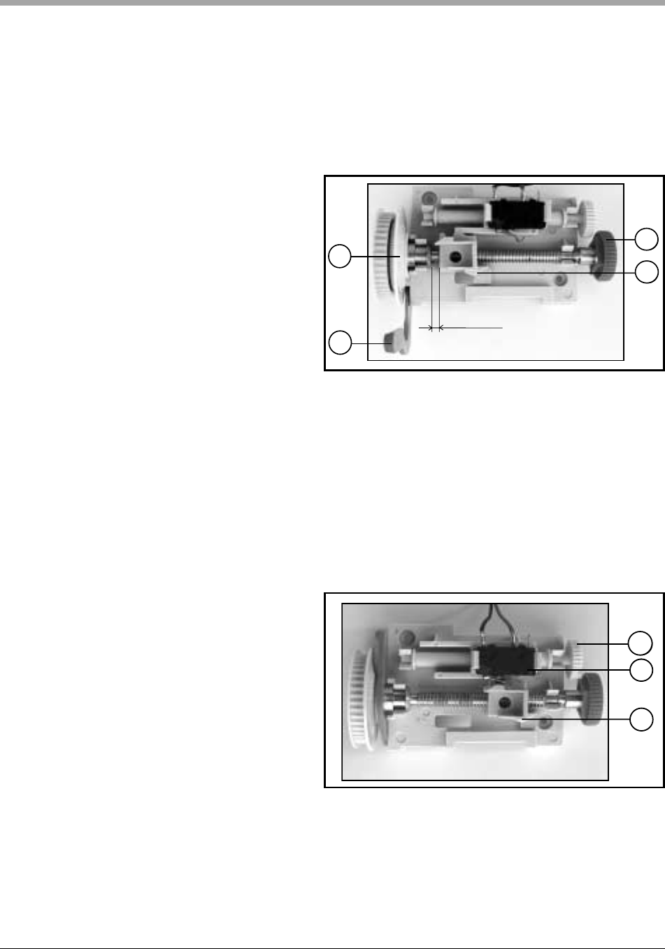
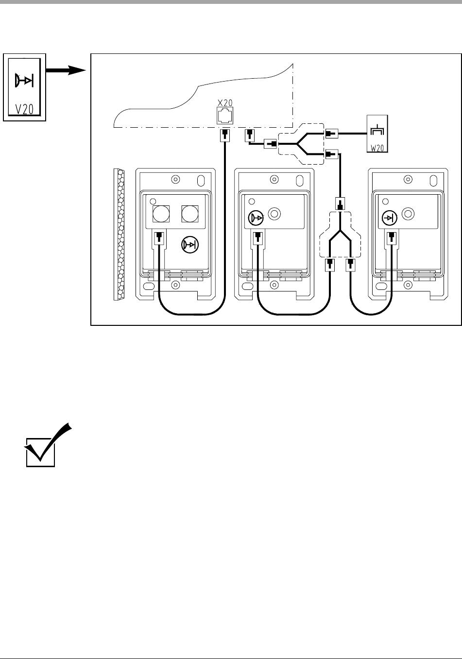
• See fig. 3 / page 5
Error messages
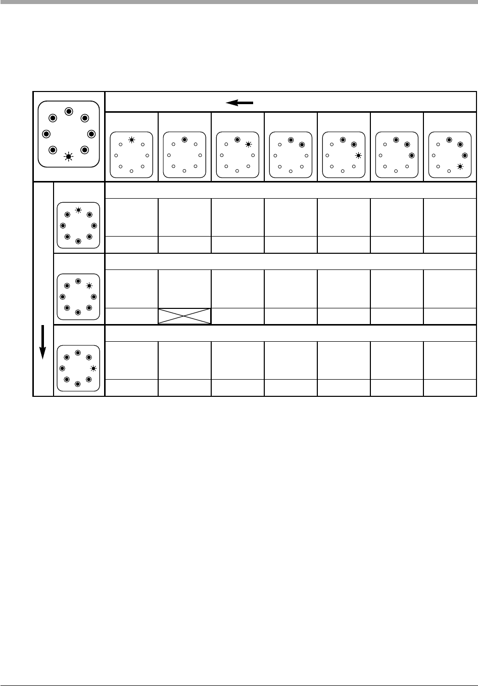
If control light MALFUNCTION (6) lights upt, after shortly pressing button j (10)
the respective error number is indicated (LED's flash irregularly).
The error number is calculated by adding the flashing figures.
• See section 9, error numbers, page 33.
Programming of the operator's basic functions
Press button j (10) longer than 2 sec. The control unit changes from operating
mode to programming mode of basic functions, LED 1 flashes. All other LED's
are glowing. Release button j.
By pressing buttons h (11) or g (12) you can change settings in programming
menu and save with button j. (If button j is actuated without change of
settings by means of buttons h or g, the programming menu is skipped and
the settings remain unchanged.) After last programming menu the programming
of the operator's basic functions is completed, recognizable by all LED's going
out in sequence 8 - 1.
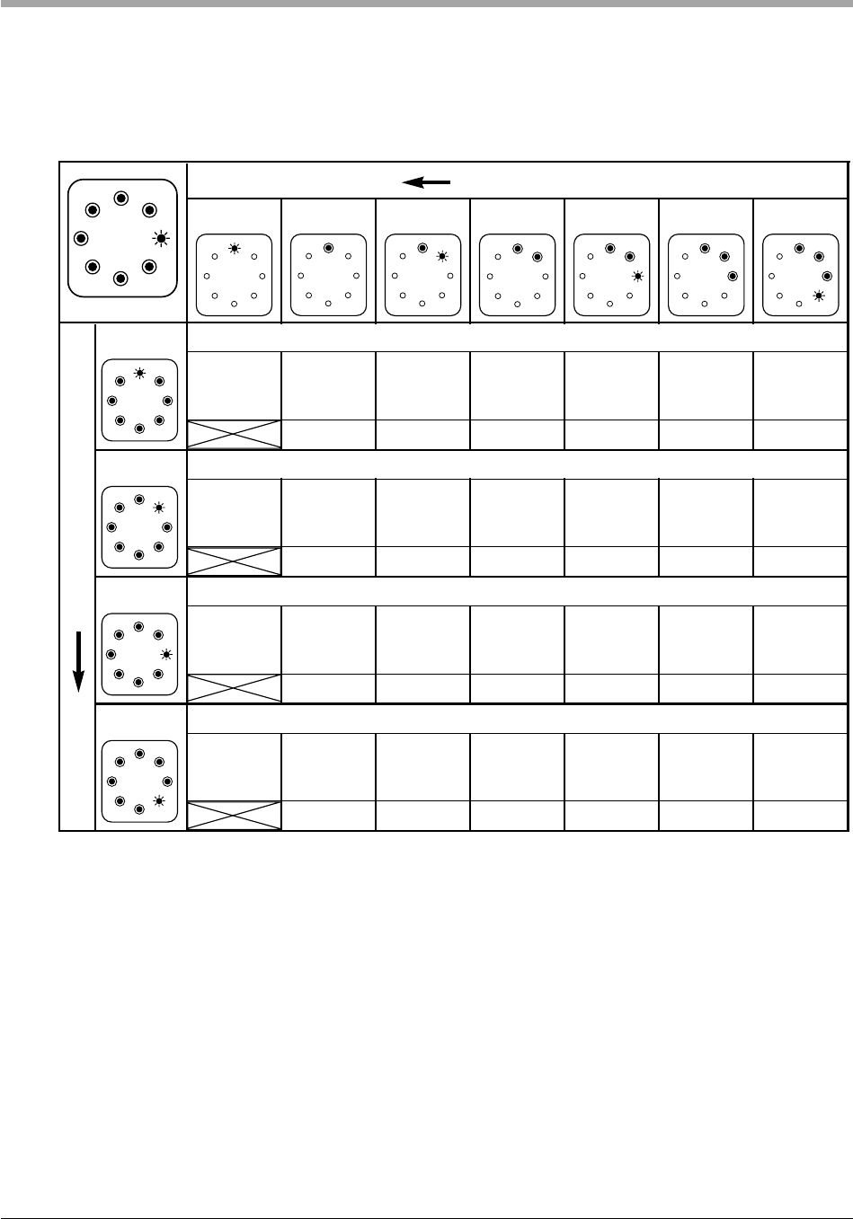
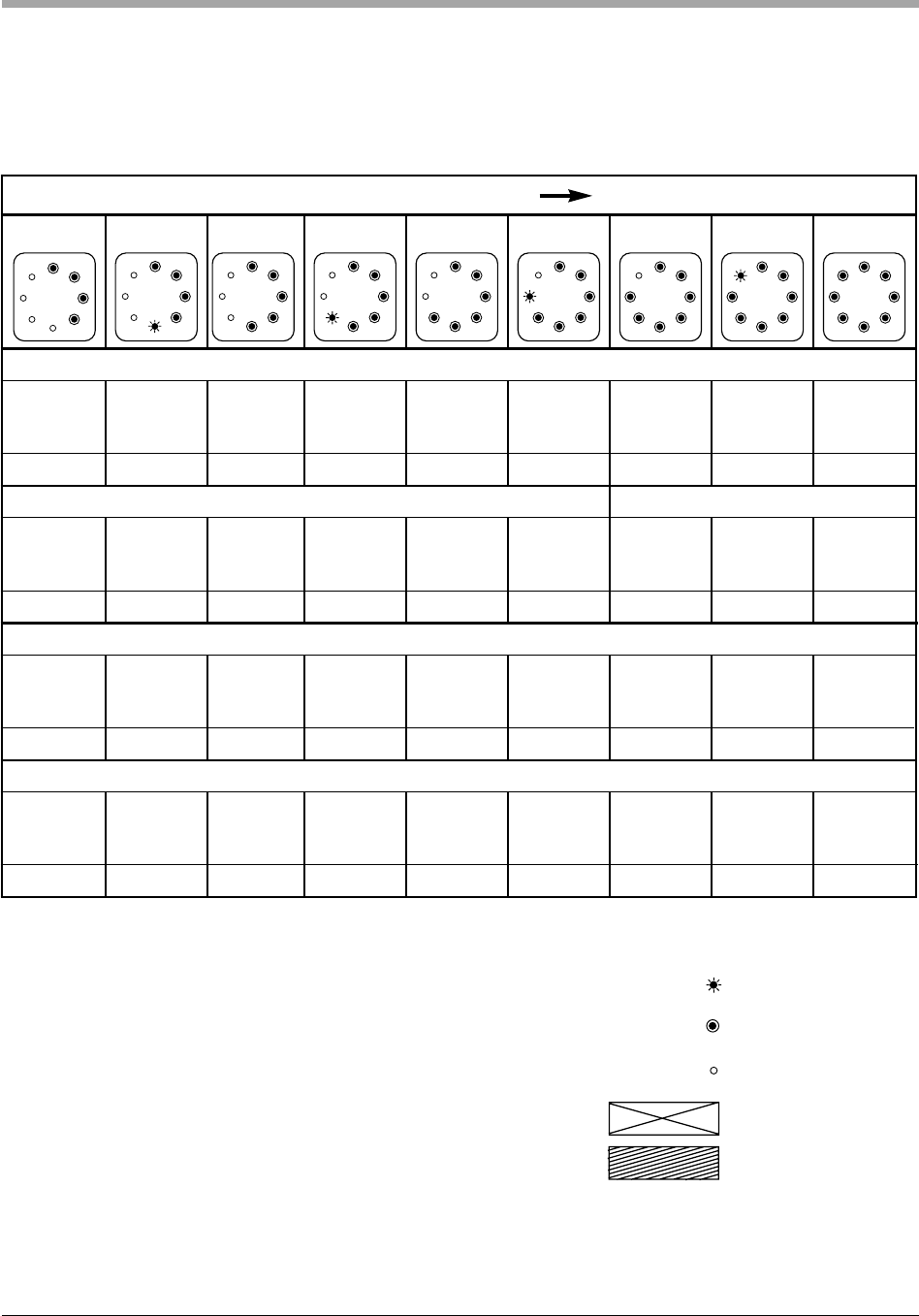
Programming of extended operator functions
Press button j (10) longer than 10 sec. The control unit changes from operating
mode to programming level for extended operator functions, LED 8 flashes quickly,
all other LED's are glowing. Hold button j pressed and select by means of
button h (11) or button g (12) the desired programming level (LED of level
flashes quickly, all other LED's are glowing). Now button j may be released. The
first programming menu of the desired level is selected (LED1 flashes, all other
LED's are glowing). Changes of settings in programming menu are made by
actuating button h or g and can be saved by pressing button j. (If button j is
actuated without change of settings by means of buttons h or g,