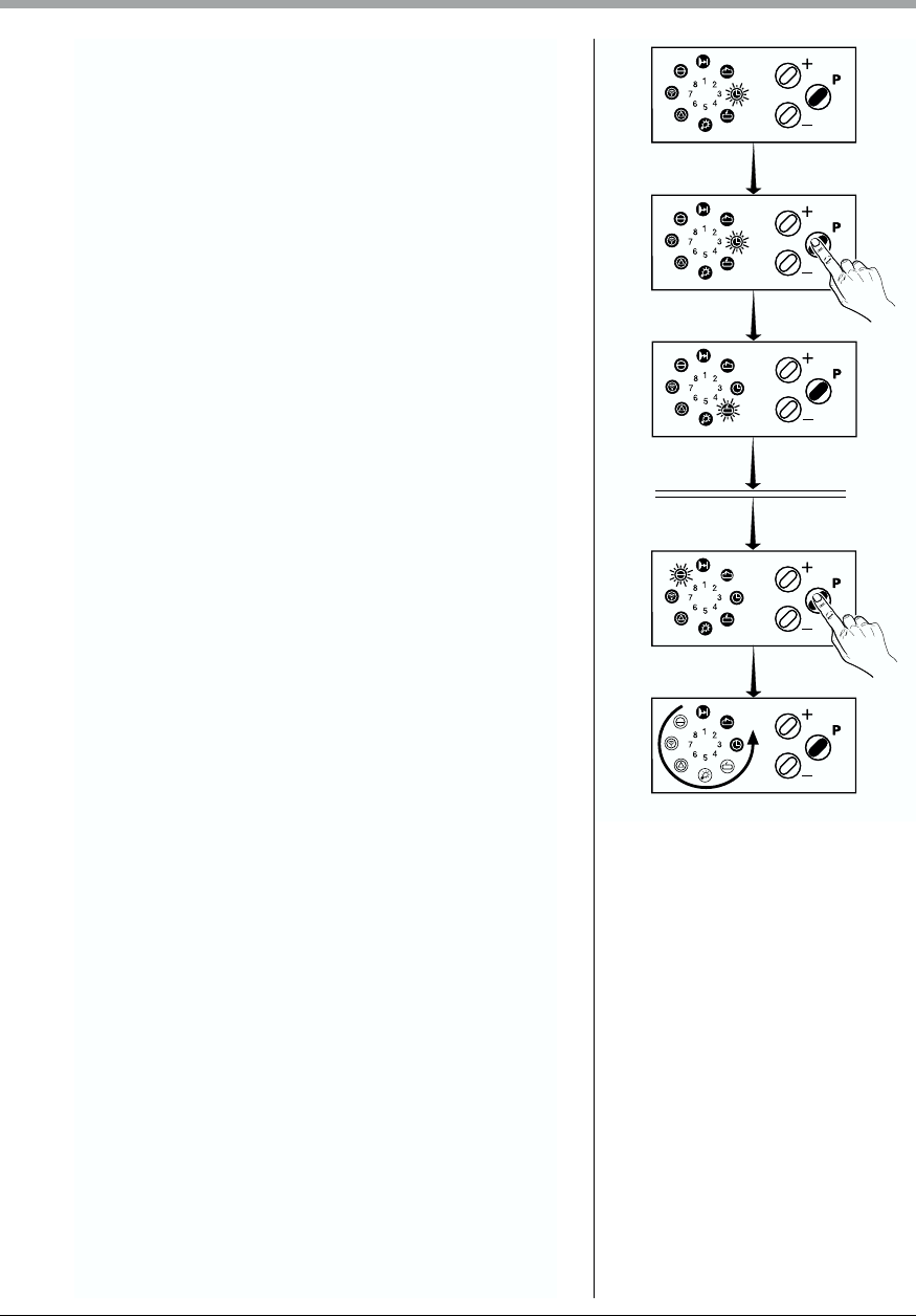
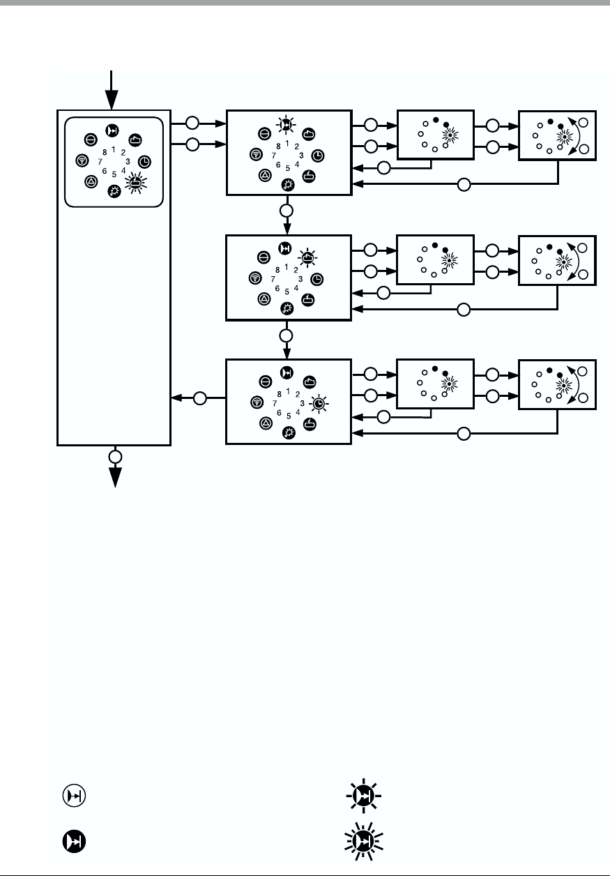
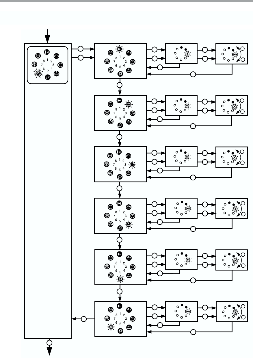
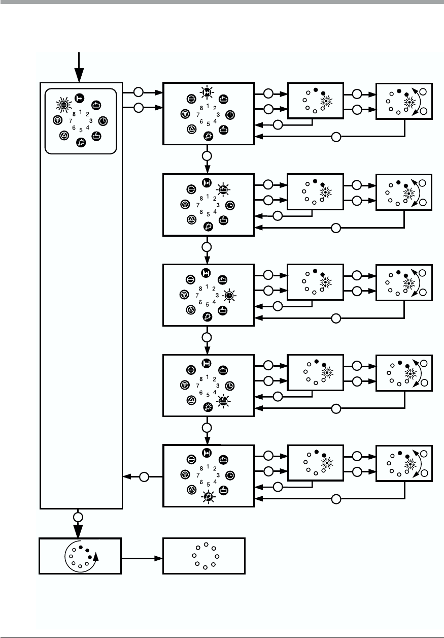
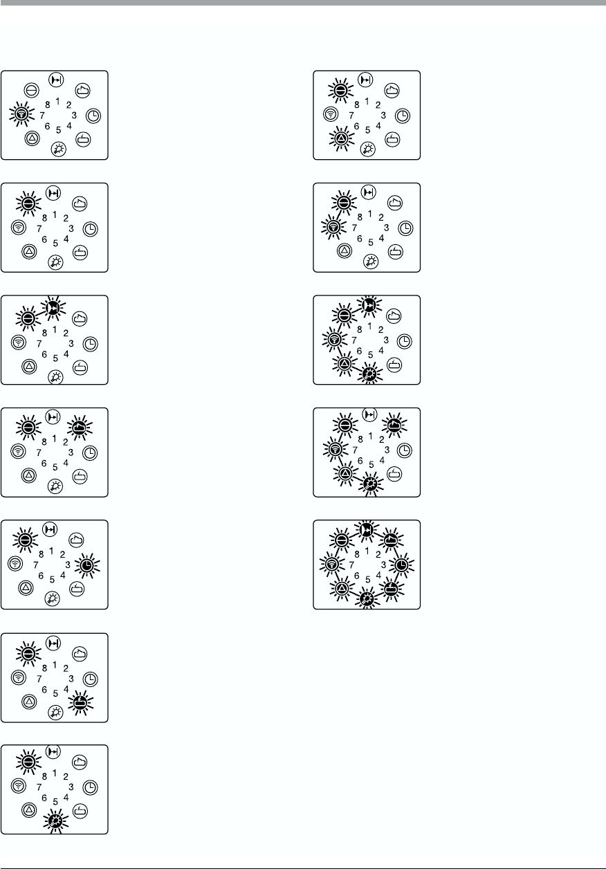
6. Display Functions and Programming Possibilities
English / Page 41
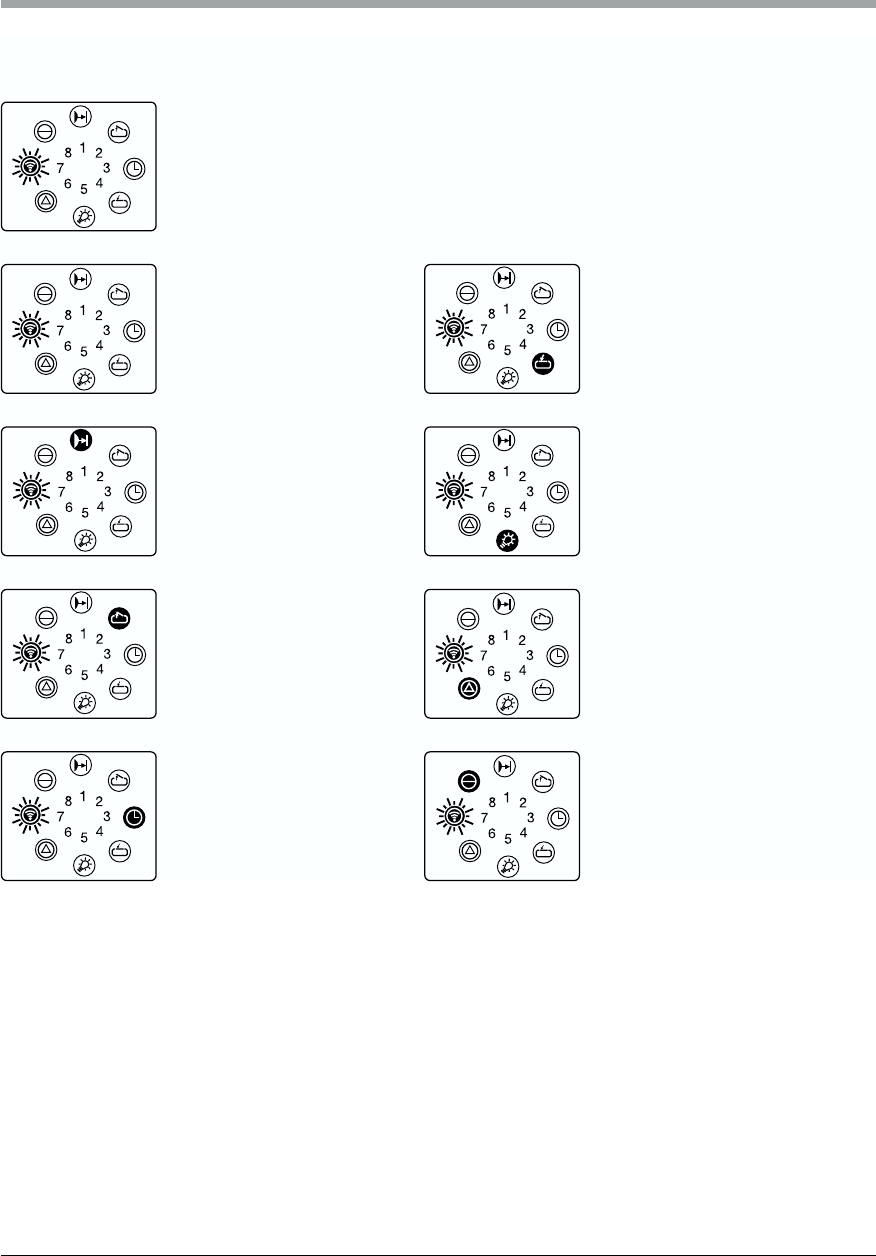
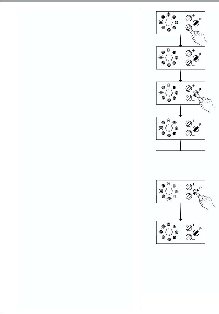
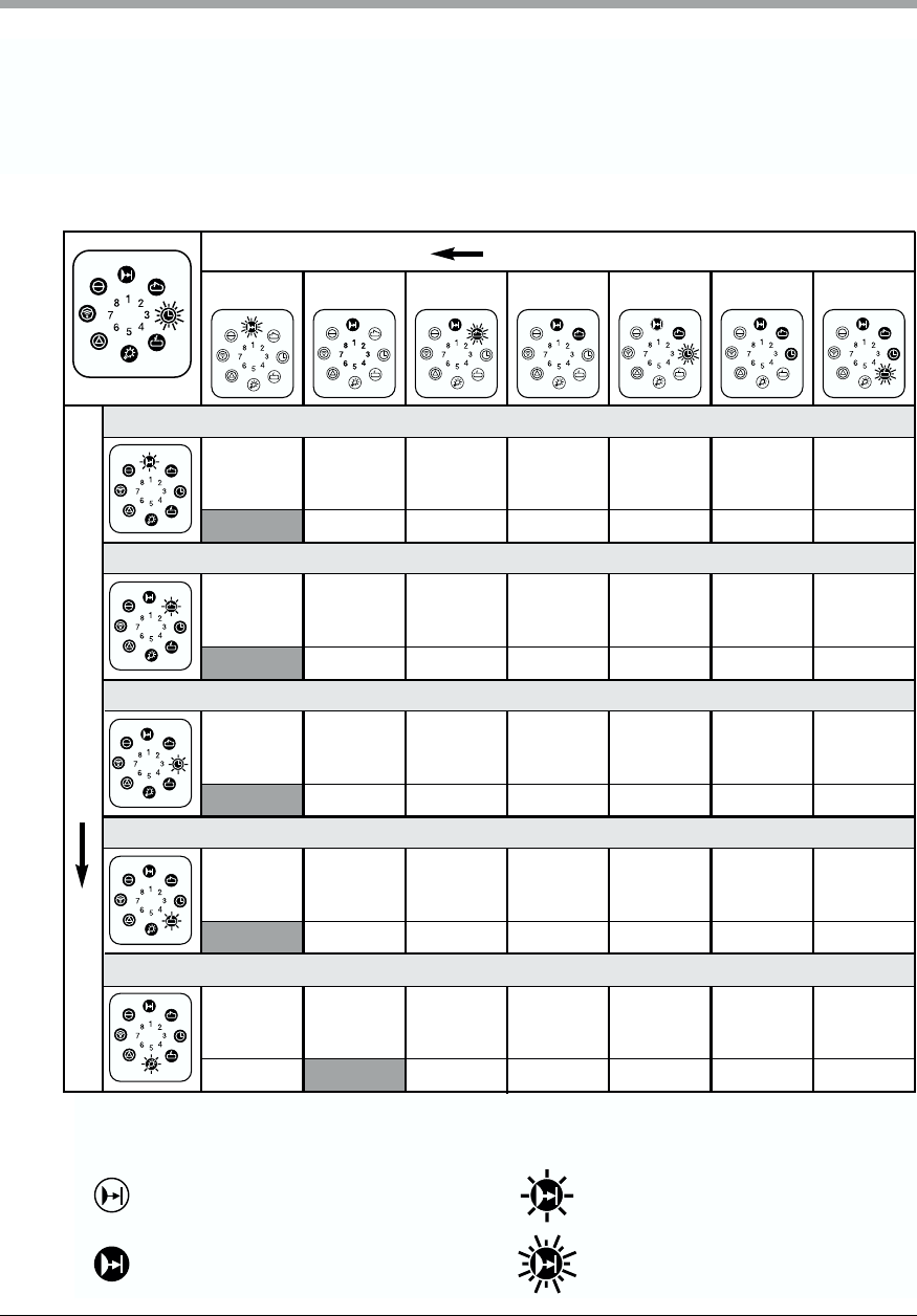
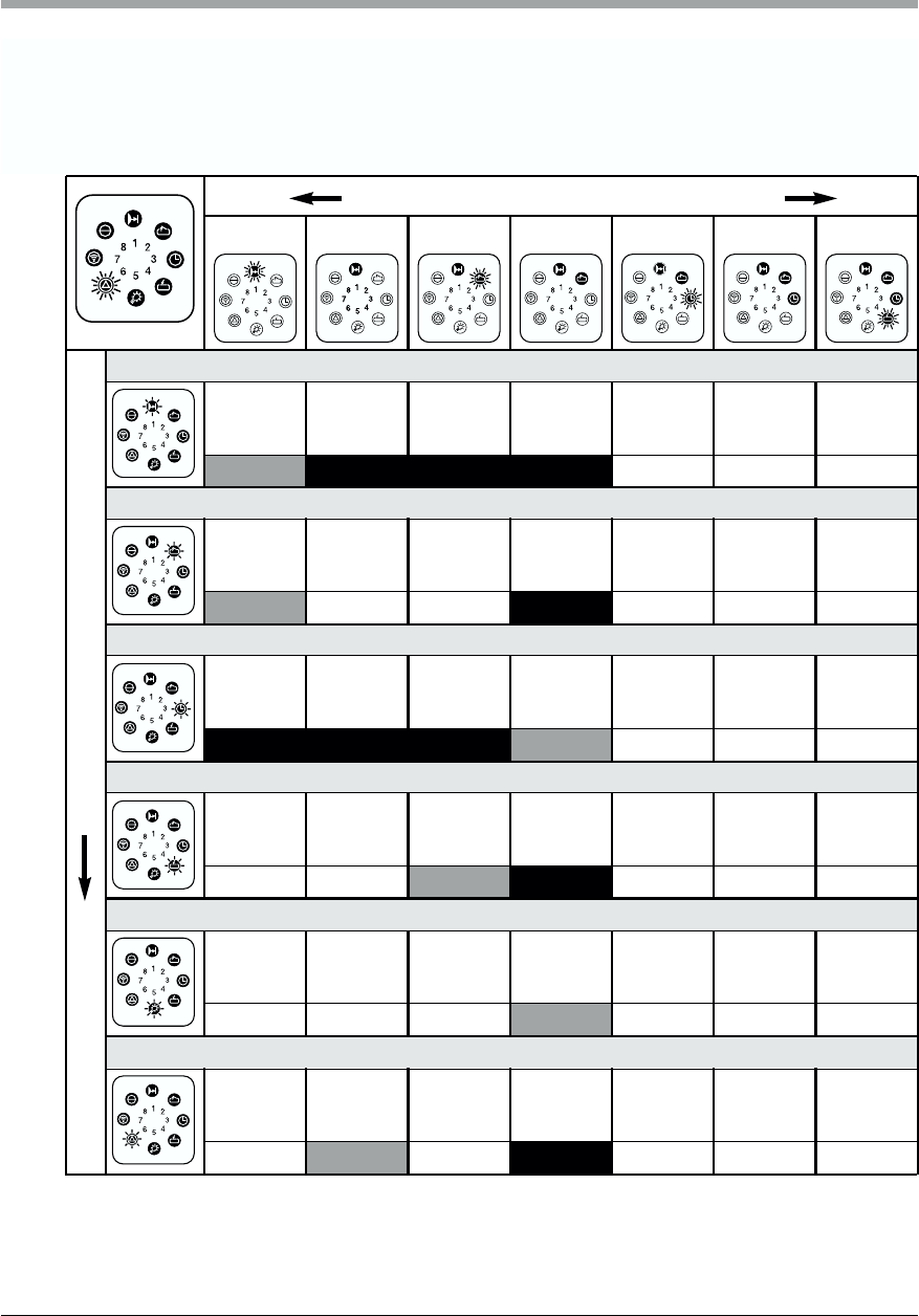
Explanation
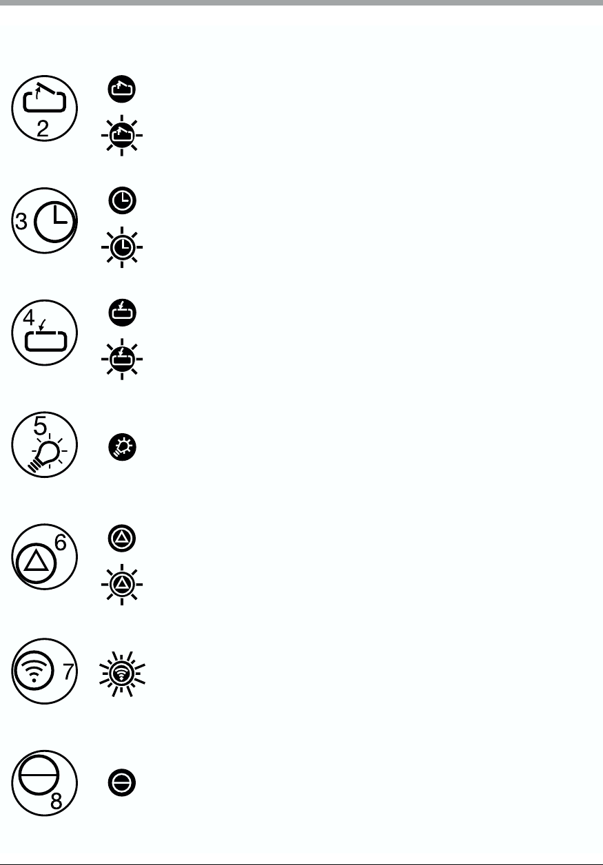
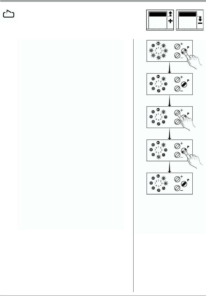
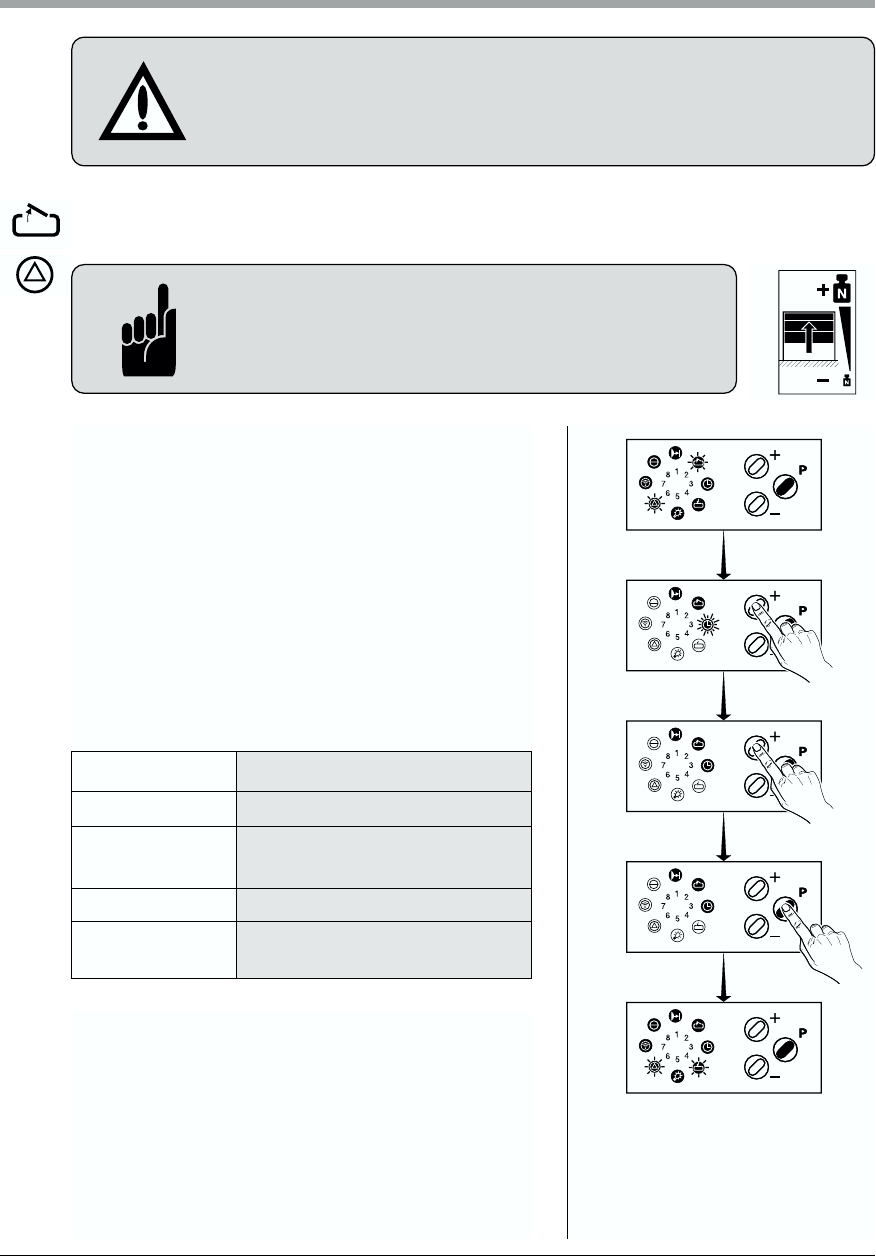
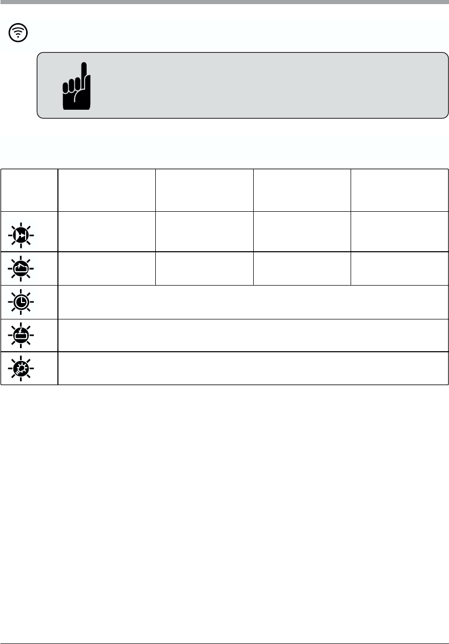
Time, in which the door is open, before door closes automatically.
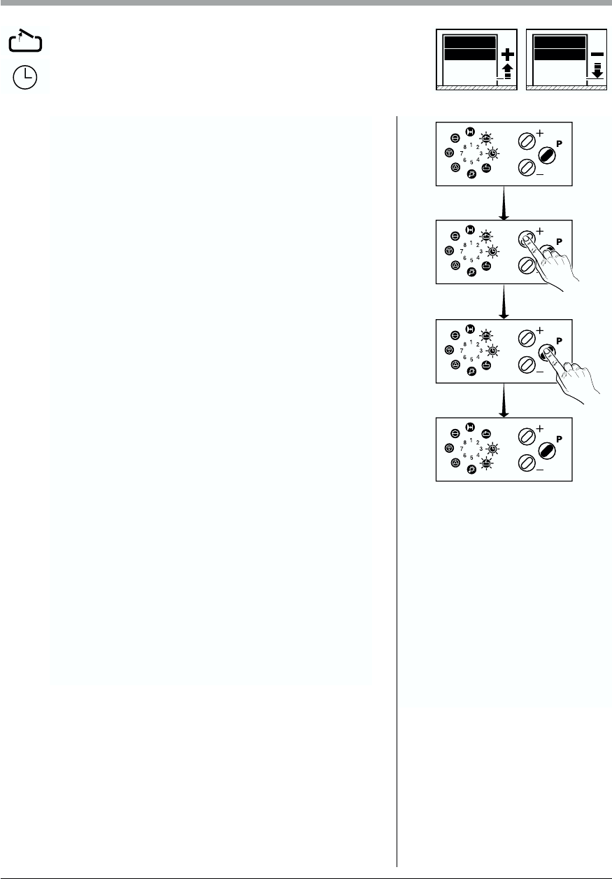
Time period, in which signal light flashes, before door closes
automatically.
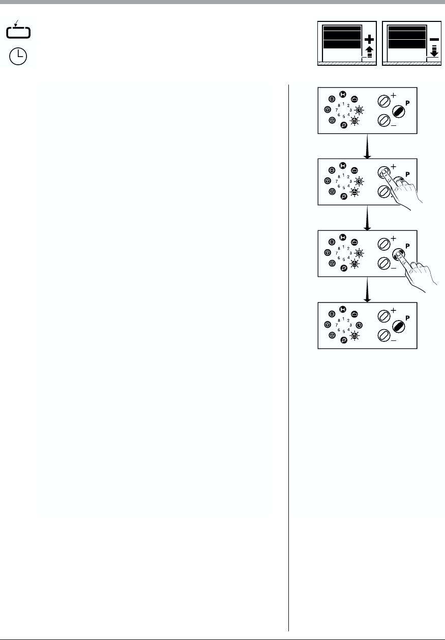
Time period, in which signal light flashes, before door starts to move
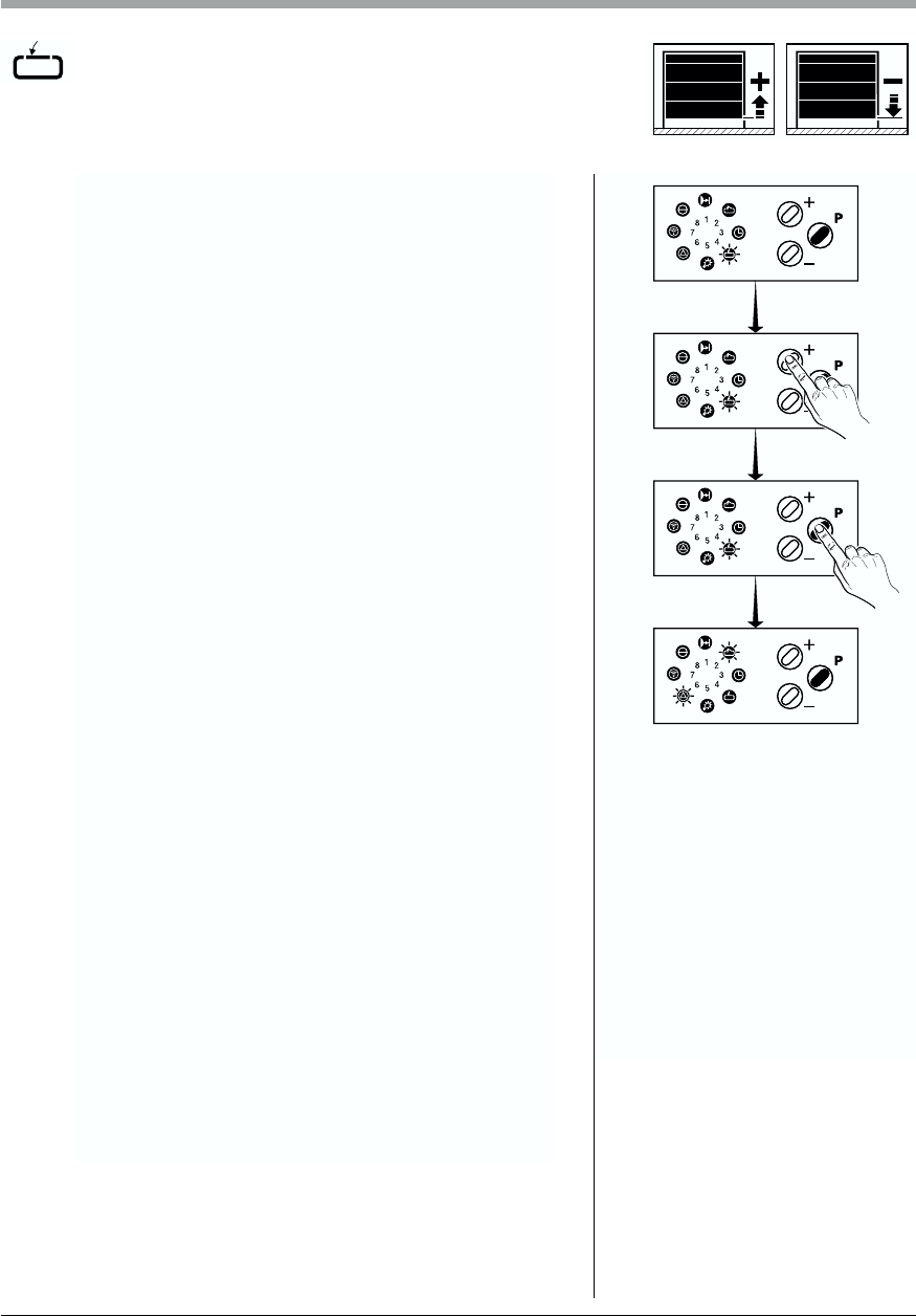
The door closes either after set open time or early after passing
photocell
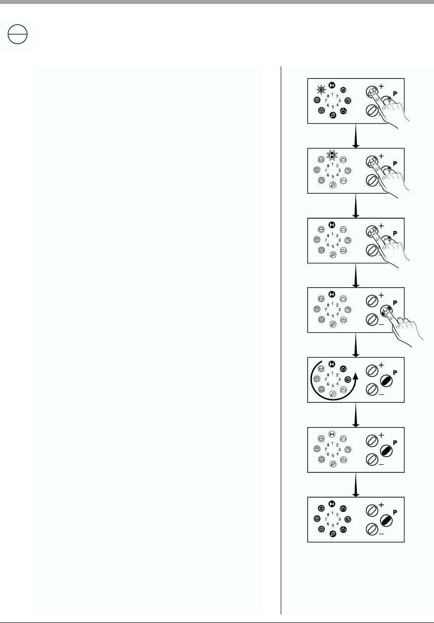
You have the choice between flashlight or permanent light for the
operation mode of the signal lights.
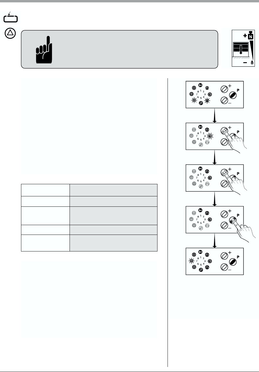
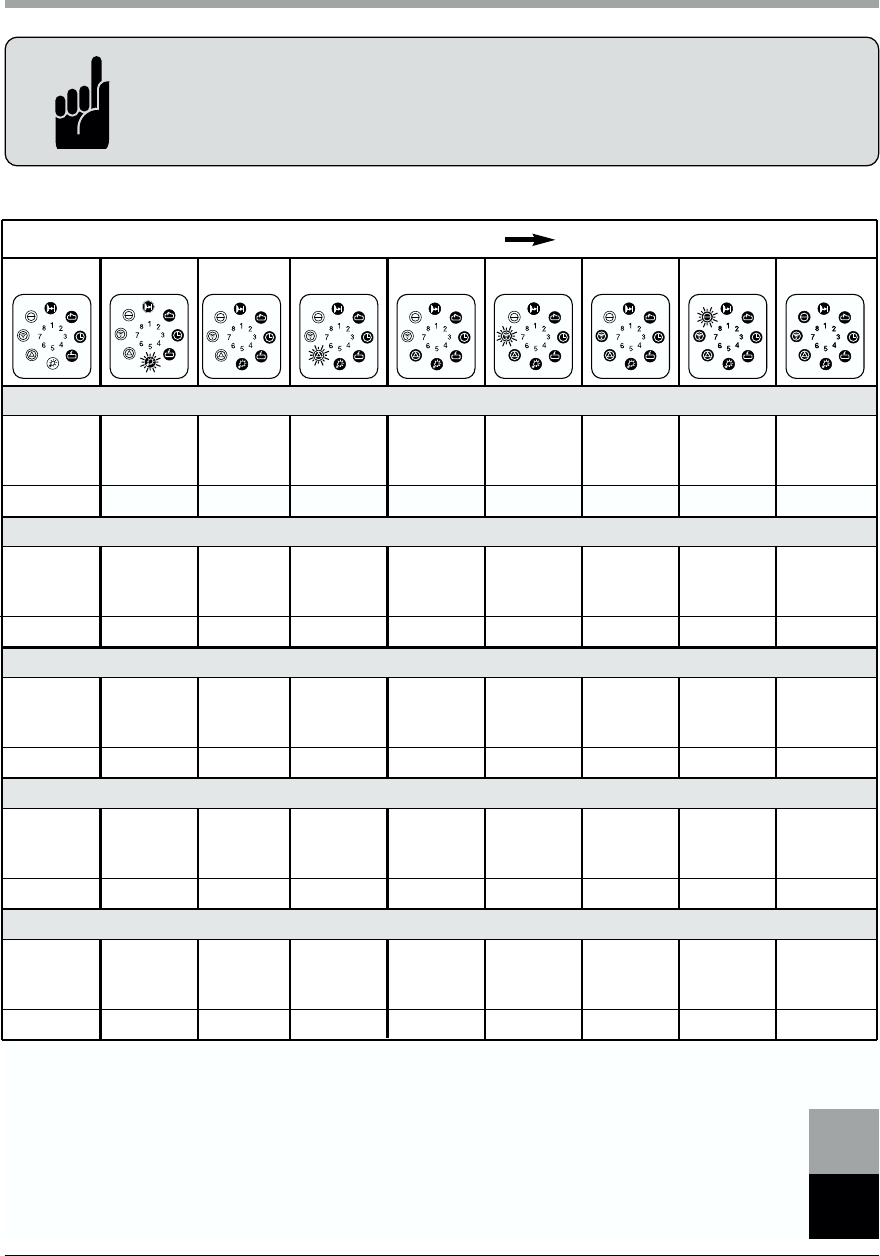
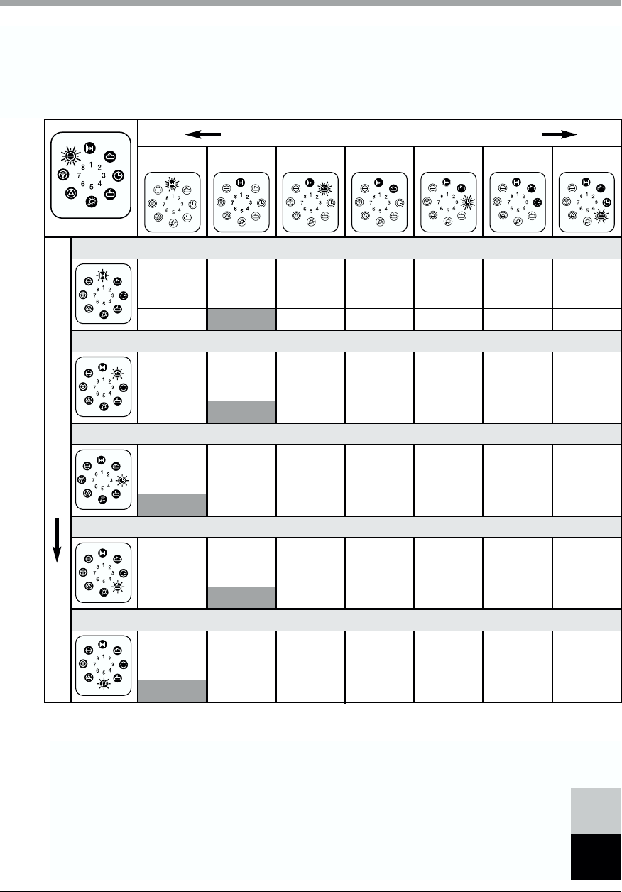
Time period in which the operater switches off without having reached
one of the end positions.
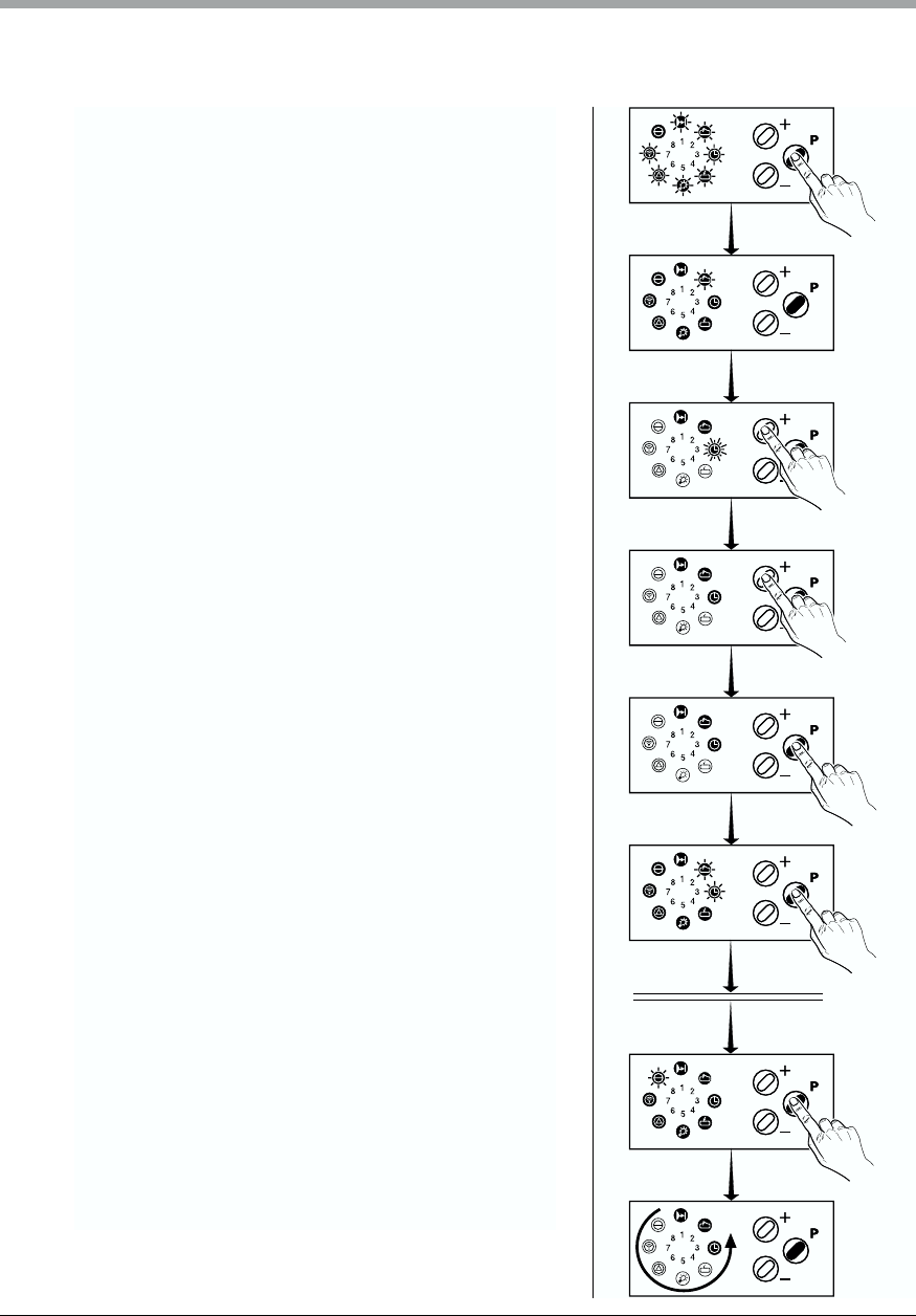
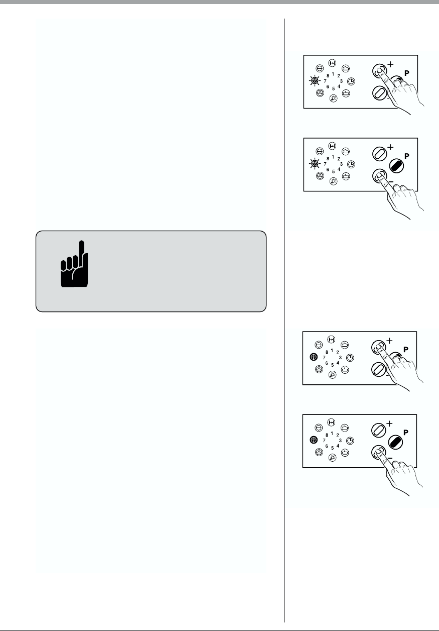
The learned power limit can be set in steps from 1 - 16
The sensibility of power limit can be set in steps from 1 - 16
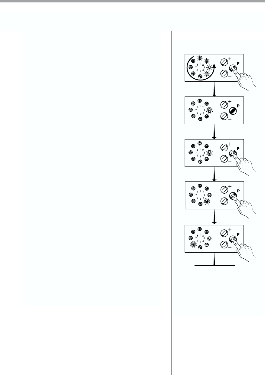
Possible settings: Operator STOP, short or long reversion
Possible settings: Operator STOP, short or long reversion
Possible settings: Operator STOP, short or long reversion
Possible settings: Operator STOP, short or long reversion
Possible settings: Operator STOP, short or long reversion
Possible settings: Operator STOP, short or long reversion
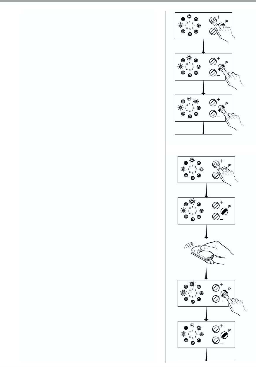
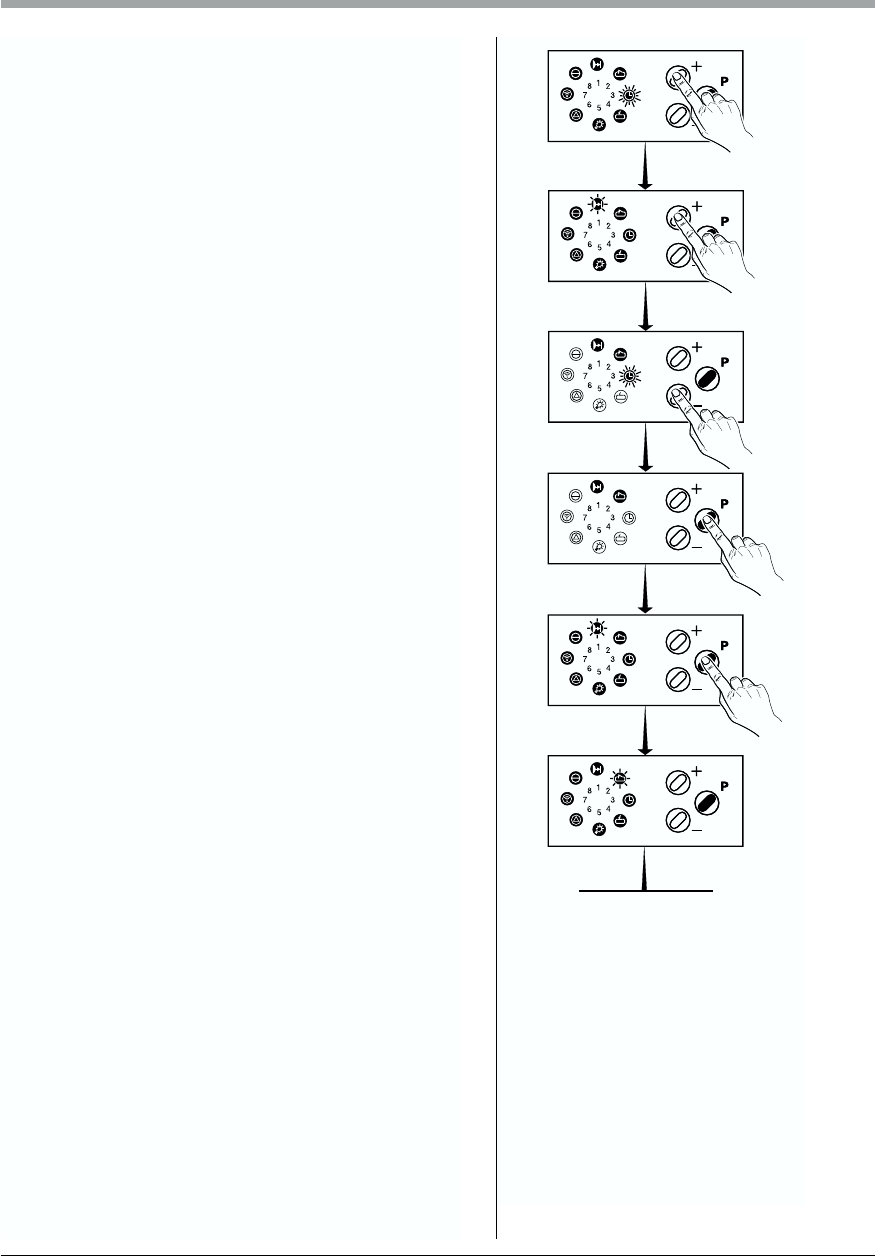
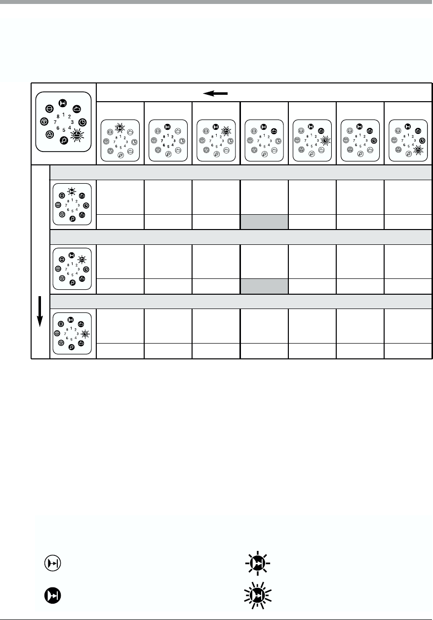
After start the operator travels to the pre-selected position
After start the operator travels to the pre-selected position
Actuation of the IMPULSE button when operator is running
Actuation of the direction button when operator is running
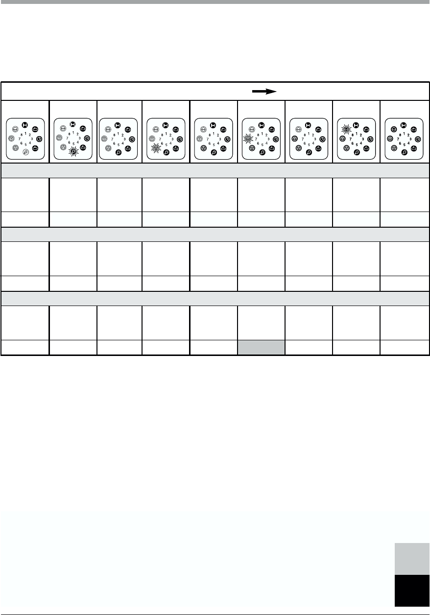
Intermediate positions, central control, master button, traffic control
Settings from factory
Automatic timer function
not activated
Automatic timer function
not activated
0 sec.
No
Flashlight
55 sec.
Step 4
Step 13
STOP
STOP
Not existing
Long reversion
Not existing
Short reversion
ON
ON
OFF
ON
Intermediate position