742810
35
Verklein
Vergroot
Pagina terug
1/36
Pagina verder
Control 120 - 123
Instructions for Initial Operation
and Wiring Scheme Manual
2
Explanation of the symbols
WARNiNG There follows important safety advice which must be
heeded in order to prevent bodily injury or material
damage!!
Installation instructions Instructions follow regarding mechanical or electrical
connection.
Programming instructions After connecting most of the control elements,
the control unit must first be programmed.
Operation check After connecting and programming most of the control
elements, it is advisable to test the function of the
control unit. Any fault can then be detected immediately
and time is saved in trouble-shooting.
Wiring schemes and circuit diagrams
ON, mains voltage
Impulse
Malfunction
OPEN
CLOSE
HALF OPEN
STOP
External control elements
Electronic aerial
External photocell
Transmitter (optosensor, photocell)
Receiver (optosensor, photocell)
Closing edge safety device
RPM sensor
Symbol Explanation
Symbols used in these instructions:
Symbols of control unit, operator etc:
1
2
N
N
OPEN power limit
CLOSE power limit
Open phase
Warning phase
Maintenance
To control unit
Cable slack switch
Connection lead
Wicket door switch
Symbol Explanation
3
1. Contents
Chapter Page
Figures inside of back cover
Explanation of the symbols
2
1. Contents 3
2. Important! Read carefully before carrying out any work 4
3. Initial operation of the Contol 120 - 123 control units
3.1 Control unit - operator connection 5
3.1.1 Dynamic 121 - 128 / Dynamic 300 6
3.1.2 Dynamic 3-101 - 3-108 6
3.2 Control unit - door leaf connection 7
3.3 Setting the reference point 9
3.3.1 Dynamic 121 - 128 / Dynamic 300 9
3.3.2 Dynamic 3-101 - 3-108 10
3.4 Setting the power limit and travel limits 13
4. Connecting the closing edge safety devices
4.1 Closing edge safety device (CLOSE - bottom of door) 13
4.2 Closing edge safety device (OPEN - top of door) 15
5. Connection and initial operation of the extensions
5.1 Automatic timer 16
5.2 Remote control 17
5.3 External control elements (description of function) 18
5.3.1 with system plug 18
5.3.2 without system plug 20
5.4 External photocell 21
5.5 Travel limit signals (relay) 22
5.6 Signal lights 23
5.7 Traffic light control 24
6. Appendix
6.1 Wiring diagrams 26
6.1.1 Control 120/121 wiring diagram 26
6.1.2 Control 122/123 wiring diagram 28
6.2 Test instructions 30
6.3 Function and error messages in the display 31
4
2. Important! Read carefully before carrying out any work!
This control unit may only be connected and put into operation by qualified and
suitably trained specialist personnel. For the purpose of this description qualified and
suitably trained specialist personnel are persons who are adequately instructed or
supervised by qualified electricians and are thus in a position to recognize the hazards
that electricity can cause. Moreover, they must hold qualifications consistent with the
work being carried out, in particular they must be
• knowledge of applicable electro-technological regulations,
• have received training in the use and maintenance of adequate safety equipment,
• as well as first aid training.
Before carrying out any cabling work, it is essential to disconnect the
control unit from the mains supply.
Observe local safety regulations!
Always lay mains cable and control cable separately!
Control voltage 24 V DC.
Before putting the control unit into operation, it is essential to ensure
that there are no persons or objects within the door's area of operation,
since a number of settings set the door in motion.
All available emergency command devices must be tested prior to initial
operation.
The door operator may only be installed with the door closed!
After installation and initial operation, those persons or their
representatives responsible for operating the door system must be shown how
the door system works!
No cables may be fed into the top of the control unit.
For technical reasons, the first time the control unit is switched on, the
door opens fully.
To carry out programming, the S11 programming switch on the main circuit
board must be set at the ON position. After initial operation it is
essential that this switch be returned to the OFF position in order to
prevent unintentional reprogramming of the control unit.
Special note for installation according to protection category IP 65:
At the very latest following initial operation, the plug connection to the
mains must be replaced by a direct mains connection with a mains isolator
switch!
Non-compliance with these warning and safety instructions can
lead to bodily injury and material damage.
5
3. Initial operation of the Control 120 - 123 control units
3.1 Control unit - door operator connection
Connect control unit according to picture B.
51 50 52
Fig. B/1: Connections in the control unit: C 120
Fig. B/2: Connections in the control unit: C 123
Connections in the control unit:
50. Protective conductor terminal
51. Mains lead to operator
52. RPM sensor socket
Legend for wiring diagrams:
Connecting terminals:
X3 Operator
X3a Motor
Plug connections:
X40 Operator RPM sensor
X41 Motor RPM sensor
51 50 52
6
3.1.1 Dynamic 121 - 128 / Dynamic 300
• Connect door operator according to picture C/1.
Connections in door operator:
53. protective conductor clamp
54. cable to mains
55. rpm sensor bush
3.1.2 Dynamic 3-101 - 3-108
• Connect door operator according to picture C/2.
Connections in door operator:
53. protective conductor clamp
54. cable to mains
55. rpm sensor bush
55 54 53
Fig. C/1: Connections in door operator
3. Initial operation of the Control 120 - 123 control units
Fig. C/2: Connections in door operator
These control units feature a static current circuit. If a malfunction
occurs in any of the safety devices, the static current circuit immobilizes
power operation of the door.
Elements within this static current circuit are the cable slack switch, the
wicket door switch andthe limit switches of the night lock.
O
55
O
53
O
54
7
3.2 Control unit - door leaf connection
Connecting the cable slack device (Dynamic 121-128 only)
Connect the system cable to this socket.
Note: To carry out the following operational check, it is important to ensure that
the optosensor (transmitter and receiver) is disconnected.
3. Initial operation of the Control 120 - 123 control units
* If connected, the short-circuit bridge must be removed.
If installed
Legend:
Switches (system plugs):
S5 Wicket door switch
S6 Cable slack switch
Switches (screw terminals):
S5a * Wicket door switch
S6a * Cable slack switch
S6b * Cable safety device
Plug connections:
X30 Closing edge safety device
(in the control unit)
X7a Coiled cable
X7d Cable slack switch
X7e Optosensor receiver
X7f Connection lead
X7g Wicket door contact
Connecting terminals:
X2c Static current circuit
(in the control unit)
X7b Coiled cable
X7c Coiled cable
X7h Static current circuit
X7l Cable slack switch
8
Insert the mains plug of the control unit into a site electric socket in
accordance with CEE standard 16 A.
Check that the voltage at the electric socket corresponds with that
given on the control unit's data plate.
For the Control 120/121 control units: the rotary field must be of
clockwise rotation!
Operation check of the mains connection and operator cabling
With the following settings, it is important to ensure that the door is
NEVER allowed to close or open fully. Halt the door at least 50 cm
before it reaches its mechanical travel limits by pressing the STOP
button (13).
• Half-open the door by hand.
• Switch on at the mains.
The VOLTAGE control light (1) should light up.
— If not, look up section 'no voltage' in the test instructions.
• Press the OPEN button (11).
The door should open.
— The door closes: press the STOP button, reverse the rotary field.
— The door doesn't move: look up section 'no response on
impulse' in the test instructions.
Operation check of the safety circuit
• Actuate each safety device separately.
Power operation of the door should now no longer be
possible.
— If this is not the case, check the electrical connection of the
respective safety device.
• Switch off at the mains.
3. Initial operation of the Control 120 - 123 control units
9
3.3 Setting the reference point
3.3 1 Dynamic 121 - 128 and Dynamic 300
Dynamic 121-128: Close the door manually.
Dynamic 300: Install boom in CLOSED position.Remove the operator's
transparent cover.Release the switching spindle by shifting the red no-load
lever (19) forward and pressing the wheel's inner carrier plate (20) towards the
spindle (see fig. D/1). Turn the knurled wheel (21) clockwise until the switching
carriage (22) is located approx. 5 mm in front of the left, bevelled collar of the
switching spindle (see fig. D/1).
Relatch the carrier plate and make secure by re-engaging the no-load lever
(makes an audible click on engaging), as shown in fig. D/2.
The door must now be opened fully by hand.
By means of the smaller knurled wheel (23), now turn the adjusting spindle,
until the switching carriage (22) actuates the reference point switch (24)
(see fig. D/2). Now rotate the smaller knurled wheel (23) approx. 1 - 2 turns
anti-clockwise.
3. Initial operation of the Control 120 - 123 control units
19
20
21
22
ca. 5 mm
Fig. D/1: Setting the reference point (door is closed)
10
Return the transparent cover to the operator.
3.3 2 Dynamic 3-101 - 3-108
1. Move the door by hand to its mechanical travel limit OPEN.
2. Open housing cover on door operator.
3. Release the stop (grub screw J) of control cam (B).
4. Set control cam (B) in such way, that the reference point switch (G)
is actuated according to fig. 7 (position H) - approx. 2 angular degrees from
switch point.
5. Fix control cam (B) by screwing on grub screw (J).
6. Then install housing cover again.
7. Connect to power supply and actuate buttom CLOSE (12).The door travels
to its travel limit CLOSE which is set by factory.
3. Initial operation of the Control 120 - 123 control units
23
24
22
Fig. D/2: Setting the reference point (door is open)
Fig. D/3: Setting the reference point
B
G
H
J
ABCDEF
11
3.4 Setting the power limit and travel limits
Note: For the following settings, the S11 programming switch on the main circuit
board must be set at the ON position. After completing programming it is
absolutely essential that this switch be returned to the OFF position in order
to prevent unintentional reprogramming of the control unit!
Switch on at the mains. All the control unit's light elements light up for
approx. 2 seconds.
Setting the power limit
Set the power limit to be as sensitive as possible!
Dynamic300: Only the stages 7 - 15 are effective.
OPEN power limit (setting the maximum pull force):
• Press button P(15)
OPEN travel limit control light (2) flashes.
• Press button M(16) until... OPEN POWER LIMIT control light (6)
flashes.
• Press the buttons OPEN (11) or Set pull force is altered and displayed
CLOSE (12) briefly in increments from 0 - 15.
• Press button P Set pull force is stored; programming is
completed.
CLOSE power limit (setting the maximum push force):
• Press button P
OPEN travel limit control light flashes.
• Press button M(16) until... CLOSE POWER LIMIT control light (7)
flashes.
• Press the buttons OPEN or Set push force is altered and displayed
CLOSE briefly in increments from 0 - 15.
• Press button P Set push force is stored; programming
is completed.
Operation check:
• Even if the power limit has been set to be relatively sensitive, the door
can still be opened and closed without interruption.
Stetting the travel limits
Setting the OPEN travel limit:
Rough adjustment:
• Press button P The OPEN travel limit control light flashes.
• In dead man’s mode, operate the door
to reach the desired travel position
• Press button P The control light glows permanently.
3. Initial operation of the Control 120 - 123 control units
12
Fine adjustment:
• Press button P The OPEN travel limit control light flashes.
• Press the OPEN and CLOSE buttons The travel limit is altered by approx. 3 mm
briefly and is indicated in the display.
• Press button P Programming is completed.
Setting the CLOSE travel limit:
Rough adjustment:
• Press button P The OPEN travel limit control light flashes.
• Press button M until ... the CLOSE travel limit control light flashes.
• In dead man’s mode, operate the door
to reach the desired travel position
• Press button P The control light glows permanently.
Fine adjustment:
• Press button P The OPEN travel limit control light flashes.
• Press button M until ... the CLOSE travel limit control light flashes.
• Press the OPEN and CLOSE buttons The travel limit is altered by approx. 3 mm
briefly and is indicated in the display.
• Press button P Programming is completed.
Note: The HALF OPEN intermediate travel limit cannot be set until the OPEN and
CLOSE travel limits have been set.
Setting the HALF OPEN intermediate travel limit:
• Press button P The OPEN travel limit control light flashes.
• Press button M until ... the HALF OPEN travel limit control light
flashes.
• In dead man’s mode, operate the door
to reach the desired travel position
• Press button P The control light glows permanently.
Operation check:
• Operate the door to arrive at its end of travel positions. As soon as the
set travel limits have been reached, the corresponding control lights light
up in the control unit. If necessary, repeat the fine adjustment procedure
to achieve the optimum setting.
• The reference point switch has to be actuated above the passage height.
When passing the reference point the control light IMPULSE shortly lights
up.
*Dead man's mode: The door is moved by pressing and holding the OPEN or CLOSE buttons.
3. Initial operation of the Control 120 - 123 control units
13
4.1 Closing edge safety device (CLOSE - bottom of door)
Function: This closing edge safety device monitors the bottom door seal. If whilst
closing the door meets with an obstruction, the closing edge safety
device automatically halts the door and lifts it to clear the obstruction.
Connecting the closing edge safety device
Insert the optosensor bungs into the bottom door seal and connect them to the
electricity supply.
4. Connecting the closing edge safety devices
* If connected, the short-circuit bridge must be removed.
+ Dynamic 121-128 only
Legend:
Programming switches:
S2b Press-and-release
operation mode
Switches (system plugs):
S5 Wicket door switch
S6 + Cable slack switch
Switches (screw terminals):
S5a * Wicket door switch
S6a * + Cable slack switch
S6b * Cable safety device
Plug connections:
X30 Closing edge safety device
X7a Coiled cable
X7d + Cable slack switch
X7e Optosensor receiver
X7f Connection lead
X7g Wicket door contact
Connecting terminals:
X2c Static current circuit (in
the control unit)
X7b Coiled cable
X7c Coiled cable
X7h Static current circuit
X7l Cable slack switch
Optosensors:
V5 Transmitter
V6 Receiver
14
The sensitivity of the closing edge safety device can be adjusted via the duplex
switch on the optosensor circuit board.
Aim for maximum sensitivity!
In the case of wider doors, where the light in the bottom door seal is
substantially reduced, the sensitivity setting must be reduced accordingly.
Displays on the optosensor circuit board:
GREEN LED: Voltage
YELLOW LED: Static current circuit closed (should go out when
cable slack or wicket door device actuated)
RED LED: Optosensor function indicator (should go out when
light beam interrupted)
Operation check of the closing edge safety device:
• Switch on at the mains.
• Operate the door to arrive at its OPEN travel limit.
• Press the CLOSE button (12).
The door should close by press-and-release.
— If not, check the optosensor (see test instructions)
• Whilst the door is still closing, press the bottom door seal together.
The door should come to a halt, then rise a short distance.
— If not, check the optosensor (see test instructions)
• Switch off at the mains.
Test instructions for optosensors
The function of the optosensors should be checked at least once a year in
order to guarantee safe operation of the door system.
To carry out the check, proceed as follows:
Interrupt the light path in the bottom door seal; this can be achieved by
deforming the seal or by removing the transmitter or receiver bung. It should
now not be possible to subsequently close the door by press-and-release
operation.
Clear the light path in the bottom door seal again; now it should be
possible to close the door again by press-and-release operation.
4. Connecting the closing edge safety device
ON
OFF
ON
OFF
ON
OFF
ON
OFF
Max.
Min.
15
4.2 Closing edge safety device (OPEN - top of door),
if installed
Function: This closing edge safety device monitors the top door seal. If whilst
opening the door meets with an obstruction, the closing edge safety
device automatically halts the door and reverses its direction to clear the
obstruction.
Connecting the closing edge safety device
Connect the lead to the X32 socket. Insert the optosensor bungs into the top
door seal and connect them to the electricity supply.
For further details please refer to the Installation Instructions supplied with the
closing edge safety device.
4. Connecting the closing edge safety devices
16
5.1 Automatic timer
The automatic timer function is not available until a closing edge safety
device has been fitted to the bottom of the door leaf.
It is only permissible to use this function in conjunction with signal lights!
Function: This function allows an open door to close again automatically
after a preprogrammed time (OPEN PHASE) has elapsed. In order
to ensure that the closing door does not pose a hazard, the signal
lights flash for a pre-set WARNING PHASE as soon as the OPEN
PHASE has elapsed (for connection see page 23).
(OPEN PHASE + WARNING PHASE = time during which the door actually remains open).
The automatic timer is not programmed ex works, i.e. it is switched off.
Programming the automatic timer
Warning phase:
• Press button P(15) The OPEN travel limit control light flashes.
• Press button M(15) until... the WARNING PHASE control light flashes.
• Press OPEN (11) or CLOSE (12) buttons The warning phase is set in increments
briefly of 2 sec.
Maximum: 32 sec., minimum: 2 sec.
The set time phase appears in the display
• Press button P The time for the warning phase is stored.
Open phase:
• Press button P(15) The OPEN travel limit control light flashes.
• Press button M(15) until... the OPEN PHASE control light flashes.
• Press OPEN or CLOSE buttons briefly The open phase is set in increments of
5 sec.
Maximum: 95 sec., minimum: 5 sec.
The set time phase appears in the display
• Press button P The time for the open phase is stored.
To switch off the automatic timer, programme 0 sec. for both phases (warning
and open phase).
Operation check:
• Operate the door to travel to its OPEN travel limit.
The door should close once the set time phase has elapsed.
5. Connection and initial operation of the extensions
17
5.2 Remote control
Set your own personal code via the code switches in the hand transmitter.
Connecting the electronic aerial
Connect the electronic aerial to socket X20a (26) in the control unit. Make sure
that the aerial cordon is completely rolled out and properly aligned to achieve the
best possible range. Install well away from metal parts as these have a screening
effect!
If you operate two photocells, connect the aerial in accordance with the
wiring diagram on page 21.
Adapting the control unit to a hand transmitter
The remote control unit can memorise 2 different remote control codes.
• Press button P (15) The OPEN TRAVEL LIMIT control light flashes.
• Press button M (16) until... The REMOTE CONTROL control light flashes.
• Press the OPEN (11) or CLOSE (12) The first or second code is set;
buttons briefly E or I appears in the display.
• Press button P Storage commences
• Operate the hand transmitter Coding is memorised; if within 10 sec. the
control unit recognizes a valid signal,
the storage procedure is completed.
Operation check:
• Operate the hand transmitter from a distance of approx. 15 m.
The door should now start to move
If not, look up the 'remote control' section in the test instructions.
5. Connection and initial operation of the extensions
18
5.3 External control elements
External control elements can actuate various functions:
STOP: The operator can no longer be actuated, a moving door is
brought to a halt.
IMPULSE: The door is opened (exception: if the door has already
reached its opening limit, it then closes). A moving door
cannot be halted.
OPEN: The door is opened. A moving door is brought to a halt.
If the automatic timer is switched on, the OPEN PHASE is
extended.
CLOSE: The door is closed. A moving door is brought to a halt.
If the automatic timer is switched on, the CLOSE PHASE is
reduced.
5.3.1 Connecting external control elements with system plugs
Examples for external control elements with system plugs:
• Push buttons of the Command Series
• Code keypad Command 201
• Key switch Command 311 and 411
Connecting the control elements
Note: If several key switches or code keypads are connected, the coupling for plug
systems (for series connection), item no. 151 228, is required. Instructions on
connecting several control elements are contained in the connection plan
supplied with the coupling.
Before connecting external control elements, the short-circuit plug must be
withdrawn from the X10 (27) socket in the control unit.
The control elements with system plug can now be connected to this socket.
5. Connection and initial operation of the extensions
19
Operation check:
• Operate the external control element
The desired function should be carried out.
5. Connection and initial operation of the extensions
20
5.3.2 Connecting external control elements without system plugs
Examples for external control elements without system plugs:
• Pull switch Command 701
• Push button Command 601 and 602
• Code keypad Command 202
Connecting the control elements
Connect the control elements to the terminal block X2c (39).
The following functions are available at the X2c terminal block:
S0 (STOP): Connection: Terminals 12 & 13 (remove short-circuit bridge!
Contact type: Opener
Connection method: Several contacts must be connected in
series!
S1 (IMPULSE):Connection: Terminals 20 & 21
Contact type: Closer
Connection method: Several contacts must be connected parallel!
S2 (OPEN): Connection: Terminals 14 & 15
Contact type: Closer
Connection method: Several contacts must be connected parallel!
S4 (CLOSE): Connection: Terminals 16 & 17
Contact type: Closer
Connection method: Several contacts must be connected parallel!
Operation check:
• Operate the external control element
The desired function should be carried out.
5. Connection and initial operation of the extensions
21
5.4 External photocells
Function: The external photocell monitors the door's through traffic area.
If the closing door encounters an obstruction in this area, it opens again
fully. If the automatic timer is switched on, actuation of the photocell
extends the OPEN phase.
Connecting one photocell Special 613, item no. 153 550
Special 614, item no. 152 675
Special 615, item no. 152 703
Open the cover plate in the control unit and set the programming switch S20 (36)
on the control circuit board to OFF. Connect the photocell to the socket X20 (28)
in the control unit. Cabling of the photocell is carried out as shown below.
Wiring diagram for photocell connection:
Connecting a further photocell
Open the cover plate in the control unit and set the other programming switch
S20a (36) on the control unit circuit board to OFF.
The second photocell is connected to the aerial socket X20a (26). If an aerial is
already connected to this socket, then an adapter (coupling for plug system,
3-pin, item no. 562 849) and a flat cable (item no. 562 759) must be connected in
accordance with the above wiring diagram.
5. Connection and initial operation of the extensions
22
5.5 Travel limit signals (relay)
Function: On reaching the OPEN/CLOSE travel limits, the corresponding relay
connects.
Connecting the relay output circuit board (item no. 153 044)
Note: You may find it necessary to add a small system housing with circuit board
carrier (item no. 153 220) to the control box.
Always attach the flat-cable plugs so that the cable is angled in the
direction of the circuit board edge.
Connect the relay circuit board and control unit using the enclosed flat cable.
Relay circuit board: Plug connection X4
Control unit: Plug connection X8a (33)
Wiring diagram detail of travel limit signals (relay)::
5. Connection and initial operation of the extensions
Legend:
D1 CLOSE control light
D2 OPEN control light
H1 CLOSE signal light
H2 OPEN signal light
K1 CLOSE relay
K2 OPEN relay
Plug connections:
X4 Relay triggering
X8a Travel limit relay (in the
control unit)
23
5.6 Connecting the signal lights for the automatic timer function
(Control 220, item no. 152 814)
Function: The signal lights flash when the operator is running.
If the automatic timer is switched on, the signal lights also flash during
the warning phase (for programming see page 16).
Connecting the relay circuit board
Always attach the flat-cable plugs so that the cable is angled in
the direction of the circuit board edge.
Connect the relay circuit board and the control unit using the enclosed
flat cable.
Relay circuit board: Plug connection X4a
Control unit: Plug connection X8b (32)
Wiring diagram detail for signal lights relay:
5. Connection and initial operation of the extensions
Legend:
D40 SIGNAL LIGHTS control light
F 5 Mains fuse (max. 4A)
H41 EXIT signal light (amber)
H43 ENTER signal light (amber)
K40 SIGNAL LIGHTS relay
Plug connections
X4a Relay triggering
X4b Relay triggering
X8b Signal lights relay (in the control unit)
24
5.7 Traffic light controls
Connecting the traffic light controls (Control 310, item no. 152 816)
Always attach the flat-cable plugs so that the cable is angled in the direction of
the circuit board edge.
Connect the relay circuit boards and the control unit using the enclosed flat
cables.
Relay circuit board 1 (item no. 153 112): Plug connection X4a
Control unit: Plug connection X8b (32)
Relay circuit board 2 (item no. 152 116): Plug connection X4
Control unit: Plug connection X8c (34)
Button connecting circuit board 1 (item no. 152 117): Plug connection X5f
Control unit: Plug connection X5E (31)
Wiring diagram detail for traffic light controls:
5. Connection and initial operation of the extensions
Legend:
D1 EXIT control light
D2 ENTER control light
D40 SIGNAL LIGHTS control light
F 5 Mains fuse (max. 4A)
H41 EXIT signal light (red)
H42 EXIT signal light (green)
H43 ENTER signal light (red)
H44 ENTER signal light (green)
K1 EXIT relay
K2 ENTER relay
K40 SIGNAL LIGHTS relay
Plug connections
X4 Relay triggering
X4a Relay triggering
X4b Relay triggering
X8b Signal lights relay (in the control unit)
X8c Traffic flow control relay (in the control
unit)
25
Continuation of wiring diagram detail for traffic light controls:
For programming the times to regulate the traffic flow see page 16.
5. Connection and initial operation of the extensions
Legend:
S30 EXIT impulse
S31 ENTER impulse
S32 Automatic ON/OFF
Plug connections:
X5a ENTER button connection
X5b EXIT button connection
X5c Photocell (optional)
X5d Automatic ON/OFF button connection
X5e Button extension
X5f Button connecting circuit board
X5E Button connecting circuit board
(in the control unit)
26
Observe local safety regulations! Always lay mains cable and control cable
separately! Control voltage 24 V DC. Attention low voltage! External voltage
at the terminals X2c, X5 to X41 will completely destroy the electronics!
6.1.1 Wiring diagram of the Control 120/121 control units
6. Appendix
27
Connection plans for accessories (detail):
Rel8a TRAVEL LIMITS relay
see page 22
Rel8b SIGNAL LIGHTS relay
see page 23
SKS1 Closing edge safety device
see page 13
SKS2 OPEN closing edge safety device
see page 15
V20 External photocell
see page 21
W20 Electronic aerial
XS10 External control elements
see page 18
Inp5a Button connecting circuit board
see page 25
Legend:
K1 OPEN inversion relay
K2 CLOSE inversion relay
M1 Motor with thermal overload protection
R1 Short-circuit protection
S Main switch
S0 x STOP button
S1 x IMPULSE button
S2 x OPEN button
S4 x CLOSE button
S2b Programming switch
CLOSE closing edge safety device
S2c,d Programming switchOPEN closing edge safety
device
S10 * EMERGENCY MANUAL OPERATION switch
S10a * MAINTENANCE RELEASE switch
S11 PROGRAMMING ENABLE switch
S20 PHOTOCELL programming switch
S20a 2ND PHOTOCELL programming switch
S21 RPM sensor
S22 Reference point sensor
T1 Transformer
X0 + Mains electric socket
X1 Mains lead with plug
S11 PROGRAMMING programming switch
Fuses:
F1 Fuse (max. 125 mA)
F2-F4 Main fuses (max. 6.3 A)
Connecting terminals:
X2 Mains lead
X2c Controls
X3 Operator
X3a Motor
Plug connections:
X5 Membrane keypad
X5E Button extension
X8a Travel limit relay
X8b Signal lights relay
X8c Relay for traffic flow control
X8d Special function relay
X10 External control elements
X15 Additional inputs
X20 External photocell
X20a Electronic aerial
X30 CLOSE closing edge safety device
X32 OPEN closing edge safety device
X40 Operator RPM sensor
X41 Motor RPM sensor
+ on site
if installed
* Dynamic 121-128 only
28
Observe local safety regulations! Always lay mains cable and control cable
separately! Control voltage 24 V DC.
Attention low voltage! External voltage at the terminals X2c, X5 to X41 will
completely destroy the electronics!
6.1.2 Wiring diagram of the Control 122/123 control units
6. Appendix
29
Legend:
C1 Motor condensor
K1 OPEN inversion relay
K2 CLOSE inversion relay
M1 Motor with thermal overload protection
R1 Short-circuit protection
S Main switch
S0 STOP button
S1 IMPULSE button
S2 OPEN button
S4 CLOSE button
S2b Programming switch
CLOSE closing edge safety device
S2c,d Programming switch
OPEN closing edge safety device
S10 * EMERGENCY MANUAL OPERATION switch
S10a * MAINTENANCE RELEASE switch
S11 PROGRAMMING ENABLE switch
S20 PHOTOCELL programming switch
S20a 2ND PHOTOCELL programming switch
S21 RPM sensor
S22 Reference point sensor
T1 Transformer
X0 + Mains electric socket
X1 Mains lead with plug
S11 PROGRAMMING programming switch
Fuses:
F1 Fuse (max. 6.3 A)
Connecting terminals:
X2 Mains lead
X2c Controls
X3 Operator
X3a Motor
Plug connections:
X5 Membrane keypad
X5E Button extension
X8a Travel limit relay
X8b Signal lights relay
X8c Relay for regulating the traffic flow
X8d Special function relay
X10 External control elements
X15 Additional inputs
X20 External photocell
X20a Electronic aerial
X30 CLOSE closing edge safety device
X32 OPEN closing edge safety device
X40 Operator RPM sensor
X41 Motor RPM sensor
Connection plans for accessories (detail):
Rel8a TRAVEL LIMITS relay
see page 22
Rel8b SIGNAL LIGHTS relay
see page 23
SKS1 Closing edge safety device
see page 13
SKS2 OPEN closing edge safety device
see page 15
V20 External photocell
see page 21
W20 Electronic aerial
XS10 External control elements
see page 18
Inp5a Button connecting circuit board
see page 25
+ on site
if installed
* Dynamic 121-128 only
30
Fault
No voltage.
No response on
impulse.
Remote control.
Power limit.
Door can only be
opened.
Door can only be
closed in dead man's
mode (press-and-hold)
Operator starts up
then stops.
No function.
Signal/message
VOLTAGE control does not light
up
Error message 0 displayed.
REMOTE CONTROL control light
does not flash on impulse from
hand transmitter.
Error message 10 displayed.
Error message 15 displayed.
Error message 24 displayed.
REMOTE CONTROL control light
does not light up when
reference point passed.
Error message 13 displayed.
Red control light on optosensor
circuit board does not light up.
Error message 9 displayed.
Error message 29 or 30
displayed.
Cause
No voltage.
Emergency hand chain is not in the home
position.
Operator is disengaged.
Thermal overload protection engaged.
Control unit is locked
(red mark).
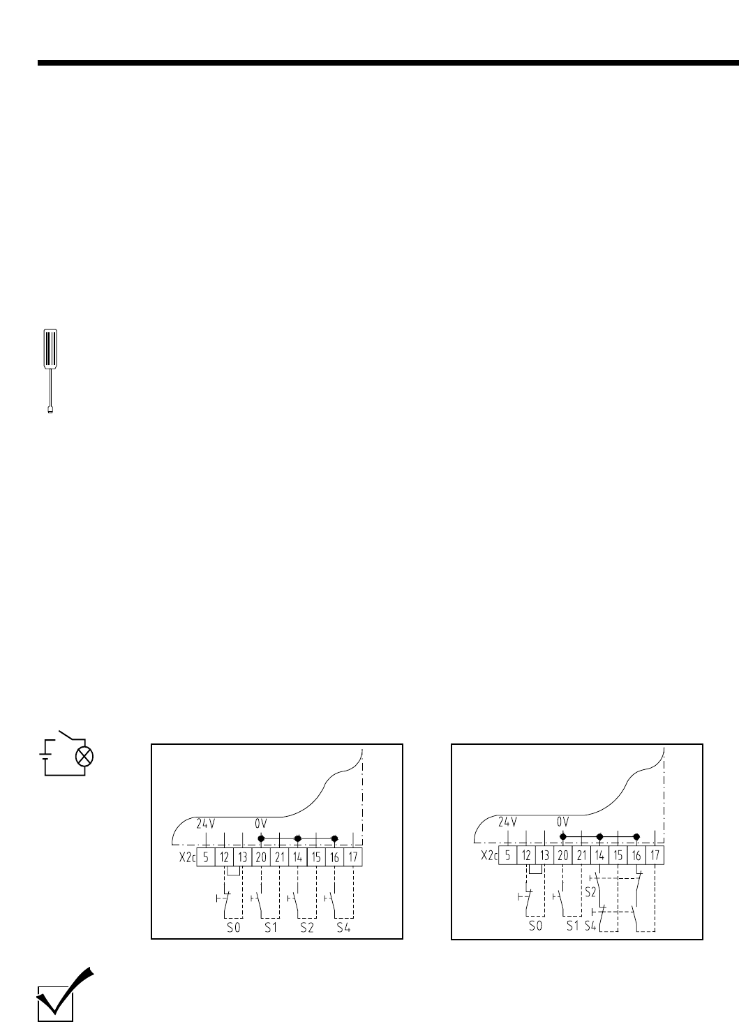
Static current circuit (control elements) is
open.
Static current circuit (door leaf) is open.
Electronic aerial is disconnected.
Hand transmitter incorrectly coded.
Flat battery.
Power limit set too sensitive.
Door operation too sluggish.
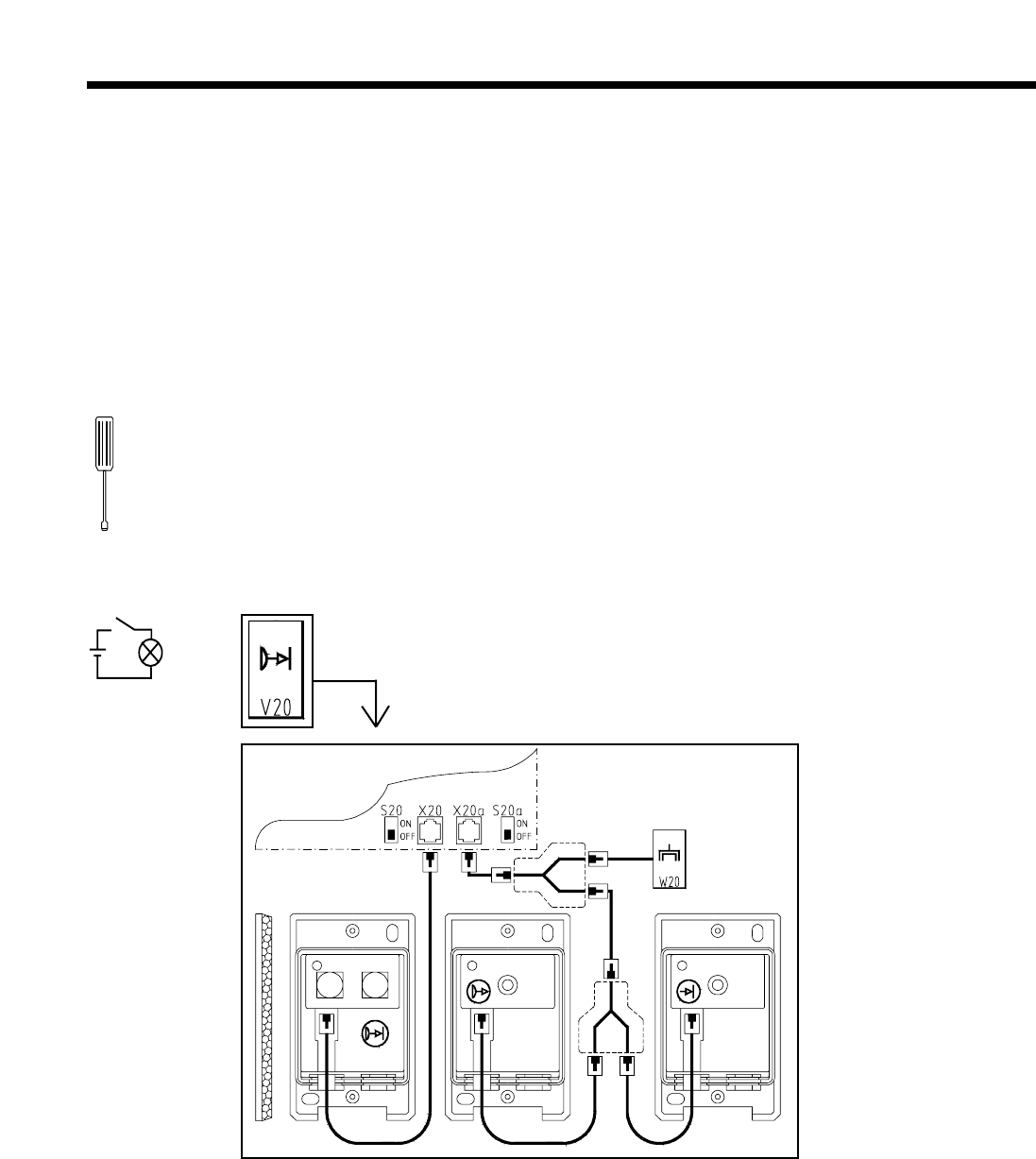
S20 programming switch at OFF,
but no photocell connected.
S20a programming switch at OFF, but no
photocell connected.
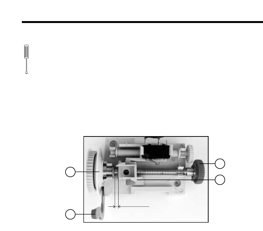
Reference point switch at wrong setting.
Optosensor is disconnected.
Coiled cable defective.
Optosensors are not in the bottom door seal
or are defective.
Bottom door seal is deformed.
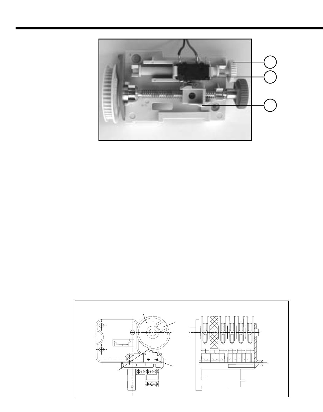
RPM sensor defective.
Fault in the control unit.
Remedy
Check voltage. Check main fuses in the electric distribution, 4 amp
fuse in the control unit and the mains plug connection.
Return the emergency hand chain to the home position
(see Operllation Instructions).
Engage the maintenance release or quick release.
Allow the motor to cool down.
Unlock control unit (blue mark).
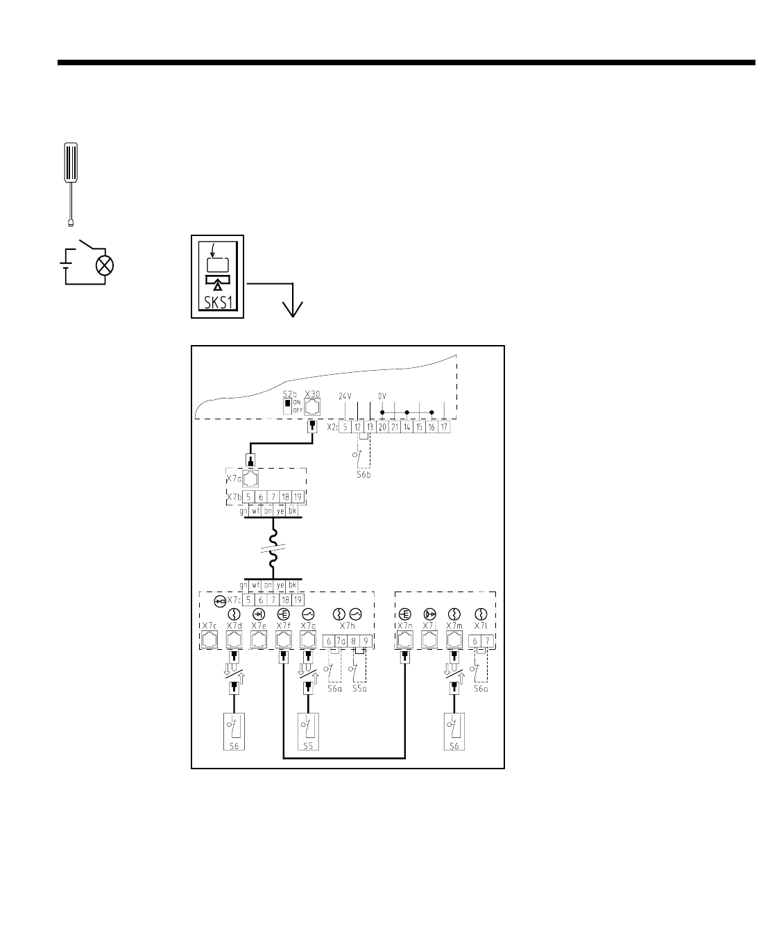
Insert short-circuit plug or control element plug into X10 socket.
Connect the STOP button to terminals 13 and 13.
Check cable slack switch, wicket door switch and cable safety switch
Coonect aerial (see page 17).
Recode the hand transmitter (see page 17).
Insert new 9V battery ( IEC 6F22).
Make power limit less sensitive (see page 11).
Door system requires maintenance (lubrication or similar).
Switch over S20 programming switch or connect photocell.
Switch over S20a programming switch or connect photocell.
Alter reference point setting (see page 9).
Connect optosensor (see page 13).
Check coiled cable and connections.
Check that optosensors are correctly installed or, if necessary,
replace.
Align bottom door seal or, if necessary, replace.
Have drive unit checked.
Have control unit checked.
6. Appendix
6.2 Test instructions
31
6. Appendix
6.3 Function and error messages in the display
Displayed Explanation
0 STOP button actuated, static current circuit broken
1 IMPULSE button actuated
2 OPEN button actuated
3 OPEN closing edge safety device actuated
4 CLOSE button actuated
5 CLOSE closing edge safety device actuated
6 Site photocell actuated
7 Programming terminated
8 Faulty reference point impulse
9 RPM sensor defective
10 Power limit too sensitive
11 Excess travel stop
12 Faulty test unit - OPEN closing edge safety device
13 Faulty test unit - CLOSE closing edge safety device
14 Position invalid as no reference point
15 Faulty test unit - external photocell 1 (X20)
24 Faulty test unit - external photocell 2 (X20a)
29 Memory faulty
30 Control unit faulty
32 Chipcard defective
33 Automatic function switched off
32
Space for notes
Space for notes
33
Space for notes
34
35
Figures to the Control 120 - 123 control units
Overview of door and surrounding area
2 3 6 7
5 4
10
9
8
16
17 18
14
12
13
11
15
1
Control lights:
1. Voltage
2. OPEN travel limit
3. CLOSE travel limit
4. Remote control
5. Maintenance
6. OPEN power limit
7. CLOSE power limit
8. Open phase
9. Warning phase
10. HALF OPEN intermediate travel limit
11. OPEN button
12. CLOSE button
13. STOP button
14. HALF OPEN button
15. PROGRAMMING button
16. MENU SELECT button
17. Fine adjustment display
18. Multi-function display
Fig. A: Control panel
33
32
31
39
26
28
30
27
34
35
38
25
29
36 37
Plug connections:
25. X30 Closing edge safety device
(CLOSE direction)
26. X20a Electronic aerial
27. X10 External control elements
28. X20 External photocell
29. X40 Motor connection
30. X32 Closing edge safety device
(OPEN direction)
31. X5E Extension connection
32. X8b Signal light relay
33. X8a Travel limit relay
34. X8c Special function relay
35. X8d Special function relay
Connecting terminals:
39. X2c External control elements
Programming switch:
36. S20 Photocell
27. S20a Photocell
38. Chip card
Fig. B/1: Connections in the control unit (extract)
D
C
A
B
F
E
A Control panel in the control unit
B Connections in the control unit
C Connections in the door operator
D Reference point setting
E Site electric socket CEE standard 16A
F Door leaf connection
Copyright.
No part of this manual may be reproduced without our prior written approval.
We reserve the right to change details in the interests of progress.
Status: 11.2000
#8 009 836
1 - GB 36054 - M - 0.5 - 0496
35

Hulp nodig? Stel uw vraag in het forum

Spelregels

Misbruik melden

Gebruikershandleiding.com neemt misbruik van zijn services uitermate serieus. U kunt hieronder aangeven waarom deze vraag ongepast is. Wij controleren de vraag en zonodig wordt deze verwijderd.

Product:

Bijvoorbeeld antisemitische inhoud, racistische inhoud, of materiaal dat gewelddadige fysieke handelingen tot gevolg kan hebben.

Bijvoorbeeld een creditcardnummer, een persoonlijk identificatienummer, of een geheim adres. E-mailadressen en volledige namen worden niet als privégegevens beschouwd.

Spelregels forum

Om tot zinvolle vragen te komen hanteren wij de volgende spelregels:

Belangrijk! Als er een antwoord wordt gegeven op uw vraag, dan is het voor de gever van het antwoord nuttig om te weten als u er wel (of niet) mee geholpen bent! Wij vragen u dus ook te reageren op een antwoord.

Belangrijk! Antwoorden worden ook per e-mail naar abonnees gestuurd. Laat uw emailadres achter op deze site, zodat u op de hoogte blijft. U krijgt dan ook andere vragen en antwoorden te zien.

Abonneren

Abonneer u voor het ontvangen van emails voor uw Marantec Control 120 bij:


U ontvangt een email met instructies om u voor één of beide opties in te schrijven.


Ontvang uw handleiding per email

Vul uw emailadres in en ontvang de handleiding van Marantec Control 120 in de taal/talen: Engels als bijlage per email.

De handleiding is 0,75 mb groot.


U ontvangt de handleiding per email binnen enkele minuten. Als u geen email heeft ontvangen, dan heeft u waarschijnlijk een verkeerd emailadres ingevuld of is uw mailbox te vol. Daarnaast kan het zijn dat uw internetprovider een maximum heeft aan de grootte per email. Omdat hier een handleiding wordt meegestuurd, kan het voorkomen dat de email groter is dan toegestaan bij uw provider.

Stel vragen via chat aan uw handleiding

Stel uw vraag over deze PDF

Andere handleiding(en) van Marantec Control 120

Marantec Control 120 Gebruiksaanwijzing - Nederlands - 36 pagina's

Marantec Control 120 Gebruiksaanwijzing - Deutsch - 36 pagina's

Marantec Control 120 Gebruiksaanwijzing - Français - 36 pagina's


Uw handleiding is per email verstuurd. Controleer uw email

Als u niet binnen een kwartier uw email met handleiding ontvangen heeft, kan het zijn dat u een verkeerd emailadres heeft ingevuld of dat uw emailprovider een maximum grootte per email heeft ingesteld die kleiner is dan de grootte van de handleiding.

Er is een email naar u verstuurd om uw inschrijving definitief te maken.

Controleer uw email en volg de aanwijzingen op om uw inschrijving definitief te maken

U heeft geen emailadres opgegeven

Als u de handleiding per email wilt ontvangen, vul dan een geldig emailadres in.

Uw vraag is op deze pagina toegevoegd

Wilt u een email ontvangen bij een antwoord en/of nieuwe vragen? Vul dan hier uw emailadres in.


Info