742637
13
Verklein
Vergroot
Pagina terug
1/33
Pagina verder
1
Control 100, 101, 102, 103
Einbauanleitung
Fitting Instructions
Notice de Montage
Montagehandleiding
Monteringsanvisningar
Monteringsveiledning
Montagevejledning
6
D E U T S C H
1. Übersicht Basissteuerung Control 100
A Steckleiste Fernsteuerung
B Umschalter DW-Kontakt / Schließkantensicherung mit Optosensor
C Taster und Leuchtdiode Auf
D Taster und Leuchtdiode Zu
E Leuchtdiode Steuerspannung
F Taster Halt
G Steckverbindung Folientaster
H Leuchtdiode Testung
I Steckverbindung X2f Anschluß Control 200 und Control 300
J Schalter S7, S8, S18, S19, S20
K Anschlußklemme X2e Lichtschranke 24 V
L Anschlußklemme X2c Taster Auf, Zu, Halt
M Anschlußstifte X2d für zusätzliche Taster Auf, Zu, Halt
N Anschlußstifte X2a Endtaster S11, S13, S14
O Anschlußstifte X2b Schlaffseilsicherung, DW-Kontakt
P Steuersicherung F1, 80 mA max.
Q Schutzleiteranschluß
R Hauptschalter
S Anschlußklemmleiste X2 für Motoranschluß
T Anschlußklemmleiste X2 für Netzspannung
U Netzsicherung F2-F4, 6,3 A max.
V CEE-Stecker
W Umschalter S16, S17 für Digital 131
2. Farblegende
bk - schwarz bl - blau bn - braun gn/ye - grün/gelb gr - grau pk - rosa pu - violett
rd - rot wt - weiß ye - gelb
3. Schaltplan Control 100 / Control 101
DW Druckwellenkontakt
F1 Feinsicherung 80 mA
F2-F4 Hauptsicherungen 6,3 A
H1 Leuchtdiode »Steuerspannung«
H2 Leuchtdiode »Laufrichtung Auf«
H3 Leuchtdiode »Laufrichtung Zu«
H4 Leuchtdiode »Testung«
H5 Leuchtdiode »Endstellung Auf« *
H6 Leuchtdiode »Endstellung Zu« *
K1 Relais »Auf«
K2 Relais »Zu«
K2v Zeitrelais (abfallverzögert)
K3 Relais »Impuls«
K4 DW-Relais (bistabil)
K5 DW-Testrelais (bistabil)
K6 DW-Relais
K7 Relais »Halt«
K11 Wendeschütz »Auf«
K21 Wendeschütz »Zu«
KL Lichtschranke
M1 Motor mit Thermoschutz
S Hauptschalter
S0,S0a Taster »Halt« (abschließbar bei Control 101)*
S0H Taster »Halt«
S1,S1a Taster »Betrieb oder Zugtaster« *
S2,S2a Taster »Auf« *
S2A Taster »Auf«
S4, S4a Taster »Zu« *
S4Z Taster »Zu«
S5 Endtaster Schlupftür *
S6 Endtaster Schlaffseilsicherung (nur bei Wellenantrieb Dynamic)
S7 Auf - Selbsthaltung Ein / Aus
S8 Zu - Selbsthaltung Ein / Aus
S10 Endtaster »Nothandbedienung« (nur bei Wellenantrieb Dynamic)
S11 Endtaster »Auf«
S13 Endtaster »Zu«
7
S14 Endtaster »DW-UM« *
S16, S17 Programmierschalter Digital 131
S18 Programmierschalter 2. Halttaste X2d
S19 Programmierschalter Control 200/Control 300
S20 Programmierschalter Lichtschranke
S21 Umschalter DW-Kontakt / Schließkantensicherung mit Optosensor
T1 Transformator
V1 Netzteil
X1 Zuleitung 3 ~ 220 V/380 V 50 Hz
X1a Zuleitung 3 ~ 220 V 50 Hz
X2, X2a-e Anschlußklemmleiste »Basissteuerung Control 100«
X2f Steckanschluß»Basissteuerung Control 100«
X3 Klemmleiste »Antrieb«
X4 Steckleiste »Fernsteuerung«
X5 Steckanschluß »Tastaturplatine«
X7 Anschlußklemme Unfallschutzeinheit
X7a Anschlußklemme Unfallschutzeinheit Wellenantrieb Dynamic *
* falls vorhanden
Werkseitig gebrückte Klemmen, Programmierschalter
Bezeichnung Klemmleiste gebrückte Klemmen Programmierschalter
Schlaffseilsicherung X2b 6 - 7 -
1. Taster Halt S0 X2c 12 - 13 -
2. Taster Halt S0a X2d - S18
Lichtschranke KL - S20
Autom. Zulauf Control 200 X2f - S19
Ampelsteuerung Control 300 X2f - S19
Schlupftür X7a a -
Bei Anschluß der oben aufgeführten Zusatzeinrichtungen Brücken entfernen bzw. Programmierschalter in Stellung
OFF bringen.
Verkabelung Motor, Endtaster, Schließkantensicherung bauseitig.
Achtung:
Örtliche Schutzbestimmungen beachten!
Steuerspannung 24 V DC
Umschalter Selbsthaltung
S7 S8
Auf-Richtung Zu-Richtung
OFF OFF A2: Auf/Zu ohne Selbsthaltung
ON OFF A3: Auf mit Selbsthaltung Zu ohne Selbsthaltung
OFF ON A4: Auf ohne Selbsthaltung Zu mit Selbsthaltung
ON ON A6: Auf/Zu mit Selbsthaltung
Umschalter S21 Werkseitige Voreinstellung für Anschluß
Digital 131
Schließkantensicherung mit DW-Kontakt S17
Schließkantensicherung mit Optosensor S16
8
4. Anschlußplan Unfallschutzeinheit mit Optosensor
V5 Sender Optosensor
V6 Empfänger Optosensor
X7e Anschlußklemme Unfallschutzeinheit
X7d Anschlußklemme Unfallschutzeinheit Wellenantrieb Dynamic
5. Anschlußplan Control 102, Tor 1/2 Auf. / Control 103
S0 abschließbar (Control 103)
S12 Endtaster »1/2 Auf«
S15 Umschalter »Tor Auf/Tor 1/2 Auf«
X15 zus. Klemmleiste »1/2 Auf«, im Steuerungsgehäuse »Control 100«
X15a zus. Klemmleiste »Endtaster 1/2 Auf«, im Antrieb
6. Anschlußplan Drucktaster Auf-Zu-Halt, abschließbar.
H5 Kontrollampe Steuerung EIN 24 V/2 W max.
S0b Taster »Halt«
S0c Kontakt »Halt« Schlüsseltaster
S2b Taster »Auf«
S4b Taster »Zu«
7. Anschlußschaltplan potentialfreie Endtasterkontakte.
Erforderlicher Zusatzbaustein: Relaisplatine
K6a Kontakt zwischen 80 und 81 geschlossen, wenn Tor nicht zu.
Kontakt zwischen 80 und 82 geöffnet, wenn Tor nicht zu.
K7a Kontakt zwischen 84 und 85 geschlossen, wenn Tor auf.
Kontakt zwischen 84 und 86 geöffnet, wenn Tor auf.
X2f Steckanschluß »Basissteuerung Control 100«
X6 Anschlußklemmleiste »Relaisplatine«
X6a , X6b Steckanschluß »Relaisplatine«
8. Anschlußplan Lichtschranke als Unfallschutz.
Wenn Lichtstrahl unterbrochen, ist Kontakt 1-3 geöffnet. Programmierschalter S20 auf OFF.
KL Lichtschranke
9. Verkabelung Basissteuerung Control 100 mit Induktionsschleifendetektor Control 400, Art. Nr.: 564 022
Impulsgabe "Tor Auf" durch Induktionsschleife
X9 Klemmleiste »Induktionsschleifendetektor Control 400«
10. Verkabelung Basissteuerung Control 100 mit automatischem Zulauf Control 200 (Art. Nr.: 564 007),
Induktionsschleifendetektor Control 400, Zugtaster und Lichtschranke KL. Impulsgabe "Tor Auf" durch
Induktionsschleife und Zugtaster. "Tor Zu" durch automatischem Zulauf Control 200. Programmierschalter S19 in
Basissteuerung Control 100 auf "OFF".
Control 210 Wochenzeitschaltuhr Automatik Ein/Aus (falls vorhanden)
F1b Sicherung 4 A max.
H41, H42 Ampel (Einfahrt/Ausfahrt)
K41 Relais »Blinkt«
K43 Relais »Stop«
K44 Relais »Impuls«
S32 Schalter Automatik Ein/Aus (falls vorhanden)
S33 Taster »Impuls« mit automatischem Zulauf
X8, X8b Anschlußklemmleiste »Control 200«
X8a Steckanschluß »Control 200«
X9 Klemmleiste »Induktionsschleifendetektor Control 400«
a Bei Einbau der Lichtschranke Brücke a entfernen
11. Verkabelung Basissteuerung Control 100 mit Ampelsteuerung Control 300, Induktionsschleifendetektor Control 400,
Zugtaster und Lichtschranke KL. Impulsgabe über Induktionsschleife und Zugtaster. Fahrtrichtungsregelung durch
Ampelsteuerung Control 300 Art. Nr.: 564 020.
Programmierschalter S19 in Basissteuerung Control 100 auf "OFF".
F1b Feinsicherung 4 A max
H40a LED »Tor Auf«
H40b LED »Tor nicht Zu«
H41 Ampel »Ausfahrt rot«
H42 Ampel »Ausfahrt grün«
H43 Ampel »Einfahrt rot«
9
H44 Ampel »Einfahrt grün«
K41 Relais Ampel
K42a Relais Ampel »Ausfahrt«
K42b Relais Ampel »Einfahrt«
K43 Relais »Stop«
K44 Relais »Impuls«
S30 Taster »Impuls Ausfahrt«
S31 Taster »Impuls Einfahrt«
S32 Schalter Automatik »Ein / Aus« (falls vorhanden)
WZ Wochenzeitschaltuhr (falls vorhanden)
X8, X8b Klemmleiste »Control 300«
X8a Steckanschluß »Control 300«
X9 Klemmleiste »Induktionsschleifendetektor Control 400«
10
E N G L I S H
1. Overview Control 100 base control unit
A Plug-in strip remote control
B Change-over switch airswitch contact/closing edge safety device with optosensor
C Push button and LED „open“
D Push button and LED „close“
E LED control voltage
F Push button „stop“
G Plug-in connection membrane key
H LED test unit
I Plug-in connection X2f connection Control 200 and Control 300
J Switch S7,S8,S18,S19,S20
K Connecting terminal X2e photocell 24 V
L Connecting terminal X2c button „open“, „close“, „stop“
M Connection pins X2d for extra button „open, „close“, „stop“
N Connection pins X2a limit switch S11,S13,S14
O Connection pins X2b cable slack device, airswitch (DW) contact
P Control fuse F1, 80mA max.
Q Earthing point
R Main switch
S Connecting terminal block X2 for motor connection
T Connecting terminal block X2 for mains voltage
U Mains fuse F2-F4, 6.3 A max.
V CEE plug
W S16, S17 change-over switch for Digital 131
2. Colour code
bk - black bl - blue bn - brown gn/ye - green/yellow gr - grey pk - pink pu - purple
rd - red wt - white ye - yellow
3. Circuit diagram Control 100/Control 101
DW Airswitch contact
F1 Fuse 80 mA
FS-F4 Main fuses 6.3 A
H1 LED „control voltage“
H2 LED „direction open“
H3 LED „direction close“
H4 LED „test unit“
H5 LED „final position open“
H6 LED „final position close“
K1 Relay „open“
K2 Relay „close“
K2v Time lag relay (slow-release)
K3 Relay „pulse“
K4 Airswitch (DW) relay (bistable)
K5 Airswitch (DW) test relay (bistable)
K6 Airswitch (DW) relay
K7 Relay „stop“
K11 Helix contactor „close“
K21 Helix contactor „open“
KL Photocell
M1 Motor with thermal protection
S Main switch
S0,S0a „stop“ button (with Control 101 lockable) *
S0H „stop“ button
S1,S1a „operate or pull“ button
S2,S2a „open“ button
S2A „open“ button
S4,S4a „close“ button
S4Z „close“ button
S5 Limit switch „wicket door“
S6 Limit switch „cable slack device“ (only with „Dynamic“ shaft drive)
S7 „open“ - self hold ON/OFF
S8 „close“ - self hold ON/OFF
S10 Limit switch „emergency hand chain“ (only with „Dynamic“ shaft drive)
S11 Limit switch „open“
11
S13 Limit switch „close“
S14 Limit switch „DW-UM“
S16, S17 Programming „Digital 131”
S18 Programming switch 2nd stop switch X2d
S19 Programming switch Control 200/Control 300
S20 Programming switch photocell
S21 Change-over airswitch contact/closing edge safety device with optosensor
T1 Transformer
V1 Mains supply circuit
X1 Power cable 3 - 220 V/380 V 50 Hz
X1a Power cable 3 - 220 V 50 Hz
X2,X2a-e Connecting terminal block „Control 100 base control unit“
X2f Plug-in connection „Control 100 base control unit“
X3 Terminal block „drive“
X4 Plug-in stip „remote control“
X5 Plug-in connection „keypad circuit board“
X7 Connecting terminal safety device
X7a Connecting terminal safety device „Dynamic“ shaft drive*
* if included
Factory-bridged terminals, programming switch
Designation Terminal block Bridged terminals Programming switch
Cable slack device X2b 6 - 7 -
1st „stop“ switch S0 X2c 1 2 - 13 -
2nd „stop“ switch S0a X2d - S18
Photocell KL - S20
Autom. timed return
Control 200 X2f - S19
Traffic light Control 300 X2f - S19
Wicket door X7a a -
On connecting the above listed additional devices, remove bridges or switch programming switch to OFF.
Cabling for motor, limit switches, closing edge safety device to be carried out on site.
Important:
Observe local safety regulations!
Control voltage 24 V DC
Change-over switch self-hold
S7 S8
„open“ direction „close“ direction
OFF OFF A2: open/close without self-hold
ON OFF A3: open with self-hold, close without self-hold
OFF ON A4: open without self-hold, close with self-hold
ON ON A6: open/close with self-hold
Change-over switch S21 Pre-set for „Digital 131“ at the
factory
closing edge safety device with airswitch (DW) contact S17
closing edge safety device with optosensor S16
12
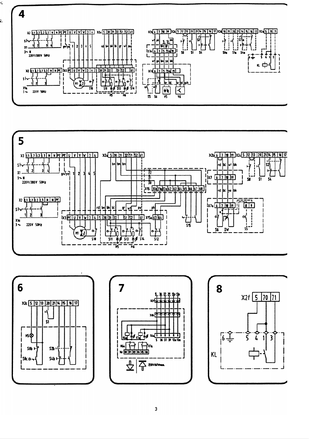
4. Connecting plan for safety device with optosensor
V5 Optosensor transmitter
V6 Optosensor receiver
X7e Connecting terminal for safety device
X7d Connecting terminal for safety device with Dynamic shaft drive
5. Connecting plan for Control 102, door 1/2 open/Control 103
S0 lockable (Control 103)
S12 Limit switch „1/2 open“
S15 Change-over switch „door open/door 1/2 open“
X15 Extra terminal block „1/2 open“ in „Control 100“ contol box
X15a Extra terminal block „limit switch 1/2 open“, in drive operator
6. Connecting plan for lockable push button open-close-stop
H5 Indicator lamp control ON 24 V/2 W max.
S0b „stop“ button
S0c „stop“ contact for key switch
S2b „open“ button
S4b „close“ button
7. Connecting plan for potential-free limit switch contacts
(Relay circuit board required in addition).
K6a Contact between 80 and 81 closed, when door closing.
Contact between 80 and 82 opened, when door closing.
K7a Contact between 84 and 85 closed, when door open
Contact between 84 and 86 opened, when door open
X2f Plug-in connection „Control 100 base control unit“
X6 Connecting terminal block „relay circuit board“
X6a, X6b Plug-in connection „relay circuit board“
8. Connecting plan for photocell as safety device
When light beam is interrupted, contacts 1-3 open. Programming switch S20 must be at OFF position.
KLphotocell
9. Wiring: Control 100 base control unit with Control 400 induction loop detector, code no. 564 022.
Pulse „open“ given through induction loop
X9 Terminal block „Control 200 induction loop detector“
10. Wiring: Control 100 base control unit with Control 200 automatic timed return, code no. 564 007, Control 400
induction loop detector, pull button and photocell KL. „Open“ pulse given through induction loop and pull button,
„close“ pulse given through Control 200 automatic return. Programming switch S19 in Control 100 base control unit
must be at „OFF“ position.
Control 210 Automatic week timer ON/OFF (if included)
F1b Fuse 4 A max.
H41, H42 Light (Entry/Exit)
K41 „flashing“ relay
K43 „stop“ relay
K44 „impulse“ relay
S32 Automatic switch ON/OFF (if included)
S33 „pulse“ button with automatic timed return
X8,X8b Connecting terminal block „Control 200“
X8a Plug-in connection „Control 200“
X9 Terminal block 400 induction loop detector“
a On fitting photocell, remove bridge a.
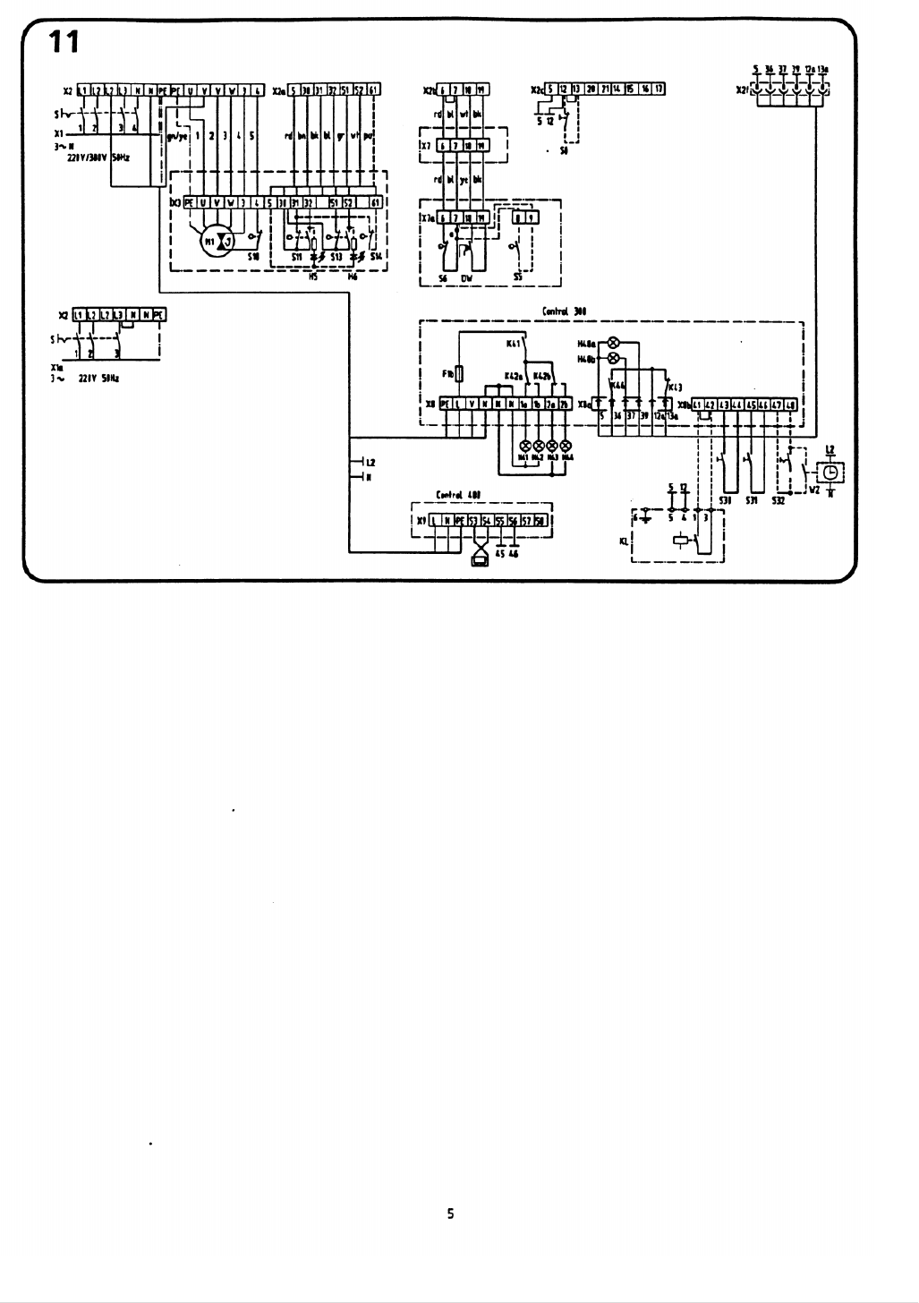
11. Wiring: Control 100 base control unit with Control 300 traffic light controls, Control 400 induction loop detector,
pull button and photocell KL. Pulse given via induction loop and pull button.
Direction of travel regulated via Control 300 traffic light controls, code no. 564 020.
Programming switch S19 in Control 100 base control unit must be at „OFF“ position.
F1b Fuse 4 A max
H40a LED „open door“
H40b LED „door not closed“
H41 Light „exit red“
H42 Light „exit green“
H43 Light „entry red“
13
H44 Light „ entry green“
K41 Relay light
K42a Relay light „exit“
K42b Relay light „entry“
K43 Relay „stop“
K44 Relay „pulse“
S30 Button „pulse exit“
S31 Button „pulse entry“
S32 Automatic „ON/OFF“ (if included)
WZ Week timer (if included)
X8,X8b Terminal block „Control 300“
X8a Plug-in connection „Control 300“
X9 Terminal block „Control 400 induction loop detector“
13

Hulp nodig? Stel uw vraag in het forum

Spelregels

Misbruik melden

Gebruikershandleiding.com neemt misbruik van zijn services uitermate serieus. U kunt hieronder aangeven waarom deze vraag ongepast is. Wij controleren de vraag en zonodig wordt deze verwijderd.

Product:

Bijvoorbeeld antisemitische inhoud, racistische inhoud, of materiaal dat gewelddadige fysieke handelingen tot gevolg kan hebben.

Bijvoorbeeld een creditcardnummer, een persoonlijk identificatienummer, of een geheim adres. E-mailadressen en volledige namen worden niet als privégegevens beschouwd.

Spelregels forum

Om tot zinvolle vragen te komen hanteren wij de volgende spelregels:

Belangrijk! Als er een antwoord wordt gegeven op uw vraag, dan is het voor de gever van het antwoord nuttig om te weten als u er wel (of niet) mee geholpen bent! Wij vragen u dus ook te reageren op een antwoord.

Belangrijk! Antwoorden worden ook per e-mail naar abonnees gestuurd. Laat uw emailadres achter op deze site, zodat u op de hoogte blijft. U krijgt dan ook andere vragen en antwoorden te zien.

Abonneren

Abonneer u voor het ontvangen van emails voor uw Marantec Control 101 bij:


U ontvangt een email met instructies om u voor één of beide opties in te schrijven.


Ontvang uw handleiding per email

Vul uw emailadres in en ontvang de handleiding van Marantec Control 101 in de taal/talen: Nederlands, Duits, Engels, Frans, Deens, Zweeds, Noors als bijlage per email.

De handleiding is 0,91 mb groot.


U ontvangt de handleiding per email binnen enkele minuten. Als u geen email heeft ontvangen, dan heeft u waarschijnlijk een verkeerd emailadres ingevuld of is uw mailbox te vol. Daarnaast kan het zijn dat uw internetprovider een maximum heeft aan de grootte per email. Omdat hier een handleiding wordt meegestuurd, kan het voorkomen dat de email groter is dan toegestaan bij uw provider.

Stel vragen via chat aan uw handleiding

Stel uw vraag over deze PDF

Uw handleiding is per email verstuurd. Controleer uw email

Als u niet binnen een kwartier uw email met handleiding ontvangen heeft, kan het zijn dat u een verkeerd emailadres heeft ingevuld of dat uw emailprovider een maximum grootte per email heeft ingesteld die kleiner is dan de grootte van de handleiding.

Er is een email naar u verstuurd om uw inschrijving definitief te maken.

Controleer uw email en volg de aanwijzingen op om uw inschrijving definitief te maken

U heeft geen emailadres opgegeven

Als u de handleiding per email wilt ontvangen, vul dan een geldig emailadres in.

Uw vraag is op deze pagina toegevoegd

Wilt u een email ontvangen bij een antwoord en/of nieuwe vragen? Vul dan hier uw emailadres in.


Info