110245
1
Verklein
Vergroot
Pagina terug
1/16
Pagina verder
GB
Portable Cut-Off Instruction Manual
F
Tronçonneuse portative Manuel d’instructions
D
Trennschleifmaschine Betriebsanleitung
I
Troncatrice portatile Istruzioni per l’uso
NL
Afkortslijpmachine Gebruiksaanwijzing
E
Tronzadora Manual de instrucciones
P
Cortadora de disco abrasivo Manual de instruções
DK
Hurtigafkorter Brugsanvisning
S
Portabel kapmaskin Bruksanvisning
N
Bærbar kappemaskin Bruksanvisning
FIN
Kannettava kulmasaha Käyttöohje
GR Φορητς kφτης Οδηγίες χρήσεως
2414B
2
12
34
56
78
18
17
15
16
3
13
14
14
13
3
13
14
11
12
45 mm
10
9
4
5
8
6
7
1
2
4
3
3
910
11 12
13 14
15 16
13
22
19
20
21
29
28
30
28
31
33
32
34
35
25
24
13
23
26
27
4
17 18
19
36
38
37
5
Symbols
The followings show the symbols used for the tool. Be sure that you understand their meaning before use.
Symboles
Nous donnons ci-dessous les symboles utilisés pour l’outil. Assurez-vous que vous en avez bien compris la significa-
tion avant d’utiliser l’outil.
Symbole
Die folgenden Symbole werden für die Maschine verwendet. Machen Sie sich vor der Benutzung unbedingt mit ihrer
Bedeutung vertraut.
Simboli
Per questo utensile vengono usati i simboli seguenti. Bisogna capire il loro significato prima di usare l’utensile.
Symbolen
Voor dit gereedschap worden de volgende symbolen gebruikt. Zorg ervoor dat u de betekenis van deze symbolen
begrijpt alvorens het gereedschap te gebruiken.
Símbolos
A continuación se muestran los símbolos utilizados con esta herramienta. Asegúrese de que entiende su significado
antes de usarla.
Símbolos
O seguinte mostra os símbolos utilizados para a ferramenta. Certifique-se de que compreende o seu significado antes
da utilização.
Symboler
Nedenstående symboler er anvendt i forbindelse med denne maskine. Vær sikker på, at De har forstået symbolernes
betydning, før maskinen anvendes.
Symboler
Det följande visar de symboler som används för den här maskinen. Se noga till att du förstår deras innebörd innan
maskinen används.
Symbolene
lgende viser de symblene som brukes for maskinen. Det er viktig å forstå betydningen av disse før maskinen tas i
bruk.
Symbolit
Alla on esitetty koneessa käytetyt symbolit. Opettele näiden merkitys, ennen kuin käytät konetta.
Σύµβολα
Τα ακλουθα δείχνουν τα σύµβολα που χρησιµοποιούνται για το µηχάνηµα. Βεβαιωθείτε τι καταλαβαίνετε
τη σηµασία τους πριν απ τη χρήση.
Read instruction manual.
Lire le mode d’emploi.
Bitte Betriebsanleitung lesen.
Leggete il manuale di istruzioni.
Lees de gebruiksaanwijzing.
Lea el manual de instrucciones.
Leia o manual de instruções.
Læs brugsanvisningen.
Läs bruksanvisningen.
Les bruksanvisingen.
Katso käyttöohjeita.
∆ιαβάστε τις οδηγίες χρήσης.
DOUBLE INSULATION
DOUBLE ISOLATION
DOPPELT SCHUTZISOLIERT
DOPPIO ISOLAMENTO
DUBBELE ISOLATIE
DOBLE AISLAMIENTO
DUPLO ISOLAMENTO
DOBBELT ISOLATION
DUBBEL ISOLERING
DOBBEL ISOLERING
KAKSINKERTAINEN ERISTYS
∆ΙΠΛΗ ΜΟΝΩΣΗ
6
ENGLISH
Explanation of general view
1 Safety guide
2 Shaft lock
3 Socket wrench
4 Cut-off wheel
5 Inner flange
6O-ring
7Spindle
8 Ring
9 Outer flange
10 Hex bolt
11 Screw
12 Spark guard
13 Guide plate
14 Hex bolts
15 Vise plate
16 Vise nut
17 Vise handle
18 Spacer block
19 Straight piece of wood (Spacer)
20 Over 190 mm long
21 Over 45 mm wide
22 Over 65 mm wide
23 Diameter of workpiece
24 Spacer block
25 Vise
26 Width of spacer block
27 Blocks
28 Switch trigger
29 Lock-off button
30 Lock button
31 Handle
32 Uncut portion
33 Workpiece
34 Wing bolt
35 Under cover
36 Limit mark
37 Screwdriver
38 Brush holder cap
SPECIFICATIONS
Model 2414B
Wheel diameter ...................................................................................................................................................355 mm
Hole diameter .....................................................................................................................................................25.4 mm
No load speed (min
-1
) ............................................................................................................................................ 3,800
Dimensions (L x W x H)
With under cover .............................................................................................................500 mm x 280 mm x 620 mm
Net weight
For tools with European type safety guide and under cover...............................................................................18.7 kg
Due to our continuing program of research and devel-
opment, the specifications herein are subject to change
without notice.
Note: Specifications may differ from country to country.
Power supply
The tool should be connected only to a power supply of
the same voltage as indicated on the nameplate, and can
only be operated on single-phase AC supply. They are
double-insulated in accordance with European Standard
and can, therefore, also be used from sockets without
earth wire.
For public low-voltage distribution systems of
between 220 V and 250 V
Switching operations of electric apparatus cause voltage
fluctuations. The operation of this device under unfavor-
able mains conditions can have adverse effects to the
operation of other equipment. With a mains impedance
equal or less than 0.26 Ohms it can be presumed that
there will be no negative effects.
The mains socket used for this device must be protected
with a fuse or protective circuit breaker having slow trip-
ping characteristics.
Safety hints
For your own safety, please refer to the enclosed safety
instructions.
ADDITIONAL SAFETY RULES
ENB066-1
1. Wear protective glasses. Also wear hearing pro-
tection during extended periods of operation.
2. Use only wheels recommended by the manufac-
turer which have a maximum operating speed at
least as high as “No Load RPM” marked on the
tool’s nameplate. Use only fiberglass-reinforced
cut-off wheels.
3. Check the wheel carefully for cracks or damage
before operation. Replace cracked or damaged
wheel immediately.
4. Secure the wheel carefully.
5. Use only flanges specified for this tool.
6. Be careful not to damage the spindle, flanges
(especially the installing surface) or bolt, or the
wheel itself might break.
7. Keep guards in place and in working order.
8. Hold the handle firmly.
9. Keep hands away from rotating parts.
10. Make sure the wheel is not contacting the work-
piece before the switch is turned on.
11. Before using the tool on an actual workpiece, let
it simply run for several minutes first. Watch for
flutter or excessive vibration that might be
caused by poor installation or a poorly balanced
wheel.
12. Watch out for flying sparks when operating.
They can cause injury or ignite combustible
materials.
7
13. Remove material or debris from the area that
might be ignited by sparks. Be sure that others
are not in the path of the sparks. Keep a proper,
charged fire extinguisher closely available.
14. Use the cutting edge of the wheel only. Never
use side surface.
15. If the wheel stops during the operation, makes
an odd noise or begins to vibrate, switch off the
tool immediately.
16. Always switch off and wait for the wheel to come
to a complete stop before removing, securing
workpiece, working vise, changing work posi-
tion, angle or the wheel itself.
17. Do not touch the workpiece immediately after
operation; it is extremely hot and could burn
your skin.
18. Store wheels in a dry location only.
SAVE THESE INSTRUCTIONS.
OPERATING INSTRUCTIONS
Removing or installing cut-off wheel
Important:
Always be sure that the tool is switched off and
unplugged before removing or installing the wheel.
1. To remove the wheel, raise the safety guide. Press
the shaft lock so that the wheel cannot revolve and
use the socket wrench to loosen the hex bolt by turn-
ing it counterclockwise. (Fig. 1)
2. Then remove the hex bolt, outer flange and wheel.
(Fig. 2)
Note: Do not remove the inner flange, ring and
O-ring.
3. To install the wheel, follow the removal procedures in
reverse.
CAUTION:
Be sure to tighten the hex bolt securely. Insufficient
tightening of the hex bolt may result in severe injury.
Use the socket wrench provided to help assure proper
tightening.
Always use only the proper inner and outer flanges
which are provided with this tool.
Always lower the safety guide after replacing the wheel.
Spark guard (Fig. 3)
The spark guard is factory-installed with its lower edge
contacting the base. Before operation, loosen the screw
and raise the spark guard so that its lower edge will be
positioned approx. 45 mm above the workbench or floor
surface.
Otherwise sparks may fly around operation area.
Interval between vise and guide plate (Fig. 4 & 5)
The original spacing or interval between the vise and the
guide plate is 0 170 mm. If your work requires wider
spacing or interval, proceed as follows to change the
spacing or interval.
Remove the two hex bolts which secure the guide plate.
Move the guide plate as shown in Fig. 5 and secure it
using the hex bolts. The following interval settings are
possible:
35–205mm
70–240mm
CAUTION:
Remember that narrow workpieces may not be secured
safely when using the two, wider interval settings.
Setting for desired cutting angle (Fig. 6)
To change the cutting angle, loosen the two hex bolts
which secure the guide plate. Move the guide plate to the
desired angle ( 45°) and tighten the hex bolts
securely.
CAUTION:
Never perform miter cuts when the guide plate is set at
the 35 205 mm or 70 240 mm position.
Securing workpieces
By turning the vise handle counterclockwise and then
flipping the vise nut to the left, the vise is released from
the shaft threads and can be moved rapidly in and out. To
grip workpieces, push the vise handle until the vise plate
contacts the workpiece. Flip the vise nut to the right and
then turn the vise handle clockwise to securely retain the
workpiece. (Fig. 7)
CAUTION:
Always set the vise nut to the right fully when securing
the workpiece. Failure to do so may result in insufficient
securing of the workpiece. This could cause the work-
piece to be ejected or cause a dangerous breakage of
the wheel.
When the cut-off wheel has worn down considerably, use
a spacer block of sturdy, non-flammable material behind
the workpiece as shown in Fig. 8. You can more effi-
ciently utilize the worn wheel by using the mid point on
the periphery of the wheel to cut the workpiece.
When cutting workpieces over 65 mm wide at an angle,
attach a straight piece of wood (spacer) over 190 mm
long x 45 mm wide to the guide plate as shown in Fig. 9.
Attach this spacer with screws through the holes in the
guide plate.
If you use a spacer block which is slightly narrower than
the workpiece as shown in Fig.10, you can also utilize
the wheel economically.
Long workpieces must be supported by blocks of non-
flammable material on either side so that it will be level
with the base top. (Fig. 11)
8
Switch action
CAUTION:
Before plugging in the tool, always check to see that the
switch trigger actuates properly and returns to the “OFF”
position when released.
For tools with lock-off button (Fig. 12)
To prevent the trigger from being accidentally pulled, a
lock-off button is provided. To start the tool, press in the
lock-off button and pull the trigger. Release the trigger to
stop.
For tools with lock button (Fig.13)
To start the tool, simply pull the trigger. Release the trig-
ger to stop. For continuous operation, pull the trigger and
then push in the lock button. To stop the tool from the
locked position, pull the trigger fully, then release it.
Operation
Hold the handle firmly. Switch on the tool and wait until
the wheel attains full speed before lowering gently into
the cut. When the wheel contacts the workpiece, gradu-
ally bear down on the handle to perform the cut. When
the cut is completed, switch off the tool and WAIT UNTIL
THE WHEEL HAS COME TO A COMPLETE STOP
before returning the handle to the fully elevated position.
CAUTION:
Proper handle pressure during cutting and maximum cut-
ting efficiency can be determined by the amount of
sparks that is produced while cutting. Your pressure on
the handle should be adjusted to produce the maximum
amount of sparks. Do not force the cut by applying exces-
sive pressure on the handle. Reduced cutting efficiency,
premature wheel wear, as well as, possible damage to
the tool, cut-off wheel or workpiece may result.
Cutting capacity
Max. cutting capacity varies depending upon the cutting angle and workpiece shape. Applicable wheel
diameter: 355 mm
Tool head slide system
The tool head slides back toward you approx. 17 mm when you pull the handle. This system is convenient for the fol-
lowing applications.
1. When cutting thick pipes or bars: (Fig. 14)
Move the handle back and forth to slide the tool head. This will help increase cutting efficiency and prevent wheel
loading.
2. When cutting channels or angles: (Fig. 15)
If a portion of the workpiece near you is left uncut, pull the handle. The tool head slides back and the wheel cuts
the remaining uncut portion. If the uncut portion cannot be cut even by using this method, use a spacer block as
explained above.
For tools with the under cover (Fig. 16)
To remove the collected dust from the under cover, place
the tool with its side up and pull the under cover open
after removing the wing bolt as shown in the figure. Be
sure to close and secure the under cover with the wing
bolt after the removal of dust.
Carrying the tool (Fig. 17)
Fold down the tool head to the position where you can
attach the chain to the hook on the handle.
MAINTENANCE
CAUTION:
Always be sure that the tool is switched off and
unplugged before carrying out any work on the tool.
Replacement of carbon brushes (Fig. 18 & 19)
Replace carbon brushes when they are worn down to the
limit mark. Both identical carbon brushes should be
replaced at the same time.
To maintain product safety and reliability, repairs, mainte-
nance or adjustment should be carried out by a Makita
Authorized Service Center.
Workpiece
shape
Cutting
angle
90° 115 mm 120 mm
115mmx142mm
102mmx197mm
70 mm x 240 mm
139 mm
45° 115 mm 106 mm 115 mm x 102 mm 100 mm
A
A
A x B B
A
A
A
19
NEDERLANDS
Verklaring van algemene gegevens
1 Veiligheidskap
2 Asvergrendeling
3 Dopsleutel
4 Afkortschijf
5 Binnen fles
6 O-ring
7As
8 Ring
9 Buiten fles
10 Zeskantbout
11 Schroef
12 Vonkscherm
13 Geleideplaat
14 Zeskantbouten
15 Klemplaat
16 Klemmoer
17 Klemhendel
18 Afstandsstuk
19 Recht stuk hout (Afstandsstuk)
20 Langer dan 190 mm
21 Breder dan 45 mm
22 Breder dan 65 mm
23 Diameter van werkstuk
24 Afstandsstuk
25 Klemschroef
26 Breedte van afstandsstuk
27 Blokjes
28 Trekschakelaar
29 Ontgrendelknop
30 Vastzetknop
31 Handgreep
32 Niet afgesneden gedeelte
33 Werkstuk
34 Vleugelbout
35 Onderkap
36 Limietaanduiding
37 Schroevedraaier
38 Koolborsteldop
TECHNISCHE GEGEVENS
Model 2414B
Diameter schijf .....................................................................................................................................................355 mm
Diameter asgat ...................................................................................................................................................25,4 mm
Toerental onbelast (min
-1
) .......................................................................................................................................3 800
Afmetingen (L x B x H)
Met onderkap...................................................................................................................500 mm x 280 mm x 620 mm
Netto gewicht
Voor gereedschap met Europees type veiligheidskap en onderkap.................................................................. 18,7 kg
In verband met ononderbroken research en ontwikke-
ling behouden wij ons het recht voor bovenstaande
technische gegevens te wijzigen zonder voorafgaande
kennisgeving.
Opmerking: De technische gegevens kunnen van land
tot land verschillen.
Stroomvoorziening
De gereedschap mag alleen worden aangesloten op een
stroombron van hetzelfde voltage als aangegeven op de
naamplaat, en kan alleen op enkel-fase wisselstroom
worden gebruikt. De gereedschap is dubbel-geïsoleerd
volgens de Europese standaard en kan derhalve ook op
een niet-geaard stopcontact worden aangesloten.
Voor openbare laagspanningsverdeelsystemen van
tussen 220 V en 250 V
Schakelbedieningen van elektrische toestellen veroorza-
ken spanningsschommelingen. De bediening van dit
gereedschap onder ongunstige lichtnetomstandigheden
kan een nadelige invloed hebben op de bediening van
andere apparatuur. Het kan worden aangenomen dat er
geen negatieve effecten zullen zijn wanneer de netimpe-
dantie gelijk is aan of minder is dan 0,26 Ohm.
Het stopcontact dat voor dit gereedschap wordt gebruikt,
moet beveiligd zijn door een zekering of een stroomon-
derbreker met trage afschakelkarakteristieken.
Veiligheidswenken
Voor uw veiligheid dient u de bijgevoegde Veiligheids-
voorschriften nauwkeurig op te volgen.
AANVULLENDE
VEILIGHEIDSVOORSCHRIFTEN
1. Draag een beschermbril. Draag ook oorbes-
chermers bij langdurige werkzaamheden.
2. Gebruik uitsluitend slijpschijven die door de fab-
rikant worden aanbevolen en waarvan het maxi-
maal bedrijfstoerental minstens even hoog is als
het “No Load RPM” (toerental onbelast) dat op
de naamplaat van het gereedschap is vermeld.
Gebruik uitsluitend afkortschijven die met glas-
vezel zijn versterkt.
3. Alvorens met de werkzaamheid te beginnen, de
schijf zorgvuldig controleren op barsten of bes-
chadiging. Vervang een gebarsten of beschad-
igde schijf onmiddellijk.
4. Zet de schijf zorgvuldig vast.
5. Gebruik uitsluitend de voor dit gereedschap
voorgeschreven flenzen.
6. Zorg ervoor dat u de as, de flenzen (vooral hun
montagevlak) of de bout niet beschadigt,
aangezien de schijf zelf dan kan breken.
7. Houd de beschermingen op hun plaats en in
goede werkconditie.
8. Houd de handgreep stevig vast.
9. Houd uw handen uit de buurt van draaiende
onderdelen.
10. Zorg ervoor dat de schijf het werkstuk niet raakt
alvorens het gereedschap in te schakelen.
20
11. Laat het gereedschap een paar minuten draaien
alvorens het op een werkstuk te gebruiken. Con-
troleer het op trillingen of overmatige vibraties
die door een verkeerde installatie of een slecht
gebalanceerde schijf kunnen worden vero-
orzaakt.
12. Pas gedurende de werking op voor rondvlieg-
ende vonken. Deze kunnen letsel veroorzaken of
ontvlambaar materiaal doen ontbranden.
13. Verwijder ontvlambaar materiaal of brokstukken
uit de werkomgeving. Zorg ervoor dat niemand
zich in de vonkenbaan bevindt. Houd een in
goede staat verkerend brandblusapparaat
gereed dicht bij de werkomgeving.
14. Gebruik uitsluitend de snijkant van de schijf en
nooit de zijkant.
15. Wanneer tijdens de werkzaamheid de schijf plot-
seling stopt, vreemde geluiden maakt of begint
te trillen, schakel dan het gereedschap onmid-
dellijk uit.
16. Schakel het gereedschap altijd uit en wacht tot-
dat de schijf tot volledige stilstand is gekomen,
alvorens het werkstuk te verwijderen of vast te
zetten, de klemschroef vaster te zetten, de werk-
positie of de snijhoek te veranderen, of de schijf
te vervangen.
17. Raak het werkstuk niet aan onmiddellijk na het
werken, aangezien het dan gloeiend heet is en
brandwonden kan veroorzaken.
18. Berg de schijven uitsluitend op een droge plaats
op.
BEWAAR DEZE VOORSCHRIFTEN.
BEDIENINGSVOORSCHRIFTEN
Verwijderen of installeren van de afkortschijf
Belangrijk:
Controleer altijd of het gereedschap is uitgeschakeld en
de stekker uit het stopcontact is verwijderd alvorens de
schijf te verwijderen of te installeren.
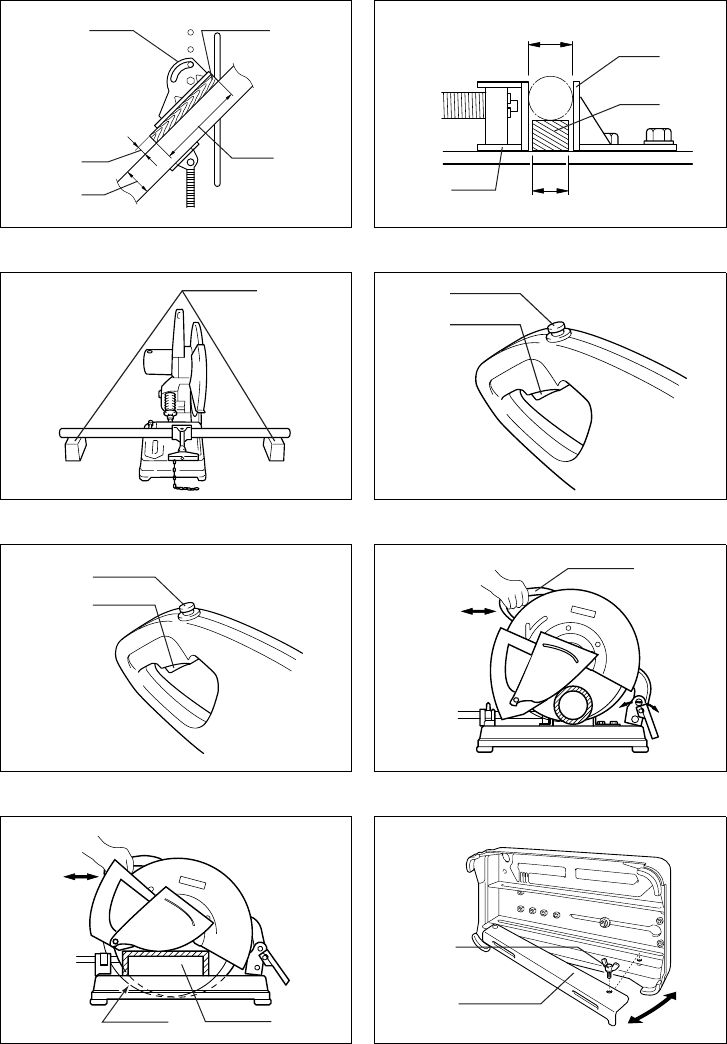
1. Om de schijf te verwijderen, eerst de veiligheidskap
omhoogbrengen. Druk de asvergrendeling in zodat
de schijf niet kan draaien. Draai dan de zeskantbout
met de dopsleutel naar links los. (Fig. 1)
2. Verwijder dan de zeskantbout, de buiten flens en de
schijf. (Fig. 2)
Opmerking: Verwijder niet de binnen flens, de ring
en de O-ring.
3. Om de schijf te installeren, volg de procedure voor
het verwijderen in omgekeerde volgorde op.
LET OP:
Zorg ervoor dat de zeskantbout goed wordt vastge-
draaid. Een te los aangetrokken zeskantbout kan oor-
zaak zijn van ernstige verwonding. Gebruik de
bijgeleverde dopsleutel om het juiste aantrekkoppel te
verzekeren.
Gebruik uitsluitend de bij deze machine geleverde bin-
nen en buiten flenzen.
Breng altijd de veiligheidskap omlaag na het vervangen
van de schijf.
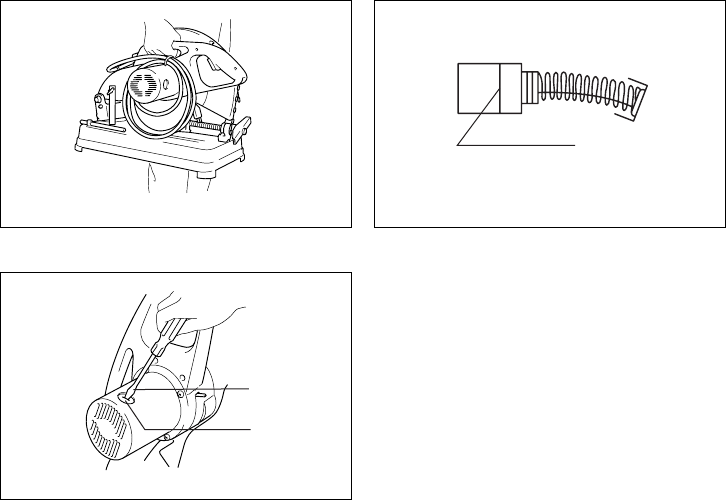
Afstellen van het vonkscherm (Fig. 3)
Het vonkscherm is in de fabriek gemonteerd met zijn
onderkant tegen het voetstuk. Vooraleer u begint te wer-
ken, draait u de schroef los en brengt u het vonkscherm
omhoog zodat zijn onderkant ongeveer 45 mm boven de
werkbank of de vloer uitsteekt, zoniet kunnen er vonken
rondvliegen.
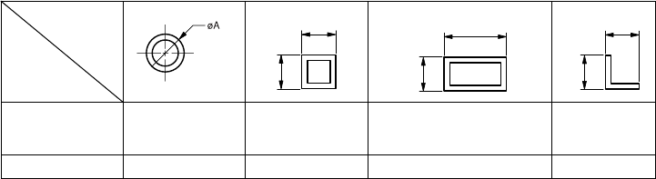
Afstand tussen klemschroef en geleideplaat
(Fig. 4 en 5)
De oorspronkelijke afstand tussen de klemschroef en de
geleideplaat is 0 170 mm. Wanneer een grotere afstand
vereist is voor uw werk, kunt u de afstand als volgt wijzi-
gen.
Verwijder de twee zeskantbouten waarmee de geleide-
plaat is vastgezet. Beweeg de geleideplaat zoals afge-
beeld in Fig. 5 en zet deze dan vast met de
zeskantbouten. De volgende afstanden zijn mogelijk:
35 205 mm
70 240 mm
LET OP:
Bij gebruik van de twee grotere afstanden, kunnen smalle
werkstukken mogelijk niet veilig worden vastgezet.
Instellen van de snijhoek (Fig. 6)
Om de snijhoek te veranderen, draait u de twee zeskant-
bouten van de geleideplaat los. Zet de geleideplaat op de
gewenste hoek (0° 45°) en draai de zeskantbouten ste-
vig vast.
LET OP:
Werk nooit met verstek wanneer de geleideplaat op 35
205 mm of 70 240 mm is ingesteld.
Vastzetten van werkstukken
Door de klemhendel linksom te draaien en dan de klem-
moer naar links te draaien, komt de klem los van de
asschroefdraad en kan hij snel in en uit worden bewo-
gen. Om een werkstuk vast te zetten, drukt u de klem-
hendel in tot de klemplaat het werkstuk raakt. Draai dan
de klemmoer naar rechts en draai de klemhendel
rechtsom om het werkstuk vast te zetten. (Fig. 7)
LET OP:
Draai de klemmoer altijd volledig naar rechts om het
werkstuk vast te zetten. Wanneer u dit niet doet, zal het
werkstuk niet goed vastzitten. Hierdoor kan het werkstuk
worden weggeslingerd of kan een gevaarlijke schijfbreuk
worden veroorzaakt.
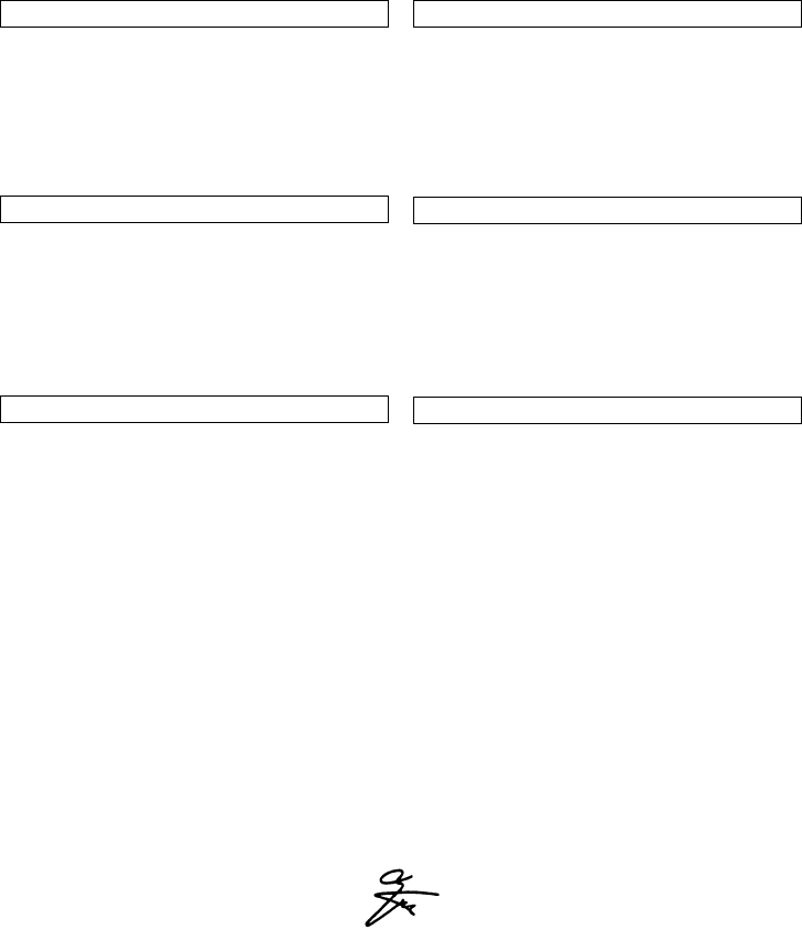
Wanneer de schijf aanzienlijk is versleten, plaatst u een
hard, onontvlambaar afstandsstuk achter het werkstuk
zoals afgebeeld in Fig. 8. Met een versleten schijf krijgt u
de beste resultaten door het middenpunt op de omtrek van
de schijf te gebruiken voor het snijden van het werkstuk.
Voor het schuin snijden van werkstukken die breder zijn
dan 65 mm, dient u een recht stuk hout (afstandsstuk)
dat langer is dan 190 mm en breder dan 45 mm aan de
geleideplaat te bevestigen, zoals aangegeven in Fig. 9.
Bevestig dit afstandsstuk door middel van schroeven die
u door de gaten in de geleideplaat aanbrengt.
De schijf zal langer meegaan wanneer u een afstands-
stuk gebruikt dat een beetje smaller is dan het werkstuk
zoals afgebeeld in Fig.10.
Lange werkstukken dienen aan beide kanten te worden
ondersteund door blokjes onontvlambaar materiaal,
zodat het werkstuk horizontaal op het voetstuk blijft rus-
ten. (Fig. 11)
21
Werking van de schakelaar
LET OP:
Alvorens het gereedschap op een stopcontact aan te
sluiten, dient u altijd te controleren of de trekschakelaar
behoorlijk werkt en bij loslaten naar de “OFF” positie
terugkeert.
Voor gereedschappen met een afsluitknop
(Fig. 12)
Een afsluitknop is voorzien om te voorkomen dat de trek-
schakelaar per toeval wordt ingedrukt. Om het gereed-
schap te starten, druk eerst de afsluitknop in en druk dan
de trekschakelaar in. Om het gereedschap te stoppen,
de trekschakelaar loslaten.
Voor gereedschappen met een vergrendelknop
(Fig. 13)
Om het gereedschap te starten, drukt u gewoon de trek-
schakelaar in. Laat de trekschakelaar los om het gereed-
schap te stoppen. Voor continuë bediening, de
trekkerschakelaar indrukken en vervolgens de vastzet-
knop indrukken. Om het gereedschap vanuit deze ver-
grendelde stand te stoppen, de trekschakelaar helemaal
indrukken en vervolgens loslaten.
Bediening
Houd de handgreep stevig vast. Schakel het gereed-
schap in en wacht tot de schijf op volle toeren draait. Laat
nu de schijf langzaam op het werkstuk zakken. Wanneer
de schijf het werkstuk raakt, oefent u geleidelijk aan meer
druk uit op de handgreep voor het maken van de snede.
Nadat de snede is gemaakt, schakelt u het gereedschap
uit en WACHT TOTDAT DE SCHIJF VOLLEDIG TOT
STILSTAND IS GEKOMEN alvorens de handgreep naar
zijn hoogste positie terug te brengen.
LET OP:
De juiste druk op de handgreep en de maximale snij- effi-
ciëntie kunt u bepalen aan de hand van de hoeveelheid
gemaakte vonken. U dient de druk op de handgreep zo
te regelen dat de maximale hoeveelheid vonken wordt
geproduceerd. Oefen geen overmatige druk uit op de
handgreep, aangezien de snij-efficiëntie hierdoor kan
verminderen en vroegtijdige slijtage van de schijf als-
mede mogelijke beschadiging van het gereedschap, de
schijf of het werkstuk kunnen worden veroorzaakt.
Snijcapaciteit
De maximale snijcapaciteit hangt af van de snijhoek en de vorm van het werkstuk. Toelaatbare diameter van
de schijf: 355 mm
Gereedschapskop-schuifsysteem
Wanneer u aan de handgreep trekt, schuift de gereedschapskop ongeveer 17 mm achterwaarts naar u toe. Dit
systeem is handig voor de volgende toepassingen.
1. Wanneer u dikke pijpen of staven snijdt: (Fig.14)
Beweeg de handgreep heen en weer om de gereedschapskop te doen schuiven. Hierdoor vermeerdert de snij-
efficiëntie en wordt belasting van de schijf voorkomen.
2. Wanneer u sleuven of hoeken snijdt: (Fig.15)
Trek aan de handgreep indien een gedeelte van het werkstuk in uw nabijheid niet is afgesneden. De gereedsc-
hapskop schuift naar achteren en de schijf snijdt het niet afgesneden gedeelte eraf. Indien het niet afgesneden
gedeelte met deze methode niet kan worden afgesneden, gebruik dan een afstandsstuk zoals eerder werd uit-
gelegd.
Voor gereedschap met een onderkap (Fig. 16)
U kunt het stof dat in de onderkap is verzameld als volgt
verwijderen. Plaats het gereedschap ondersteboven, ver-
wijder de vleugelbout en trek de onderkap open zoals
afgebeeld. Sluit de onderkap en zet deze weer goed
vast met de vleugelbout nadat het stof is verwijderd.
Dragen van het gereedschap (Fig. 17)
Vouw de gereedschapskop naar beneden tot u de ketting
kunt vasthaken aan de haak op de handgreep.
ONDERHOUD
LET OP:
Zorg er altijd voor dat het gereedschap is uitgeschakeld
en de stekker uit het stopcontact is verwijderd alvorens
onderhoud aan het gereedschap uit te voeren.
Vervangen van koolborstels (Fig. 18 en 19)
Vervang de borstels wanneer ze tot aan de aangegeven
limiet zijn afgesleten. Beide koolborstels dienen tegelijk-
ertijd te worden vervangen.
Opdat het gereedschap veilig en betrouwbaar blijft,
dienen alle reparaties, onderhoud of afstellingen te
worden uitgevoerd bij een erkend Makita service cen-
trum.
Vor m van
werkstuk
Snijhoek
90° 115 mm 120 mm
115 mm x 142 mm
102 mm x 197 mm
70 mm x 240 mm
139 mm
45° 115 mm 106 mm 115 mm x 102 mm 100 mm
A
A
A x B B
A
A
A
44
ENH003-4
EC-DECLARATION OF CONFORMITY
We declare under our sole responsibility that this product
is in compliance with the following standards of standard-
ized documents,
EN61029, EN55014, EN61000
in accordance with Council Directives, 73/23/EEC,
89/336/EEC and 98/37/EC.
DÉCLARATION DE CONFORMITÉ CE
Nous déclarons sous notre entière responsabilité que ce
produit est conforme aux normes des documents stan-
dardisés suivants,
EN61029, EN55014, EN61000
conformément aux Directives du Conseil, 73/23/CEE,
89/336/CEE et 98/37/EG.
CE-KONFORMITÄTSERKLÄRUNG
Hiermit erklärt wir unter unserer alleinigen Verantwor-
tung, daß dieses Produkt gemäß den Ratsdirektiven 73/
23/EWG, 89/336/EWG und 98/37/EG mit den folgenden
Normen von Normendokumenten übereinstimmen:
EN61029, EN55014, EN61000.
DICHIARAZIONE DI CONFORMITÀ
CON LE NORME DELLA COMUNITÀ EUROPEA
Dichiariamo sotto la nostra sola responsabilità che
questo prodotto è conforme agli standard di documenti
standardizzati seguenti:
EN61029, EN55014, EN61000
secondo le direttive del Consiglio 73/23/CEE, 89/336/CEE e
98/37/CE.
EG-VERKLARING VAN CONFORMITEIT
Wij verklaren hierbij uitsluitend op eigen verant-
woordelijkheid dat dit produkt voldoet aan de volgende
normen van genormaliseerde documenten,
EN61029, EN55014, EN61000
in overeenstemming met de richtlijnen van de Raad 73/
23/EEC, 89/336/EEC en 98/37/EC.
DECLARACIÓN DE CONFORMIDAD DE LA CE
Declaramos bajo nuestra sola responsabilidad que este
producto cumple con las siguientes normas de docu-
mentos normalizados,
EN61029, EN55014, EN61000
de acuerdo con las directivas comunitarias, 73/23/EEC,
89/336/EEC y 98/37/CE.
Yasuhiko Kanzaki
CE 2005
Director Amministratore
Directeur Directeur
Direktor Director
MAKITA INTERNATIONAL EUROPE LTD.
Michigan Drive, Tongwell, Milton Keynes,
Bucks MK15 8JD, ENGLAND
Responsible manufacturer: Produttore responsabile:
Fabricant responsable
:
Verantwoordelijke fabrikant:
Verantwortlicher Hersteller: Fabricante responsable:
Makita Corporation Anjo Aichi Japan
ENGLISH
FRANÇAISE
DEUTSCH
ITALIANO
NEDERLANDS
ESPAÑOL
45
ENH003-4
DECLARAÇÃO DE CONFORMIDADE DA CE
Declaramos sob inteira responsabilidade que este
produto obedece às seguintes normas de documentos
normalizados,
EN61029, EN55014, EN61000
de acordo com as directivas 73/23/CEE, 89/336/CEE e
98/37/CE do Conselho.
EU-DEKLARATION OM KONFORMITET
Vi erklærer hermed på eget ansvar, at dette produkt er i
overensstemmelse med de følgende standarder i de norm-
sættende dokumenter,
EN61029, EN55014, EN61000
i overensstemmelse med Rådets Direktiver 73/23/EEC,
89/336/EEC og 98/37/EC.
EG-DEKLARATION OM ÖVERENSSTÄMMELSE
Under eget ansvar deklarerar vi härmed att denna
produkt överensstämmer med följande standardiseringar
för standardiserade dokument,
EN61029, EN55014, EN61000
i enlighet med EG-direktiven 73/23/EEC, 89/336/EEC
och 98/37/EC.
EUs SAMSVARS-ERKLÆRING
Vi erklærer på eget ansvar at dette produktet er i over-
ensstemmelse med følgende standard i de standardis-
erte dokumenter:
EN61029, EN55014, EN61000,
i samsvar med Råds-direktivene, 73/23/EEC, 89/336/
EEC og 98/37/EC.
VAKUUTUS EC-VASTAAVUUDESTA
Yksinomaisesti vastuullisina ilmoitamme, että tämä tuote
on seuraavien standardoitujen dokumenttien standar-
dien mukainen,
EN61029, EN55014, EN61000
neuvoston direktiivien 73/23/EEC, 89/336/EEC ja 98/37/
EC mukaisesti.
∆ΗΛΩΣΗ ΣΥΜΜΟΡΦΩΣΗΣ ΕΚ
∆ηλώνουµε υπ την µοναδική µας ευθύνη τι αυτ
το προιν βρίσκεται σε Συµφωνία µε τα ακλουθα
πρτυπα τυποποιηµένων εγγράφων,
EN61029, EN55014, EN61000
σύµφωνα µε τις Οδηγίες του Συµβουλίου, 73/23/
EEC, 89/336/EEC και 98/37/ΚE.
Yasuhiko Kanzaki
CE 2005
Director Direktor
DirektørJohtaja
Direktör ∆ιευθυντής
MAKITA INTERNATIONAL EUROPE LTD.
Michigan Drive, Tongwell, Milton Keynes,
Bucks MK15 8JD, ENGLAND
Fabricante responsável: Ansvarlig produsent:
Ansvarlig fabrikant: Vastaava valmistaja:
Ansvarig tillverkare: Υπεύθυνος κατασκευαστής:
Makita Corporation Anjo Aichi Japan
PORTUGUÊS
DANSK
SVENSKA
NORSK
SUOMI
ΕΛΛΗΝΙΚΑ
46
Noise and Vibration
The typical A-weighted noise levels are
sound pressure level: 97 dB (A)
sound power level: 110 dB (A)
Wear ear protection.
The typical weighted root mean square acceleration value is
not more than 2.5 m/s
2
.
Bruit et vibrations
Les niveaux de bruit pondérés A types sont:
niveau de pression sonore: 97 dB (A)
niveau de puissance du son: 110dB (A)
Porter des protecteurs anti-bruit.
Laccélération pondérée ne dépasse pas 2,5 m/s
2
.
Geräusch- und Vibrationsentwicklung des Modells
Die typischen A-bewerteten Geräuschpegel betragen:
Schalldruckpegel: 97 dB (A)
Schalleistungspegel: 110 dB (A)
Gehörschutz tragen.
Der gewichtete Effektivwert der Beschleunigung beträgt nicht
mehr als 2,5m/s
2
.
Rumore e vibrazione
I livelli del rumore pesati secondo la curva A sono:
Livello pressione sonora: 97 dB (A)
Livello potenza sonora: 110 dB (A)
Indossare i paraorecchi.
Il valore quadratico medio di accellerazione non supera i
2,5m/s
2
.
Geluidsniveau en trilling
De typische A-gewogen geluidsniveaus zijn
geluidsdrukniveau: 97dB (A)
geluidsenergie-niveau: 110 dB (A)
Draag oorbeschermers.
De typische gewogen effectieve versnellingswaarde is niet
meer dan 2,5m/s
2
.
Ruido y vibración
Los niveles típicos de ruido ponderados A son
presión sonora: 97 dB (A)
nivel de potencia sonora: 110dB (A)
Póngase protectores en los oídos.
El valor ponderado de la aceleración no sobrepasa los 2,5m/s
2
.
Ruído e vibração
Os níveis normais de ruído A são
nível de pressão de som: 97 dB (A)
nível do sum: 110dB (A)
Utilize protectores para os ouvidos
O valor médio da aceleração é inferior a 2,5 m/s
2
.
Lyd og vibration
De typiske A-vægtede lydniveauer er
lydtryksniveau: 97dB (A)
lydeffektniveau: 110 dB (A)
Bær høreværn.
Den vægtede effektive accelerationsværdi overstiger ikke
2,5 m/s
2
.
Buller och vibration
De typiska A-vägda bullernivåerna är
ljudtrycksnivå 97dB (A)
ljudeffektnivå: 110 dB (A)
Använd hörselskydd
Det typiskt vägda effektivvärdet för acceleration överstiger
inte 2,5 m/s
2
.
Støy og vibrasjon
De vanlige A-belastede støynivå er
lydtrykksnivå:97dB (A)
lydstyrkenivå: 110 dB (A)
Benytt hørselvern.
Den vanlig belastede effektiv-verdi for akselerasjon over-
skrider ikke 2,5 m/s
2
.
Melutaso ja tärinä
Tyypilliset A-painotetut melutasot ovat
äänenpainetaso: 97dB (A)
äänen tehotaso: 110 dB (A)
Käytä kuulosuojaimia.
Tyypillinen kiihtyvyyden painotettu tehollisarvo ei ylitä 2,5 m/s
2
.
Θρυβος και κραδασµς
Οι τυπικές A-µετρούµενες εντάσεις ήχου είναι
πίεση ήχου 97 dB (A)
δύναµη του ήχου:
110 dB (A)
– Φοράτε ωτοασπίδες.
Η τυπική αξία της µετρούµενης ρίζας του µέσου
τετραγώνου της επιτάχυνσης δεν ξεπερνά τα 2,5 m/s
2
.
ENGLISH
FRANÇAISE
DEUTSCH
ITALIANO
NEDERLANDS
ESPOL
PORTUGUÊS
DANSK
SVENSKA
NORSK
SUOMI
ΕΛΛΗΝΙΚΑ
47
M
Makita Corporation
Anjo, Aichi, Japan
883859E945
1

Hulp nodig? Stel uw vraag in het forum

Spelregels

Misbruik melden

Gebruikershandleiding.com neemt misbruik van zijn services uitermate serieus. U kunt hieronder aangeven waarom deze vraag ongepast is. Wij controleren de vraag en zonodig wordt deze verwijderd.

Product:

Bijvoorbeeld antisemitische inhoud, racistische inhoud, of materiaal dat gewelddadige fysieke handelingen tot gevolg kan hebben.

Bijvoorbeeld een creditcardnummer, een persoonlijk identificatienummer, of een geheim adres. E-mailadressen en volledige namen worden niet als privégegevens beschouwd.

Spelregels forum

Om tot zinvolle vragen te komen hanteren wij de volgende spelregels:

Belangrijk! Als er een antwoord wordt gegeven op uw vraag, dan is het voor de gever van het antwoord nuttig om te weten als u er wel (of niet) mee geholpen bent! Wij vragen u dus ook te reageren op een antwoord.

Belangrijk! Antwoorden worden ook per e-mail naar abonnees gestuurd. Laat uw emailadres achter op deze site, zodat u op de hoogte blijft. U krijgt dan ook andere vragen en antwoorden te zien.

Abonneren

Abonneer u voor het ontvangen van emails voor uw Makita 2414 bij:


U ontvangt een email met instructies om u voor één of beide opties in te schrijven.


Ontvang uw handleiding per email

Vul uw emailadres in en ontvang de handleiding van Makita 2414 in de taal/talen: Nederlands, Duits, Engels, Frans, Italiaans, Portugees, Spaans, Deens, Zweeds, Noors, Fins als bijlage per email.

De handleiding is 0,25 mb groot.


U ontvangt de handleiding per email binnen enkele minuten. Als u geen email heeft ontvangen, dan heeft u waarschijnlijk een verkeerd emailadres ingevuld of is uw mailbox te vol. Daarnaast kan het zijn dat uw internetprovider een maximum heeft aan de grootte per email. Omdat hier een handleiding wordt meegestuurd, kan het voorkomen dat de email groter is dan toegestaan bij uw provider.

Stel vragen via chat aan uw handleiding

Stel uw vraag over deze PDF

Uw handleiding is per email verstuurd. Controleer uw email

Als u niet binnen een kwartier uw email met handleiding ontvangen heeft, kan het zijn dat u een verkeerd emailadres heeft ingevuld of dat uw emailprovider een maximum grootte per email heeft ingesteld die kleiner is dan de grootte van de handleiding.

Er is een email naar u verstuurd om uw inschrijving definitief te maken.

Controleer uw email en volg de aanwijzingen op om uw inschrijving definitief te maken

U heeft geen emailadres opgegeven

Als u de handleiding per email wilt ontvangen, vul dan een geldig emailadres in.

Uw vraag is op deze pagina toegevoegd

Wilt u een email ontvangen bij een antwoord en/of nieuwe vragen? Vul dan hier uw emailadres in.


Info