Chère cliente, Cher client,
merci et sincères félici-
tations pour le choix que
vous avez fait.
Ce nouveau produit,
développé avec soin et
fabriqué avec des matières
de toute première qualité,
a été soigneusement rodé
pour satisfaire toutes Vos
exigences d’une cuisson
parfaite.
Veuillez lire attentivement
les instructions simples
portées sur cette notice qui
vous permettront d’obte-
nir d’excellents résultats
dès la première utilisation.
Nous vous souhaitons une
entière et pleine satisfac-
tion quant à l’utilisation
de cet appareil moderne.
LE CONSTRUCTEUR
TABLES DE CUISSON
Installation - Emploi - Entretien
Notice
d’emploi
Installation
Toutes les opérations rela-
tives à l’installation
(branchement électrique,
raccordement gaz,
adaptation au type de gaz,
réglages nécessaires, etc...)
doivent être effectuées par
des spécialistes suivant les
normes en vigueur.
Pour les instructions spéci-
fiques, voir la partie qui
concerne les modalités
d’installation.
Mode d’emploi
Brûleurs à gaz (Fig. 1-3). On
allume le brûleur en ap-
prochant une petite flamme
aux trous de sa partie
supérieure en poussant et
tournant dans le sens
contraire des aiguilles d’une
montre la manette corre-
spondant jusqu’à faire coïn-
cider l’aiguille avec la
position de maximum.
Quand le bruleur est en
marche, règler la flamme
selon la nécéssité. La po-
sition de minimum se
trouve à la fin de la rotation
contraire au sens des aiguil-
les d’une montre.
Pour les modèles à allu-
mage automatique tourner
la manette comme indiquè
ci-dessus, en poussant en
meme temps le bouton
spècial. Pour les modèles à
allumage automatique/
simultané (à une main), il
suffit d’agir sur le bouton
correspondant, comme il est
indiqué ci-dessus. La dé-
charge électrique entre la
petite bougie et le brûleur
allume le brûleur interessé.
Quand le brûleur est
allumé, lâcher la manette, et
regler la flamme selon
nécéssité.
Dans le cas de modèles
doués de sûreté thermo-
T70.?=4<@07,77@8,20/@
-=]70@=,740@.:880/,9>
70>.,>/T.=4?>.4/0>>@>09
,;;@D,9?N1:9/>@=7,
8,90??0;7,.T0N7,;:>4?4:9
8,C48,70;09/,9?09A4=:9
>0.:9/0>@8:809?
:[A:@>=07P.30E7,8,90??0
,>>@=0EA:@><@070-=]70@=
0>?,77@8T
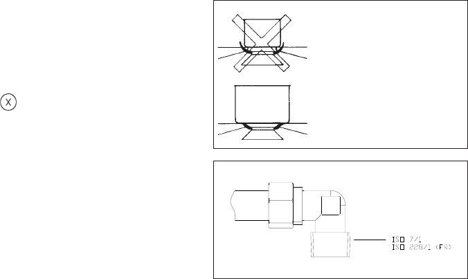
":9*:@>.:9>04770
/I@?474>0=/0>.,>>0=:70>
,A0.@9/4,8S?=0;=:;:=
?4:99T,@C-=]70@=>TA4?,9?
<@07,17,880,@8,C48@8
/T-:=/0/070@=1:9/
907,4>>0E5,8,4>/0.,>
>0=:70>A4/0>>@=7010@,7
7@8T
908;7:D0E;,>/@>?09
>470>;:@=.@4>>:92=477>@=
70>;7,<@0>/0>>@>A0==0
7,149/07,.@4>>:9471,@?
10=80=70=:-490?;=49.4;,7
/@.:9/@4?0?:@/07,-:@
?04770
Important
a) sur les plaques dotées de sécurité
thermoélectrique, ne pas activer
l’allumage pendant plus de 15
secondes. Si , après 15 secondes le
brûleur ne s’est pas allumé, ouvrir
la porte de la pièce et attendre
au moins une minute avant de
réessayer.
b) sur les plaques qui ne sont
pas dotées de sécurité, en
cas d’extinction des flammes
d’un brûleur, fermer le robinet
correspondant et attendre au moins
une minute avant de réessayer.
Entretien
Avant de toute opèration,
débrancher l’appareil du
reseau électrique. Pour
assurer une longue vie á
l’appareil il faut
absolument effectuer de
temps en temps un net-
toyage général soigneux
en gardant à l’esprit ce qui
suit:
• les parties en vitre, acier
et/ou émaillées doivent
etre nettoyées avec des
produits appropriés
(faciles à trouver ans les
magasins) non abrasifs
ni corrosifs. Eviter les
produits qui contien-
nent du chlore (eau de
Javel.etc,)
• éviter de laisser sur la
table de travail des sub-
stances acides ou al-
calines (vinaigre, sel, jus
de citron, etc.)
• les orifices du bruleûr et
les chapeaux (pièces
mobiles du bruleur)
doivent etre frequem-
ment lavés avec de
l’eau bouillante et du
détergent, en ayant soin
d’enlever tout incru-
station, ensuite ils
doivent etre essuyés
soigneusement, en con-
trolant que tous les
trous soient débouchés.
• les plaques électriques
doivent être nettoyées
avec un torchon humi-
de et un peu huilées
quand elles sont encore
tièdes.
• les grilles inox du plan
de travail après avoir
été chauffées prennent
une couleur bleuâtre
qui ne deterieoure pas
leur qualité. Pour leur
rendre leur aspect origi-
nal employer un pro-
duit un peu abrasif.
N.B.: - Le graissage even-
tuel des robinets doit etre
faite par des spécialités,
qui doivent etre appelés
en cas d’anomalie de fon-
ctionnement. Controler de
temps en temps l’état de
conservation du conduit
flexible d’alimentation
gaz. Si il y a des fuites
remplacer
immediatement. Dans
tous les cas ne pas oublier
de la changer avant la
date limite indiquée sur le
tube.
FR
POUR USAGE DOMESTIQUE.
OU ABSURDE.