LITTLE TIKES® is a trademark of Little Tikes in the U.S. and
other countries. All logos, names, characters, likenesses,
images, slogans, and packaging appearance are the property
of Little Tikes.
Printed in U.S.A. · 0621-2-E
Little Tikes Consumer Service
2180 Barlow Road
Hudson, Ohio 44236 U.S.A.
1-800-321-0183
Please keep this manual as it contains important information.
THIS PRODUCT IS INTENDED FOR USE BY CHILDREN FROM AGES 3 TO 10.
CAPACITY: 6 USERS MAXIMUM - WEIGHT LIMIT: 110 lbs. (50 kg) PER CHILD
PANTHER PEAK
At minimum, two people are required
to lift the boxes that contain the parts
for this unit and to assemble this unit.
72
2
1. Have your receipt handy.
2. Locate the item number on the front of this manual.
3. Reference the parts list in this manual.
If any parts are damaged or missing, please contact
consumer service before returning the item.
LITTLE TIKES®
1-800-321-0183
• To reduce the risk of serious injury or death, you MUST read and follow these instructions before assembly and before use. Pay close attention to the
important information, warnings and safety information. Keep and refer to these instructions often. Give them to any future owner of this unit.
• The boxes containing the parts for this unit are very heavy. Do not attempt to lift by yourself. To prevent possible injury, at least two people are required to
lift these boxes.
• After reviewing the entire manual, decide if you will need professional assistance assembling this unit.
• Before beginning assembly, separate and identify the contents of this unit to ensure you have all parts listed in this manual.
• If you cannot nd a part, check the packing materials thoroughly, as loose parts and small pieces may have shifted in transit.
• If any part is missing or damaged, contact Little Tikes Consumer Service: www.littletikes.com or 1-800-321-0183.
READ THIS ENTIRE MANUAL THOROUGHLY BEFORE ASSEMBLY AND USE.
Please retain these instructions for future reference, and take a moment to write down this information for ecient service.
It is recommended you attach your dated sales
receipt to this page for future reference.
ITEM NUMBER:
PURCHASE LOCATION:
DATE OF PURCHASE:
INSTALLATION DATE:
INSTALLED BY:
8 a.m. - 8 p.m. EST 7 DAYS A WEEK
71
3
• To reduce the risk of serious injury or death, you MUST read and
follow these instructions before assembly and before use.
• CONTINUOUS ADULT SUPERVISION IS REQUIRED.
• This unit is recommended for use by children 3-10 years of age.
• WARNING: ONLY FOR DOMESTIC USE.
• RESIDENTIAL HOME USE ONLY. This unit is not intended for public use.
The manufacturer does not warranty this product if it is used for
commercial purposes like daycare, schools, churches, nurseries or parks.
• Children must not use this product prior to complete assembly and
inspection by a competent adult. The unit must be fully assembled,
properly installed and anchored prior to use.
Installation over concrete, asphalt, dirt, grass, carpet and other hard
surfaces creates a risk of serious injury or death from falls to the ground.
Install and maintain shock absorbing material under and around this unit
as recommended in this manual.
Place this unit on level ground at least 6 ft. (2m) from any obstruction
such as a garage or house, fences, poles, trees, sidewalks, walls, landscape
ADULT ASSEMBLY REQUIRED. This product contains small parts and parts
with sharp edges and points. Keep parts away from children until fully
assembled.
Choose a level surface for this equipment. This can reduce the likelihood
of the unit tipping over and loose-ll materials from washing away
during heavy rains. Stakes must be installed straight up and not at an
angle. Ensure soil conditions are adequate to rmly hold the stakes.
DO NOT allow children to play on this unit until assembly is complete and
the unit is properly anchored.
Owners are responsible for maintaining legibility of the warning labels.
Please remove the protective lm on the signage and logo plate before use.
• User safety is our top concern. Read and understand the following statements
and warnings to reduce the likelihood of serious or fatal injury. Review this
information with your child and any other users.
1. ON-SITE, CONTINUOUS ADULT SUPERVISION IS REQUIRED FOR CHILDREN OF ALL
AGES. Most serious injuries and deaths on playground equipment result when
children are playing unsupervised. This product meets all applicable safety
standards. Complying with all warnings and important information in this
manual will reduce the risk of serious or fatal injury to children playing on this
unit. Review all warnings and play information regularly with any child using this
unit. Ensure children fully understand and follow these instructions.
2. This unit is designed for a specic number of users whose combined weight
should not exceed the capacity limitations of 110 lbs. per child with a maximum
of 6 children.
3. DO NOT walk close to, in front of, behind, or between moving swings or other
moving equipment.
4. DO NOT stand on swings. Only sitting is permitted.
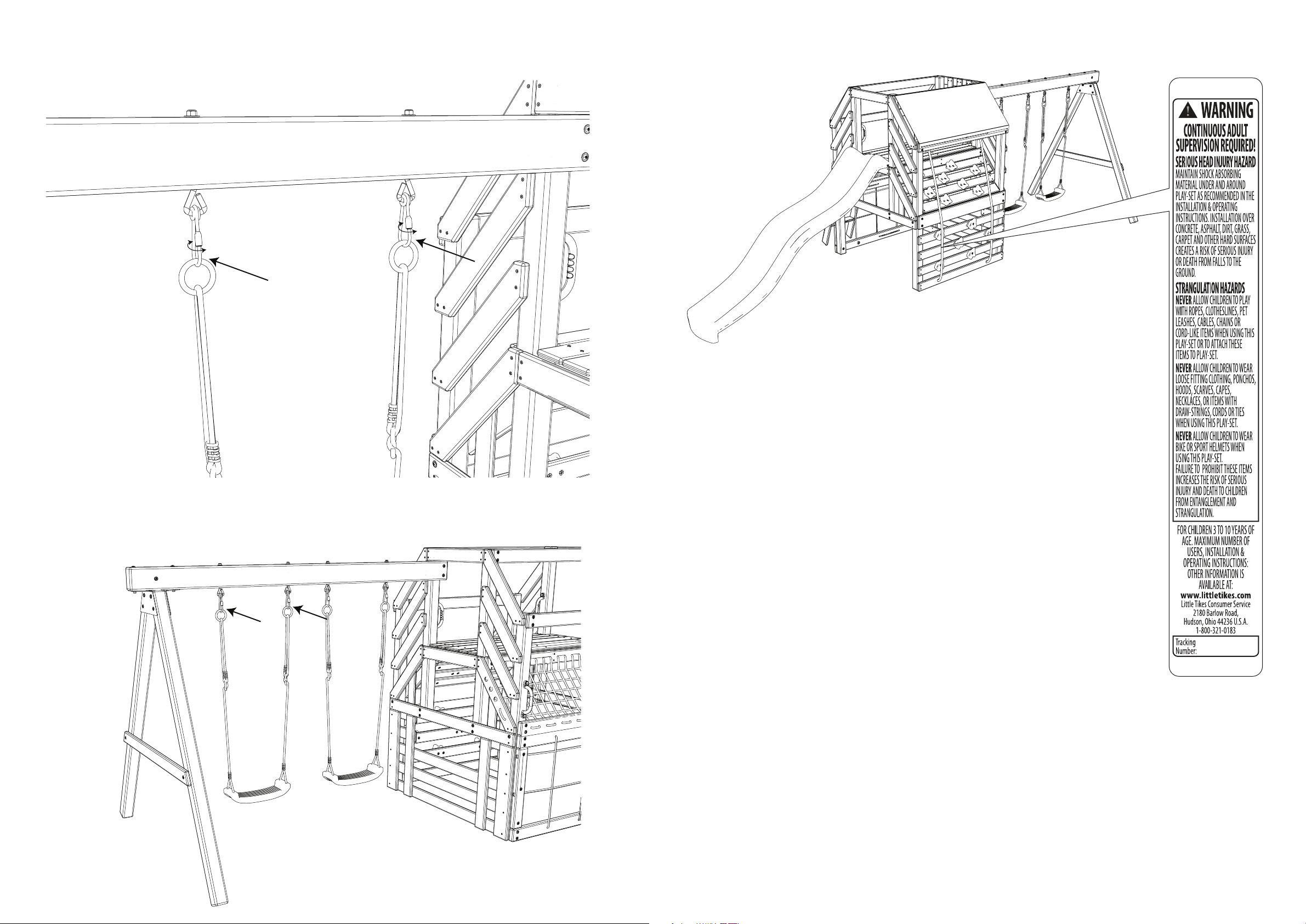
5. DO NOT twist the chains and ropes of the swings or loop them over the top
support bar, as this may reduce the strength of the chain or rope.
6. DO NOT get o swings or other playground equipment in motion.
7. DO NOT push empty swing seats to prevent them from swinging back and causing
possible injury.
8. Children should sit with full weight in the center of the swings to prevent erratic
swing motions and falling o the swings.
9. DO NOT allow children to use the equipment in a manner other than intended.
10. DO NOT slide head rst. Always go down the slide feet rst.
11. Look before sliding to ensure no one is at the bottom of the slide.
12. Never run up a slide, as this increases the chance of falling.
13. DO NOT climb or use the unit when it is wet. Wipe dry before use.
14. DO NOT jump from the deck or any part of the unit. Always use ladders and
ramps. Standing on or jumping from elevated surfaces can be dangerous.
15. DO NOT crawl or climb on the roof.
16. Verify that any suspended climbing rope, chain, or cable is secured at both ends
and that it cannot be looped back on itself and create an entanglement hazard.
17. MINIMUM CLEARANCE BETWEEN SWINGS AND GROUND: 14 in. (350 mm).
18. DO NOT attach items to the unit that are not specically designed for use with
the unit, such as, but not limited to: jump ropes, clotheslines, pet leashes, cables
and chains, as they may cause a strangulation hazard.
19. Any modications made to this product must be carried out according to these
instructions. Installation of included ropes, nets and other attached accessories
must be xed on all ends according to these instructions.
20. Never add extra length to chain or rope. The chains or ropes provided are the
maximum length designed for the swinging elements.
21. DO NOT wrap legs around the swing chain.
22. DO NOT slide down the swing chain.
23. On hot days, check the slide and other plastic components to ensure they are not
too hot for use. Cool the hot slide and any plastic rides with water and wipe dry
before use.
INSTRUCTIONS FOR SAFE USE
IMPORTANT SAFETY INFORMATION
WARNING:
WARNING:
SERIOUS HEAD INJURY HAZARD:
COLLISION HAZARD:
CHOKING HAZARD/ SHARP EDGES & POINTS:
WARNING LABEL:
STRANGULATION HAZARD:
TIP OVER HAZARD:
• NEVER allow children to play with ropes, clotheslines, pet leashes, cables,
chains, cord-like items, or items with a cord or strap when playing on this
unit. DO NOT attach these items or similar items to this unit.
• NEVER allow children to wear loose-tting clothing, such as, but not
limited to: ponchos, hoods, scarves, capes, necklaces, items with
draw-strings, cords or ties when playing on this unit.
Open-toe/open-heel footwear is not permitted. Children should wear
well-tting clothing and closed-toe shoes.
• NEVER allow children to wear bike or sports helmets when playing on this
unit. Instruct them to remove these items before playing on this unit.
70
Step 119:
Congratulations, this completes the assembly of the Panther Peak.
4
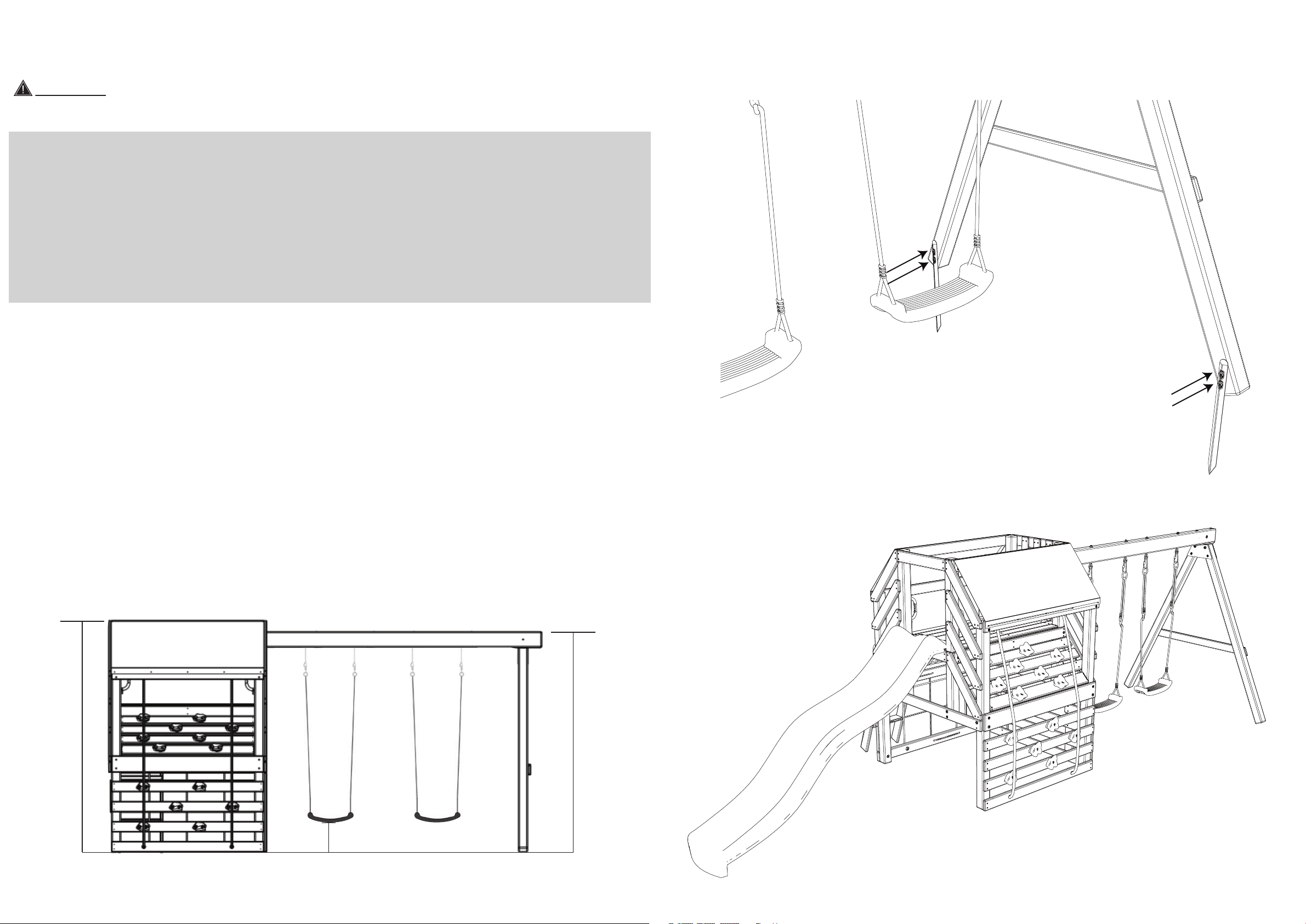
VERTICAL HEIGHT
To reduce the likelihood of serious head injuries, install shock-absorbing protective surfacing under and around this unit. The protective surfacing should be
applied to a depth suitable for the unit height in accordance with ASTM F1292. Follow the guidelines below for each type of surfacing:
• DO NOT install this unit over concrete, asphalt, packed earth, grass,
carpet, or any other hard surface. A fall onto a hard surface can result in
serious injury to the user. Grass and dirt are not considered protective
surfacing because wear and environmental factors can reduce their
shock-absorbing eectiveness. Carpeting and thin mats are not
adequate protective surfacing.
*Ground level equipment, such as a sandbox, activity wall, playhouse or
other equipment that has no elevated play surface, does not need any
protective surfacing.
• PLEASE REFER TO CRITICAL FALL HEIGHT INFORMATION.
• This unit should be installed on a level surface by an ADULT with an
ADULT ASSISTANT. Place the unit on a at area to minimize ground
preparation.
• Choose a level location for this unit to reduce the likelihood of the play
set tipping over and loose-ll surfacing material washing away during
heavy rains.
• Place this unit no less than 6 feet (2 meters) from any structure or
obstruction, such as a fence, garage, house, overhang, branches,
laundry lines, or electrical wires.
• Provide enough room so that children may play on this unit safely. For
example, for structures with multiple play activities, a slide should not
exit in front of a swing.
• Place this unit where adults are easily able to watch children at play.
UNIT POSITIONING
RECOMMENDED SURFACING
IMPORTANT SAFETY INFORMATION
NOTE:
• DO NOT install loose ll surfacing over hard surfaces like concrete or
asphalt.
• Shredded bark mulch, wood chips, ne sand and ne gravel are added as
shock-absorbing materials after assembly. If used properly, these materials
can absorb some of the impact of a child’s fall.
• All surface material should extend a minimum of 6 ft. (2m) in all
directions around the play area.
• DO NOT apply surfacing materials until after the unit is completely
assembled and anchored.
• Create a play area free of obstacles that could cause injuries - such as
low-hanging tree branches, overhead wires, tree stumps or roots, large
rocks, bricks, and concrete.
• Do not build this unit on top of surfacing material.
• Locate bare metal platforms and slides out of direct sunlight to reduct the
likelihood of serious burns.
TIP: A slide that faces north will receive the least direct sunlight.
• Separate active and quiet activities from each other. For example, place
sandboxes away from swings, or use a separation guardrail or barrier.
• For to-fro swings, extend protective surfacing in front of and behind the
swing to a distance equal to twice the height of the top of the bar from
which the swing is suspended.
WARNING:
5’ 11” (1.8m)
6’1” (1.9m)
Minimum
14” (350mm)
69
Step 117:
Hammer (2) Ground Stakes (PC-HD23) into the ground next to the Beam Support Braces as shown.
Secure the Ground Stakes to the Beam Support Braces using (4) Screws (S119).
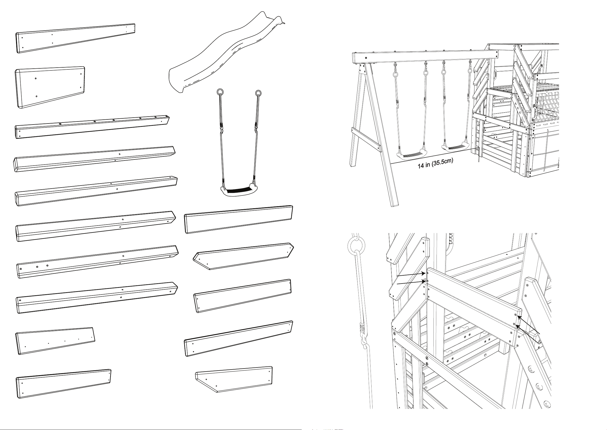
Step 118:
One week later check the Rope length on the Swings to make sure they are 14in (350mm) above the
ground. Make any necessary adjustments. Also, tighten all the hardware.
5
• User safety is our top concern. Read and understand the following statements
and warnings to reduce the likelihood of serious or fatal injury. Review this
information with your child and any other users.
1. ON-SITE, CONTINUOUS ADULT SUPERVISION IS REQUIRED FOR CHILDREN OF ALL
AGES. Most serious injuries and deaths on playground equipment result when
children are playing unsupervised. This product meets all applicable safety
standards. Complying with all warnings and important information in this
manual will reduce the risk of serious or fatal injury to children playing on this
unit. Review all warnings and play information regularly with any child using this
unit. Ensure children fully understand and follow these instructions.
2. This unit is designed for a specic number of users whose combined weight
should not exceed the capacity limitations of 110 lbs. per child with a maximum
of 6 children.
3. DO NOT walk close to, in front of, behind, or between moving swings or other
moving equipment.
4. DO NOT stand on swings. Only sitting is permitted.
5. DO NOT twist the chains and ropes of the swings or loop them over the top
support bar, as this may reduce the strength of the chain or rope.
6. DO NOT get o swings or other playground equipment in motion.
7. DO NOT push empty swing seats to prevent them from swinging back and causing
possible injury.
8. Children should sit with full weight in the center of the swings to prevent erratic
swing motions and falling o the swings.
9. DO NOT allow children to use the equipment in a manner other than intended.
10. DO NOT slide head rst. Always go down the slide feet rst.
11. Look before sliding to ensure no one is at the bottom of the slide.
12. Never run up a slide, as this increases the chance of falling.
13. DO NOT climb or use the unit when it is wet. Wipe dry before use.
14. DO NOT jump from the deck or any part of the unit. Always use ladders and
ramps. Standing on or jumping from elevated surfaces can be dangerous.
15. DO NOT crawl or climb on the roof.
16. Verify that any suspended climbing rope, chain, or cable is secured at both ends
and that it cannot be looped back on itself and create an entanglement hazard.
17. MINIMUM CLEARANCE BETWEEN SWINGS AND GROUND: 14 in. (350 mm).
18. DO NOT attach items to the unit that are not specically designed for use with
the unit, such as, but not limited to: jump ropes, clotheslines, pet leashes, cables
and chains, as they may cause a strangulation hazard.
19. Any modications made to this product must be carried out according to these
instructions. Installation of included ropes, nets and other attached accessories
must be xed on all ends according to these instructions.
20. Never add extra length to chain or rope. The chains or ropes provided are the
maximum length designed for the swinging elements.
21. DO NOT wrap legs around the swing chain.
22. DO NOT slide down the swing chain.
23. On hot days, check the slide and other plastic components to ensure they are not
too hot for use. Cool the hot slide and any plastic rides with water and wipe dry
before use.
SAFETY SURFACING REQUIREMENTS
CRITICAL FALL HEIGHT
Material
Wood Chips
6” (152mm)
7’ (2.13m)10’ (3.05m)11’ (3.35m)10’ (3.05m)
6’ (2m)10’ (3.05m)11’ (3.35m)7’ (2.13m)
6’ (2m)7’ (2.13m)> 12’ (3.66m)6’ (2m)
5’ (1.52m)5’ (1.52m)9’ (2.74m)5’ (1.52m)
5’ (1.52m)5’ (1.52m)6’ (2m)4’ (1.22m)
5’ (1.52m)7’ (2.13m)10’ (3.05m)6’ (2m)
5’ (1.52m)5’ (1.52m)6’ (2m)5’ (1.52m)
10-12’ (3.0-3.6m)N/AN/AN/A
9” (228mm)12” (304mm)to 9” (228mm)
Double-Shredded Bark Mulch
Engineered Wood Fibers (EWF)
Fine Sand
Coarse Sand
Fine Gravel
Medium Gravel
Shredded Tires*
Uncompressed DepthCompressed Depth
IMPORTANT SAFETY INFORMATION
* This data is from tests conducted by independent testing laboratories on a 6-inch depth of uncompressed shredded tire samples produced by four
manufacturers. The tests reported critical heights, which varied from 10 feet to greater than 12 feet. It is recommended that persons seeking to install
shredded tires as a protective surface request test data from the supplier showing the critical height of the material when it was tested in accordance with
ASTM F1292.
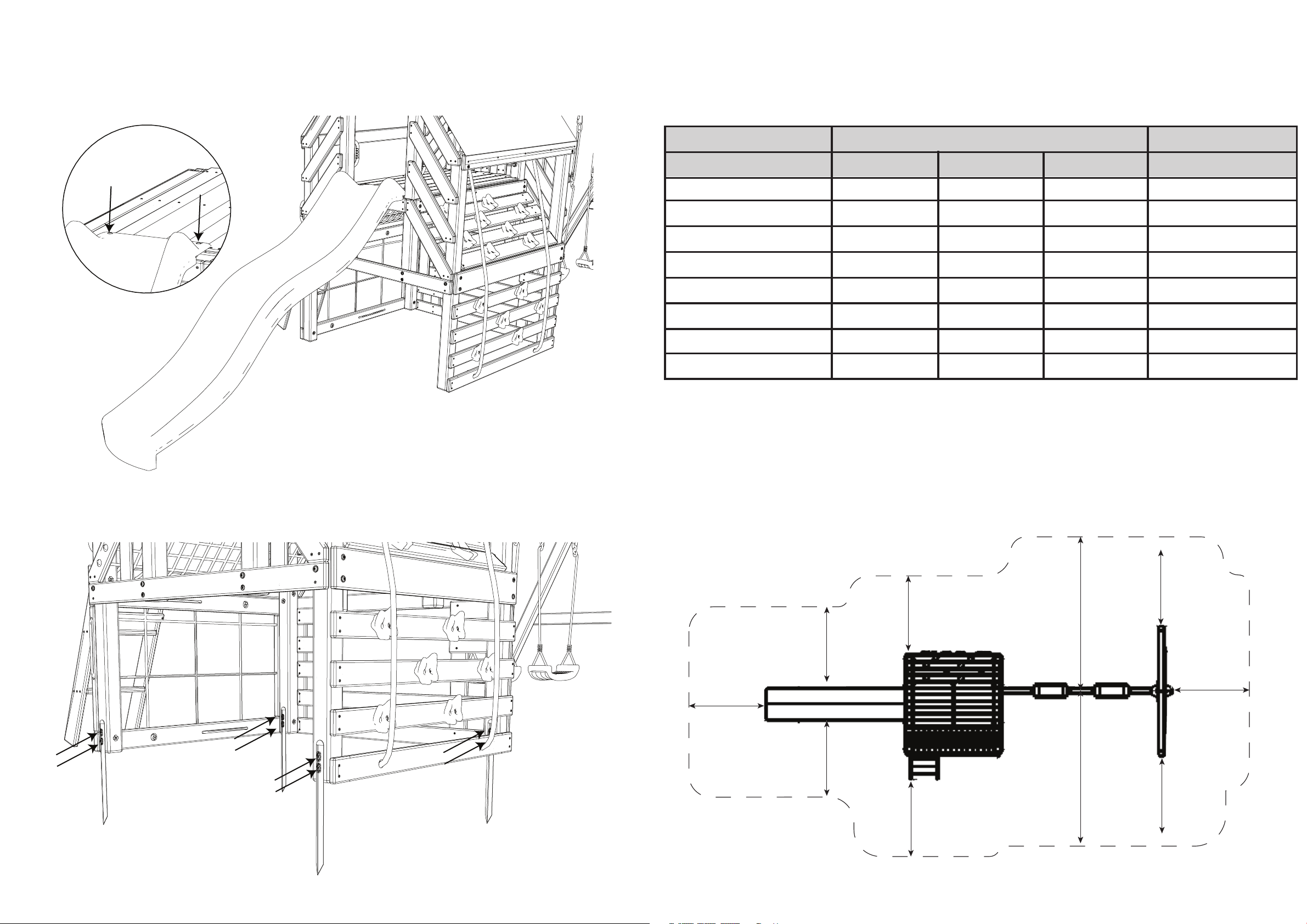
Maximum critical fall height is 6 feet (2m). The obstacle-free safety zone which requires safety surfacing is a perimeter that extends 6 feet (2 meters)
out from the unit and at least 12 feet (3.7 meters) in front and back of to-fro swings.
6’ (2M)
6’ (2M)
6’ (2M)
6’ (2M)
6’ (2M)
6’ (2M)
6’ (2M)
6’ (2M)
12’ (3.7M)
12’ (3.7M)
68
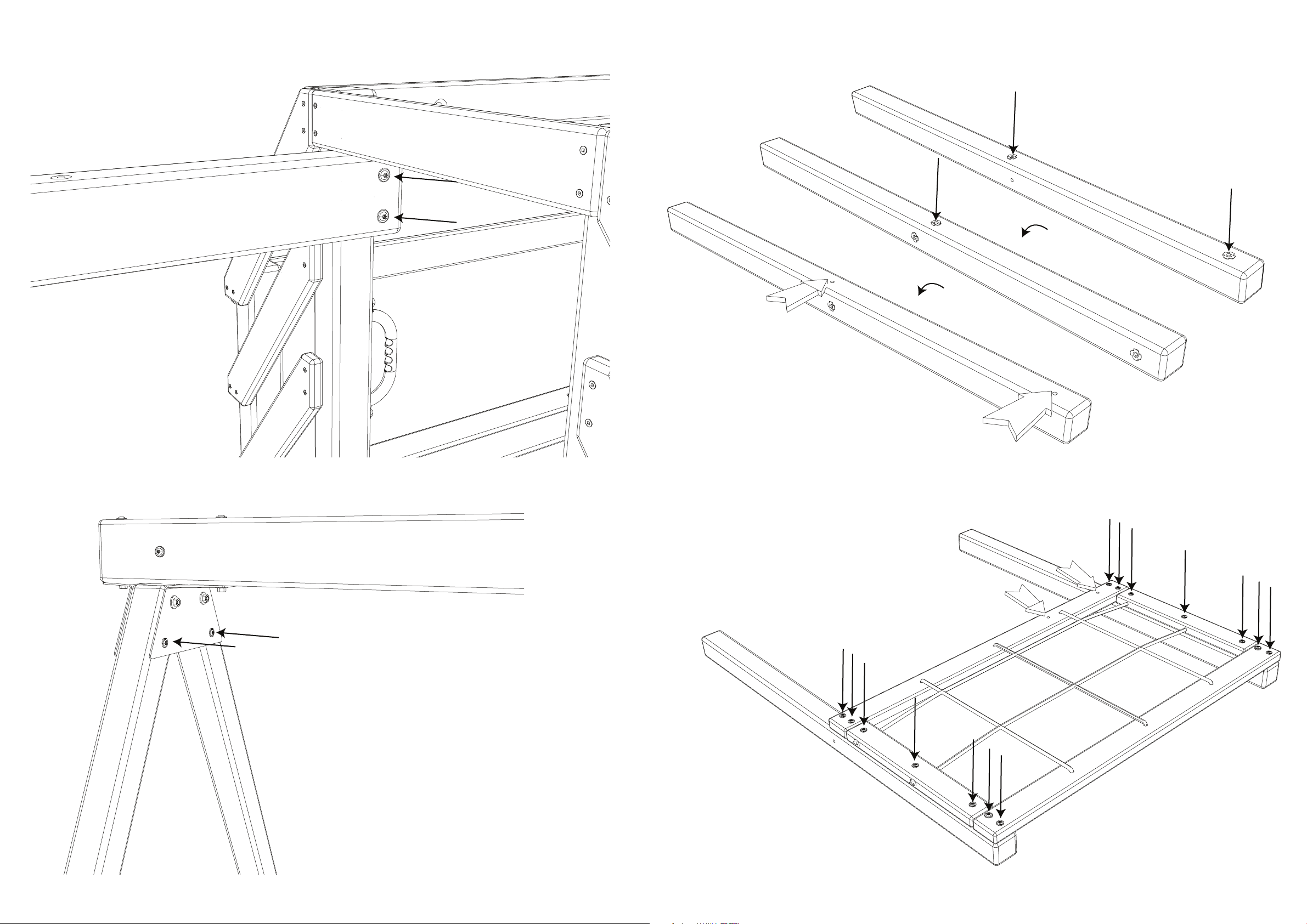
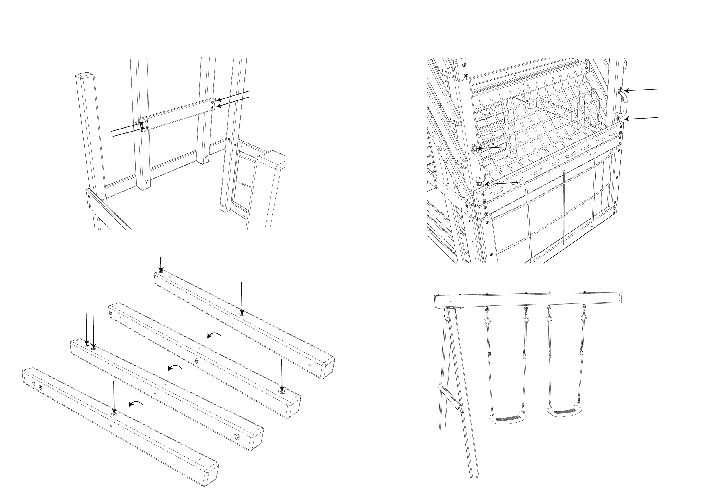
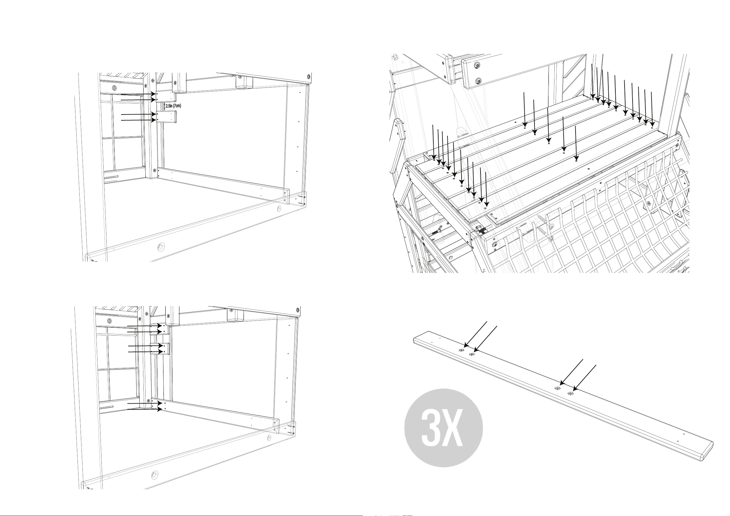
Step 115:
Attach the Slide (PC-SL02) to Floor Support (018) using (2) Screws (S79). Ensure the Screws pass through
the Floorboards and are secured in the Floor Support (018).
WARNING: Do not lift the Slide up or pull the Slide aside after assembling.
Step 116:
Hammer (4) Ground Stakes (PC-HD23) into the ground next to the Tower Legs as shown. Secure the
Ground Stakes to the Tower Legs using (8) Screws (S119).
6
INFORMATION ON PLAYGROUND SURFACING MATERIALS
The following information is from the United States Consumer Product Safety Commission’s Information
Sheet for playground surfacing material. Additional Information can be found here:
https://www.cpsc.gov/s3fs-public/324.pdf
SECTION 4 OF THE CONSUMER PRODUCT SAFETY COMMISSION’S OUTDOOR HOME PLAYGROUND SAFETY HANDBOOK
Select Protective Surfacing
One of the most important things you can do to reduce the likelihood of serious head injuries is to install shock-absorbing protective surfacing
under and around your play equipment. The protective surfacing should be applied to a depth that is suitable for the equipment height in accordance with
ASTM F 1292. There are dierent types of surfacing to choose from; whichever product you select, follow these guidelines:
NOTE: Do not install home playground equipment over concrete, asphalt, or any other hard surface. A fall onto a hard surface can result in serious
injury to the equipment user. Grass and dirt are not considered protective surfacing because wear and environmental factors can reduce their shock
absorbing eectiveness. Carpeting and thin mats are generally not adequate protective surfacing. Ground level equipment such as a sandbox,
activity wall, playhouse or other equipment that has no elevated play surface – does not need any protective surfacing.
Loose-Fill Materials:
• Maintain a minimum depth of 9 inches of loose-ll materials such as wood mulch/chips, engineered wood ber (EWF), or
shredded/recycled rubber mulch for equipment up to 8 feet high; and 9 inches of sand or pea gravel for equipment up to 5 feet high.
NOTE: An initial ll level of 12 inches will compress to about a 9-inch depth of surfacing overtime. The surfacing will also compact,
displace, and settle, and should be periodically relled to maintain at least a 9-inch depth.
• Use a minimum of 6 inches of protective surfacing for play equipment less than 4 feet in height. If maintained properly, this should be
adequate. (At depths less than 6 inches, the protective material is too easily displaced or compacted.)
• Use containment, such as digging out around the perimeter and/or lining the perimeter with landscape edging. Don’t forget to
account for water drainage.
• Check and maintain the depth of the loose-ll surfacing material. To maintain the right amount of loose-ll materials, mark the correct
level on play equipment support posts. That way you can easily see when to replenish and/or redistribute the surfacing.
• Do not install loose-ll surfacing over hard surfaces such as concrete or asphalt.
Poured-In-Place Surfaces or Pre-Manufactured Rubber Tiles
You may be interested in using surfacing other than loose-ll materials – like rubber tiles or poured-in-place surfaces.
• Installations of these surfaces generally require a professional and are not “do-it-yourself” projects.
• Review surface specication before purchasing this type of surfacing. Ask the installer/manufacturer for a report showing that the
product has been tested to the following safety standard: ASTM F 1292 Standard Specication for Impact Attenuation of Surfacing
Materials within the Use Zone of Playground Equipment. This report should show the specic height for which the surface is intended to
protect against serious head injury. This height should be equal to or greater than the fall height – vertical distance between a designated
play surface (elevated surface for standing, sitting, or climbing) and the protective surfacing below – of your play equipment.
• Check the protective surfacing frequently for wear.
Placement:
Proper placement and maintenance of protective surfacing is essential. Be sure to:
• Extend surfacing at least 6 feet from the equipment in all directions.
• For to-fro swings, extend protective surfacing in front of and behind the swing to a distance equal to twice the height of the
top bar from which the swing is suspended.
• For tire swings, extend surfacing in a circle whose radius is equal to the height of the suspending chain or rope, plus 6 feet in
all directions.
This information has been extracted from the CPSC publications “Playground
Surfacing — Technical Information Guide” and “Handbook for Public
Playground Safety.” Copies of these reports can be obtained by sending a
postcard to the: Oce of Public Aairs, U.S. Consumer Product Safety
Commission, Washington, D.C., 20207 or call the toll-free hotline:
1-800-638-2772.
The American Society for Testing and Materials takes no position respecting the
validity of any parent right asserted in connection with any item mentioned in
this standard. Users of this standard are expressly advised that determination
of the validity of any such parent rights, and the risk of infringement of such
rights, are entirely their own responsibility.
The standard is subject to revision at any time by the responsible technical
committee and must be reviewed every ve years and if not revised, either
approved or withdrawn. Your comments are invited either for revision of this
standard or for additional standards and should be addressed to ASTM
Headquarters. Your comments will receive careful consideration at a meeting of
the responsible technical committee, which you may attend. If you feel that
your comments have not received a fair hearing you should make your views
known to the ASTM Committee on Standards. 100 Barr Harbor Drive, West
Conshohocken, PA 19428.
67
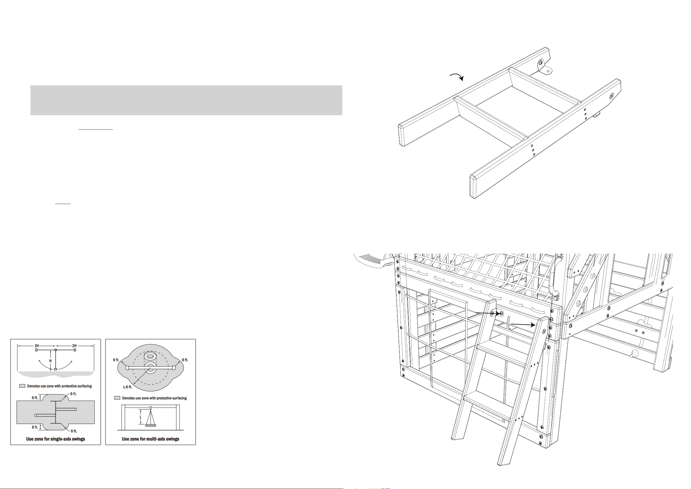
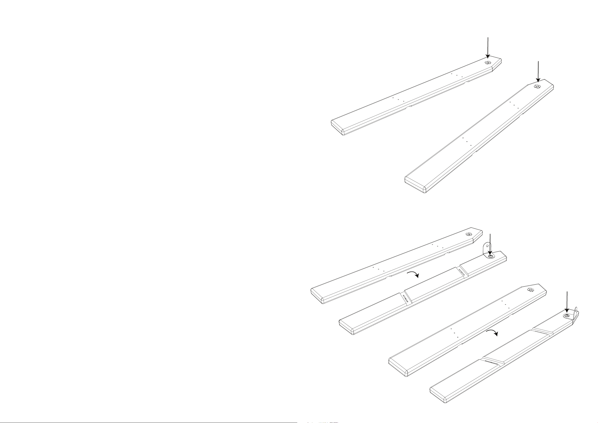
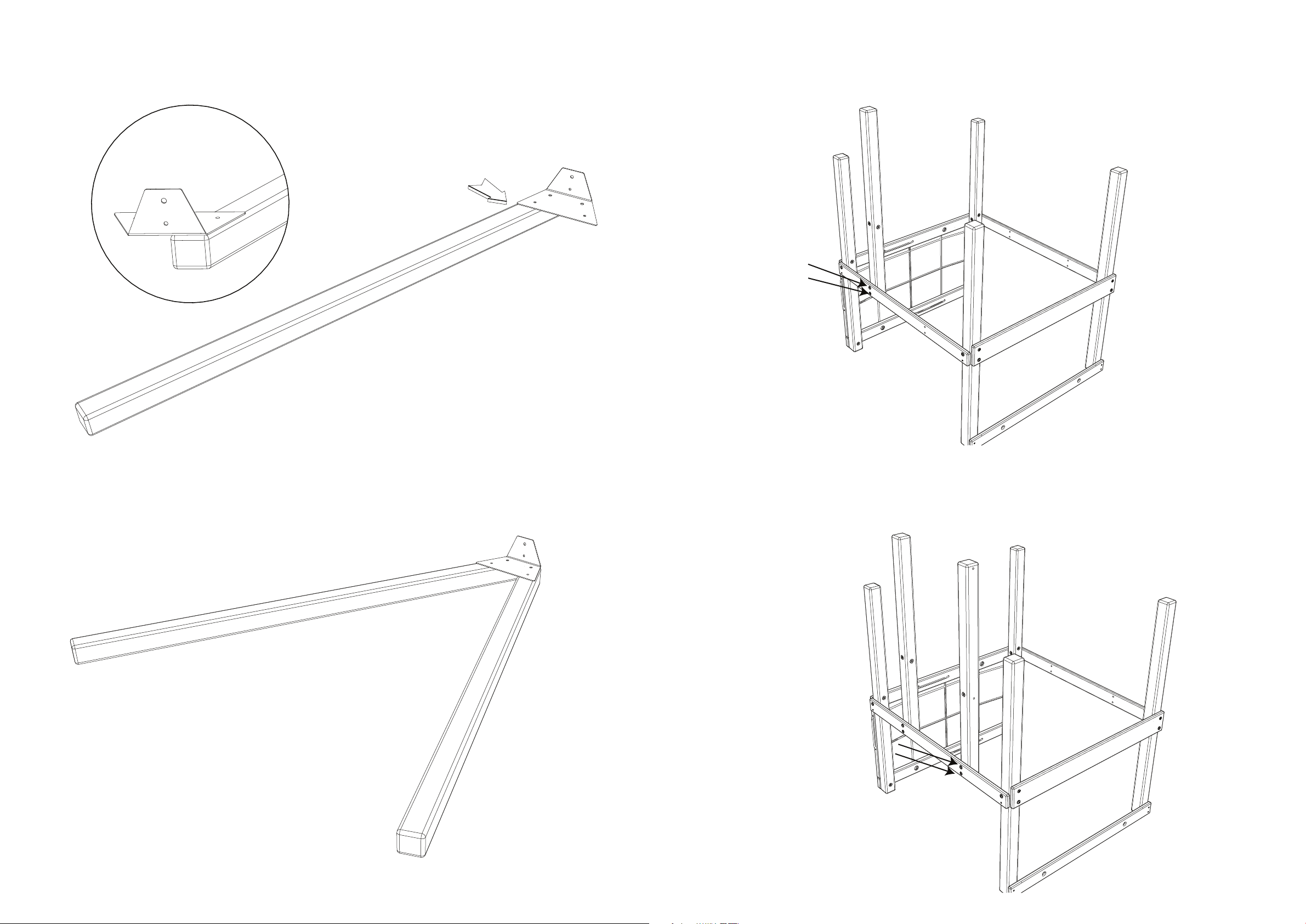
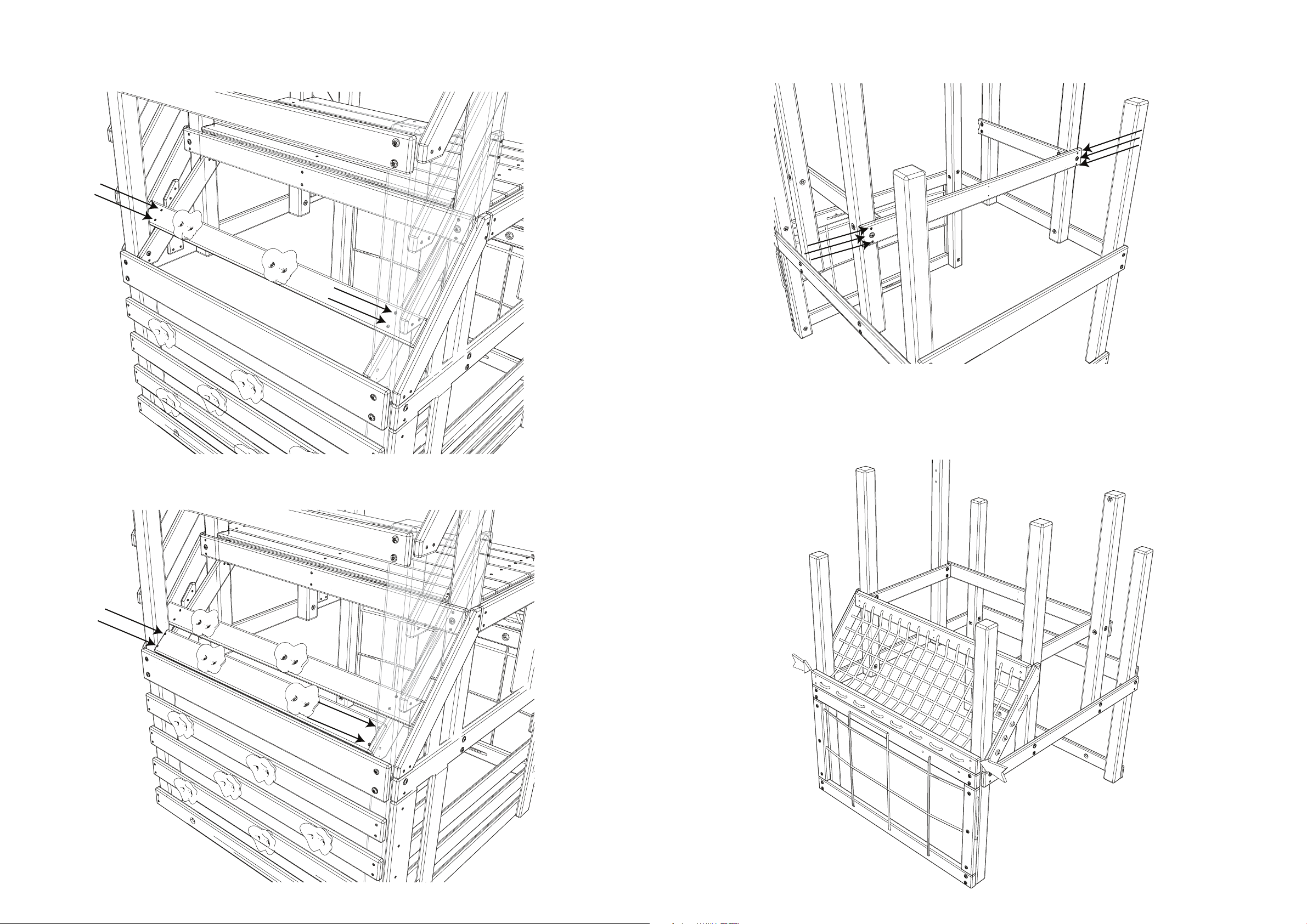
Step 113:
Carefully turn the Ladder over so the Rear Board is on the ground.
Step 114:
Align and attach the Ladder to the Lower Cargo Net Frame using (2) Bolts (B160).
180°
7
MAINTENANCE
THIRD PARTY ASSEMBLY
IMPORTANT SAFETY INFORMATION
• Tighten all hardware, but do not over-tighten to prevent splintering.
• Lubricate all metallic moving parts per manufacturer's instructions.
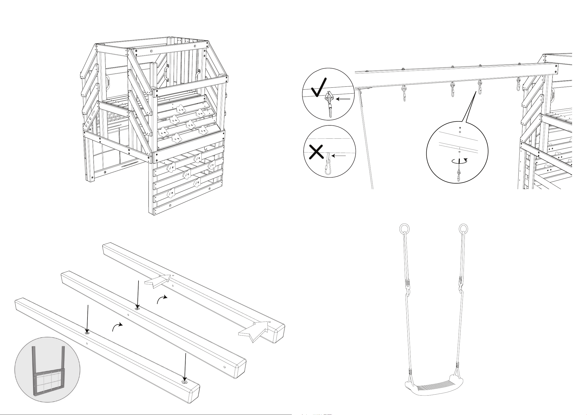
• Check that swing hanger bolts are secure and tight. Quick clips should be
completely closed and threaded clips screwed tight. Ropes should be
secure at both ends so they cannot loop back and create an entrapment.
• Check all protective coverings on bolts, pipes, edges and corners. Replace
if they are loose, cracked or missing.
• Check for sharp edges or protruding screw threads. Add washers if
required.
• Check ground stakes for looseness, damage or deterioration. Ensure soil
conditions are adequate to rmly hold the stakes. Firmly anchor unit to
the ground during use. Re-secure or replace if necessary.
• Check all moving parts including swing seats, ropes, cables, and chains
for wear, rust or other deterioration. Replace as needed.
• Check metal parts for rust. If found, sand and repaint using a non-lead
based paint which complies with 16 CFR 1303.
• Check all wood pieces for deterioration and splinters. Sand down
splinters and replace deteriorating wood.
• Reinstall any plastic parts, such as swing seats or any other items that
were removed for the cold season.
• Rake and check depth of loose ll protective surfacing materials to
prevent compaction and to maintain appropriate depth. Replace as
necessary.
Should you elect to use a third party person or service to assemble this product, the manufacturer assumes no responsibility or liability for any charge
incurred for any assembly services. Please see our warranty for more information about damaged and missing part replacement coverage. Little Tikes will not
reimburse the customer for the price of parts purchased.
• Tighten all hardware, but do not over-tighten to prevent splintering.
• Check all protective coverings on bolts, pipes, edges and corners. Replace
if they are loose, cracked or missing. Check bolt covers for sharp edges.
Replace as needed.
• Check for sharp edges or protruding screw threads. Add washers if
required.
• Rake and check depth of loose ll protective surfacing materials to
prevent compaction and to maintain appropriate depth. Replace as
necessary.
• Check all moving parts including swing seats, ropes, cables, and chains
for wear, rust or other deterioration. Replace as needed.
• Lubricate all metallic moving parts per manufacturer's instructions.
At the beginning of each play season:Twice a month during play season:
• Check the swing beam and hardware every two weeks due to wood
expansion and contraction. It is particularly important that this
procedure be followed at the beginning of each season.
• Inspect wood parts monthly. The grain of the wood sometimes will lift in
the dry season causing splinters to appear. Light sanding may be
necessary to maintain a safe play environment. Treat your unit with
stain regularly to help prevent severe splitting and other damage.
• A waterborne transparent stain has been applied to your unit. This is
done for color only. Once or twice a year, depending on your climate
conditions, you must apply some protection (sealant) on your unit. Prior
to the application of the sealant, lightly sand any rough spots on your
unit. Please note this is a requirement of your warranty.
• Assembling and maintaining the unit on a level surface is very
important. As your children play, your unit will slowly dig its way into
the soil, and it is very important that it settles evenly. Make sure the unit
is level once each year or at the beginning of each play season.
Additional Maintenance:
• Remove plastic swing seats and other items as specied by the
manufacturer and take indoors. Plastic components may become more
brittle in cold conditions.
• Rake and check depth of loose ll protective surfacing materials to
prevent compaction and to maintain appropriate depth. Replace as
necessary.
At the end of each play season:
* Or when the temperature falls below 32º F
Owners MUST maintain the legibility of the warning labels.
DISPOSAL
Once you no longer desire to play with or keep the unit, it
should be disassembled and disposed of in such a way
that no unreasonable hazards exist at the time the unit is
discarded. Follow local waste ordinances.
WOOD WEATHERING
Although the manufacturer has taken great care in selecting premium lumber, wood is a product of nature and is susceptible to weathering. As the climate
changes, moisture moves in and out of the wood, causing tension which can result in checking and warping.
• Checking: Surface cracks in the wood along the grain.
• Warping: Distortion from the original plane of the board. This usually happens from wetting and drying of the wood.
• Fading: A natural change in the wood color as it is exposed to sunlight. Wood may turn gray over time.
The factory-applied coating will decrease over time due to water absorption and sunlight. Apply a water repellent or stain on a yearly basis. Most weathering
is a normal result of nature and will not aect safe and enjoyable play on this unit. If you have any concerns about weathering, contact consumer service.
ONLY REPLACE DAMAGED OR DEFECTIVE PRODUCT PARTS ACCORDING TO THE MANUFACTURER’S INSTRUCTIONS.
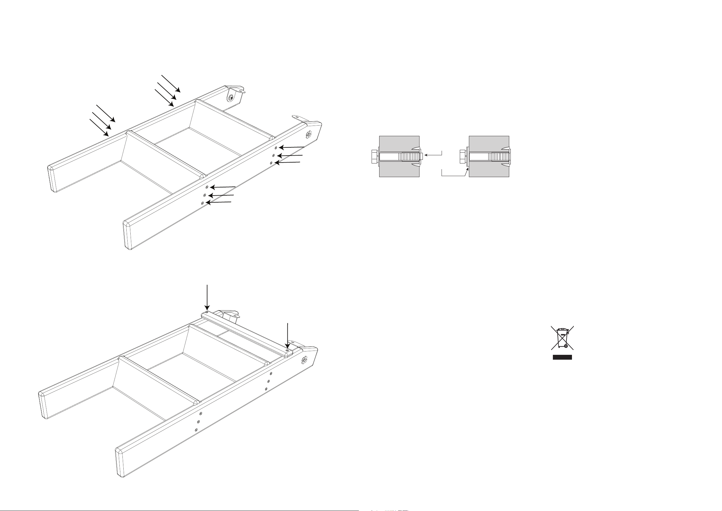
IF BOLT PROTRUDES
BEYOND T-NUT
USE AN EXTRA
FLAT WASHER
66
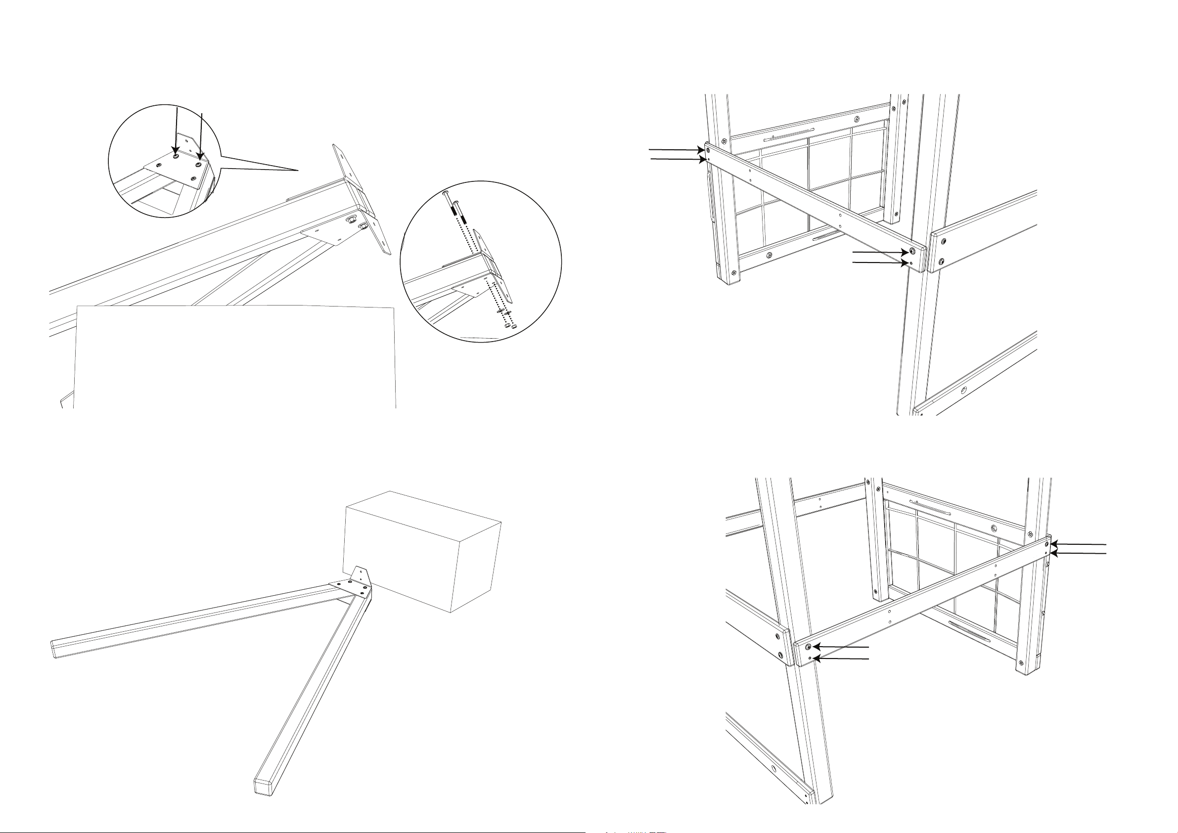
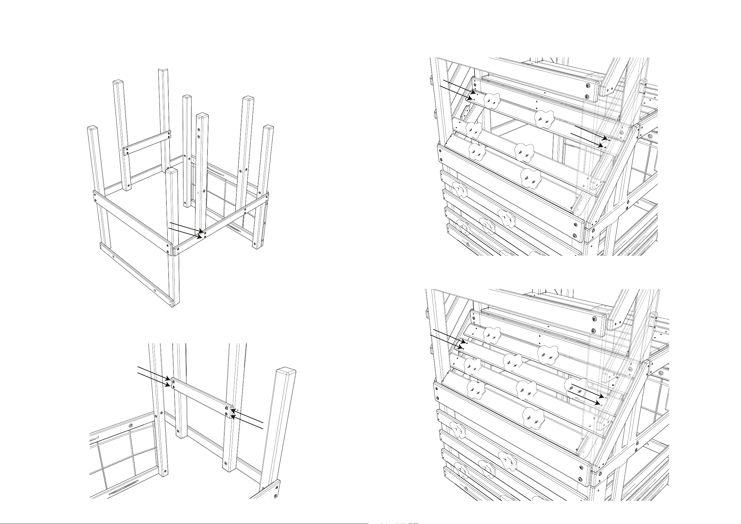
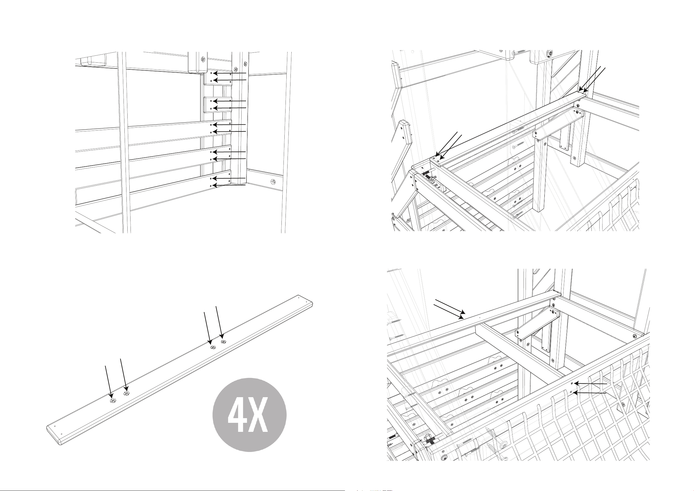
Step 111:
Align the Left and Right Uprights. Note the location of the angled edges. Insert (2) Ladder Rungs (029)
into the grooves of the Left and Right Uprights. Attach the Ladder Rungs using (12) Screws (S92).
Step 112:
Attach (1) Rear Board (031) to the Uprights using (2) Screws (S95).
8
LIMITED WARRANTY
The Little Tikes Company makes fun, high quality toys. We warrant to the original purchaser that this product is free of defects in materials or workmanship for one year from
the date of purchase (dated sales receipt is required for proof of purchase). In addition, all wood carries a pro-rated 5 year warranty against rot and decay. Please contact
consumer service for any charges associated with replacement parts under this warranty. All other parts, such as hardware, swings, rides, accessories, and slides carry a one
year warranty. The Little Tikes Company will replace any parts within the rst 90 days from the date of purchase if they are found to be missing from the original packaging or
damaged upon receipt.
This warranty applies to the original owner and registrant and is non-transferable. Regular maintenance is required to assure maximum life and performance of this product,
and failure by the owner to maintain the product according to the maintenance requirements may void this warranty. Maintenance guidelines are provided in this manual.
This limited warranty does not cover:
• Labor for any inspection
• Labor for replacement of any defective item(s)
• Incidental or consequential damage
• Cosmetic defects which do not aect performance or integrity of a part or the entire product
• Vandalism, improper use, failure due to loading or use beyond the capacities stated in this manual
• Acts of nature including but not limited to wind, storms, hail, floods or excessive water exposure
• Improper installation including but not limited to installation on uneven, unlevel or soft ground
• Minor twisting, warping, checking or any other natural occurring properties of wood that do not affect performance or integrity
This warranty is valid only if the product has been assembled and maintained per the instructions. Any modications made to the original product could damage the structural
integrity of the unit, leading to failure and possible injury. Making modications to this unit voids the warranty. The Little Tikes Company disclaims all other representations
and warranties of any kind, express or implied.
RESIDENTIAL HOME USE ONLY. This unit is not intended for public use. The manufacturer does not warranty this product if it is used for commercial purposes like daycare,
schools, churches, nurseries or parks.
U.S.A and Canada: For warranty service or replacement part information, please visit our website at www.littletikes.com, call 1-800-321-0183 or write to: Consumer Service,
The Little Tikes Company, 2180 Barlow Road, Hudson OH 44236, U.S.A. Some replacement parts may be available for purchase after warranty expires—contact us for details.
Outside U.S.A and Canada: Contact place of purchase for warranty service.
This warranty gives you specic legal rights, and you may also have other rights, which vary from country/state to country/state. Some countries/states do not allow the
exclusion or limitation of incidental or consequential damages, so the above limitation or exclusion may not apply to you.
65
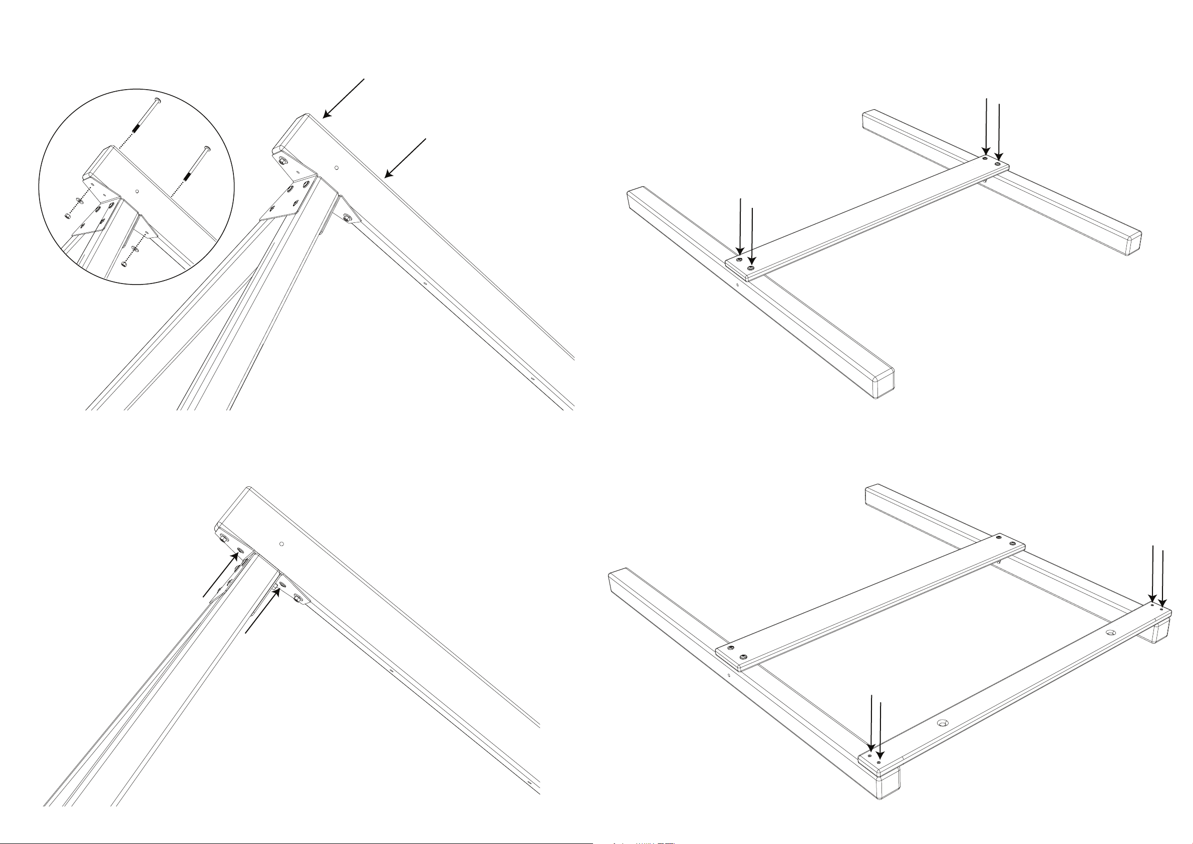
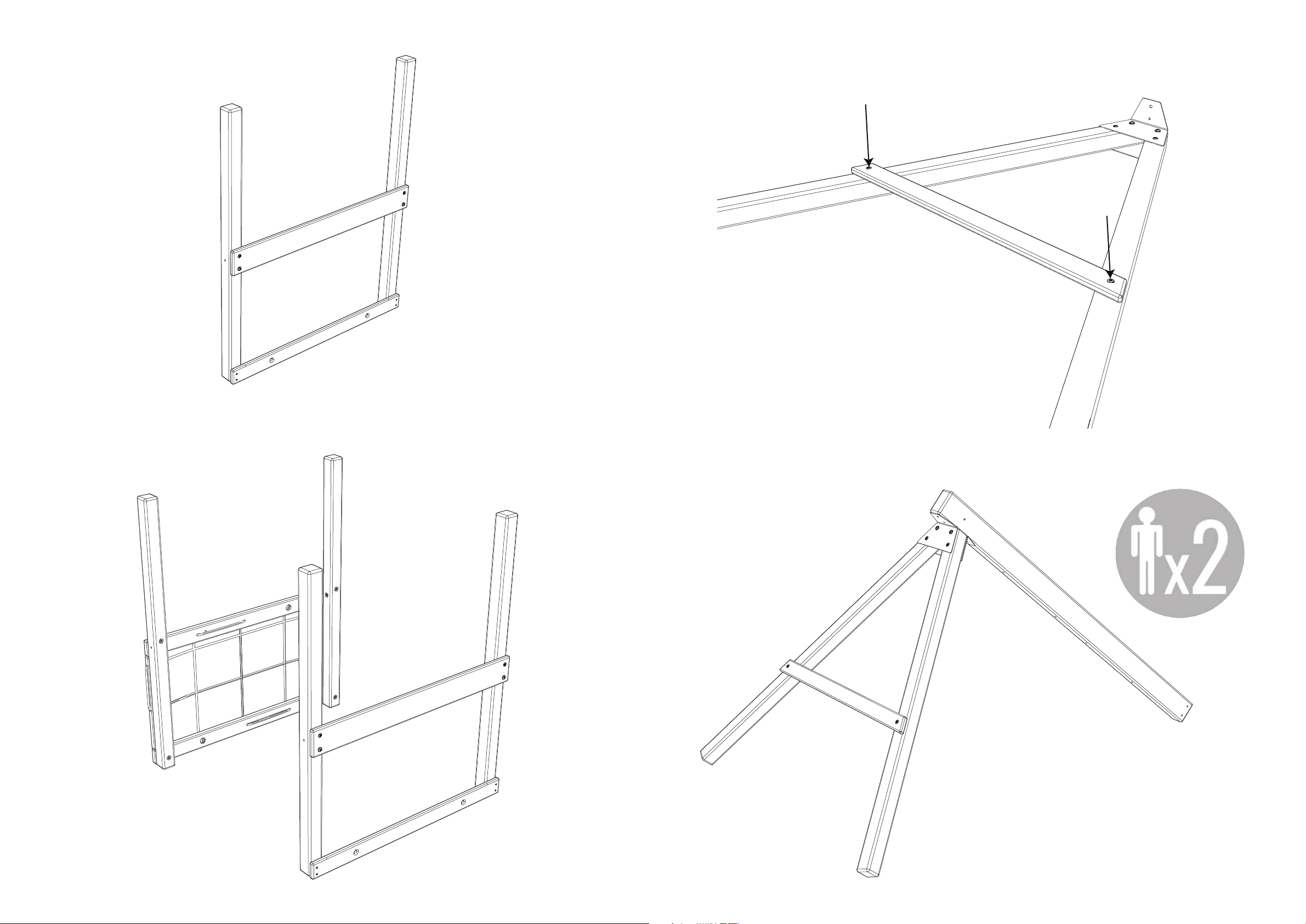
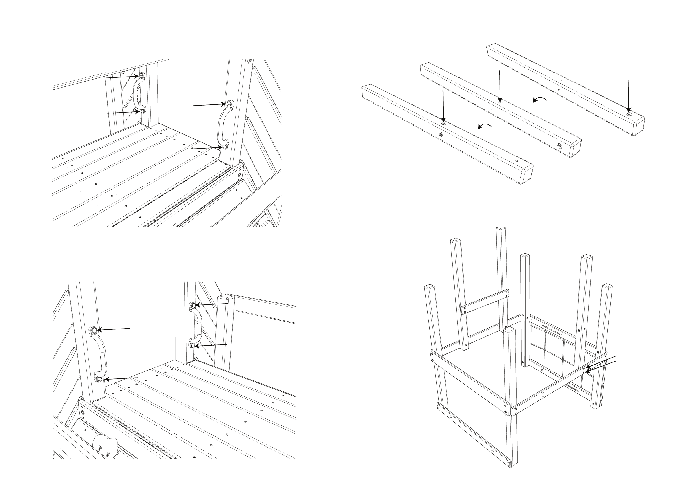
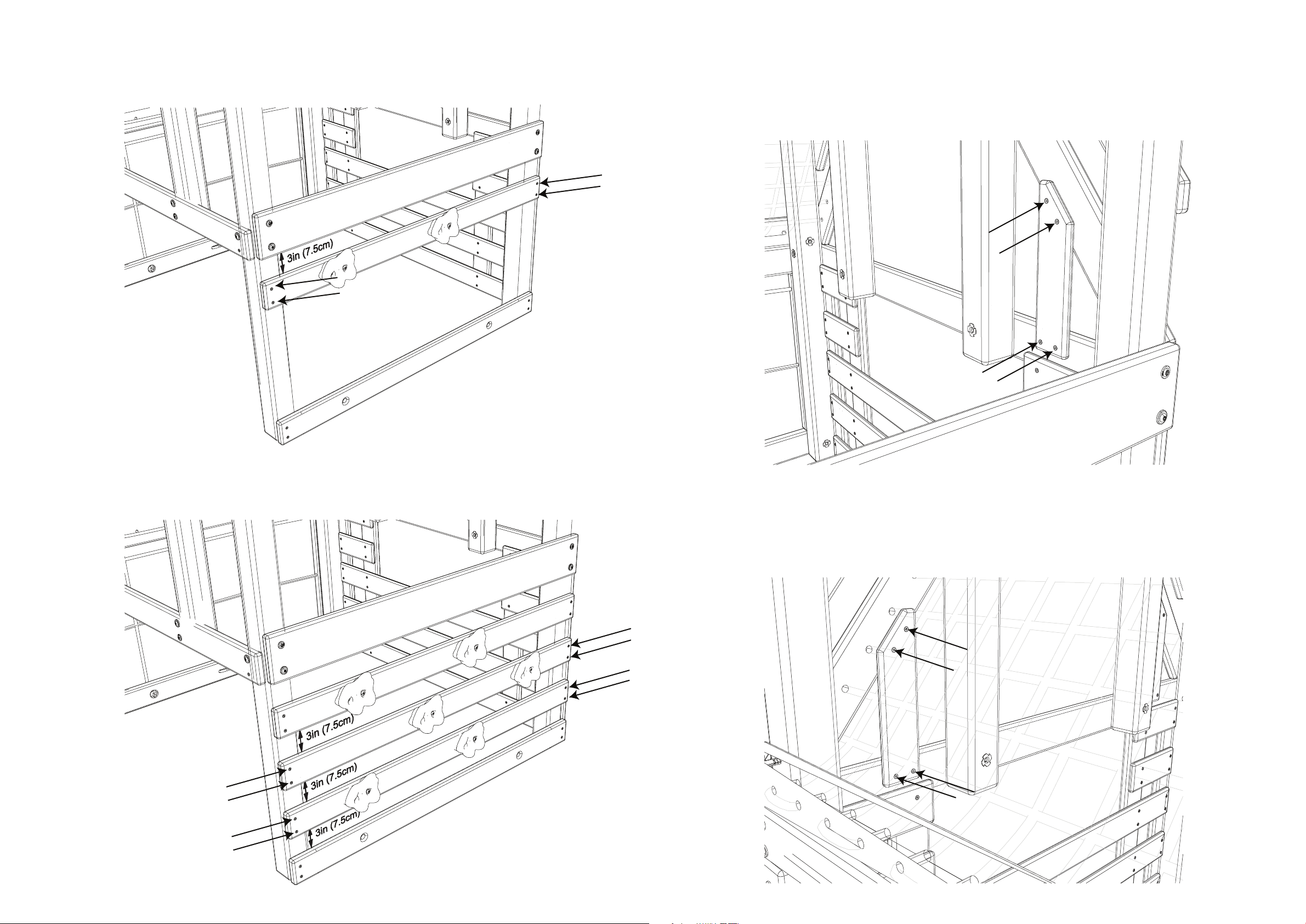
Step 109:
Insert (1) Nut (N02) into (1) Right Upright (030) and (1) Left Upright (028).
Step 110:
Rotate the Left and Right Uprights so each Nut is on the ground. Attach (1) Bracket (PC-HD27) to each
Upright using (1) Bolt (B159).
180°
180°
9
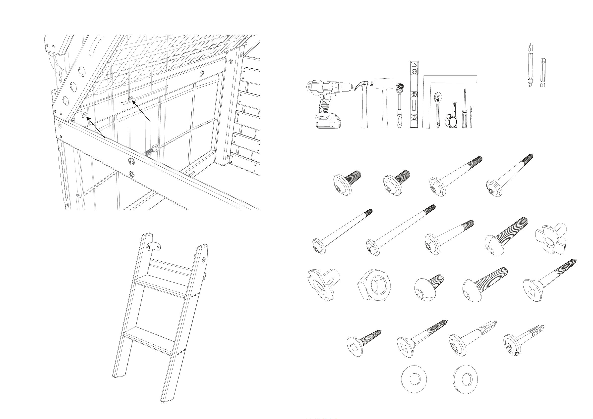
TOOLS
HARDWARE
TOOLS YOU WILL NEED (NOT INCLUDED)
Hardware listed is the quantity needed to build the unit. Extra hardware is included.
To complete this procedure, you will need a Power Drill, a Hammer, a
Rubber Mallet, a Metric Socket Wrench Set, a Level, a Square, an
Adjustable Wrench, a Tape Measure and a Ladder (not pictured).
Optionally, you may need a Flathead Screwdriver and a 3/16in Drill Bit.
Gebruikershandleiding.com neemt misbruik van zijn services uitermate serieus. U kunt hieronder aangeven waarom deze vraag ongepast is. Wij controleren de vraag en zonodig wordt deze verwijderd.
Product:
Spelregels forum
Om tot zinvolle vragen te komen hanteren wij de volgende spelregels:
lees eerst de handleiding door;
controleer of uw vraag al eerder door iemand anders is gesteld;
probeer uw vraag zo duidelijk mogelijk te stellen;
heeft u een probleem en al geprobeerd om dit op te lossen, vermeld dit erbij aub;
heeft u een oplossing gekregen van een bezoeker dan horen wij dat graag in dit forum;
wilt u een reactie geven op een vraag of antwoord, gebruik dan niet dit formulier maar klik op de knop 'reageer op deze vraag';
uw vraag wordt direct op de website gezet; vermijd daarom persoonlijke gegevens in te vullen;
Belangrijk! Als er een antwoord wordt gegeven op uw vraag, dan is het voor de gever van het antwoord nuttig om te weten als u er wel (of niet) mee geholpen bent! Wij vragen u dus ook te reageren op een antwoord.
Belangrijk! Antwoorden worden ook per e-mail naar abonnees gestuurd. Laat uw emailadres achter op deze site, zodat u op de hoogte blijft. U krijgt dan ook andere vragen en antwoorden te zien.
Abonneren
Abonneer u voor het ontvangen van emails voor uw Little tikes 656200 Panther Peak bij:
nieuwe vragen en antwoorden
nieuwe handleidingen
U ontvangt een email met instructies om u voor één of beide opties in te schrijven.
Ontvang uw handleiding per email
Vul uw emailadres in en ontvang de handleiding van Little tikes 656200 Panther Peak in de taal/talen: Engels als bijlage per email.
De handleiding is 14.47 mb groot.
U ontvangt de handleiding per email binnen enkele minuten. Als u geen email heeft ontvangen, dan heeft u waarschijnlijk een verkeerd emailadres ingevuld of is uw mailbox te vol. Daarnaast kan het zijn dat uw internetprovider een maximum heeft aan de grootte per email. Omdat hier een handleiding wordt meegestuurd, kan het voorkomen dat de email groter is dan toegestaan bij uw provider.
Stel vragen via chat aan uw handleiding
Stel uw vraag over deze PDF
Uw handleiding is per email verstuurd. Controleer uw email
Als u niet binnen een kwartier uw email met handleiding ontvangen heeft, kan het zijn dat u een verkeerd emailadres heeft ingevuld of dat uw emailprovider een maximum grootte per email heeft ingesteld die kleiner is dan de grootte van de handleiding.
Er is een email naar u verstuurd om uw inschrijving definitief te maken.
Controleer uw email en volg de aanwijzingen op om uw inschrijving definitief te maken
U heeft geen emailadres opgegeven
Als u de handleiding per email wilt ontvangen, vul dan een geldig emailadres in.
Uw vraag is op deze pagina toegevoegd
Wilt u een email ontvangen bij een antwoord en/of nieuwe vragen? Vul dan hier uw emailadres in.