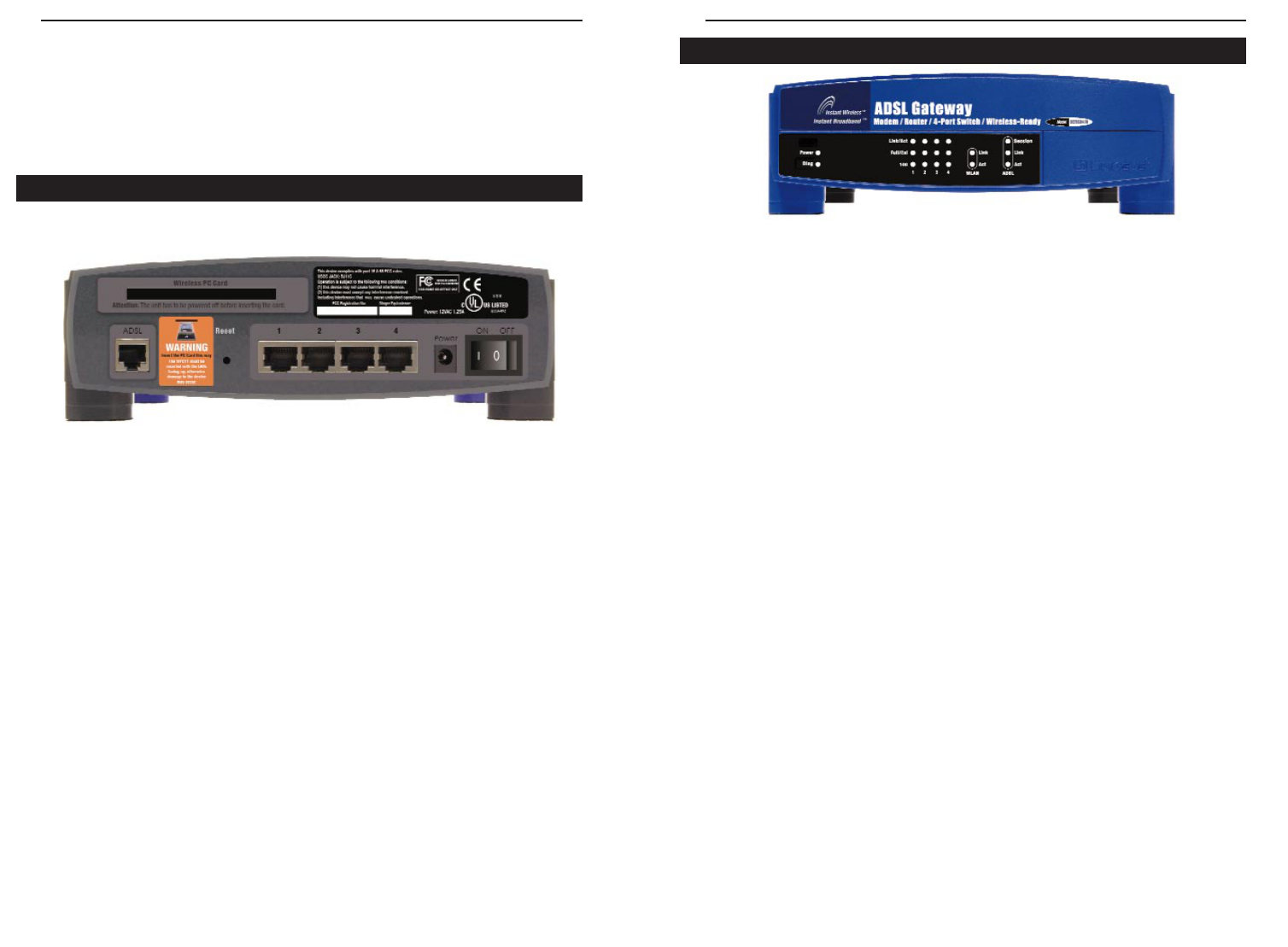
ADSL Gateway with Modem / Router / 4-Port Switch / Wireless-Ready
61
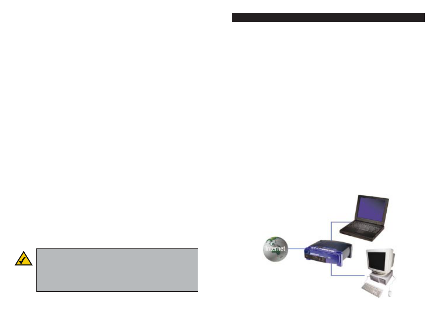
Instant Broadband
™
Series
60
I set up an Unreal Tournament Server, but others on the LAN cannot join. What do
I need to do? If you have a dedicated Unreal Tournament server running, you
need to create a static IP for each of the LAN computers and forward ports
7777, 7778, 7779, 7780, 7781, and 27900 to the IP address of the server. You
can also use a port forwarding range of 7777 ~ 27900. If you want to use the
UT Server Admin, forward another port (8080 usually works well but is used
for remote admin. You may have to disable this.), and then in the
[UWeb.WebServer] section of the server.ini file, set the ListenPort to 8080 (to
match the mapped port above) and ServerName to the IP assigned to the
Gateway from your ISP.
Can multiple gamers on the LAN get on one game server and play simultaneously
with just one public IP address? It depends on which network game or what
kind of game server you are using. For example, Unreal Tournament supports
multi-login with one public IP.
How do I get
Half-Life:Team Fortress
to work with the Gateway? The default client
port for Half-Life is 27005. The computers on your LAN need to have
“+clientport 2700x” added to the HL shortcut command line; the x would be
6, 7, 8, and on up. This lets multiple computers connect to the same server.
One problem: Version 1.0.1.6 won’t let multiple computers with the same CD
key connect at the same time, even if on the same LAN (not a problem with
1.0.1.3). As far as hosting games, the HL server does not need to be in the
DMZ. Just forward port 27015 to the local IP address of the server computer.
The web page hangs; downloads are corrupt, or nothing but junk characters are
being displayed on the screen. What do I need to do? Force your Ethernet
adapter to 10Mbps or half duplex mode, and turn off the “Auto-negotiate”
feature of your Ethernet adapter as a temporary measure. (Please look at the
Network Control Panel in your Ethernet adapter’s Advanced Properties tab.)
Make sure that your proxy setting is disabled in the browser. Check our web-
site at www.linksys.com for more information.
If all else fails in the installation, what can I do? Reset the Gateway by holding
down the reset button until the Diag LED fully turns on and off. Obtain and
flash the latest firmware release that is readily available on the Linksys web-
site, www.linksys.com.
How will I be notified of new Gateway firmware upgrades? All Linksys firmware
upgrades are posted on the Linksys website at www.linksys.com, where they
can be downloaded for free. The Gateway’s firmware can be upgraded with
TFTP programs.
What is the maximum number of IP addresses that the Gateway will support? The
Gateway will support up to 253 IP addresses.
Is IPSec Pass-Through supported by the Gateway?Yes, it is a built-in feature that
the Gateway automatically enables.
Does the Gateway support IPX or AppleTalk? No. TCP/IP is the only protocol
standard for the Internet and has become the global standard for communica-
tions. IPX, a NetWare communications protocol used only to route messages
from one node to another, and AppleTalk, a communications protocol used on
Apple and Macintosh networks, can be used for LAN to LAN connections,
but those protocols cannot connect from WAN to LAN.
What is Network Address Translation and what is it used for? Network Address
Translation (NAT) translates multiple IP addresses on the private LAN to one
public address that is sent out to the Internet. This adds a level of security
since the address of a PC connected to the private LAN is never transmitted
on the Internet. Furthermore, NAT allows the Gateway to be used with low
cost Internet accounts, when only one TCP/IP address is provided by the ISP.
The user may have many private addresses behind this single address provid-
ed by the ISP.
Does the Gateway support any operating system other than Windows 95,Windows
98, Windows 2000, Windows NT, or Windows XP? Yes, but Linksys does not, at
this time, provide technical support for setup, configuration or troubleshoot-
ing of any non-Windows operating systems.
Does the Gateway support ICQ send file? Yes, with the following fix: click ICQ
menu -> preference -> connections tab->, and check I am behind a fire-
wall or proxy. Then set the firewall time-out to 80 seconds in the firewall set-
ting. The Internet user can then send a file to a user behind the Gateway.
How do I get Napster to work with the Gateway? Napster is fully compatible with
the Gateway, but you must make sure that, during installation, you select “no
idea” when asked about your firewall selection. Set your proxy settings to
“No Proxy Server” in your File>Preferences.
Frequently Asked Questions