Cleaners should not contain chlorine. Damage may occur.
Food spills should be cleaned as soon as entire grill is cool. Spills may
cause permanent discoloration.
Cleaning Method:
■Rub in direction of grain to avoid scratchin
g or damaging the
surface.
■Stainless steel clea
ner
■Liquid detergent or all-purpose cleaner:
■Rinse with clean water and dry with soft, lint-free cloth.
■Vinegar to remove
hard water spots.
■Glass cleaner to remove fingerprints.
GRILL GRATES
IMPORTANT: To avoid damage to grill grates, do not use a steel or
fiber scraper. Immediately after you are finished cooking, loosen food
soil with a brass bristle brush. Turn all burners to HI for 10-15 minutes
with the hood closed to burn off food soil. Turn off all burners, raise the
hood and let grates cool. Use the brass bristle brush to remove ash from
the grill grates.
When completely cool, grill racks can be removed for thorough
cleaning. Clean them with a mild detergent and warm water.
For baked-on soil, prepare a solution of
1 cup (250 mL) ammonia to 1
gal. (3.75 L) water. Soak grates for 20 minutes, then rinse with water and
dry completely.
WARMING SH
ELF
Cleaning Method:
■Liquid detergent or an all-purpose cleaner.
■Rinse with clean water and dry with soft, lint-free cloth.
■For tough spots or baked-on grease, use a commercial degreaser
designed for stainless steel.
IMPORT
ANT: Make sure gas supply is off and all control knobs are in
the Off position.
EXTERIOR
The quality of this ma
terial resists most stains and pitting, providing that
the surface is kept clean, polished and covered.
■Apply stainless steel polish to all non-cooking areas before first use.
Reapply after each cleaning to avoid permanent damage to surface.
■Cleaning should always be followed by rinsing with clean warm
water.
■Wipe the surface completely dry with a soft cloth.
■For tough spots or baked-on grease, use a commercial degreaser
designed for stainless steel.
INTERIOR
Discoloration of stainless steel on these parts is to be expected, due to
intense heat
from the burners. Always rub in the direction of the grain.
Cleaning should always be followed by rinsing with clean, warm water.
Cleaning Method:
■Liquid detergent or all-purpose cleaner.
■Rinse with clean water and dry completely with
a soft, lint-free
cloth.
■A heavy-duty scrub sponge can be used with mild cleaning products.
■For small, diffic
ult-to-clean areas, use a commercial degreaser
designed for stainless steel.
26
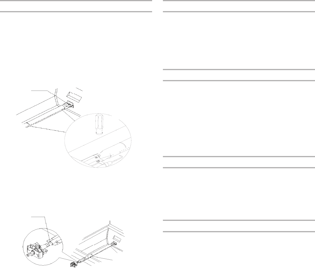
BURNERS
Cleaning Method:
■
Clean the exterior of the burner with a wire brush.
■Clear any clogged burner ports with a straightened paper clip.
■Do not use a toothpick as it may break off and clog the port.
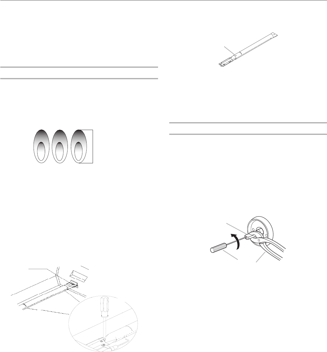
■Check and clean burner/venturi tubes.
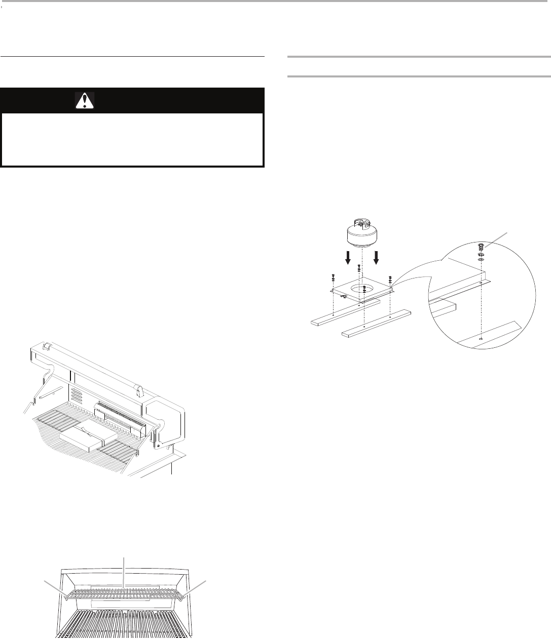
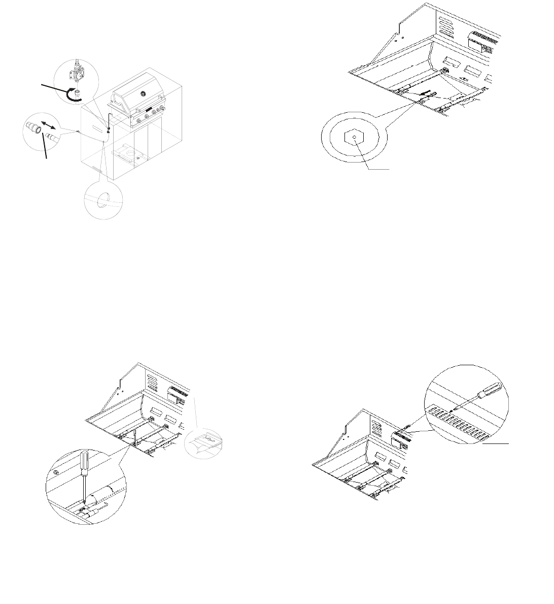
1.Remove grill grates and flame tamers.
2.Remove the screw and clip that hold the burner in place.
Remove gas burner from the grill.
A.Clip
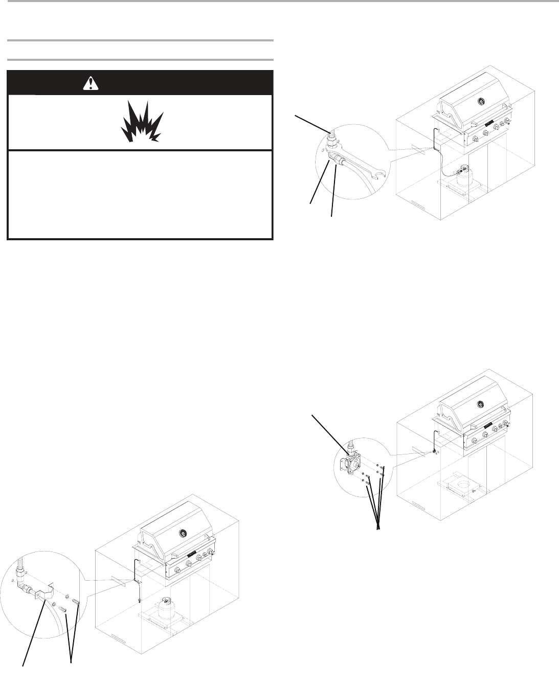
3.Use a flashlight to inspect into the burner through the burner
inlet to ensure there is no blockage. If any obstruction is seen,
use a metal coat hanger that has been straightened to clear them.
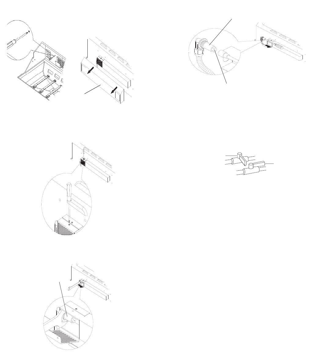
4.After inspecting the inside of burner for blockage, reassemble
burner by sliding the middle tube of the gas burner over the gas
orifice.
A.Burner/orifice connection
5.Reattach gas burner using screw and clip.
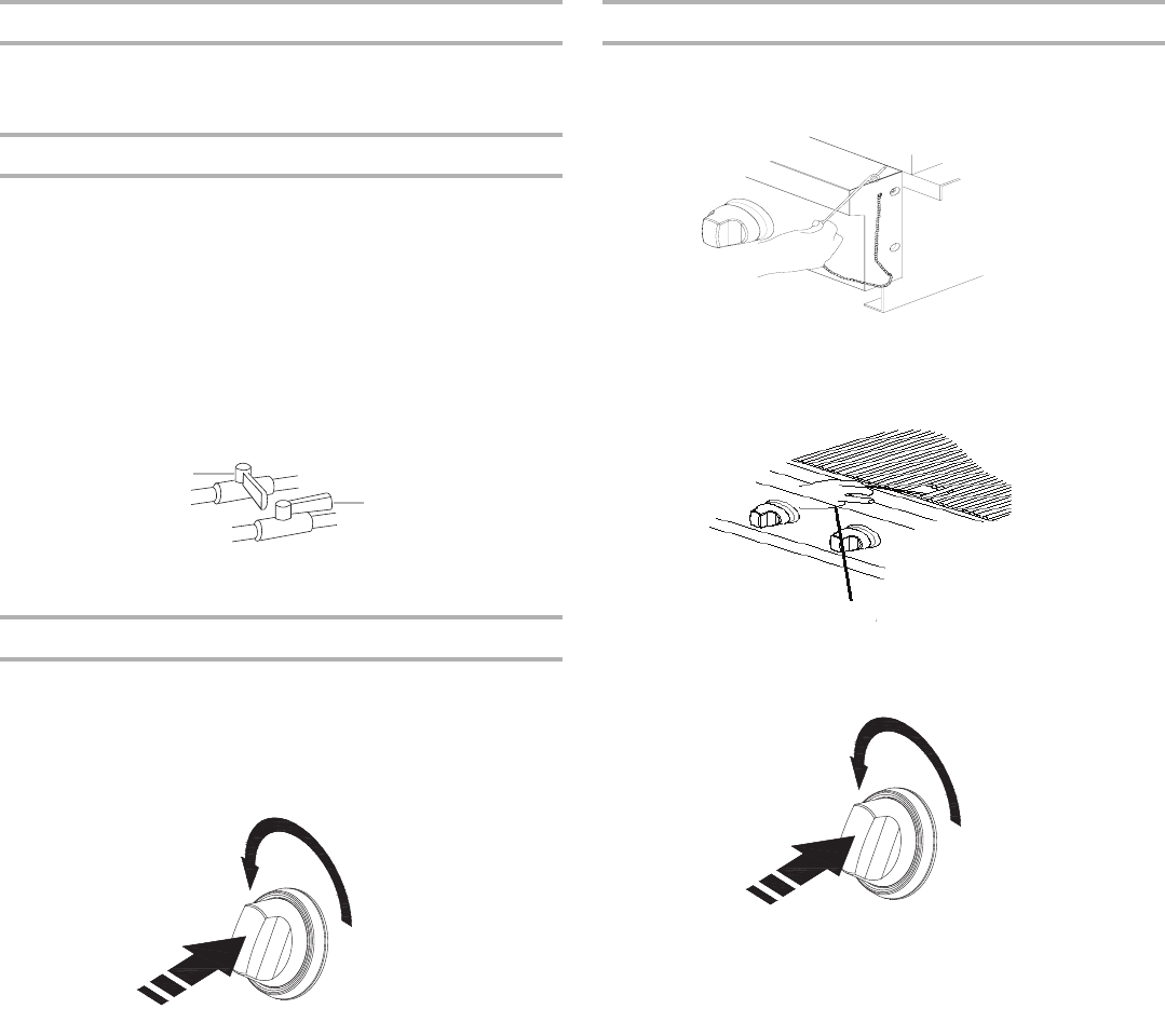
ROTISSIERE BURNER
Cleaning Method:
1.Light the rotisserie burner. See the “Usin
g Your Rotisserie Burner”
section.
2.Clo
se the grill hood.
3.Leave the burner on high for approximately 30 minutes.
4.Turn knob to OFF and let cool completely.
5.
Brush off ash particles from the rotisserie burner.
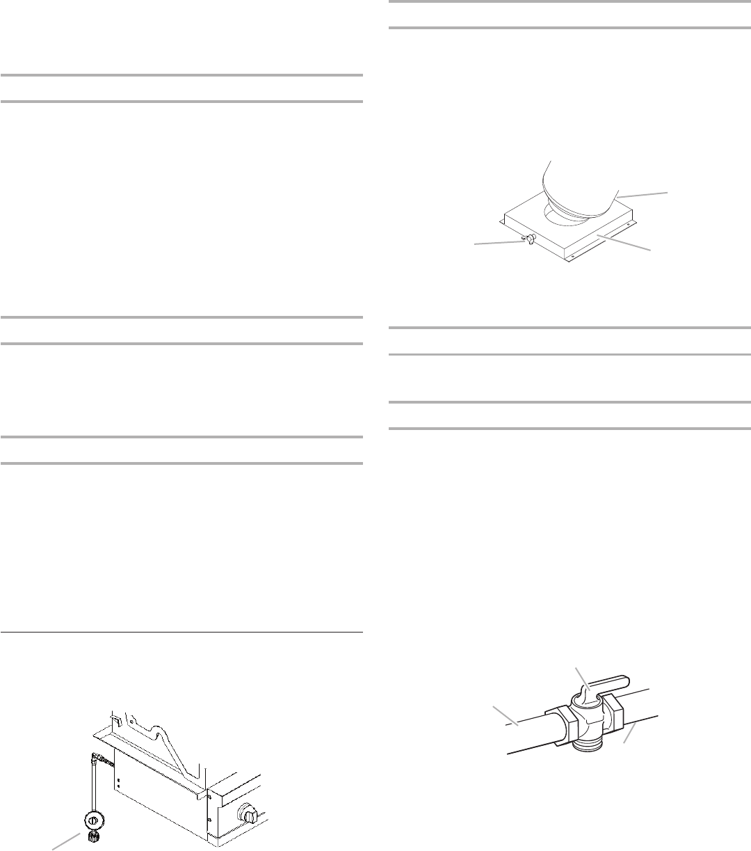
GREASE CUP
IMPORTANT: The grease cup should only be removed when grill is
completely cool.
The grease cup collects grease and food particles that fall through the grill.
Cl
ean often to avoid grease buildup.
Cleaning Method:
■Remove cup and set on a
flat surface.
■Wipe excess grease with paper towels.
■Mild detergent and warm water. Ri
nse and dry thoroughly.
■Replace cup
KNOBS AND FLANGE AREA AROUND KNOBS
IMPORTANT: To avoid damage to k
nobs or flange area around knobs,
do not use steel wool, abrasive cleaners, or oven cleaner.
Do not soak knobs.
Cleaning Method:
■Mild detergent,
a soft cloth and warm water.
■Rinse and dry.
CONTROL PANEL GRAPHICS
IMPORTANT: To avoid d
amage to control panel graphics, do not use
steel wool, abrasive cleaners or oven cleaner.
Do not spray cleaner directly onto panel.
Cleaning Method:
■Clean around the burner labels gently; scrubbing may remove
printing.
■Mild detergent, soft cloth and warm water.
■Rinse and dry.
A
A
27
TR
OUBLESHOOTING
Grill will not light
■
Is the 20 lb LP gas fuel tank valve turned
off?!
Turn the 20 lb LP gas fuel tank on.
■Is the grill proper
ly connected to the gas supply?!
Contact a trained repair specialist or see Installation Instructions.
■Is there gas in the 20 lb LP gas fuel tank?!
Check the gas level.
■Is the igniter working?!
Check that the igniter battery is properly installed or check to see if
the battery needs to be replaced. See the “Replacing the Igniter
Battery” section.
Check to see if the grill will match-light. See “Manually Lighting
the Main Grill” in the “Outdoor Grill Use” section.
Check for loose wire connections to the igniter or electrodes.
Check to see if debris is blocking the electrodes.
If a spark occurs anywhere but the igniter tip, replace
the igniter.
Burner flame will not stay lit
■Is the gas supply fully turned on?!
Check that the
20 lb LP gas fuel tank valve is fully open.
■Is the gas supply in the 20 lb LP fuel gas tank low?!
Check the gas level.
■Is the burner properly installed and in good condition?!
Check that the bu
rner is installed properly. Check for defects in the
burner.
Flame is noisy, low or erratic
■Is the gas supply fully turned on?!
Check that the 20 lb LP gas fuel tank valve is fully open.
■Is the gas supply in the 20 lb LP fuel gas tank low?!
Check the gas level.
■Does only one burner appear low?!
Check and clean the burner ports if clogged or dirty. See “Gener
al
Cleaning” section.
■Is the gas supply hose bent or
kinked?!
Straighten the gas supply hose.
■Is the flame noisy or lifting away fr
om the burner?!
Burner may be getting too much air. Check the air shutter
adjustment, see “Check and Adjust Burners” section.
■Is the burner flame mostly yellow or orange?!
Grill may be in an area that is too windy, or not receiving enough air.
Check the burner air inlets for obstructions. Check the air shutter
adjustment, see “Check and Adjust Burners” section.
Excessive flare-ups
■Is there excessive fat in the food being grilled?!
Keep flame on low or turn one burner off.
Keep the hood up when grilling to avoid excessive flare-ups.
Move food to the warming rack until flames subside.
To avoid damage to the grill, do not spray water on gas flames.
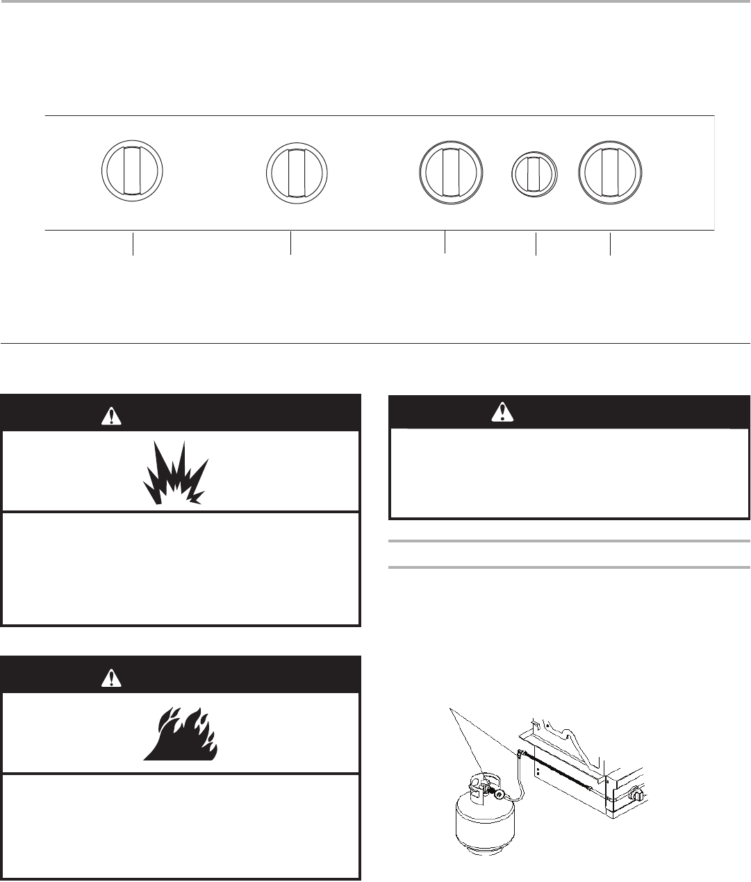
Low heat
LP Gas:
For outdoor grills using a 20 lb LP gas fuel tank, slowly open
the tank
valve.
NOTE: If flow limiting device activates, your grill may not light. If your
grill does light, the flames will be low and will not heat properly.
1.Turn tank valve and all control knobs off and wait 30 seconds.
2.After shutting off the tank, very slowly open the tank valve and wait
5 seconds before lighting.
3.Light the burners one at a time. See “Lighting the Main Grill”
section.
Natural Gas:
Gas pressure is affected by size and length of the gas line from the house
to the grill. Contact a qualified gas technician to provide the Natural gas
supply to the selected grill location in accordance with the National Fuel
Gas Code ANSI Z223.1/NFPA54 - latest edition, and local codes.
ASSISTANCE
Before calling for assistance, please check “Troubleshooting.” If you
stil
l need help, follow the instructions below.
When calling, please know the purchase date and the complete model
and serial number of your appliance. This information will help us to
better respond to your request.
If you need replacement parts
If you have questions or need to order replacement parts, contact
Customer Service Center at 1-877-373-2301 or email to !
CustomerSericeGrillServices.com.
Please direct all correspondence to:
Nexgrill Industries, Inc.!
5270 Edison Avenue!
Chino, CA 91710
Please include a daytime phone numb
er in your correspondence.
Accessories
Rotisserie Kit (This is optional )
Order Part Number 790-0007A
28
LIMITED W
ARRANTY
Nexgrill warrants to the original consumer-purchaser only that this product (Model #740-0780) shall be free from defects in workmanship and
materials after correct assembly and under normal and reasonable home use for the periods indicated below beginning on the date of purchase. The
manufacturer reserves the right to require photographic evidence of damage, or that defective parts be returned, postage and or freight pre-paid by the
consumer, for review and examination.!
Stainless steel tube burners:
10 year LlMlTED warranty against perforation; Other burner (
Rotisserie): 1 year LIMITED warranty
against perforation.
Cooking grids: 3 Year LIMITED warranty; does not cover dropping, chipping, scratching, or surface damage.
Stainless steel parts: 3 Year LIMITED warranty against perforation; does not cover cosmetic issues like surface corrosion, scratches and rust.
All other parts: 1 Year LIMITED warranty (Includes, but not limited to, valves, frame, housing, cart, control panel, igniter, regulator, hoses); does not
cover chipping, scratching, cracking surface corrosion, scratches or rust. !
Upon consumer supplying proof of purchase as p
rovided herein, Manufacturer will repair or replace the parts which are proven defective during the
applicable warranty period. Parts required to complete such repair or replacement shall be free of charge to you except for shipping costs, as long as the
purchaser is within the warranty period from the original date of purchase. The original consumer-purchaser will be responsible for all shipping
charges of parts replaced under the terms of this limited warranty. This limited warranty is applicable in the United States only, is only available to the
original owner of the product and is not transferable. Manufacturer requires reasonable proof of your date of purchase. Therefore, you should retain
your sales receipt and/or invoice. If the unit was received as a gift, please ask the gift-giver to send in the receipt on your behalf, to the below address.
Defective or missing parts subject to this limited warranty will not be replaced without registration or proof of purchase. This limited warranty applies
to the functionality of the product ONLY and does not cover cosmetic issues such as scratches, dents, corrosions or discoloring by heat, abrasive and
chemical cleaners or any tools used in the assembly or installation of the appliance, surface rust, or the discoloration of stainless steel surfaces. Surface
rust, corrosion, or powder paint chipping on metal parts that does not affect the structural integrity of the product is not considered a defect in
workmanship or material and is not covered by this warranty. This limited warranty will not reimburse you for the cost of any inconvenience, food,
personal injury or property damage. If an original replacement part is not available, a comparable replacement part will be sent. You will be
responsible for all shipping charges of parts replaced under the terms of this limited warranty.
ITEMS MANUFACTURER WILL NOT PAY FOR:
■Service calls to your home.
■Repairs when your product is used for other than normal, single-family house
hold or residential use.
■Damage resulting from accident, alteration, misuse, lack of maintenance/cleaning, abuse, fire, flood, acts of God, improper installation, and
installation not in accordance with electrical or
plumbing codes or use of products not approved by the manufacturer.
■Any food loss due to product failures.
■Replacement parts or repair labor costs for units operated outside the United States or Canada.
■Pickup and delivery of your product.
■Postage fees or photo processing fees for ph
otos sent in as documentation.
■Repairs to parts or systems resulting from unauthorized modifications made to the product.
■The removal and/or reinstallation of your product.
■Shipping cost, standard or expedited, for warranty/non warranty and replacement parts.
DISCLAIMER OF IM
PLIED WARRANTIES; LIMITATION OF REMEDIES
Repair or replacement of defective parts is your exclusive remedy under the terms of this limited warranty. Manufacturer will not be responsible for
any consequential or incidental damages arising from the breach of either this limited warranty or any applicable implied warranty, or for failure or
damage resulting from acts of God, improper care and maintenance, grease fire, accident, alteration, replacement of parts by anyone other than
installation or installation not in accordance with local codes or printed manufacturer instructions.
THIS LIMITED WARRANTY IS THE SOLE EXPRESS WARRANTY GIVEN BY THE MANUFACTURER. NO PRODUCT PERFORMANCE
SPECIFICATION OR DESCRIPTION WHEREVER APPEARING IS WARRANTED BY MANUFACTURER EXCEPT TO THE EXTENT SET
FORTH IN THlS LIMITED WARRANTY. ANY IMPLIED WARRANTY PROTECTION ARISING UNDER THE LAWS OF ANY STATE,
INCLUDING IMPLIED WARRANTY OF MERCHANTABILITY OR FITNESS FOR A PARTICULAR PURPOSE OR USE, IS HEREBY
LIMITED IN DURATION TO THE DURATION OF THIS LIMITED WARRANTY.
29
Neither dealers nor the retail establishment selling this product has any authority to make any additional warranties or to promise remedies
in addition
to or inconsistent with those stated above. Manufacturer's maximum liability, in any event, shall not exceed the documented purchase price of the
product paid by the original consumer. This warranty only applies to units purchased from an authorized retailer and or re-seller.
NOTE: Some states do not allow an exclusion or limitation of incidental or consequential damages, so some of the above limitations or exclusions may
not apply to you; this limited warranty gives you specific legal rights as set for herein. You may also have other rights which vary from state to state.
If you wish to obtain performance of any obligation
under this limited warranty, you should write to:
Nexgrill Customer Relations!
5270 Edison Avenue!
Chino, CA 91710
All consumer returns, parts orders, general questions,
Gebruikershandleiding.com neemt misbruik van zijn services uitermate serieus. U kunt hieronder aangeven waarom deze vraag ongepast is. Wij controleren de vraag en zonodig wordt deze verwijderd.
Product:
Spelregels forum
Om tot zinvolle vragen te komen hanteren wij de volgende spelregels:
lees eerst de handleiding door;
controleer of uw vraag al eerder door iemand anders is gesteld;
probeer uw vraag zo duidelijk mogelijk te stellen;
heeft u een probleem en al geprobeerd om dit op te lossen, vermeld dit erbij aub;
heeft u een oplossing gekregen van een bezoeker dan horen wij dat graag in dit forum;
wilt u een reactie geven op een vraag of antwoord, gebruik dan niet dit formulier maar klik op de knop 'reageer op deze vraag';
uw vraag wordt direct op de website gezet; vermijd daarom persoonlijke gegevens in te vullen;
Belangrijk! Als er een antwoord wordt gegeven op uw vraag, dan is het voor de gever van het antwoord nuttig om te weten als u er wel (of niet) mee geholpen bent! Wij vragen u dus ook te reageren op een antwoord.
Belangrijk! Antwoorden worden ook per e-mail naar abonnees gestuurd. Laat uw emailadres achter op deze site, zodat u op de hoogte blijft. U krijgt dan ook andere vragen en antwoorden te zien.
Abonneren
Abonneer u voor het ontvangen van emails voor uw KitchenAid 740-0780 bij:
nieuwe vragen en antwoorden
nieuwe handleidingen
U ontvangt een email met instructies om u voor één of beide opties in te schrijven.
Ontvang uw handleiding per email
Vul uw emailadres in en ontvang de handleiding van KitchenAid 740-0780 in de taal/talen: Engels, Frans, Spaans als bijlage per email.
De handleiding is 2 mb groot.
U ontvangt de handleiding per email binnen enkele minuten. Als u geen email heeft ontvangen, dan heeft u waarschijnlijk een verkeerd emailadres ingevuld of is uw mailbox te vol. Daarnaast kan het zijn dat uw internetprovider een maximum heeft aan de grootte per email. Omdat hier een handleiding wordt meegestuurd, kan het voorkomen dat de email groter is dan toegestaan bij uw provider.
Stel vragen via chat aan uw handleiding
Stel uw vraag over deze PDF
Uw handleiding is per email verstuurd. Controleer uw email
Als u niet binnen een kwartier uw email met handleiding ontvangen heeft, kan het zijn dat u een verkeerd emailadres heeft ingevuld of dat uw emailprovider een maximum grootte per email heeft ingesteld die kleiner is dan de grootte van de handleiding.
Er is een email naar u verstuurd om uw inschrijving definitief te maken.
Controleer uw email en volg de aanwijzingen op om uw inschrijving definitief te maken
U heeft geen emailadres opgegeven
Als u de handleiding per email wilt ontvangen, vul dan een geldig emailadres in.
Uw vraag is op deze pagina toegevoegd
Wilt u een email ontvangen bij een antwoord en/of nieuwe vragen? Vul dan hier uw emailadres in.