166250
11
Verklein
Vergroot
Pagina terug
1/12
Pagina verder
Congratulations! You have just purchased one of the latest in a long line of exceptional car audio power
amplifiersfrom Stillwater Designs. Your KICKER Impulse was designed and engineered by the same team which
created many other international award winning KICKER components like the ZR, ZX, and XS-Series amps. It
contains a number of cutting-edge features to give you outstanding performance and dependability when
installed in a properly designed system.
Thanks for buying KICKER. Enjoy.
KICKER IMPULSE AMPLIFIER FEATURES
Separate electronic crossovers are built in for convenience and allow you to select full range or highpass for front
and rear channels as well as full range or lowpass for the sub output.
The Kicker Impulse IX406 Amplifier is 2 Ohm stable on all six channels; the sub out can be bridged to as low as 4
Ohm mono. For connection to the source , you have the option of low level RCA inputs or a high level input for
use with radios that don’t have RCA outputs.
Separate KICKEQ bass and treble controls give you the ability to boost low and high frequencies to tailor the music
to your taste.
Auto-resetting short circuit and overthermal protection circuits are incorporated to protect the amplifier from
failure due to extreme conditions.
State of the art circuitry including MOSFET power supply and glass epoxy circuit boards are used to ensure many
years of trouble free operation.
IX406
Six-Channel Power Amplifier
Wiring
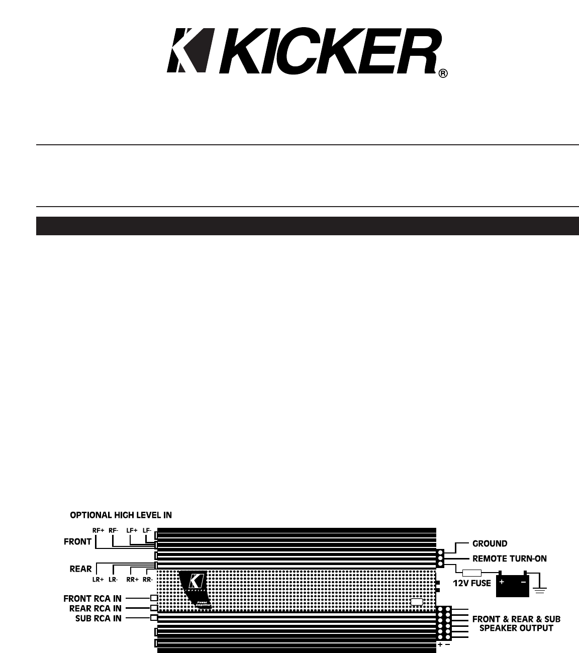
The preferred method of bringing input signal in to the amplifier is with RCA cables from a quality tape or CD
player. A high (speaker) level input signal may also be used if your factory deck or aftermarket source does not
have low level RCA jacks. It is not recommended to mix high and low level inputs. Engine noise in the system will
probably result.
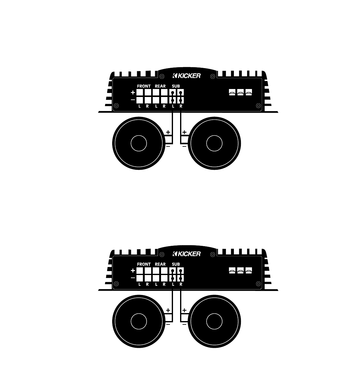
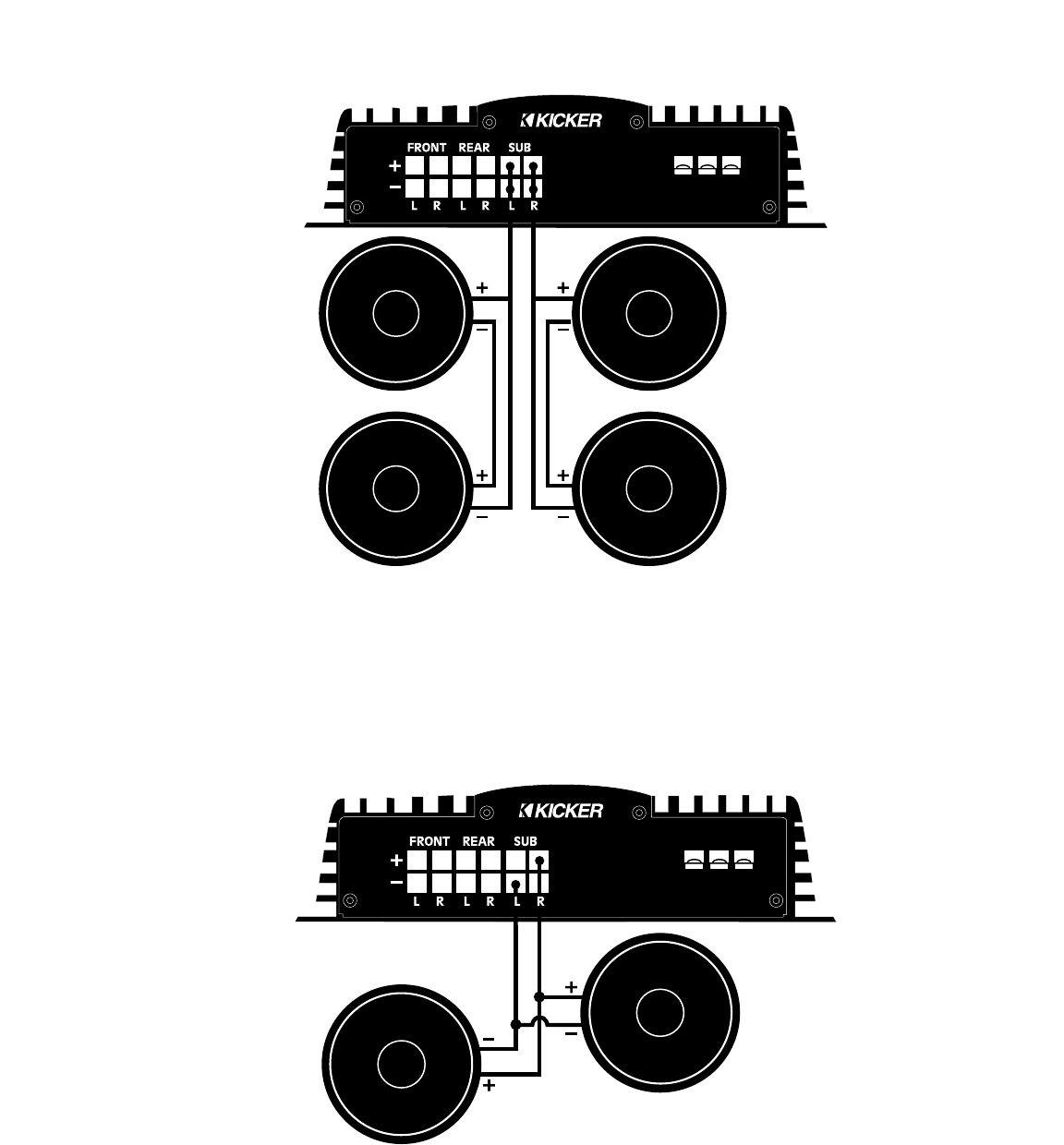
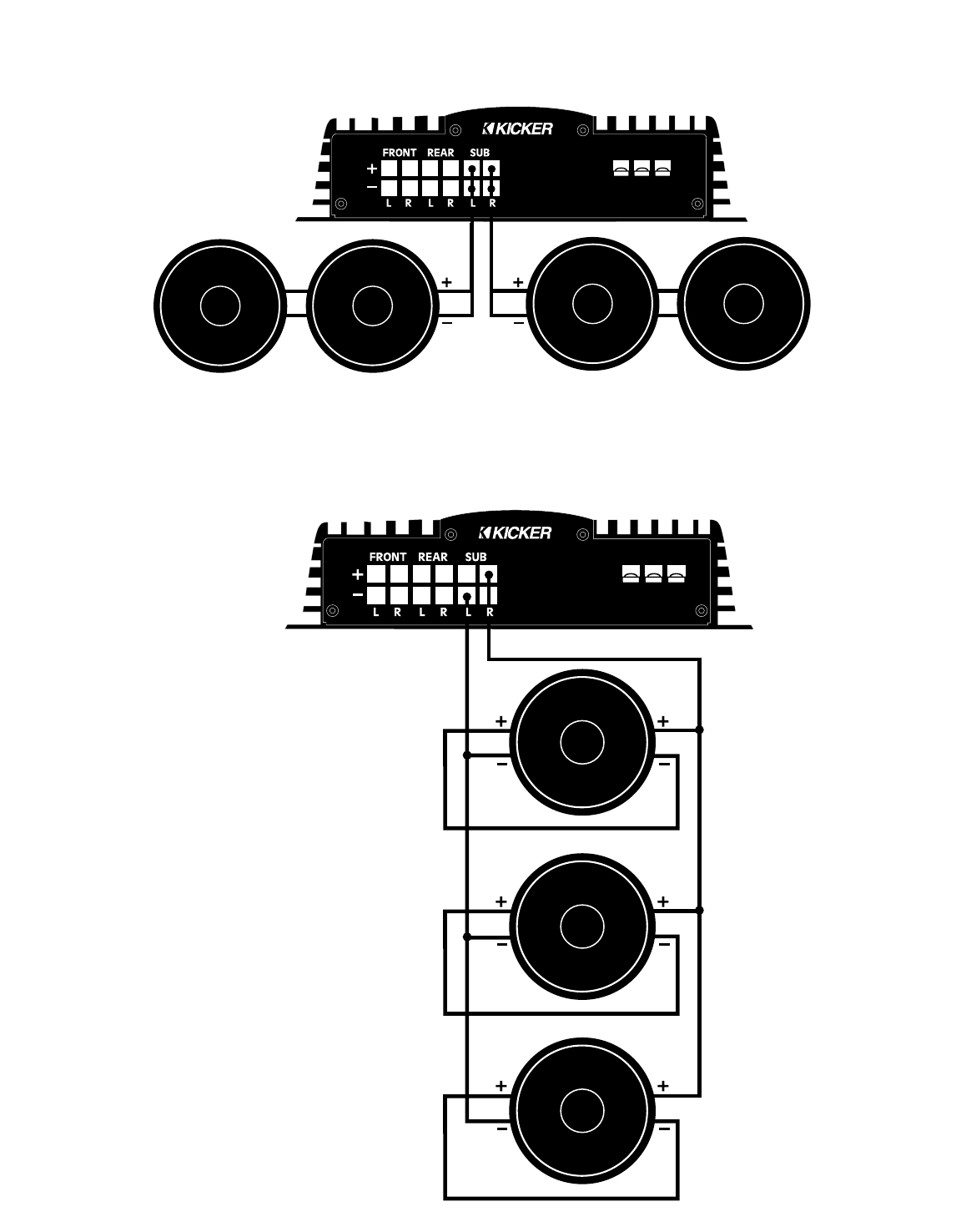
ome of the system possibilities are shown in the System Diagrams section of this manual.
When working with power connections always hook up the ground wire first and disconnect the ground wire last.
Never make any wiring changes with the amplifier powered up.
The chassis mounted fuse(s) are in place to protect the circuitry of the amplifier in the event of major trouble. An
in-line fuse must be installed within 18 inches of the battery to protect the power wire used to supply current to
the amplifier. For the Kicker Impulse IX406 amplifier a fuse value of 60A and 8 gauge power wire are recommended.
If the power wire is longer than 10 feet, it is recommended that the wire size be 4 gauge to reduce losses.
Any time that a power wire goes through a metal panel such as the firewall, or if there is any chance of abrasion,
it is necessary to use a grommet or other suitable form of protection to avoid shorts.
The ground wire should be at least 8 gauge, as short as possible and attached to the body of the vehicle. The
ground point must be free from paint and corrosion.
Mounting the IMPULSE Amplifier
After determining an appropriate mounting
location which provides good air circulation and
access to the end panel controls, use the supplied
screws and washers to firmly mount the amplifi-
er.The amplifier chassis can be used as a template
for the screw locations. Check to make sure that
the mounting screws will not damage any compo-
nents on the back side of the chosen mounting
surface.
If a vertical mounting surface is chosen, we rec-
ommend that the heatsink fins run vertically as
shown for improved cooling.
EXPLANATION OF INPUT OPTIONS FOR THE IMPULSE IX406
The IX406 amplifier has five different options for hookup to your source unit.
1. One pair of RCA cables.
2. Two pairs of RCA cables.
3. Three pairs of RCA cables.
4. One stereo pair of high level inputs.
5. Two stereo pairs of high level inputs.
Combinations of high and low level inputs are not recommended
The Parallel input selector switch allows you to select one or two inputs (low level or high). The sub channels get
their signal from the front and rear inputs, or from separate RCA jacks, determined by the position of the Sub
Channel input switch.
Input Option 1: Using One Pair of RCA Cables
With the Parallel input selector switch in “ON” position, and the Sub input switch in the “F+R” position, all six
channels receive input from the front input RCAs.This configuration gives output on all six channels with only one
pair of inputs. There is no fader capability.
Input Option 2: Using Two Pairs of RCA Cables
With the Parallel input selector switch in the “OFF” position, and the Sub input switch in the “F+R” position, the
fader capabilities are enabled and the sub channels get signals from both front and rear inputs.
Input Option 3: Using Three Pairs of RCA Cables
If the source unit has a separate sub output or if using an external crossover use this configuration. With the
Parallel input selector in the “OFF” position and RCAs plugged into the sub inputs, you have six inputs and six out-
puts, all separate.
Input Option 4: Using a Stereo Pair of High Level Inputs
With the Parallel input selector switch in “ON” position, and the Sub input switch in the “F+R” position, all six chan-
nels receive input from the front high level inputs. There is no fader capability.
Input Option 5: Using Two Stereo Pairs of High Level Inputs
With the Parallel input selector switch in the “OFF” position, and the Sub input switch in the “F+R” position, fader
capability is enabled and the sub channels get signal from both front and rear inputs.
Basic Sub Options for the IMPULSE Six-Channel Amplifier
Using One 4 or 8 Ohm Subwoofer
Using Two 2 or 4 Ohm Subwoofers
Using Four 2 Ohm Subwoofers
Using Two 8 Ohm Subwoofers
Basic Systems for the IMPULSE Six-Channel Amplifier
Front & Rear Speakers with Stereo Subwoofers*
Front & Rear Speakers with Bridged Mono Subwoofer(s)*
*Front & Rear crossovers set to 70 or 110Hz highpass.
Sub crossover set to 70 or 110Hz lowpass.
Using Four 4 or 8 Ohm Subwoofers
Using Three 6 Ohm DVC Subwoofers
Adjustments and Controls
Setting Gain Control
The gain control is provided for level matching purposes. The control does not give the amplifier any more
power by turning it up. Its purpose is to adjust the sensitivity of the amplifier in relation to the output level provid-
ed by the source.
Start with the amp gains set to minimum by turning the controls counter-clockwise. Turn the source level up
until distortion is barely audible. Then turn the source down slightly. This will typically be at about 85 to 95% of full
volume. Raise the front amplifier gain control until distortion is just audible in the front speakers. Now the deck is
matched to the front amplifier channels. Turn the source down to a realistic listening level.
Turn the rear amplifier gain control up until the desired front/rear balance is achieved.
Turn the sub amplifier gain control up to provide the bass level desired.
Note: As the KICKEQ controls are turned up to provide additional bass or treble, the overall signal goes up. It may
be necessary to readjust the gain controls if the KICKEQ controls are turned up very much.
Setting KICKEQ™ Controls
The Bass and Treble controls on your Impulse Amplifier are provided to help tune your system for ideal sound
quality. After the system is installed and the vehicle is put back together, do a listening test with music that is typi-
cal of the type you normally listen to.
Initially set the tone controls on the source unit to flat and turn the KICKEQ™ controls fully counter-clockwise.
Depending on your personal taste and the speakers used in the system, you may want to increase the high or low
frequencies by turning the KICKEQ™ controls clockwise. Remember that once the vehicle is in motion there will be
an apparent loss of bass due to the masking effect of road noise. Do not attempt to make adjustments while the
vehicle is in motion. It is safer to pull off the road to make changes.
Never change the crossover settings while the amplifier is on. A loud pop will result which could destroy speakers
or cause hearing loss.
Troubleshooting
The LED mounted on the end panel of the amplifier lights up in two different colors depending on the condition
of the amplifier. Green indicates that the amplifier is turned on and no trouble exists. When it turns red this indi-
cates that the protection circuit has been engaged. The LED on the top of the amplifier chassis indicates that the
amplifier is on. When the protection circuit is engaged, this LED turns off.
Green power indicator off, no output:
• With Volt Ohm Meter (VOM) check:
1. +12v power terminal
2. Ground terminal
3. Remote turn-on lead
Green power indicator on, no output:
• Check RCA and connections
• Test speaker outputs with known good speaker
• Check function of source unit
• With VOM in AC volts position check RCA for signal
No output from one channel:
• Check RCA and speaker connections for that channel
• Swap RCA connections from left to right
• Swap speaker connections between channels
Red LED protection indicator is lit and there is no output:
Case 1: Amp is very hot
• Thermal protection is engaged. Check for proper impedance at speaker terminals.
Also check location of amplifier to ensure proper air flow around heatsink.
Case 2: Output resumes momentarily when system is turned off and back on.
• Short circuit protection is engaged. With VOM check for short between speaker positive and negative,
and between speaker terminals and ground.
Alternator noise (a whining that varies with engine RPM)
• Make sure that the ground for the source is as short as possible and connected to bare chassis metal.
The stock radio ground may not be sufficient.
• Check RCA cable routing and condition. Keep RCA cables away from all power wires.
Specifications
Model RMS Power (watts/channel) RMS Power (watts/channel) RMS Power (watts) Dimensions (inches)
@ 12.5V, 4 stereo, 0.085% THD, @ 12.5V, 2 stereo,0.2% THD, @ 12.5V, 4 bridged mono, HxWxL
all channels driven all channels driven 0.2% THD
IX406 40 x 6 55 x 4 115 x 3 2.5x9.5x18.9
Dynamic Power (watts/channel) Dynamic Power (watts/channel) Dynamic Power (watts) Dimensions (mm)
@ 14.4V, 4 stereo, 0.085% THD, @ 14.4V, 2 stereo, 0.2% THD, @ 14.4V, 4 bridged mono, HxWxL
all channels driven all channels driven 0.2% THD
IX406 55 x 6 75 x 6 150 x 3 63x241x482
Frequency Response 20Hz-20kHz ±0.5dB
Input Sensitivity High level 1V-10V
Low level 150mV-3.0V
Signal-to-Noise Ratio >95dB, a-weighted, re: rated power
Active Electronic Crossover 18dB/octave, selectable @ 70Hz or 110 Hz;
KICKEQ™ Bass Boost Variable to +18dB, centered @ 40Hz
KICKEQ™ Treble Boost Variable to +12dB, centered @ 18kHz
11

Hulp nodig? Stel uw vraag in het forum

Spelregels

Misbruik melden

Gebruikershandleiding.com neemt misbruik van zijn services uitermate serieus. U kunt hieronder aangeven waarom deze vraag ongepast is. Wij controleren de vraag en zonodig wordt deze verwijderd.

Product:

Bijvoorbeeld antisemitische inhoud, racistische inhoud, of materiaal dat gewelddadige fysieke handelingen tot gevolg kan hebben.

Bijvoorbeeld een creditcardnummer, een persoonlijk identificatienummer, of een geheim adres. E-mailadressen en volledige namen worden niet als privégegevens beschouwd.

Spelregels forum

Om tot zinvolle vragen te komen hanteren wij de volgende spelregels:

Belangrijk! Als er een antwoord wordt gegeven op uw vraag, dan is het voor de gever van het antwoord nuttig om te weten als u er wel (of niet) mee geholpen bent! Wij vragen u dus ook te reageren op een antwoord.

Belangrijk! Antwoorden worden ook per e-mail naar abonnees gestuurd. Laat uw emailadres achter op deze site, zodat u op de hoogte blijft. U krijgt dan ook andere vragen en antwoorden te zien.

Abonneren

Abonneer u voor het ontvangen van emails voor uw Kicker ix 406 impulse bij:


U ontvangt een email met instructies om u voor één of beide opties in te schrijven.


Ontvang uw handleiding per email

Vul uw emailadres in en ontvang de handleiding van Kicker ix 406 impulse in de taal/talen: Engels als bijlage per email.

De handleiding is 0,99 mb groot.


U ontvangt de handleiding per email binnen enkele minuten. Als u geen email heeft ontvangen, dan heeft u waarschijnlijk een verkeerd emailadres ingevuld of is uw mailbox te vol. Daarnaast kan het zijn dat uw internetprovider een maximum heeft aan de grootte per email. Omdat hier een handleiding wordt meegestuurd, kan het voorkomen dat de email groter is dan toegestaan bij uw provider.

Stel vragen via chat aan uw handleiding

Stel uw vraag over deze PDF

Uw handleiding is per email verstuurd. Controleer uw email

Als u niet binnen een kwartier uw email met handleiding ontvangen heeft, kan het zijn dat u een verkeerd emailadres heeft ingevuld of dat uw emailprovider een maximum grootte per email heeft ingesteld die kleiner is dan de grootte van de handleiding.

Er is een email naar u verstuurd om uw inschrijving definitief te maken.

Controleer uw email en volg de aanwijzingen op om uw inschrijving definitief te maken

U heeft geen emailadres opgegeven

Als u de handleiding per email wilt ontvangen, vul dan een geldig emailadres in.

Uw vraag is op deze pagina toegevoegd

Wilt u een email ontvangen bij een antwoord en/of nieuwe vragen? Vul dan hier uw emailadres in.


Info