686277
15
Verklein
Vergroot
Pagina terug
1/194
Pagina verder
X8 MIG Welder
OPERATING MANUAL
ii
Contents
1 Read first.................................................................................................................... 4
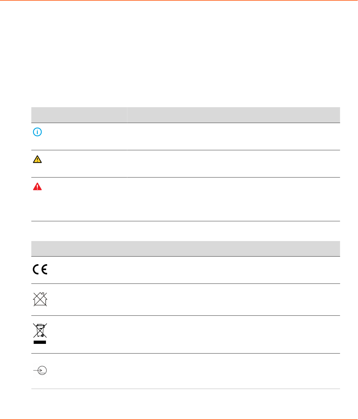
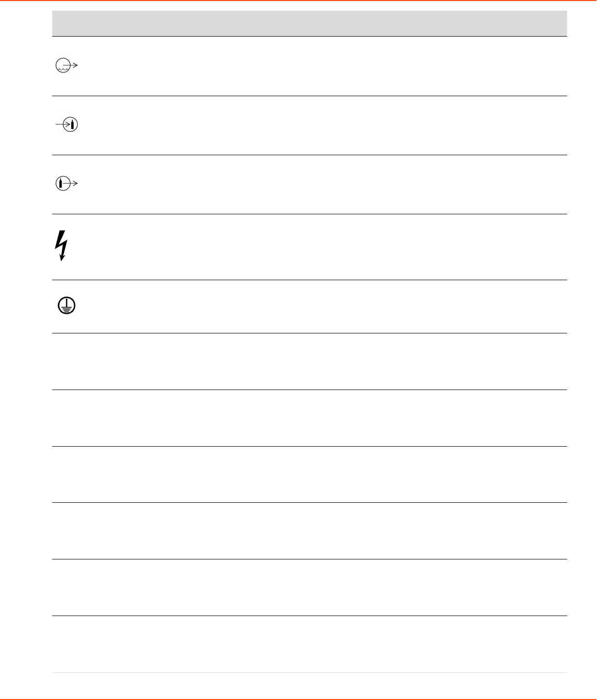
1.1 Symbols..................................................................................................................................................................................... 4
2 X8 MIG Welder.......................................................................................................... 8
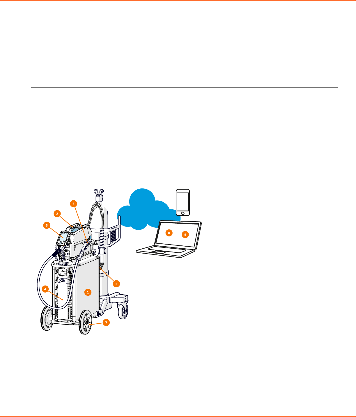
2.1 System introduction............................................................................................................................................................. 8
2.1.1 Introduction to WeldEye for welding procedure and qualification management....................... 9
2.2 System structure..................................................................................................................................................................10
2.2.1 X8 Power Source.................................................................................................................................................11
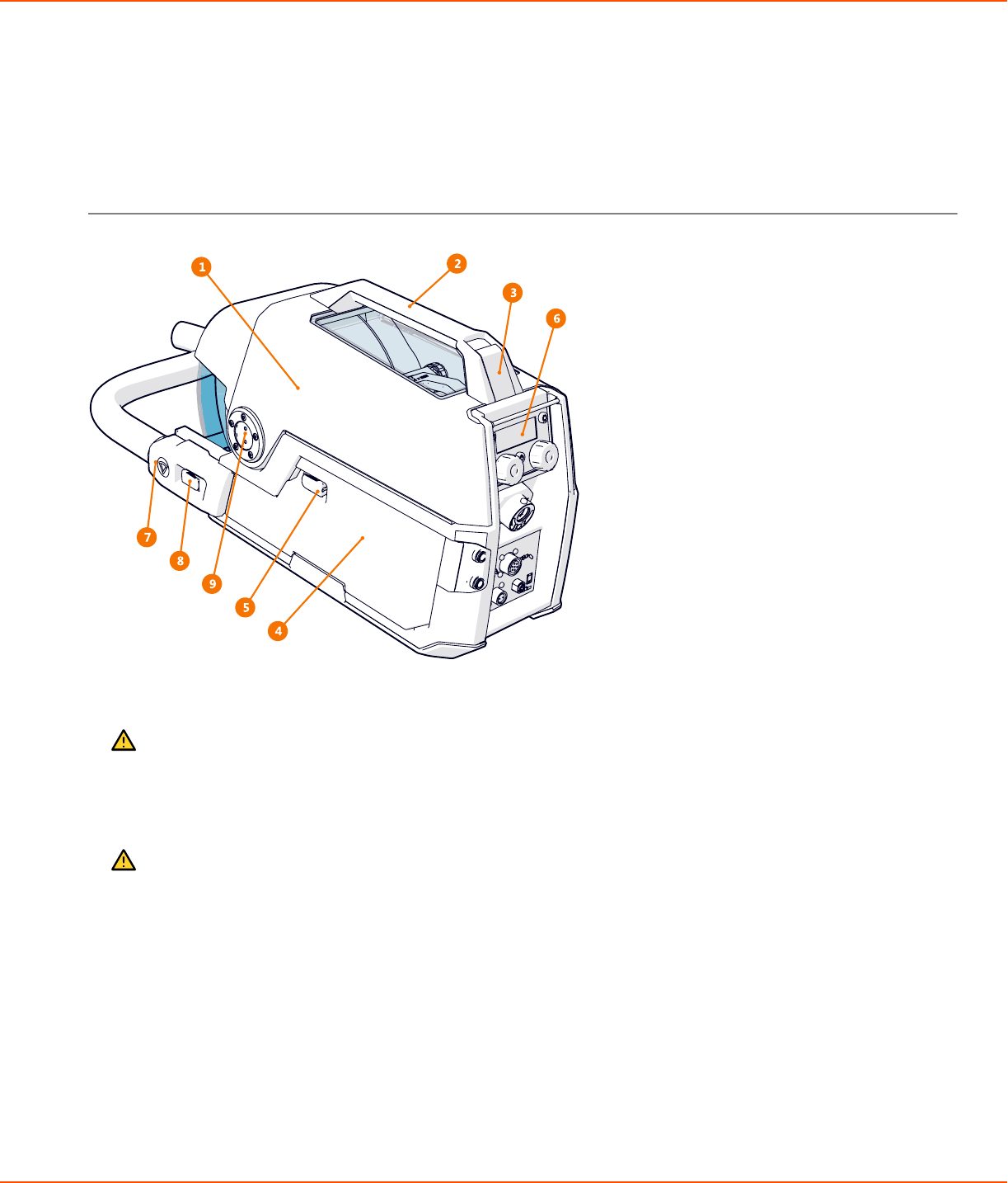
2.2.2 X8 Wire Feeder....................................................................................................................................................15
2.2.3 X8 MIG Guns........................................................................................................................................................ 20
2.2.4 Control Pad............................................................................................................................................................22
2.3 Installation..............................................................................................................................................................................25
2.3.1 Before installation...............................................................................................................................................25
2.3.2 Power Source installation................................................................................................................................26
2.3.3 Wire Feeder installation...................................................................................................................................34
2.3.4 Cables installation...............................................................................................................................................50
2.3.5 Control Pad installation....................................................................................................................................55
2.3.6 Welding gun installation..................................................................................................................................59
2.3.7 Lifting X8 MIG Welder......................................................................................................................................78
2.3.8 Purchasing and managing welding software..........................................................................................79
2.3.9 Optional accessories..........................................................................................................................................79
2.4 Operation............................................................................................................................................................................... 84
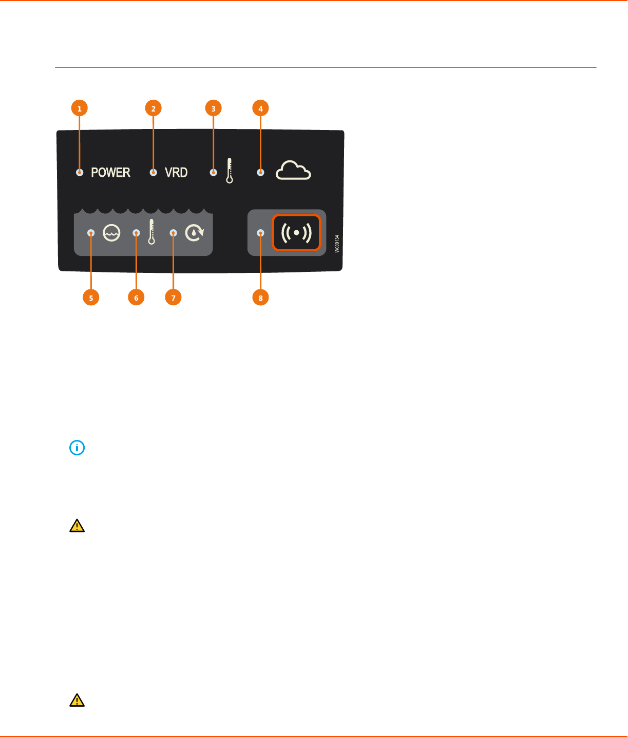
2.4.1 X8 MIG Welder control devices....................................................................................................................84
2.4.2 Preparing welding system for use.............................................................................................................101
2.4.3 How to use welding system........................................................................................................................110
2.5 Troubleshooting................................................................................................................................................................ 166
2.5.1 Error codes..........................................................................................................................................................170
2.6 Maintenance....................................................................................................................................................................... 170
2.6.1 Daily maintenance............................................................................................................................................171
2.6.2 Periodic maintenance of power source and wire feeder..................................................................173
2.6.3 Service workshops........................................................................................................................................... 174
2.7 Technical data.................................................................................................................................................................... 174
2.7.1 X8 Power Source 400 A / 400AMV....................................................................................................... 174
2.7.2 X8 Power Source 500 A / 500AMV....................................................................................................... 176
2.7.3 X8 Power Source 600 A / 600AMV....................................................................................................... 178
2.7.4 X8 Cooler.............................................................................................................................................................180
2.7.5 X8 Wire Feeder..................................................................................................................................................180
2.7.6 X8 Control Pad..................................................................................................................................................181
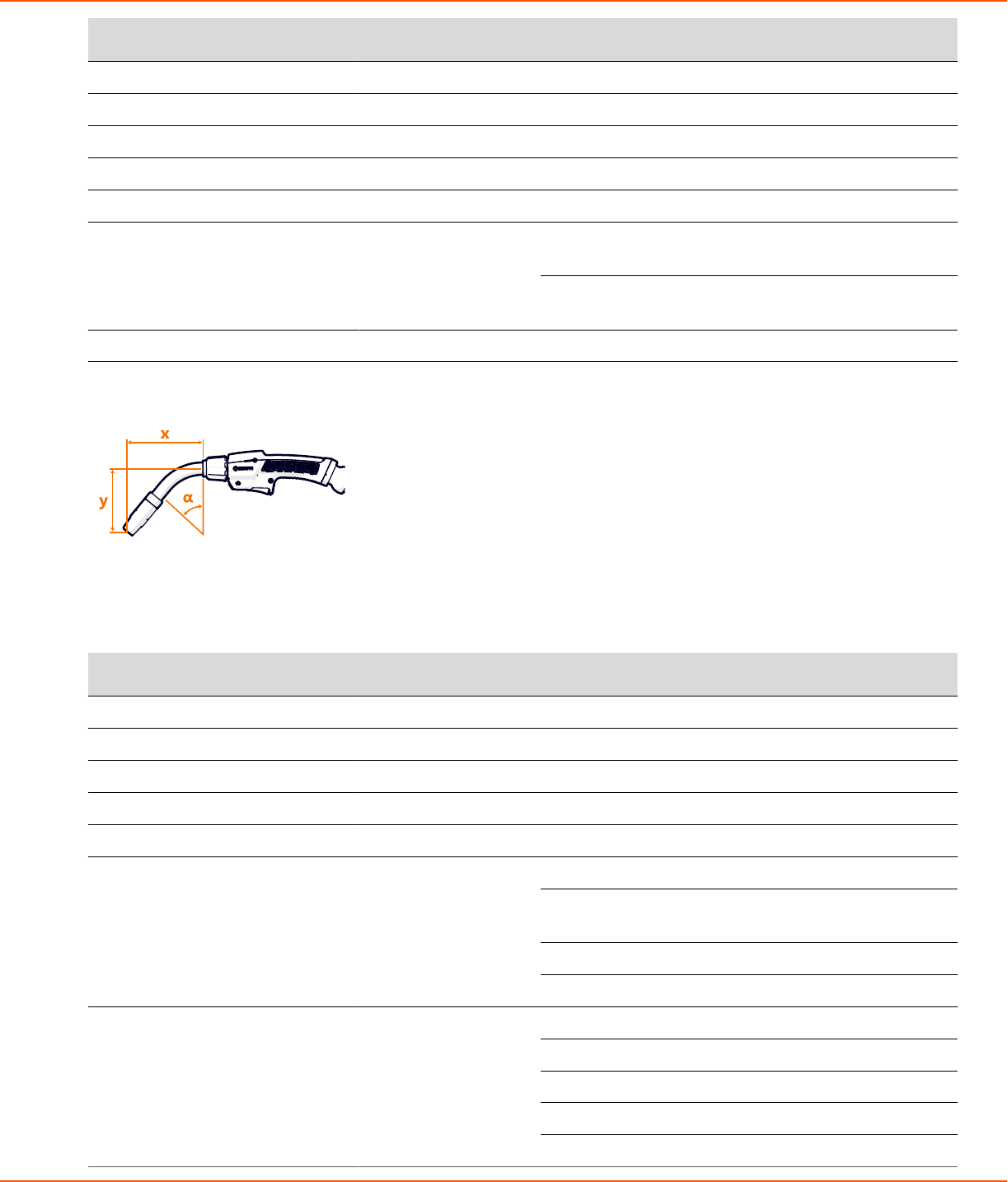
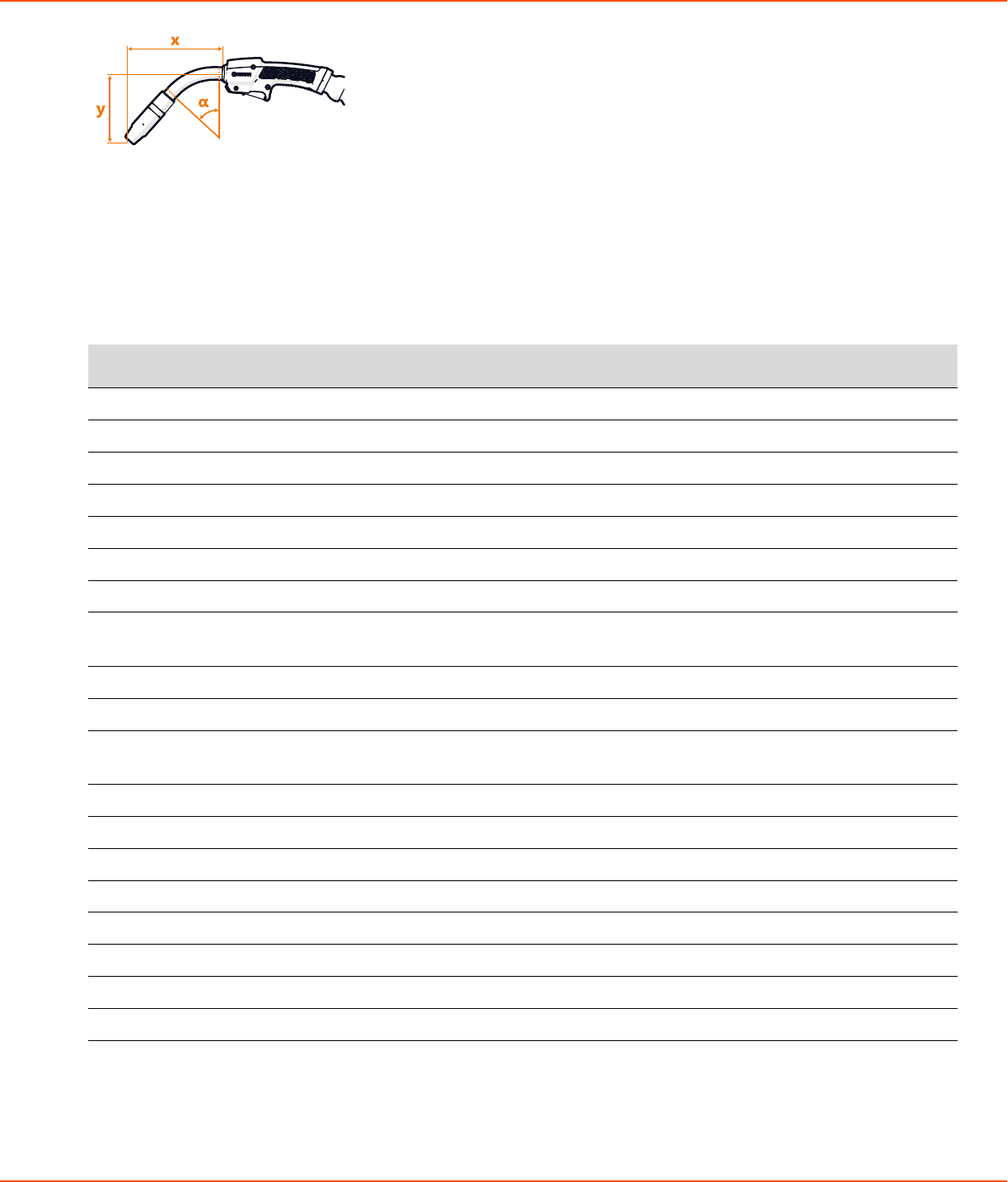
2.7.7 X8 MIG Gun 200-g..........................................................................................................................................182
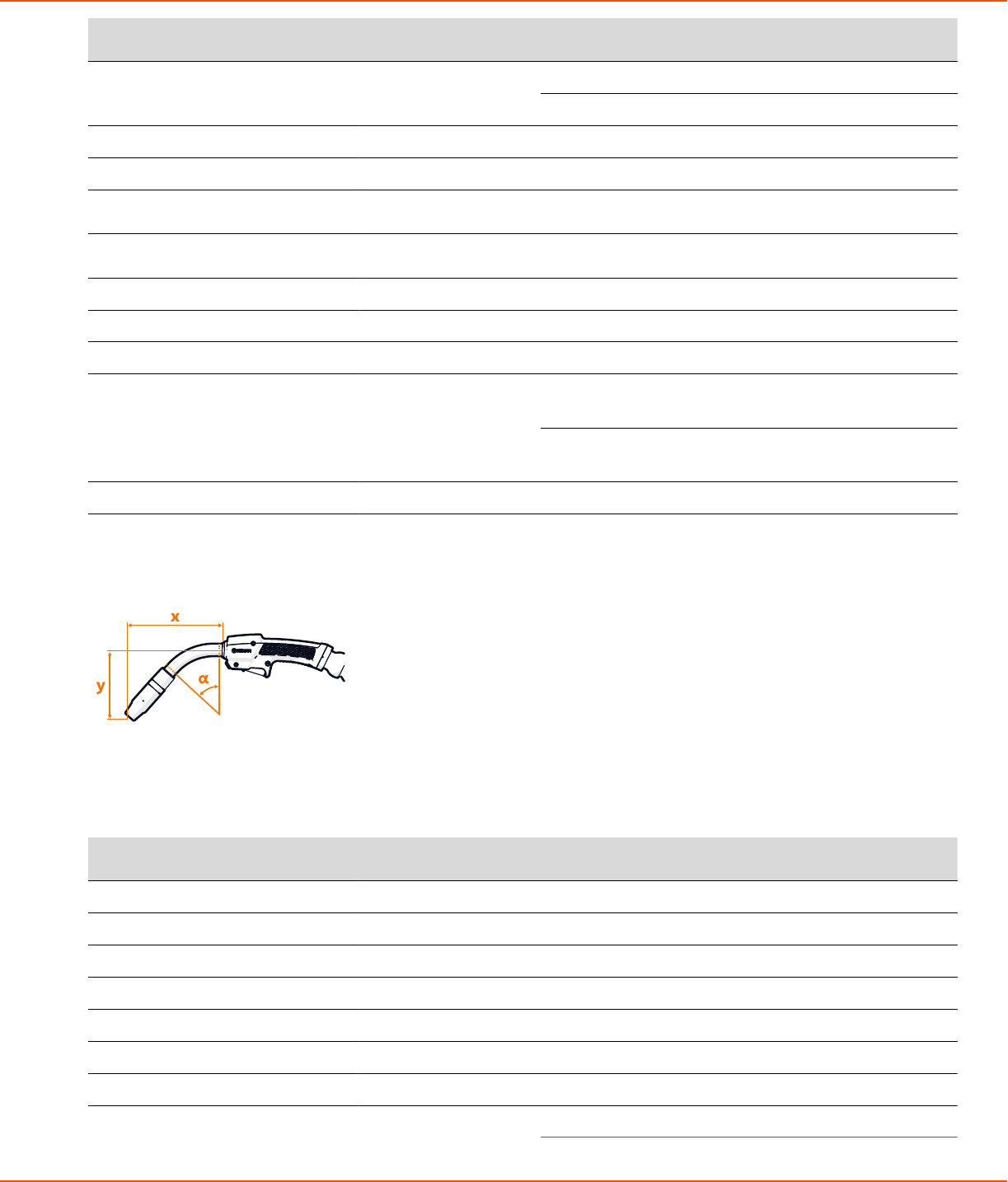
2.7.8 X8 MIG Gun 300-g..........................................................................................................................................183
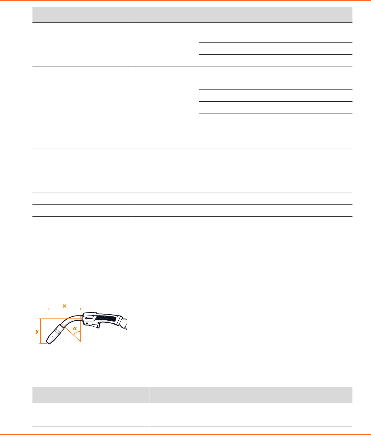
2.7.9 X8 MIG Gun 400-g..........................................................................................................................................184
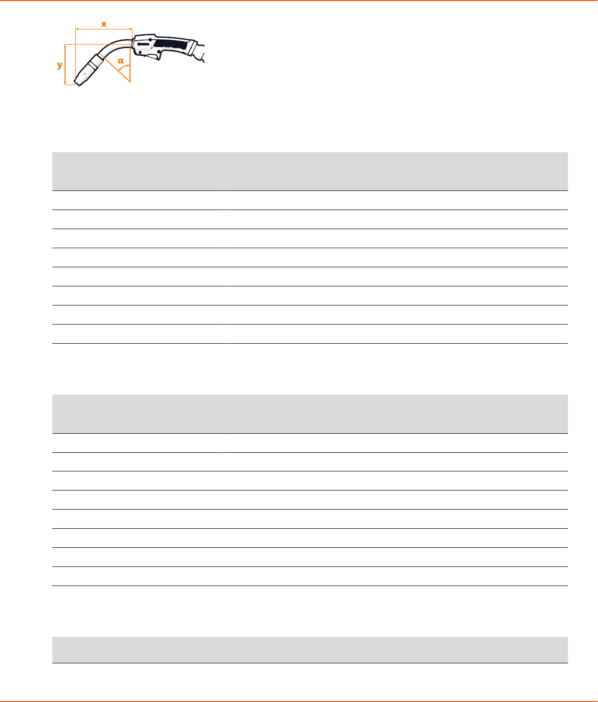
2.7.10 X8 MIG Gun 420-w.......................................................................................................................................185
2.7.11 X8 MIG Gun 520-w.......................................................................................................................................186
2.7.12 X8 MIG Gun 600-w.......................................................................................................................................187
2.7.13 X8 MIG Gun WS 420-w...............................................................................................................................189
iii
2.8 Ordering codes..................................................................................................................................................................190
2.9 Disposal of unit.................................................................................................................................................................193
X8 MIG WELDER 1.1 Symbols
1 Read first
Kemppi takes special care in informing its customers about the safety of our products. We also mind the
environment and aspire to disposing of our products according to specified European Directives.
1.1 Symbols
Items in the manual that require particular attention, to minimize damage and personal harm, are indicated
with a three-level notification and warning system.
Convention Used for
Note:
Note text here.
Gives the user a piece of information of particular importance.
Caution:
Caution text here.
Describes a situation that may result in damage to the equipment or
system.
Warning:
Warning text here.
Describes a potentially dangerous situation that may result in personal
damage or fatal injury.
Kemppi symbols
Table 1: Kemppi symbols used in this documentation
Symbol Description
CE mark
EMC Class A
This symbol indicates that the waste of electrical and electronic equipment
must not be disposed as unsorted municipal waste and must be collected
separately. Contact an authorized representative of the manufacturer for
information concerning the decommissioning of your equipment.
Coolant input
OPERATING MANUAL | EN 4
©
KEMPPI | 2018-09-28
X8 MIG WELDER 1.1 Symbols
Symbol Description
Coolant output
Gas input
Gas output
High voltage
Protective earth
#
1-MIG
'
DPulse MIG
8
Carbon arc gouging
!
MIG
5
MMA
%
Pulse MIG
OPERATING MANUAL | EN 5
©
KEMPPI | 2018-09-28
X8 MIG WELDER 1.1 Symbols
Symbol Description
DProcess
,
WiseRoot+
*
WiseThin+
+
WiseFusion
E
WiseSteel
ŕ
WisePenetration+
P
Creep Start
S
Hot Start
R
Upslope
T
Crater Fill with Downslope
U
Crater Fill with Downlevel
OPERATING MANUAL | EN 6
©
KEMPPI | 2018-09-28
X8 MIG WELDER 1.1 Symbols
Symbol Description
Ö
2T
Õ
4T
W
WP Switch
Ɔ
Touch Sense Ignition
O
User manual
OPERATING MANUAL | EN 7
©
KEMPPI | 2018-09-28
X8 MIG WELDER 2.1 System introduction
2 X8 MIG Welder
These instructions describe the use of Kemppi's X8 MIG Welder, the top-class welding system for demanding
industrial use. The system consists of a power source, wire feeder, welding gun, Control Pad and various
welding software components and connectivity to Kemppi cloud services. Read the instructions through
carefully.
Disclaimer
While every effort has been made to ensure that the information contained in this guide is accurate and
complete, no liability can be accepted for any errors or omissions. Kemppi reserves the right to change the
specification of the product described at any time without prior notice. Do not copy, record, reproduce or
transmit the contents of this guide without prior permission from Kemppi.
2.1 System introduction
X8 MIG Welder is a multi-process welding equipment intended for demanding professional use in general or
heavy fabrication. The welding system is suitable for various MIG/MAG processes (MIG, 1-MIG, Pulse, DPulse,
WiseRoot+, WiseThin+ ) as well as MMA welding and gouging, cladding and brazing.
1. X8 Power Source 400/500/600
Includes all the software, welding programs and memory channels for the welding system
Connects to one or two X8 Wire Feeders
2. X8 Wire Feeder
Operates with several wire spool types (some of which require an adapter)
Connects to an external wire drum
OPERATING MANUAL | EN 8
©
KEMPPI | 2018-09-28
X8 MIG WELDER 2.1 System introduction
Contains a control panel for basic adjustment of welding parameters, memory channels and settings
3. X8 MIG Gun 200/300/400-g, 420/520/600-w, X8 MIG Gun WS 420-w
Connects to the wire feeder with Kemppi Gun Adapter
Gas-cooled models feature a rotating, changeable neck
Remote control for selecting memory channels and adjusting settings (optional)
Ergonomic pistol grip handle
4. X8 Cooler (optional)
Optionally included in the power source delivery
Can also be purchased separately
Essential for welding with a current over 400 A
5. Control Pad
Wireless remote interface for operating X8 MIG Welder
6. Interconnection Cable 70/95-w/-g (several options)
Bundle of cables connecting the wire feeder to the power source
Transfers the welding current, control signals, shielding gas and coolant from the power source to the
wire feeder
7. X8 Wheel Set (several options)
The wheel set is included in the power source delivery
The gas cylinder cart is optionally included in the power source delivery
8. My Fleet web service
Cloud-based service for viewing and managing various information about your X8 MIG Welder
Provides manufacturer's validation certificate
9. WeldEye (optional)
Cloud-based service for creating and managing digital WPS documents and other welding-related
information
In addition:
Several accessories (optional)
Several welding software products (optional)
2.1.1 Introduction to WeldEye for welding procedure and qualification
management
Welding procedure and qualification management
WeldEye for Welding procedure and qualification management is a cloud-based tool for creating, managing
and storing various welding-related documents and qualification certificates. WeldEye is an end-to-end
solution for handling pWPS, WPQR and WPS documents as well as welder qualification certificates. The
software contains procedure and certificate templates to match all major welding standards. Together with its
integrated drawing tool, WeldEye is swift and easy to use.
The software enables you to keep track of qualification certificates and their expiration dates, and to easily
extend their validity. Revision history helps you track the changes made to the documents. With a flexible
search functionality, you can easily find the welding procedures, personnel, and certificates you need. You
OPERATING MANUAL | EN 9
©
KEMPPI | 2018-09-28
X8 MIG WELDER 2.2 System structure
can print out documents or, for example, a list of welders with a certain qualification certificate. Attachments
can be added to any document.
Discover WeldEye – universal welding management software
WeldEye is your primary tool and storage space for keeping your welding-related documents in order.
There is even more to WeldEye than welding document management. WeldEye is a universal solution for
managing welding production. Fitting any size and type of organization that performs welding within the
requirements of international welding standards like ISO, ASME and AWS, WeldEye provides control in all
processes - including welding procedures, welder and inspector qualifications, documentation, reporting and
administration. Most importantly, you get 100% traceability for every weld you ever make.
WeldEye's modular structure is based on various useful functions that serve the needs of wide-ranging
industries and welding-related tasks:
Welding procedures
Includes the digital library and management of pWPS, WPQR and WPS templates according to the most
important welding standards.
Personnel and qualifications
Includes the management and renewal processes of all personnel - welders and inspectors - qualification
certificates.
Quality management
Includes quality verification functionalities with digital WPS and qualification compliance control against
automatically collected digital welding data.
Welding management
Includes document register functionalities and features for comprehensive welding project
documentation and management.
For more information on the full system and other modules, see www.weldeye.com.
2.2 System structure
The parts of X8 MIG Welder are in close co-operation with each other. The information transfer is efficient
and quick, and the different functions, for example, the use of displays, follow the same principles.
Caution:
Do not modify the welding equipment in any way, except for the changes and adjustments covered
in the manufacturers instructions.
OPERATING MANUAL | EN 10
©
KEMPPI | 2018-09-28
X8 MIG WELDER 2.2 System structure
Figure 1: A chart of the connections between the different parts of X8 MIG Welder
2.2.1 X8 Power Source
This section describes the structure of X8 Power Source.
Front
5
7
1
6
42 3
1. Indicator panel
2. Transportation handle
OPERATING MANUAL | EN 11
©
KEMPPI | 2018-09-28
X8 MIG WELDER 2.2 System structure
3. USB connector
Connect a USB memory stick to upload the welding procedures (WPS) or Wise features to the power
source or update firmware if a wireless connection is unavailable.
4. Control Pad connector
Connect Control Pad to the power source with a cable to charge its battery or to use it in wired mode.
5. Front panel
6. Front panel latch
Pull to open the front panel and reveal the coolant container.
7. Coolant circulation button
Press to pump the coolant through the system.
Rear
6
2
3
3
2
4
4
8
5
5
9
7
10
1
11
12
1. Transportation handle
2. Welding current cable connectors (positive pole)
3. Earth return cable connectors (negative pole)
4. Measurement cable connectors
Connectors for wire feeder 1 on the left, wire feeder 2 on the right side of the power source.
5. Control cable connectors
Connectors for wire feeder 1 on the left, wire feeder 2 on the right side of the power source.
6. Ethernet connector
7. Power switch
8. Coolant outlet hose connector
9. Coolant inlet hose connector
10. Rear panel
11. Mains cable
OPERATING MANUAL | EN 12
©
KEMPPI | 2018-09-28
X8 MIG WELDER 2.2 System structure
12. Strain relief holder
Indicator panel
1. Power indicator
The LED is green when the unit is on.
2. Voltage Reduction Device (VRD) indicator
The LED is green when VRD is switched on and the no-load voltage is under 35 V.
The LED blinks red when VRD is switched on and the no-load voltage is above 35 V.
The LED is off when VRD is switched off or during welding.
Note:
VRD is in use with MMA and Gouging modes only.
3. Overheat indicator
The LED is yellow when the unit is overheating.
Caution:
If the power source overheats, a thermal cutoff switches the unit off and does not allow it to be
used until it has cooled down.
4. Kemppi cloud connection
The LED is blue when the wire feeder or power source is connected to Kemppi cloud services.
The LED blinks blue when the wire feeder or power source is connecting to Kemppi cloud services.
5. Coolant level warning
The LED is yellow when the coolant level is too low.
6. Coolant temperature warning
The LED is yellow when the cooler is overheating.
Caution:
OPERATING MANUAL | EN 13
©
KEMPPI | 2018-09-28
X8 MIG WELDER 2.2 System structure
If the coolant liquid overheats, a thermal cutoff switches the welding system off and does not
allow it to be used until the coolant liquid has cooled down.
7. Coolant circulation warning
The LED is green when the coolant circulation is working normally.
The LED is red when there is a problem in the coolant circulation.
The LED blinks green and red in turns when the circulation of the coolant liquid has been obstructed too
long.
Caution:
If the circulation of the coolant liquid is obstructed, a thermal cutoff switches the welding system
off. Check and fix the error before using the welding system again.
If the error was caused in an unsuccessful filling of the cooler, refill the cooler. In other cases, the
error disappears automatically in 30 seconds.
8. Wireless pairing button
To pair the wire feeder or power source with Control Pad, press the button. If the power source is
connected to wire feeder(s), the wire feeder(s) pairs with Control Pad. If the power source is not
connected to a wire feeder, the power source pairs with Control Pad.
The LED is blue when the wire feeder or power source is wirelessly connected to Control Pad.
The LED blinks blue when the wire feeder or power source is pairing with Control Pad.
Interconnection cable
7
1
4
2
3
65
1. Shielding gas hose
2. Coolant inlet hose
3. Coolant outlet hose
4. Welding current cable
5. Control cable
OPERATING MANUAL | EN 14
©
KEMPPI | 2018-09-28
X8 MIG WELDER 2.2 System structure
6. Measurement cable
7. Strain relief pin
2.2.2 X8 Wire Feeder
This section describes the structure of X8 Wire Feeder.
Main parts
1. Top cover
Caution:
Keep the wire feeder top cover closed during welding to reduce the risk of injury or an electric
shock. Keep the top cover closed also at other times to keep the wire feeder insides clean.
2. Handle
Caution:
The handle is only intended for short distance manual carrying. Use Wire Feeder Hanger for
Boom for lifting or hanging the wire feeder.
3. Top cover latch
4. Cable cabinet door
5. Cable cabinet latch
6. Control panel
7. Strain relief
8. Strain relief latch
9. Gun holder mount
OPERATING MANUAL | EN 15
©
KEMPPI | 2018-09-28
X8 MIG WELDER 2.2 System structure
15
12
13
14
1011
Figure 2: The warning sticker inside the wire feeder
10. Wire spool
11. Wire spool locking cover
12. Feed rolls
13. Pressure handle
14. Wire guide
15. Inside control buttons
OPERATING MANUAL | EN 16
©
KEMPPI | 2018-09-28
X8 MIG WELDER 2.2 System structure
Control panel
The control panel on the front of the wire feeder enables easy control of the wire feeder's basic features.
Although Control Pad is the main control of the welding system, you can also use the wire feeder control
panel or the welding gun remote control.
5
6
2
1
4
3
5
6
2
1
4
3
The wire feeder control panel parts are:
1. Locking button
Press and hold for 2 seconds to lock or release the display and buttons.
2. Channel button
The button lights up blue, when the view is activated.
OPERATING MANUAL | EN 17
©
KEMPPI | 2018-09-28
X8 MIG WELDER 2.2 System structure
3. Settings button
The button lights up orange, when the view is activated.
4. Left control knob
5. Right control knob
6. Left and right button
For more information on the use and features of the control panel, see Wire feeder views on page 96.
Control buttons on the inside
The wire feeder has control buttons inside the wire cabinet.
1. Wire retract button
Drive the filler wire backward with arc off.
2. Gas test button
Test the shielding gas flow, or flush out the remainder of the previous gas.
3. Wire inch button
Drive the filler wire forward with arc off.
Interconnection cable connectors
OPERATING MANUAL | EN 18
©
KEMPPI | 2018-09-28
X8 MIG WELDER 2.2 System structure
1. Welding current
Supplies current from the power source to the wire feeder.
2. Shielding gas
Supplies shielding gas to the welding gun.
3. Measurement
Supplies the welding parameters measured during welding.
4. Control
Supplies data and operating voltage to the wire feeder.
5. Coolant outlet and inlet
Circulates coolant to and from the welding gun.
For information on the installation of the cables, see Cables installation on page 50.
External component connectors
1. Kemppi Gun Adapter
Connects to the welding gun.
Note:
The wire feeder is supplied with Kemppi Gun Adapter.
2. Subfeeder
Provides control to optional SuperSnake subfeeder or a motorized welding gun.
3. Remote control
Connects to remote control devices (Control Pad). Supplies power and data connection with 12 V voltage.
4. Voltage sensing
Connects to the welding piece and measures arc voltage in real time.
5. Coolant outlet
Delivers cold coolant to the welding gun.
6. Coolant inlet
Receives heated coolant from the welding gun.
OPERATING MANUAL | EN 19
©
KEMPPI | 2018-09-28
X8 MIG WELDER 2.2 System structure
2.2.3 X8 MIG Guns
Gas-cooled gun
13
108
65 7 9
4
3
11
2
12
1
1. Gas nozzle
2. Insulating bush
3. Contact tip
4. Contact tip adapter
5. Neck
6. Neck tightener
7. Work light
Press the trigger lightly to switch on the light.
8. Handle cover plate
Covers the handle if the remote control is not used.
9. Trigger
10. X8 Gun Remote Control
The remote control is an optional accessory.
11. Trigger on the pistol grip handle
OPERATING MANUAL | EN 20
©
KEMPPI | 2018-09-28
X8 MIG WELDER 2.2 System structure
12. Pistol grip handle
Quick to attach and detach.
13. Kemppi Gun Connector
Water-cooled gun
1. Gas nozzle
2. Insulating bush
3. Contact tip
4. Contact tip adapter
5. Neck
6. Work light
Press the trigger lightly to switch on the light.
7. Handle cover plate
Covers the handle if the remote control is not used.
8. Trigger
9. X8 Gun Remote Control
The remote control is an optional accessory.
10. Trigger on the pistol grip handle
11. Pistol grip handle
Quick to attach and detach.
12. Kemppi Gun Connector
13. Coolant inlet hose
14. Coolant outlet hose
OPERATING MANUAL | EN 21
©
KEMPPI | 2018-09-28
X8 MIG WELDER 2.2 System structure
2.2.4 Control Pad
This section describes the structure of Control Pad.
6
7
8
9
5
4
1
2
4
3
6
7
8
9
5
4
1
2
4
3
1. Power button
The button lights up orange, when you switch Control Pad on.
2. Left control knob
3. Right control knob
4. Left and right button
When the button lights up green, you can press the button to confirm an action.
5. Display
6. View buttons
7. Channel button
The button lights up blue, when the view is activated.
8. Menu button
The button lights up white, when the view is activated.
9. Settings button
The button lights up orange, when the view is activated.
OPERATING MANUAL | EN 22
©
KEMPPI | 2018-09-28
X8 MIG WELDER 2.2 System structure
14
10
11
12
13
10. NFC reader
11. Barcode reader
12. ON/OFF button for NFC and barcode readers
The button also acts as a shortcut button for reading a barcode in any Control Pad view.
13. Loop for the carrying strap
14. Hook
When you connect or disconnect the charger, Control Pad shows you the charge level.
OPERATING MANUAL | EN 23
©
KEMPPI | 2018-09-28
X8 MIG WELDER 2.2 System structure
When Control Pad is charging, green leds on the left side of the display indicate ongoing charging. The
lowest led turns red when the charge level is low.
OPERATING MANUAL | EN 24
©
KEMPPI | 2018-09-28
X8 MIG WELDER 2.3 Installation
17
16
15
18
15. Charger cable port
A stopper shields the charger cable port.
16. Micro USB port
A cover shields the micro USB port and the USB cable port.
17. USB cable port
18. Combo cable port
Combo cable port transfers both data and power. A stopper shields the combo cable port.
2.3 Installation
Perform this installation procedure to prepare your X8 MIG Welder for use.
Read the instructions carefully and follow them closely.
2.3.1 Before installation
Make sure to acknowledge and follow the local and national requirements on installation and the use of high
voltage units.
Before installation, check the contents of the packages and make sure the parts are not damaged.
Before you remove the power source completely from its packaging, install the wheel set.
Before you install the power source on the site, see the following requirements regarding the mains cable
type and fuse rating.
Warning:
The mains cable must be installed by an authorized electrician.
OPERATING MANUAL | EN 25
©
KEMPPI | 2018-09-28
X8 MIG WELDER 2.3 Installation
Warning:
Provided that the public low voltage short circuit power at the point of common coupling is higher
than or equal to 5.1 MVA, this equipment is compliant with IEC 61000-3-11 and IEC 61000-3-12 and
can be connected to public low voltage systems. It is the responsibility of the installer or user of the
equipment to ensure, by consultation with the distribution network operator if necessary, that the
system impedance complies with the impedance restrictions.
Table 2: Cable type and fuse rating requirements
High voltage version (380-460V) Multi-voltage version (220-230/380-460V)Unit amperage
Cable type Fuse rating Cable type Fuse rating
400 A 6 mm
2
25 A - -
500 A 6 mm
2
32 A 16 mm
2
63 A
600 A 6 mm
2
35 A 16 mm
2
63 A
2.3.2 Power Source installation
For power source cable connections, see Installing interconnection cable and Installing or replacing mains
cable. For operating the power source, see Preparing welding system for use.
2.3.2.1 Installing wheels
To have turning wheels in the front and the back, install the front wheel assembly to the front of the unit.
To have fixed wheels in the front, install the rear wheel assembly to the front of the unit. See also Installing
optional gas cylinder cart.
Proceed as follows:
Install the rear wheels:
1.
Remove the packaging from the sides but leave the power source resting on the pallet.
OPERATING MANUAL | EN 26
©
KEMPPI | 2018-09-28
X8 MIG WELDER 2.3 Installation
2.
Push the rear axle through the opening in the bottom of the rear side of the unit and set the axle in the
middle.
3.
Slide the two wheel spacers (1) onto the axle.
4.
Slide the two wheels (2) onto the axle.
5.
Slide the two washers (3) onto the axle.
6.
Slide the two retaining rings (4) on the axle, until they lock into the groove on the axle.
1 2 3 4
Install the front wheels:
7.
Push the front axle through the opening in the bottom of the front side of the unit and set the axle in
the middle.
OPERATING MANUAL | EN 27
©
KEMPPI | 2018-09-28
X8 MIG WELDER 2.3 Installation
8.
Place the transportation handle over the ridge in the wheel assembly and align the holes in the wheel
assembly with the ends of the axle.
9.
Attach the front wheel assembly to the end of the axle with a bolt (1) and washer (2) from both sides.
21
Max. 20 Nm
10.
When the wheels are attached, lift the power source off the pallet.
OPERATING MANUAL | EN 28
©
KEMPPI | 2018-09-28
X8 MIG WELDER 2.3 Installation
Note:
If your setup includes X8 Gas Cylinder Cart, proceed to Installing optional gas cylinder cart.
2.3.2.2 Installing optional gas cylinder cart
To transport a larger gas cylinder with the power source, install X8 Gas Cylinder Cart. For detailed
instructions, see X8 Gas Cylinder Cart Mounting Instructions. If your setup does not include the gas cylinder
cart, proceed to Installing optional X8 Cooler.
1.
Remove the packaging from the sides but leave the power source resting on the pallet.
2.
Attach a wheel set to the front of the unit.
To have turning wheels in the front and the back, install the front wheel assembly to the front of the
unit.
For more information, see Installing wheels on page 26.
To have fixed wheels in the front, install the rear wheel assembly to the front of the unit.
For more information, see Installing wheels on page 26.
Attach the gas cylinder cart to the rear of the unit:
3.
Push the axle through the opening in the bottom of the rear side of the unit.
OPERATING MANUAL | EN 29
©
KEMPPI | 2018-09-28
X8 MIG WELDER 2.3 Installation
4.
Attach the wheel set of the gas cylinder cart to the axle with a bolt (1) and washers (2, 3, 4) from both
sides.
4321
5.
Insert cover plugs to the open ends of the wheel set.
OPERATING MANUAL | EN 30
©
KEMPPI | 2018-09-28
X8 MIG WELDER 2.3 Installation
6.
Place the upper part of the gas cylinder cart on the wheel set, and push it down until the claw fastens
over the transportation handle.
3 2 1
7.
Attach the upper part of the gas cylinder cart to the wheel set with two bolts (1) and washers (2, 3) from
both sides.
8.
Attach the bottom of the gas cylinder cart to the wheel set with six bolts (1) and washers (2, 3).
The gas cylinder cart bottom has two alternative settings (the lower setting described in the figure). The
higher setting gives a better ground clearance, but you must lift the gas cylinder higher.
OPERATING MANUAL | EN 31
©
KEMPPI | 2018-09-28
X8 MIG WELDER 2.3 Installation
3 2 1
Max. 20 Nm
9.
Place the gas cylinder on the cart.
10.
Fasten the straps in the cart around the gas cylinder.
2.3.2.3 Installing optional X8 Cooler
If your setup does not include X8 Cooler, you can skip these instructions.
Caution:
X8 Cooler must be installed by authorized service personnel. Do not open the covers of X8 Power
Source.
OPERATING MANUAL | EN 32
©
KEMPPI | 2018-09-28
X8 MIG WELDER 2.3 Installation
64 5
1
3
2
1. Front panel
2. Front panel latch
3. Coolant circulation button
4. Cooler
5. Coolant container
6. Connectors for the liquid cooling unit
Proceed as follows:
1.
Detach the two screws in the front panel of the power source.
OPERATING MANUAL | EN 33
©
KEMPPI | 2018-09-28
X8 MIG WELDER 2.3 Installation
2.
Pull the front panel outwards from the lower edge.
3.
Remove the lower left cover from the rear of the power source.
4.
Push the cooler inside the power source from the opening in the front.
Note:
Do not use force, but make sure the connectors on the cooler and the power source are
properly connected.
5.
Fill the coolant container with applicable coolant solution. For more information, see Filling cooler on
page 103.
6.
Attach the two screws in the front panel of the power source.
2.3.2.4 Installing or replacing mains cable
The power source is supplied with a 5-meter mains cable without a plug installed.
Warning:
The mains cable must be installed by an authorized electrician.
For high voltage versions, install the 6 mm
2
cable. For multi-voltage versions, install the 16 mm
2
cable.
The mains cable includes the following wires:
1. Brown: L1
2. Black: L2
3. Grey: L3
4. Yellow-green: Protective earth
2.3.3 Wire Feeder installation
This chapter describes the wire feeder installation.
For wire feeder cable connections, see Installing interconnection cable. For information on operating the
wire feeder, see Wire feeder control panel on page 96.
Caution:
Welding quality and efficiency are greatly dependent on the consumable parts used on the wire
line. These include the wire guide tubes, feed rolls, wire liners, gas nozzles and contact tips. Always
ensure that you are using the correct consumable parts suitable for the filler wire size and material.
For more information, visit Kemppi consumable kit selection site at kitselect.kemppi.com.
2.3.3.1 Installing wire feeder
The installation of the Wire Feeder Rotating Plate and Double Wire Feeder Rotating Plate is identical, as is
installing one or two wire feeders.
Install the wire feeder on the power source with a Wire Feeder Rotating Plate. To install two wire feeders, use
a Double Wire Feeder Rotating Plate.
Note: To set up the system for double wire feeder configuration, you need certain assembly parts.
For more information, see Double wire feeder assembly parts.
Proceed as follows:
OPERATING MANUAL | EN 34
©
KEMPPI | 2018-09-28
X8 MIG WELDER 2.3 Installation
1.
Place the wire feeder rotating plate or double rotating plate on top of the power source, with the orange
claw at the rear of the unit.
2.
Pull the release lever at the front of the wire feeder rotating plate, and turn the top sideways to allow
access to the bottom half.
3.
Attach the bottom of the wire feeder rotating plate to the power source with four screws (1) and
washers (2).
OPERATING MANUAL | EN 35
©
KEMPPI | 2018-09-28
X8 MIG WELDER 2.3 Installation
2
1
5 Nm
4.
With the control panel facing the same way as the power source front panel, place the wire feeder in the
corresponding grooves on the wire feeder rotating plate.
5.
Slide the wire feeder from front to back until the bar in the back of the unit locks to the orange claw at
the back of the wire feeder rotating plate.
2.3.3.2 Installing welding gun holder
Install the welding gun holder to either side of the wire feeder.
OPERATING MANUAL | EN 36
©
KEMPPI | 2018-09-28
X8 MIG WELDER 2.3 Installation
1
2
1
2
Proceed as follows:
1.
Install the welding gun holder mount to the wire feeder with 2 screws going to the corresponding holes
on the wire feeder upper cover hinge.
2.
Attach the welding gun holder to the mount with 2 screws.
2.3.3.3 Replacing feed rolls
Replace the feed rolls when the material and diameter of the filler wire changes.
Proceed as follows:
1.
Open the top cover and lift the pressure handle.
OPERATING MANUAL | EN 37
©
KEMPPI | 2018-09-28
X8 MIG WELDER 2.3 Installation
2.
Push the collars on the mounting pins of the feed rolls up to pull the mounting pins off.
OPERATING MANUAL | EN 38
©
KEMPPI | 2018-09-28
X8 MIG WELDER 2.3 Installation
Note:
The mounting pins are different: The drive rolls' mounting pins have a circular mark on the
top, while the pressure rolls' mounting pins have no marks. The pressure rolls' mounting pins
have central axles attached to them, so the drive and pressure rolls' mounting pins cannot be
confused with each other.
3.
Pull the drive rolls upwards (1) and the pressure rolls out of their slots (2).
OPERATING MANUAL | EN 39
©
KEMPPI | 2018-09-28
X8 MIG WELDER 2.3 Installation
1
2
4.
Select the feed rolls according to the tables below.
Wire feed rolls, plastic
Filler wire
material
Feed roll profile Filler wire
diameter (mm)
Feed roll
identification
Drive roll code Pressure roll
code
0.6 W001045 W001046
0.8−0.9 W001047 W001048
1.0 W000675 W000676
Fe, Ss (Al, Mc,
Fc)
V-groove
1.2 W000960 W000961
OPERATING MANUAL | EN 40
©
KEMPPI | 2018-09-28
X8 MIG WELDER 2.3 Installation
Wire feed rolls, plastic
1.4 W001049 W001050
1.6 W001051 W001052
2.0 W001053 W001054
2.4 W001055 W001056
1.0 W001057 W001058
1.2 W001059 W001060
1.4−1.6 W001061 W001062
2.0 W001063 W001064
Fc, Mc (Fe) V-groove,
knurled
2.4 W001065 W001066
1.0 W001067 W001068Al (Fc, Mc, Ss,
Fe)
U-groove
1.2 W001069 W001070
OPERATING MANUAL | EN 41
©
KEMPPI | 2018-09-28
X8 MIG WELDER 2.3 Installation
Wire feed rolls, plastic
1.6 W001071 W001072
Wire feed rolls, metal
Filler wire
material
Feed roll profile Filler wire
diameter (mm)
Feed roll
identification
Drive roll code Pressure roll
code
0.8−0.9 W006074 W006075
1.0 W006076 W006077
1.2 W004754 W004753
Fe, Ss (Al, Mc,
Fc)
V-groove
1.4 W006078 W006079
1.0 W006080 W006081
1.2 W006082 W006083
1.4−1.6 W006084 W006085
Fc, Mc (Fe) V-groove,
knurled
2.0 W006086 W006087
1.0 W006088 W006089
1.2 W006090 W006091
Al (Fc, Mc, Ss,
Fe)
U-groove
1.6
See the text on
the roll
W006092 W006093
5.
Place the feed rolls back to their places. Align the cut on a drive roll's bottom with the pin on the drive
shaft.
6.
Reattach the mounting pins to lock the drive and pressure rolls to their places. Align one of the cuts on
the bottom of the pressure rolls' mounting pin with the stud on the mount.
7.
Lower the pressure handle on the feed rolls and close the top cover.
OPERATING MANUAL | EN 42
©
KEMPPI | 2018-09-28
X8 MIG WELDER 2.3 Installation
2.3.3.4 Replacing wire guides
The wire feed mechanism includes two wire guide tubes. Replace them when the filler wire diameter grows
or the material changes.
2
1
1. Inlet tube
Pull out the inlet tube and insert a new one. There is no additional locking.
2. Middle tube
A metal piece locks the middle wire guide tube in its place. Turn the piece aside to free the middle wire
guide tube for replacement. Turn it back to lock down the new middle wire guide tube.
2.3.3.5 Changing wire spool
Note:
Install the welding gun to the wire feeder before installing the wire spool.
Caution:
If you change the filler wire to a different diameter or material, change the feed rolls accordingly.
Proceed as follows:
Remove the wire spool:
OPERATING MANUAL | EN 43
©
KEMPPI | 2018-09-28
X8 MIG WELDER 2.3 Installation
1.
Open the top cover latch.
2.
Lift the top cover up.
3.
Cut and file the tip of the filler wire.
Note:
The sharp cut tip of the filler wire may cause damage to the wire liner, if not filed.
4.
Press Wire retract to pull back the remaining filler wire from the welding gun.
5.
Push the wire spool locking cover aside.
6.
Lift the wire spool from the wire feeder.
7.
Loosen and pull the wire spool brake halves apart.
Install a new wire spool:
OPERATING MANUAL | EN 44
©
KEMPPI | 2018-09-28
X8 MIG WELDER 2.3 Installation
8.
Attach the wire spool brake halves to the new wire spool by pushing them together inside the wire
spool. Tighten if necessary.
Note:
The spool brake is equipped with an optional wire tensioning feature, which keeps the wire feed
steady in short repeated welds and with heavy wire spools. To enable wire tensioning, attach
the spool brake hub to the wire spool so that the tightening knob is on the right, seen from the
front.
9.
Lower the wire spool to its socket.
Note:
Ensure that the wire spool is facing the right direction, the filler wire running from the top of the
spool to the feed rolls.
10.
Lift the pressure handle off of the feed rolls.
Install the filler wire:
OPERATING MANUAL | EN 45
©
KEMPPI | 2018-09-28
X8 MIG WELDER 2.3 Installation
11.
Release the pressure arms to move the feed rolls apart. This opens a gap between the feed rolls.
12.
Release the filler wire end from the spool and cut off any deformed section so that the end is straight.
Note:
Ensure that the filler wire does not spill from the spool when it is released.
13.
File the tip of the filler wire smooth.
Caution:
Sharp edges on the filler wire tip may damage the wire liner.
14.
Guide the filler wire through the inlet tube (A) and middle wire guide tube (B) to the outlet, which feeds
the filler wire to the welding gun. Push the filler wire by hand inside the gun so that the wire reaches the
wire liner (about 20 cm).
15.
Close the pressure arms so that the filler wire is locked between the feed rolls. Ensure that the filler wire
sits in the feed roll grooves.
16.
Lower the pressure handle on the feed rolls.
17.
Adjust the pressure of the feed rolls with the pressure adjustment wheels. The pressure is the same for
both feed roll pairs.
The graduated scales on the pressure handle indicate the pressure applied to the feed rolls. Adjust the
pressure of the feed rolls according to the table below.
OPERATING MANUAL | EN 46
©
KEMPPI | 2018-09-28
X8 MIG WELDER 2.3 Installation
Filler wire material Feed roll profile Filler wire diameter (mm) Adjustment (x100N)
Fe/Ss solid V-groove 0.8−1.0
≥ 1.2
1.5−2.0
2.0−2.5
Metal and flux cored V-groove, knurled ≥ 1.2 1.0−2.0
Self-shielded V-groove, knurled ≥ 1.6 2.0−3.0
Aluminium U-groove 1.0
1.2
1.4
≥ 1.6
0.5 1.0
1.0−1.5
1.5−2.0
2.0−2.5
Caution:
Excessive pressure flattens the filler wire and may damage coated or cored filler wires. Excessive
pressure also unnecessarily wears the feed rolls and increases gearbox load.
18.
Press Wire inch to drive the filler wire to the welding gun's contact tip. To speed up the wire feed speed,
turn the left control knob on the control panel.
Note:
The control panel shows how much the filler wire has run.
OPERATING MANUAL | EN 47
©
KEMPPI | 2018-09-28
X8 MIG WELDER 2.3 Installation
Finalize the installation:
19.
Select the shielding gas and attach the gas cylinder to the wire feeder.
20.
Press Gas test to flush the former shielding gas from the system.
Note:
You can also use this button to test that the gases flow through the system properly.
21.
Close the top cover.
Wire spools
X8 MIG Welder has three different wire spool hub options available for different wire spools:
A. Standard spool
B. Spool hub for the small wire spool
Attach the extension pieces to the standard spool halves.
C. Spool hub for the wire spool with a large center hole
All parts are delivered with the wire feeder.
Loosen and pull the spool halves to detach them.
OPERATING MANUAL | EN 48
©
KEMPPI | 2018-09-28
X8 MIG WELDER 2.3 Installation
2.3.3.6 Attaching interconnection cable to strain relief
To ease the installation of the interconnection cable and to prevent any unnecessary strain on the cable
connectors, attach both ends of the interconnection cable bundle to a strain relief.
Proceed as follows:
1.
Attach the strain relief holder to the transportation handle at the rear of the power source. Fasten the
strain relief holder with a bolt from below.
2.
Take the power source end of the interconnection cable and insert the strain relief pin to the strain relief
holder.
Note:
If the wire feeder is detached from the power source, insert the strain relief pin to the holder
from below.
Note:
If the wire feeder is on the power source, insert the strain relief pin to the holder from above.
OPERATING MANUAL | EN 49
©
KEMPPI | 2018-09-28
X8 MIG WELDER 2.3 Installation
3.
Insert the supplied locking pin through the hole in the strain relief pin.
4.
Route the cable bundle from the back of the power source and attach the strain relief in the other end of
the cable to the left-hand side of the wire feeder. For more information, see .
2.3.4 Cables installation
For a detailed description of the power source and wire feeder cabling, see Installing interconnection cable.
For a full overview of the cabling, see Cabling diagram.
2.3.4.1 Installing interconnection cable
Install the interconnection cable first to the the wire feeder and then to the power source.
Proceed as follows:
OPERATING MANUAL | EN 50
©
KEMPPI | 2018-09-28
X8 MIG WELDER 2.3 Installation
Connect the interconnection cable to the wire feeder:
1.
Lift the cable cabinet latch to reveal the connectors.
2.
Connect the welding current cable to the wire feeder. Push the cable as far as it goes and turn the
connector clockwise to tighten the cable to its place.
Caution:
Tighten the welding current cable as much as you can by hand. If the welding current cable
connection is loose, it may overheat.
3.
Push the shielding gas hose towards the shielding gas hose connector base until it locks down.
4.
Attach the strain relief to the slot on the wire feeder.
5.
Lock the strain relief latch to secure the strain relief.
6.
Connect the control cable to the connector. Rotate the collar clockwise to lock it in place.
7.
Connect the measurement cable to the connector. Rotate the collar clockwise to lock it in place.
8.
If you have the optional cooler, pull the cover over the cooling water hoses' slot to remove it.
OPERATING MANUAL | EN 51
©
KEMPPI | 2018-09-28
X8 MIG WELDER 2.3 Installation
9.
Connect the cooling water hoses to the slot.
10.
Close and lock the cable cabinet door.
Note:
When connecting the cables to the wire feeder, route the cables neatly so that the cable cabinet
door closes properly.
Connect the interconnection cable to the power source:
OPERATING MANUAL | EN 52
©
KEMPPI | 2018-09-28
X8 MIG WELDER 2.3 Installation
11.
Connect the welding current cable to the plus (+) side connector (1) on the power source.
The interconnection cable crosses from the wire feeder to the power source connector diagonally.
Note:
If two wire feeders are connected to a power source, connect the interconnection cable upright:
from the wire feeder on the left to the connector (1) on the left.
12.
Connect the earth return cable to the minus (-) side connector (2).
13.
Connect the measurement cable to the measurement cable connector (4).
14.
Connect the control cable to the control cable connector (3) on the same side as the measurement
cable.
15.
If the water cooler is present, use the red connector (5) for the hose that goes to the cooler.
16.
If the water cooler is present, use the blue connector (6) for the hose that comes from the cooler.
17.
If you need shielding gas, connect the shielding gas hose to the gas cylinder.
The power source can be connected to two wire feeders at the same time.
Caution:
Ensure that you have connected and tightened all the cables properly.
2.3.4.2 Cabling diagram
Connect the interconnection cables to power source and wire feeder. The figure below shows the cables with
colors to facilitate the identification.
OPERATING MANUAL | EN 53
©
KEMPPI | 2018-09-28
X8 MIG WELDER 2.3 Installation
Figure 3: Interconnection cabling for power source and wire feeder
Table 3: Color codes
Welding current cable
Shielding gas hose
Control cable
Measurement cable
Coolant input and output hoses
OPERATING MANUAL | EN 54
©
KEMPPI | 2018-09-28
X8 MIG WELDER 2.3 Installation
Earth return cable
2.3.5 Control Pad installation
This chapter describes the control pad installation.
For information on operating Control Pad, see Control Pad on page 84.
2.3.5.1 Wireless connection
Control Pad connects wirelessly to X8 Wire Feeder. If there are two wire feeders in the system, choose which
one to connect to. Control Pad can be connected to X8 Power Source in applications where no wire feeder is
needed, such as stick welding or gouging.
To set up a wired connection between Control Pad and the power source or the wire feeder, see Wired
connection on page 57.
If Control Pad is not connected, you see this info message on the display.
Proceed as follows:
1.
To connect Control Pad wirelessly to a wire feeder or power source:
a) Press the wireless pairing button on the power source indicator panel.
OPERATING MANUAL | EN 55
©
KEMPPI | 2018-09-28
X8 MIG WELDER 2.3 Installation
The led on the power source begins to blink when it is searching for Control Pad.
The serial numbers of the nearby available wire feeders or power sources appear on Control Pad's
display.
Note:
When there are wire feeders connected to the welding system, pressing the wireless pairing
button allows you to connect Control Pad to a wire feeder. When there are no wire feeders
connected to the system, Control Pad allows you to connect to a power source.
Figure 4: Connecting to wire feeder Figure 5: Connecting to power source
b) Move focus to select the connection and press the green button.
Note:
OPERATING MANUAL | EN 56
©
KEMPPI | 2018-09-28
X8 MIG WELDER 2.3 Installation
The connection list shows the serial numbers of the available wire feeders and a power
source. Check the serial number on the device rating plate.
A connection forms between the wire feeder or power source and Control Pad. The led on the power
source lights up permanently.
Note:
Once you have created the connection, Control Pad tries to reconnect if you take it out of the
connection distance. Select Disconnect on Control Pad to disconnect the connection.
2.
You can also connect Control Pad to the wire feeder through the wire feeder control panel if the wire
feeder is far from the power source.
a) Go to Settings > Wireless devices > Connect.
The wire feeder connects automatically to Control Pad.
3.
If the buttons of the power source and wire feeder are unreachable:
a) Go to Settings > WirelessDevicesAvailable in Control Pad.
b) Move focus to a wire feeder or a power source.
c) Press the green button.
2.3.5.2 Wired connection
Control Pad makes a wired connection with X8 Power Source and X8 Wire Feeder. Connect Control Pad to a
wired connection, when wireless connection is unavailable.
Proceed as follows:
1.
To make a wired connection between Control Pad and the power source:
a) Plug the combo cable to the Control Pad connector of the power source.
The connector is marked with a Control Pad icon.
OPERATING MANUAL | EN 57
©
KEMPPI | 2018-09-28
X8 MIG WELDER 2.3 Installation
b) Plug the combo cable to the combo cable port on the bottom of Control Pad.
2.
To make a wired connection between Control Pad and the wire feeder:
a) Plug the combo cable to the remote control connector of the wire feeder.
The connector is marked with a Control Pad icon.
b) Plug the combo cable to the combo cable port on the bottom of Control Pad.
Note:
Use mainly the external charger to charge Control Pad.
2.3.5.3 Suspending Control Pad
Control Pad has a hook, which you can use to suspend it on the welding machine or other suitable place.
Control Pad also has a loop in each corner, which you can use for the carrying strap.
OPERATING MANUAL | EN 58
©
KEMPPI | 2018-09-28
X8 MIG WELDER 2.3 Installation
2.3.6 Welding gun installation
2.3.6.1 Preparing and connecting welding gun
X8 MIG Gun has been preassembled by the manufacturer: the wire liner, contact tip and gas nozzle are
premounted. To start using the gun, proceed as follows:
1.
Check that the wire liner, contact tip and gas nozzle are suitable for the job. Change if needed. If your
setup includes a gas-cooled gun, you can also change the neck.
2.
Attach the pistol grip handle, if suitable for the job.
3.
Attach X8 Gun Remote Control, if suitable for the job (optional accessory).
4.
Connect the welding gun to the wire feeder: Push the welding gun connector into the wire feeder gun
adapter, and hand-tighten the collar.
OPERATING MANUAL | EN 59
©
KEMPPI | 2018-09-28
X8 MIG WELDER 2.3 Installation
Note:
X8 MIG Guns connect to X8 Wire Feeder with Kemppi Gun Adapter that enables, among other
things, accurate measurement of the actual arc voltage and the usage of the remote control.
Therefore, X8 MIG Guns are only compatible with X8 Wire Feeder.
5.
If your setup includes a water-cooled gun, connect the cooling hoses to the wire feeder. The coolant
inlet hose is marked with blue and the coolant outlet hose with red color.
6.
Dress the sharp filler wire tip before loading to improve wire loading and to lengthen consumables'
lifetime.
7.
Press the Wire inch button to load the filler wire.
OPERATING MANUAL | EN 60
©
KEMPPI | 2018-09-28
X8 MIG WELDER 2.3 Installation
8.
Trim the excess filler wire at a slight angle to improve ignition.
9.
Check the gas flow rate.
The welding gun is now ready for use. When not using the gun, keep it in the welding gun holder on the wire
feeder.
2.3.6.2 Replacing consumable parts of welding gun
Select a suitable contact tip, gas nozzle, neck and wire liner according to the job. See also how to change the
feed rolls of the wire feeder accordingly: Replacing feed rolls on page 37.
Standard delivery set of consumable parts
The tables below list the consumable parts that are delivered with the welding gun. To find other compatible
parts for various materials, use Kemppi's Consumable Kit Selector at kitselect.kemppi.com.
Gas-cooled guns
X8 MIG Gun 200-g (3.5m) X8301203500
X8 MIG Gun 200-g (5.0m) X8301205000
X8 MIG Gun 300-g (3.5m) X8301303500
X8 MIG Gun 300-g (5.0m) X8301305000
Contact tip W012132
Contact tip adapter W011483
Gas nozzle W011478
Wire guide tube SP011868
X8 MIG Gun 200-g (3.5m) X8301203500
X8 MIG Gun 300-g (3.5m) X8301305000
Wire liner W012361
X8 MIG Gun 200-g (5.0m) X8301205000
X8 MIG Gun 300-g (5.0m) X8301305000
Wire liner W012362
OPERATING MANUAL | EN 61
©
KEMPPI | 2018-09-28
X8 MIG WELDER 2.3 Installation
X8 MIG Gun 400-g (3.5m) X8301403500
X8 MIG Gun 400-g (5.0m) X8301405000
Contact tip W012134
Contact tip adapter W011483
Gas nozzle W011472
Wire guide tube SP011869
X8 MIG Gun 400-g (3.5m) X8301403500
Wire liner W012361
X8 MIG Gun 400-g (5.0m) X8301405000
Wire liner W012362
Water-cooled guns
X8 MIG Gun 420-w (3.5m) X8300423500
X8 MIG Gun 420-w (5.0m) X8300425000
Contact tip W012132
Contact tip adapter W011483
Gas nozzle W011478
Liner guide tube SP011868
X8 MIG Gun 420-w (3.5m) X8300423500
Wire liner W013628
X8 MIG Gun 420-w 5.0m X8300425000
Wire liner W013632
X8 MIG Gun 520-w (3.5m) X8300523500
X8 MIG Gun 520-w (5.0m) X8300525000
Contact tip W012134
Contact tip adapter W011483
Gas nozzle W011472
Liner guide tube SP011869
X8 MIG Gun 520-w (3.5m) X8300523500
Wire liner W013628
X8 MIG Gun 520-w (5.0m) X8300525000
Wire liner W013632
OPERATING MANUAL | EN 62
©
KEMPPI | 2018-09-28
X8 MIG WELDER 2.3 Installation
Changing wire liner (gas-cooled gun)
Caution:
Use the correct wire liner. The tip of the filler wire may damage an incorrect liner.
1.
Lay the welding gun cable straight on a flat surface.
2.
Loosen the neck tightener by rotating it half a turn, and remove the neck.
3.
Remove the guide nut from the tip of the sleeve.
4.
Remove the sleeve and pull out the liner. Make sure the cone and the seal slide out with the liner.
OPERATING MANUAL | EN 63
©
KEMPPI | 2018-09-28
X8 MIG WELDER 2.3 Installation
1 2
5.
Load the new liner through the welding gun connector as far as it goes. Check that you have pushed the
liner far enough: the liner must be visible at the tip of the gun.
OPERATING MANUAL | EN 64
©
KEMPPI | 2018-09-28
X8 MIG WELDER 2.3 Installation
6.
Assemble the cone (1), seal (2) and sleeve (3) (supplied with the new liner) over the liner protruding from
the welding gun connector. Tighten the sleeve as tight as possible with a spanner.
1 2 3
7.
Cut the excessive liner leaving 1 - 2 mm. Use side cutting pliers for spiral liner and carpet knife for DL
Chili liner.
OPERATING MANUAL | EN 65
©
KEMPPI | 2018-09-28
X8 MIG WELDER 2.3 Installation
1-2 mm
8.
Attach the guide nut at the tip of the sleeve.
9.
Re-assemble the neck and tighten the neck tightener to secure.
Changing neck (gas-cooled gun)
You can change the neck without tools.
1.
Turn the neck tightener half a turn counter-clockwise to loosen it, and pull the neck out.
OPERATING MANUAL | EN 66
©
KEMPPI | 2018-09-28
X8 MIG WELDER 2.3 Installation
2.
Push in the new neck and turn the neck tightener half a turn clockwise to secure it. Make sure you push
the neck deep enough: When the neck is correctly inserted, the groove on the neck is completely hidden
under the neck tightener.
Note:
You can rotate the neck into different positions without loosening the neck tightener.
Changing gas nozzle (gas-cooled gun)
Screw the gas nozzle into its place.
OPERATING MANUAL | EN 67
©
KEMPPI | 2018-09-28
X8 MIG WELDER 2.3 Installation
Changing contact tip (gas-cooled gun)
1.
Remove the contact tip.
2.
Replace the contact tip adapter / gas diffuser, if needed. Screw in and hand-tighten the new adapter as
tight as possible (no tool is needed). Make sure there is no gap between the contact tip adapter and the
black plastic bushing.
Note:
It is important to tighten the adapter properly to enable a tight connection of the contact tip to
the gun.
OPERATING MANUAL | EN 68
©
KEMPPI | 2018-09-28
X8 MIG WELDER 2.3 Installation
3.
Screw in a new contact tip and tighten it with an appropriate tool. Some thread grooves on the contact
tip remain visible when the contact tip is properly connected to the gun.
Changing wire liner (water-cooled gun)
Caution:
Use the correct wire liner. The tip of the filler wire may damage an incorrect liner.
1.
Lay the welding gun cable straight on a flat surface.
OPERATING MANUAL | EN 69
©
KEMPPI | 2018-09-28
X8 MIG WELDER 2.3 Installation
2.
Remove the guide nut from the tip of the sleeve.
3.
Remove the sleeve and pull out the liner together with the cone .
OPERATING MANUAL | EN 70
©
KEMPPI | 2018-09-28
X8 MIG WELDER 2.3 Installation
4.
Load the new liner through the welding gun connector as far as it goes The liner should be just visible, a
couple of millimeters from the tip of the gun.
Note:
Make sure the liner is properly inside the contact tip adapter before you cut the liner at the
connector end.
OPERATING MANUAL | EN 71
©
KEMPPI | 2018-09-28
X8 MIG WELDER 2.3 Installation
5.
Assemble the cone (1) and sleeve (2) (supplied with the liner) over the liner protruding from the welding
gun connector. Tighten the sleeve with a spanner to secure.
1 2
OPERATING MANUAL | EN 72
©
KEMPPI | 2018-09-28
X8 MIG WELDER 2.3 Installation
6.
Cut the excessive liner leaving 1 - 2 mm. Use side cutting pliers for spiral liner and carpet knife for DL
Chili liner.
1-2 mm
7.
Attach the guide nut at the tip of the sleeve.
OPERATING MANUAL | EN 73
©
KEMPPI | 2018-09-28
X8 MIG WELDER 2.3 Installation
Changing gas nozzle (water-cooled gun)
Screw the gas nozzle into its place.
Changing contact tip (water-cooled gun)
1.
Remove the contact tip.
OPERATING MANUAL | EN 74
©
KEMPPI | 2018-09-28
X8 MIG WELDER 2.3 Installation
2.
Replace the contact tip adapter/gas diffuser , if needed. Screw in and hand-tighten the new adapter as
tight as possible (no tool is needed).
Note:
It is important to tighten the adapter properly to enable a tight connection of the contact tip to
the gun.
3.
Screw in a new contact tip and tighten it properly with a tool. Some thread grooves on the contact tip
remain visible when the contact tip is properly connected to the gun.
OPERATING MANUAL | EN 75
©
KEMPPI | 2018-09-28
X8 MIG WELDER 2.3 Installation
2.3.6.3 Installing pistol grip handle
The pistol grip handle is suitable for all X8 MIG Guns. The handle improves the ergonomics of many welding
positions.
To attact the pistol grip handle, align the grooves and pull the handle forward to attach the front side (1),
and then push the handle back to snap-lock it into its place (2).
To detach the pistol grip handle, press the lock button at the back of the handle.
2.3.6.4 Installing remote control
X8 Gun Remote Control is an optional accessory for X8 MIG Gun.
OPERATING MANUAL | EN 76
©
KEMPPI | 2018-09-28
X8 MIG WELDER 2.3 Installation
For operation instructions, see Gun remote control on page 99.
1.
Unscrew the two screws that attach the cover to the gun.
2.
Remove the protective cover from the gun by pushing it forwards and lifting it up.
TORX 20
3.
Remove the interface card that covers the connectors.
Note:
Store the interface card in case you want to remove the remote control later. If you remove the
remote control, re-mount the interface and the cover on the gun.
4.
Attach the remote control by pushing it down and backwards into its place so that the connectors align.
OPERATING MANUAL | EN 77
©
KEMPPI | 2018-09-28
X8 MIG WELDER 2.3 Installation
5.
Screw in the two screws.
2.3.7 Lifting X8 MIG Welder
If you need to lift X8 MIG Welder, pay special attention to the safety measures. Follow the local regulations.
Warning:
Do not lift the welder with the gas cylinder.
Proceed as follows:
OPERATING MANUAL | EN 78
©
KEMPPI | 2018-09-28
X8 MIG WELDER 2.3 Installation
1.
Loop two lifting straps through the handle at the front and two straps through the handle at the back of
the power source.
Caution:
Place the straps as close to the power source as possible.
2.
Lift steadily straight up.
2.3.8 Purchasing and managing welding software
You can purchase Kemppi welding software licenses to X8 MIG Welder. Installed licenses can be viewed with
Control Pad.
For more information, visit www.kemppi.com.
2.3.9 Optional accessories
X8 MIG Welder has several accessories to facilitate its use and improve welding quality.
Wire Drum Kit
To use the wire drum kit, drill a hole at the back of X8 Wire Feeder's transparent cover.
OPERATING MANUAL | EN 79
©
KEMPPI | 2018-09-28
X8 MIG WELDER 2.3 Installation
Wire Feeder Hanger for Boom
The wire feeder hanger for boom facilitates welding where it is difficult to bring the full X8 MIG Welder
welding system. The hanger allows more fluent transitions in constricted spaces.
Caution:
Do not hang the wire feeder from the handle. Use the wire feeder hanger for boom instead.
OPERATING MANUAL | EN 80
©
KEMPPI | 2018-09-28
X8 MIG WELDER 2.3 Installation
Wire Feeder Counterbalance Arm
The wire feeder counterbalance arm reduces the weight of the cable bundle over the working area.
Proceed as follows:
OPERATING MANUAL | EN 81
©
KEMPPI | 2018-09-28
X8 MIG WELDER 2.3 Installation
1. Lock the rotating plate to its position.
2. Adjust the length of the arm. Tighten the screws to lock to position.
3. Turn to adjust the tension of the counterbalance spring.
4. Turn to adjust the damping of the up and down movement.
Wire Feeder Cabinet Heater
The wire feeder cabinet heater prevents moisture from condensing inside the wire feeder cabinet so that the
wire spool stays dry.
Double Wire Feeder Rotating Plate
The double wire feeder rotating plate allows the use of two wire feeders on one power source.
OPERATING MANUAL | EN 82
©
KEMPPI | 2018-09-28
X8 MIG WELDER 2.3 Installation
X8 Cable Rack
The cable rack holds the interconnection cable during transportation or storage.
Note:
This is an alternative accessory for the gas cylinder cart. Both cannot be installed at the same time.
X8 Accessory Tray
The accessory rack holds the small parts and tools needed for welding. Install it on the side of the welding
machine.
OPERATING MANUAL | EN 83
©
KEMPPI | 2018-09-28
X8 MIG WELDER 2.4 Operation
2.4 Operation
Follow these operating instructions carefully to have full advantage of your X8 MIG Welder and to minimize
the risk of malfunctions.
2.4.1 X8 MIG Welder control devices
Welding with X8 MIG Welder can be controlled through three different control panels, which offer slightly
different features for adjusting the welding parameters.
The actual features vary according to the functions and usability of the control panel.
2.4.1.1 Control Pad
Control Pad is a window to X8 MIG Welder: Control Pad shows you all the settings and licenses installed in
the welding system.
You can adjust the welding parameters and their values remotely with the one-knob navigation, and connect
Control Pad to any X8 MIG Welder nearby.
Navigation
Above the display, Control Pad has three view buttons. Press these buttons to change the view on Control
Pad's display. Press the Menu button twice to open the View menu.
Use the knobs under the display to move in the display and to adjust the values. When there is a green light
in the center of the knob, the knob also functions as a push button.
OPERATING MANUAL | EN 84
©
KEMPPI | 2018-09-28
X8 MIG WELDER 2.4 Operation
Figure 6: The View menu
In the Welding view, adjust the welding power with the left knob and the fine tuning with the right knob. In
most welding processes, this secondary parameter is voltage.
In all other views, move up and down in the menus with the right knob. Press the green button in the center
of the knob to open an item.
If you need to perform a reversing action, such as Cancel or Default, press the green button to accept.
Header and footer
Control Pad's header displays the serial number of the welding machine, the selected wire feeder, and the
name of the user:
There is an instruction on the footer above the knob, when the knob has a specific function. A green circle in
the footer prompts the push of the button on the control knob. The adjustable parameter or value in focus is
highlighted with orange.
OPERATING MANUAL | EN 85
©
KEMPPI | 2018-09-28
X8 MIG WELDER 2.4 Operation
Figure 7: Control Pad display with the Adjust
footer
Figure 8: Control Pad display with the Select footer
If the selection of the toggle button comes into effect right away, the footer command is Close. If the change
comes into effect after pressing the green button, the footer command is OK.
Control Pad views
There are three main views on Control Pad display: Channel (memory channels), Welding, and Settings.
Toggle between the views with the view buttons. The View menu inside Welding opens, when you press the
Menu button again in the Welding view.
Figure 9: The Channel button
Figure 10: The Menu button
OPERATING MANUAL | EN 86
©
KEMPPI | 2018-09-28
X8 MIG WELDER 2.4 Operation
Figure 11: The Settings button
Welding view
In the Welding view, you can:
See an overview of the settings of the selected welding program
Adjust the main parameters (welding power and fine tuning)
Depending on the selected welding process, function and program, some or all of the following information
is shown:
1. Memory channel, its number and the welding program
The first row shows the memory channel's name.
The second row shows the welding program's name, which consists of the filler wire material and
diameter and the shielding gas.
If you have modified the welding settings, the channel number tilts to the right. To save changes, press
and hold the Channel button until the number returns to its normal position.
2. Operation mode of the welding gun (trigger logic)
2T, 4T or WP Switch. For more information, see Trigger logic functions on page 133.
3. Touch sense ignition
Option for smooth ignition with less spatter.
OPERATING MANUAL | EN 87
©
KEMPPI | 2018-09-28
X8 MIG WELDER 2.4 Operation
4. Upslope
The selected start and stop logics.
5. Estimated welding current
6. Estimated plate material thickness
7. Wire feed speed
8. Serial number of the power source, wire feeder's number (1 or 2) and user name
9. Welding process
10. Hot start
The selected start and stop logics.
11. Crater fill
The selected start and stop logics.
12. Voltage
13. Voltage/Fine tuning
Adjust the welding power with the left control knob.
Fine tune the secondary welding parameter with the right control knob. The adjustable secondary parameter
varies according to the welding process and function.
The welding power graph shows with grey raster pattern the area, where the selected values result in
globular transfer.
Figure 12: Raster pattern in the wire feed arc
In DPulse, WP Switch and DProcess, you can adjust two value sets: the first level and the second power level.
Press the left green button to toggle between them. Adjust the values with the control knobs. The other
power level is shown with gray line on the wire feed speed diagram.
OPERATING MANUAL | EN 88
©
KEMPPI | 2018-09-28
X8 MIG WELDER 2.4 Operation
Figure 13: Toggling DPulse (1) Figure 14: Toggling DPulse (2)
You can specify the minimum and maximum values of the wire feed speed. They are displayed as white
stoppers beside the wire feed speed diagram.
Figure 15: The minimum and maximum stoppers
The value range of the welding power and voltage graphs specified by the Welding Procedure Specification
(WPS) are displayed with a green arc between the stoppers. The stoppers are by default at the top and
bottom of the specified WPS area, but you can adjust them to your preferences: to narrow the area or to
weld outside the specified area.
OPERATING MANUAL | EN 89
©
KEMPPI | 2018-09-28
X8 MIG WELDER 2.4 Operation
Figure 16: The minimum and maximum stoppers for WPS
If you adjust the wire feed speed or voltage to a level outside the WPS range, the parameter graph turns red
and a warning symbol appears on the display.
Note:
If you have installed WeldEye, it saves the data as unsuitable use, even if the welding job requires
such values.
Figure 17: Values outside the range specified by WPS
OPERATING MANUAL | EN 90
©
KEMPPI | 2018-09-28
X8 MIG WELDER 2.4 Operation
Settings view
Settings displays all the welding parameters and other settings of the selected program. The contents under
the titles are collapsed by default. Press the green button to expand the columns. There are two modes, Basic
and Advanced. This section describes the Settings view in the Advanced mode.
Figure 18: The Settings view menu in the Advanced mode
For more information on welding programs, see Welding programs in Control Pad on page 93.
DPulse menu
With the DPulse process in a welding program, Settings features an additional menu, DPulse.
For more information, see Standard MIG welding processes in X8 MIG Welder on page 119.
DProcess menu
If the welding program includes the DProcess process, the DProcess menu appears in the Settings view.
For more information, see Standard MIG welding processes in X8 MIG Welder on page 119.
Wise feature menu
Wise feature displays the Wise features available for use with the welding program.
For more information, see Wise features on page 127.
Trigger logic menu
Trigger logic displays the trigger logic options: 2T, 4T and WP Switch.
For more information, see Trigger logic functions on page 133.
OPERATING MANUAL | EN 91
©
KEMPPI | 2018-09-28
X8 MIG WELDER 2.4 Operation
Start and stop logic menu
Start and stop logic displays several options. For more information, see Start and stop functions on page
134.
Parameters
The parameters available vary according to the welding process used:
Wire feed speed
In addition to wire feed speed, you can adjust the minimum and maximum values of wire feed speed here.
Voltage
Fine tuning
Dynamics
Pulse current percent
Start power
Start level
Stop power
For more information, see the description of the processes.
System settings
The options under System settings are:
1. Water cooling
Set water cooling ON, OFF or on AUTO.
In ON mode, the water cooling is continuous. In OFF mode, the water cooling is fully stopped. In AUTO
mode, the water cooling is on when needed.
2. Sub feeder selection
Select the sub feeder you are using and its length, or the motorized gun.
3. WF Motor warning level
Select a limit for the welding current. The system warns you, if the value exceeds the limit.
4. Voltage display mode
Select the welding voltage: terminal or arc voltage.
5. Safe wire inch
Set the Safe wire inch ON or OFF. If the Safe wire inch is ON, the wire feeder feeds maximum 5 cm of the
wire, if the arc does not ignite until then. If the Safe wire inch is OFF, the wire feeder feeds maximum 5 m
of the wire. This is to prevent the wire from hitting the welder.
6. Voltage reduction device (VRD)
Switch VRD ON or OFF if you are using MMA or gouging process. VRD reduces the maximum unloaded
open circuit voltage across the output terminals of the welding machine to a safe voltage.
7. Factory reset
Restore the settings back to factory default settings.
Panel settings
Panel settings display Control Pad's mechanical settings:
OPERATING MANUAL | EN 92
©
KEMPPI | 2018-09-28
X8 MIG WELDER 2.4 Operation
1. PIN lock
Lock Control Pad with a 4-digit PIN code. When PIN lock is on, PIN code is required every time when
Control Pad is turned on. PIN lock does not prevent welding.
2. Change PIN code
Change the 4-digit PIN code.
3. Language
Choose the language out of 13 options.
4. Basic/Advanced mode
(User interface mode)
5. Brightness
Brightness of the display in percents.
6. Power usage
The settings available are Minimum, Economic and Normal.
Welding programs in Control Pad
Select the mode in Settings > Mode. Then select one of the welding programs in Welding program.
The MMA and GOUGING modes have one welding program each, and you can adjust their settings in
Parameters.
Figure 19: The Welding program menu in Settings
You can use the filters under Welding program to filter the welding programs on the selection list. You can
also select the needed welding program without using the filters.
The parameters available in Settings vary according to the selected welding process and the Basic/Advanced
mode.
Welding program menu
The filters under Welding program are:
OPERATING MANUAL | EN 93
©
KEMPPI | 2018-09-28
X8 MIG WELDER 2.4 Operation
1. Material
Select the material of the welding piece.
2. Wire material
3. Wire diameter
4. Shielding gas
5. Type
Select welding/brazing or cladding.
6. Process
7. Polarity
Not available for all materials.
Which polarity is in use. If the polarity is positive (+), connect the + side to the wire feeder.
8. Welding program
After filtering, this column displays the suitable welding programs.
Channel view
Welding parameters are stored in the memory channels. The memory channel displays the same information
of the welding parameters as the Welding view. To take a channel into use, move the focus to it. Each user
has their own memory channels.
Figure 20: The Channel view
To adjust the welding parameters of the channel in focus, press the Menu or Settings button. When you
adjust a parameter, the number of the memory channel tilts to the right to indicate a difference from the
saved settings.
A WPS defines a range of values for welding parameters. If a WPS is used to create a memory channel, the
parameters are set in the middle of the range.
OPERATING MANUAL | EN 94
©
KEMPPI | 2018-09-28
X8 MIG WELDER 2.4 Operation
View menu
In the Welding view, press the Menu button again to see the list of the available additional views.
Figure 21: The list of the additional views
The View menu displays the following views:
1. Welding
Press to return to the Welding view.
2. Weld data
Displays information on the last welds.
3. WPS
For more information on WPSs, see Using digital WPSs on page 137.
4. Licenses
Displays the licenses installed into the welding system.
5. Error log
Displays the error occurred previously and its point of time. Select the error and press the green button
to view the details.
6. Date & time
Set the date, time and the time zone.
7. System
Displays information on the welding system.
8. Cloud services
Connect to Kemppi cloud services.
OPERATING MANUAL | EN 95
©
KEMPPI | 2018-09-28
X8 MIG WELDER 2.4 Operation
2.4.1.2 Wire feeder control panel
The control panel of the wire feeder has a one-knob navigation and push buttons for selecting parameters or
values. You can, for example, adjust the welding parameters and save settings on memory channels.
Wire feeder navigation
The three main views on the wire feeder display are the same as in Control Pad: Channel, Welding, and
Settings.
Note:
You can press the Power button to lock the wire feeder and avoid starting welding accidentally.
The wire feeder has a memory channels button on the left and the Settings button on the right side of the
display. Press these buttons to change the view on the wire feeder's display. Press the button again to return
to the Welding view.
Use the knobs under the display to move focus in the display and to adjust the values. When there is a green
light in the center of the knob, the knob also functions as a push button.
In the Welding view, adjust the welding power with the left knob and the fine tuning with the right knob. In
most welding processes, this secondary parameter is voltage.
In all other views, move up and down in the menus with the right knob. Press the green button in the center
of the knob to open an item.
Wire feeder views
Welding view
In the Welding view, you can:
See an overview of the settings of the selected welding program
Adjust the main parameters (welding power and fine tuning)
OPERATING MANUAL | EN 96
©
KEMPPI | 2018-09-28
X8 MIG WELDER 2.4 Operation
1. Memory channel
2. Welding power
The unit of the parameter varies according to the welding process.
3. Voltage
Note:
Not all processes have this parameter.
4. Fine tuning
The unit of the parameter varies according to the welding process.
5. Applied settings displayed in symbols
For more information on symbols, see Kemppi symbols.
Adjust the welding power with the left control knob.
Note:
The welding parameter shown is Wire feed speed, Current or Plate Thickness.
Fine tune the secondary welding parameter with the right control knob. The adjustable secondary parameter
varies according to the welding process and function.
Memory Channels view
Welding parameters are stored in the memory channels. The memory channel displays the same information
of the welding parameters as the Welding view. Each user has their own memory channels.
Press the Channel button on the left to see the Channel view. A menu of the memory channels appears on
the left side of the display. To take a channel into use, move focus to it with the right control knob. A tilted
number of the memory channel indicates that the parameters of the original memory channel have been
modified.
To save a modified channel, press and hold the Channel button or press Save on the green button of the
right knob.
Settings view
For more information on wire feeder's settings, see Wire feeder settings view on page 97.
Wire feeder settings view
You can adjust the selected memory channel or the settings of the wire feeder through the Settings view.
Press the Settings button to access the wire feeder settings. When the settings view is open, the Settings
button lights up orange.
Modify the parameters with the right knob. Press the green button in the center of the knob to select and
turn the right knob to adjust a parameter.
Table 4: Wire feeder settings
Trigger Change the welding gun trigger mode (2T/4T).
OPERATING MANUAL | EN 97
©
KEMPPI | 2018-09-28
X8 MIG WELDER 2.4 Operation
WP Switch ON/OFF Switch the WP Switch feature ON or OFF.
Dynamics Adjust the dynamics setting for MIG, 1-MIG, Pulse,
DPulse and WiseThin+.
DPulse and WP Switch also have a Dynamics2
setting for adjusting the second level dynamics.
Touch sense ignition Switch the optimized ignition feature ON or OFF.
Hot start Switch the HotStart feature ON or OFF.
Crater fill Switch the crater fill feature ON or OFF.
Weld data Shows you the information on the latest weld.
Press the green button on the right knob to view
more information.
Device information Shows you the serial number and software versions
of the welding system.
Press the green button on the right knob to view
more information.
Wireless devices Press the Connect button on the right to set a
wireless connection to Control Pad.
OPERATING MANUAL | EN 98
©
KEMPPI | 2018-09-28
X8 MIG WELDER 2.4 Operation
2.4.1.3 Gun remote control
With the remote control, you can select memory channels and WPSs, and adjust wire feed speed, fine tuning
and dynamics.
2 1
2
3
Figure 22: Control buttons of the remote control
1. Channel button
2. Arrow buttons
3. Adjustment roll
The remote control has two views: Channel view and Settings view. Use the Channel button to move
between the views.
Figure 23: Moving between Channel view and Settings view
Selecting a memory channel or WPS
In the Channel view, use the arrow buttons to move between the channels. There are two kinds of channels:
OPERATING MANUAL | EN 99
©
KEMPPI | 2018-09-28
X8 MIG WELDER 2.4 Operation
Memory channels. The view shows the number of the memory channel, the name of the welding program,
and the process symbol.
WPS channels. The view shows the WPS name and the pass name. If the WPS covers several passes, use
the arrow buttons to move between the passes.
Figure 24: Channel view: memory channel and WPS channel
Adjusting welding parameters
In the Settings view, you can view and adjust wire feed speed, fine tuning and dynamics. Use the arrow
buttons to move between the parameters. Use the adjustment roll to adjust the parameter value.
Figure 25: Parameters in the Settings view
You can save the changes in the channel by pressing and holding the channel button for more than 3
seconds.
Example
To select a channel and adjust its settings, proceed as follows:
1.
Press the Channel button to open the Channel view.
2.
Browse the channels with the arrow buttons until you find the channel you want to use.
3.
Press the Channel button to open the Settings view.
OPERATING MANUAL | EN 100
©
KEMPPI | 2018-09-28
X8 MIG WELDER 2.4 Operation
4.
Use the arrow buttons to go the the parameter you want to adjust.
5.
Use the adjustment roll to change the parameter value.
Note:
The remote control is disabled if MMA or Gouging mode is selected.
Note:
For information on warning and error icons, see Error codes on page 170.
2.4.2 Preparing welding system for use
Switching on the welding system
To switch on the power source and wire feeder, turn the power source main switch to ON (I) position. When
the power source is on, the power indicator LED in the indicator panel is green.
Figure 26: Switching on the welding system
The wire feeder starts to the same operation state where it was before the last shutdown. Turn the main
switch to start and shut down the welder. Do not use the mains plug as a switch.
Note:
If the welder is left unused for a longer period, detach the mains plug to disconnect it from the
mains.
Switching on Control Pad
To switch on Control Pad, press and hold the power button for a few seconds.
Preparing cooler
Fill the coolant container inside the cooler with Kemppi coolant liquid. To weld, you must pump the coolant
through the system. Press the coolant circulation button in the front panel of the power source. It activates
the motor, which pumps the coolant to the hoses and to the welding gun.
When you press and hold the coolant circulation button, the pump begins to circulate the coolant. The line
continues to fill up automatically even if you release the button. Press the coolant circulation button again
during the automatic filling to interrupt the fill-up, for example, if any coupling is loose. If the line does not
fill up during 1 minute after the button has been released, the automatic filling stops and the indicator LED
blinks green and red in turns.
OPERATING MANUAL | EN 101
©
KEMPPI | 2018-09-28
X8 MIG WELDER 2.4 Operation
The indicator panel also includes indicator LEDs which are yellow if the coolant level is too low or the coolant
temperature is too high. When the circulation is defectless, the indicator LED is green.
Press the coolant circulation button after each time you change the welding gun.
For instructions on filling the cooler, see Filling cooler.
Connecting earth return cable
Warning:
Keep the welding piece bonded or connected to earth to reduce the risk of injury to users or
damage to electrical equipment.
Figure 27: The earth return cable connector on the power source
Attach the earth return cable clamp on the welding piece.
OPERATING MANUAL | EN 102
©
KEMPPI | 2018-09-28
X8 MIG WELDER 2.4 Operation
Ensure that the surface contact to the table is clean of metal oxide and paint and that the clamp is firmly
secured.
2.4.2.1 Filling cooler
Fill the cooler with 20-40 % coolant solution, for example, Kemppi cooling liquid.
Proceed as follows:
1.
Pull the front panel latch and open the front panel of the power source.
2.
Unscrew the lid on top of the cooler.
3.
Fill the cooler with coolant solution. Do not fill over the line.
OPERATING MANUAL | EN 103
©
KEMPPI | 2018-09-28
X8 MIG WELDER 2.4 Operation
4.
Screw the lid back on the cooler.
5.
Push to close the front panel of the power source.
OPERATING MANUAL | EN 104
©
KEMPPI | 2018-09-28
X8 MIG WELDER 2.4 Operation
2.4.2.2 Calibrating arc voltage
X8 MIG Welder measures the voltage of the welding arc and the voltage loss in the interconnection cable
and welding gun. After calibration, the power source calculates the arc voltage, if the voltage sensing cable is
not connected.
Figure 28: Calibration of the welding cables
Proceed as follows:
1.
Ensure that the measurement cable connects the wire feeder and the power source.
2.
Connect the voltage sensing cable from the wire feeder to the welding piece.
OPERATING MANUAL | EN 105
©
KEMPPI | 2018-09-28
X8 MIG WELDER 2.4 Operation
3.
Adjust the welding parameters.
4.
Weld for at least 4 welds of 5 seconds.
With several welds, the measurement result is more accurate.
The welder calibrates to the length of the interconnection cable. The values are saved, so you only need
to calibrate once after installing the welder package.
5.
After the calibration, you can view arc voltage on Control Pad and the wire feeder control panel during
and after welding. To view the arc voltage on Control Pad display, select Voltage display mode. Arc
voltage is the default setting.
Note:
It is recommendable to keep the voltage sensing cable connected at all times. However, if the
cable is not connected, the power source calculates the arc voltage according to the calibrating
values.
Note:
Repeat steps 1-4 every time you change the length of the interconnection or earth return cable.
2.4.2.3 Connecting to Kemppi cloud services
To use the Kemppi cloud services, connect the welding machine to the Internet either through a WLAN or a
wired connection. Form the connection by using the Cloud services view in the View menu. You can also see
the status of the Cloud services there.
Note:
Cloud communication requires that your network firewall allows outbound data through ports 80
(HTTP), 123 (NTP), 443 (HTTPS) and 8883 (Secure MQTT).
Kemppi cloud services include, for example, My Fleet and WeldEye.
For more information on My Fleet, see My Fleet. For more information on WeldEye, see Introduction to
WeldEye for welding procedure and qualification management on page 9 . For more information on
operating Control Pad, see Control Pad on page 84.
WLAN connection
Proceed as follows:
1.
Go to the View menu > Cloud services > WiFi settings.
OPERATING MANUAL | EN 106
©
KEMPPI | 2018-09-28
X8 MIG WELDER 2.4 Operation
2.
Switch the WiFi on.
3.
Select the WLAN network.
OPERATING MANUAL | EN 107
©
KEMPPI | 2018-09-28
X8 MIG WELDER 2.4 Operation
4.
Fill in the password, if needed.
5.
Network details are shown in WiFi settings, when the WLAN connection is created.
OPERATING MANUAL | EN 108
©
KEMPPI | 2018-09-28
X8 MIG WELDER 2.4 Operation
Wired connection
The Ethernet connection is automatically created when you connect the Ethernet cable to X8 MIG
Welder. The Ethernet connection details are shown in Ethernet settings when the connection is created.
Set DHCP to OFF to configure the Ethernet settings manually.
Cloud services status
The different icons for cloud services are in the table below.
OPERATING MANUAL | EN 109
©
KEMPPI | 2018-09-28
X8 MIG WELDER 2.4 Operation
Table 5: Cloud services icons
Connection to the service
No connection to the service
No user rights to the service
2.4.3 How to use welding system
Choosing the optimal welding program with the most suitable process and other parameters facilitates
the use of X8 MIG Welder. Programs can be saved in memory channels for easy reach. Digital WPSs
automatically adjust the welding machine settings.
2.4.3.1 Using memory channels
When you start using the X8 MIG Welder, select the memory channel where the correct welding program
with pre-selected process and parameter values is stored and adjust the parameters.
For general information on memory channels, see Channel view on page 94.
To select a memory channel through Control Pad or wire feeder display, see Selecting memory channel on
page 111.
To create a memory channel, see Creating new memory channel settings on page 113.
OPERATING MANUAL | EN 110
©
KEMPPI | 2018-09-28
X8 MIG WELDER 2.4 Operation
Selecting memory channel
You can select a memory channel through Control Pad, wire feeder display or gun remote control.
Proceed as follows:
1.
To select a memory channel through Control Pad or wire feeder display:
a) Press the Channel button.
b) Scroll with the right knob to a memory channel.
The selection activates immediately.
2.
To select a memory channel through the gun remote control, see Gun remote control on page 99.
Saving modified memory channel settings
Proceed as follows:
1.
To save modified settings in Control Pad or on the wire feeder display over the current settings of a
memory channel:
a) In the Welding view, press and hold the Channel button.
OR
2.
To save modified settings in Control Pad over the current settings of a memory channel:
a) Press Channel.
b) Open Actions.
c) Select Save changes and press the green button.
3.
To save modified settings in Control Pad on a different memory channel:
a) Press Channel.
b) Open Actions.
c) Select Save to and press the green button.
OPERATING MANUAL | EN 111
©
KEMPPI | 2018-09-28
X8 MIG WELDER 2.4 Operation
d) Scroll to the channel where to save the new settings.
e) Press the green button.
The name of the memory channel changes to the name of the welding program.
OPERATING MANUAL | EN 112
©
KEMPPI | 2018-09-28
X8 MIG WELDER 2.4 Operation
Creating new memory channel settings
When you create a welding program to a memory channel, always select an existing program as a basis for
the modifications.
Proceed as follows:
1.
Go to Channels and select a memory channel where to start modifications.
2.
Press the green button to open the Actions menu.
3.
Select Save to and press the green button.
OPERATING MANUAL | EN 113
©
KEMPPI | 2018-09-28
X8 MIG WELDER 2.4 Operation
4.
Select the target channel and press the green button.
When you save the welding parameters, the channel name changes to the program name.
5.
Modify the parameters.
6.
Save the modified parameters. See Saving modified memory channel settings on page 111.
Saving new welding programs
When you install new welding programs, you need to create a memory channel for each of them before use.
Proceed as follows:
1.
Install the new welding programs as instructed.
The welding programs automatically transfer into the memory of the welding system.
Note:
You can also transfer the welding programs through the power source USB port, if a wireless
connection is unavailable.
2.
Select the Channel view.
3.
Select a memory channel.
4.
Press the green button to open the Actions menu.
5.
Select Create all and press the green button.
Control Pad creates a memory channel to each new welding program.
OPERATING MANUAL | EN 114
©
KEMPPI | 2018-09-28
X8 MIG WELDER 2.4 Operation
Renaming channel
Proceed as follows:
1.
Go to the Channel view.
2.
Press the green button to open Actions.
3.
Select Rename and press the green button.
Control Pad shows you a keypad.
OPERATING MANUAL | EN 115
©
KEMPPI | 2018-09-28
X8 MIG WELDER 2.4 Operation
4.
Turn the knob to go to the eraser and press Erase character on the right knob to delete the former
name.
5.
Turn the right knob and press the green button on it to select letters.
OPERATING MANUAL | EN 116
©
KEMPPI | 2018-09-28
X8 MIG WELDER 2.4 Operation
6.
Move focus to OK and press the green button to return to the Channel view.
2.4.3.2 Using welding processes, programs and features
Selecting a welding program
A welding program combines the optimal welding settings for a given welding job. Welding programs are
saved in the memory of the power source. Welding programs and memory channels are managed through
Control Pad. For more information on saving welding programs, see Saving new welding programs on page
114.
The welding programs in X8 MIG Welder suit the most common wire types, wire diameters, shielding gases
and different base materials. Programs can be purchased at Kemppi DataStore. Kemppi also offers Synergic
OPERATING MANUAL | EN 117
©
KEMPPI | 2018-09-28
X8 MIG WELDER 2.4 Operation
Customized Welding programs which are designed and created according to customer-specific welding
applications. For more information, contact your local Kemppi dealer.
Selecting a welding program through Channel view
The easiest way to select a welding program is to browse through the memory channels in the Channel
view and select the memory channel that has the appropriate program saved in it. For more information, see
Using memory channels on page 110.
Selecting a welding program through Settings view
You can find the optimal welding program for the job at hand by using the search filters.
First, select the welding mode (MIG/MMA/GOUGING) in Settings > Mode.
If you select the MIG mode, you can see a list of filters (for example, Material and Wire material) under the
title Welding program.
Select appropriate filters to narrow down the list of welding programs. You will see the programs matching
your filter selection as the last item on the list. It is possible that there is just one program matching your
filter selection.
OPERATING MANUAL | EN 118
©
KEMPPI | 2018-09-28
X8 MIG WELDER 2.4 Operation
The MMA and GOUGING modes just have one pre-installed welding program each.
Standard MIG welding processes in X8 MIG Welder
The processes described in this chapter are available when the MIG mode is selected. For more information
on selecting the MIG mode, see Selecting a welding program.
The easiest way to take a certain process into use is to select a memory channel with a welding program that
uses that process. For more information, see Channel view on page 94.
The list of adjustable welding parameters in Settings > Parameters varies according to the selected welding
program.
MIG
!
MIG is a conventional 2-knob MIG/MAG welding process that enables adjusting the wire feed speed and
voltage independently. MIG does not support the Wise features.
To adjust the wire feed speed, in the Control Pad's Welding view, turn the left knob.
To adjust the voltage, in the Control Pad's Welding view, turn the right knob.
OPERATING MANUAL | EN 119
©
KEMPPI | 2018-09-28
X8 MIG WELDER 2.4 Operation
Figure 29: MIG Welding view
When using MIG, you can adjust the following welding parameters through Settings > Parameters:
Wire Feed Speed
min: adjusts the minimum set value for wire feed speed
max: adjusts the maximum set value for wire feed speed
Voltage: adjusts the voltage (arc length).
Dynamics: -10...+10. Adjusts the short circuit behavior. On the minus side, the arc is softer (less spatter).
On the plus side, the arc is harder (the arc is more stable).
StartPower: -30...+30. Adjusts the power level for arc ignition.
1-MIG
#
1-MIG is a synergic MIG/MAG welding process: when you adjust the wire feed speed, the power source
adjusts the voltage accordingly. The process is suitable for all materials, shielding gases and welding
positions. 1-MIG supports WiseSteel, WisePenetration+ and WiseFusion features, as well as various
optimized welding programs.
To adjust the welding power / wire feed speed while welding, in the Control Pad's Welding view, turn the left
knob.
To fine tune the voltage while welding, in the Control Pad's Welding view, turn the right knob.
OPERATING MANUAL | EN 120
©
KEMPPI | 2018-09-28
X8 MIG WELDER 2.4 Operation
Figure 30: 1-MIG Welding view
When using 1-MIG, you can adjust the following welding parameters through Settings > Parameters:
Wire Feed Speed
min: adjusts the minimum set value for wire feed speed
max: adjusts the maximum set value for wire feed speed
Fine tuning: adjusts the voltage (arc length).
Dynamics: -10...+10. Adjusts the short circuit behavior. On the minus side, the arc is softer (less spatter).
On the plus side, the arc is harder (the arc is more stable).
StartPower: -30...+30. Adjusts the power level for arc ignition.
StartLevel: -30...+30. Fine tunes the arc length for arc ignition.
StopPower: -30...+30. Adjusts the power level for arc stop.
Pulse
%
Pulse is a synergic MIG/MAG welding process where the current is pulsed between the base current and
the pulse current. The advantages of Pulse are a higher welding speed and deposition rate compared to
short-arc welding, lower heat input compared to spray-arc welding, a spatter-free globular arc and smooth
OPERATING MANUAL | EN 121
©
KEMPPI | 2018-09-28
X8 MIG WELDER 2.4 Operation
appearance of the weld. Pulse is suitable for all position welding. It is excellent for welding aluminium and
stainless steel, especially when the material thickness is small.
Pulse supports WisePenetration+ and WiseFusion features, as well as various optimized welding programs.
To adjust the welding power / wire feed speed while welding, in the Control Pad's Welding view, turn the left
knob.
To fine tune voltage while welding, in the Control Pad's Welding view, turn the right knob.
Figure 31: Pulse Welding view
When you set the wire feed speed, the power source adjusts the voltage and other parameters accordingly
(for example, base current, pulse current, and frequency). In addition, you can adjust the following
parameters through Settings > Parameters:
Wire Feed Speed
min: adjusts the minimum set value for wire feed speed
max: adjusts the maximum set value for wire feed speed
Fine tuning: adjusts the voltage (arc length).
Pulse current %: Adjusts the pulse peak current. Use for controlling the droplet detachment.
Dynamics: Adjusts the short circuit behavior. On the minus side, the arc is softer (less spatter). On the plus
side, the arc is harder (the arc is more stable).
StartPower: -30...+30. Adjusts the power level for arc ignition.
StartLevel: -30...+30. Fine tunes the arc length for arc ignition.
StopPower: -30...+30. Adjusts the power level for arc stop.
DPulse
'
OPERATING MANUAL | EN 122
©
KEMPPI | 2018-09-28
X8 MIG WELDER 2.4 Operation
DPulse is a pulse welding process with two separate power levels. The welding power varies between these
two levels, and the parameters of each level are controlled independently. In the Welding view, toggle
between level 1 and level 2 by pressing the left Control Pad button. The inactive power level is shown with a
gray line on the wire feed speed diagram.
Figure 32: DPulse Welding view
To adjust the welding power / wire feed speed while welding, in the Control Pad's Welding view, turn the left
knob.
To fine tune voltage while welding, in the Control Pad's Welding view, turn the right knob.
When using DPulse, you can adjust the following parameters through Settings > Parameters:
Wire Feed Speed: adjusts the wire feed speed for level 1.
min: adjusts the minimum set value for wire feed speed
max: adjusts the maximum set value for wire feed speed
Fine tuning: adjusts the voltage (arc length).
Dynamics: Adjusts the short circuit behavior. On the minus side, the arc is softer (less spatter). On the plus
side, the arc is harder (the arc is more stable).
Pulse current %: -10...+15. Adjusts the pulse peak current. Use for controlling the droplet detachment.
StartPower: -30...+30. Adjusts the power level for arc ignition.
StartLevel: -30...+30. Fine tunes the arc length for arc ignition.
StopPower: -30...+30. Adjusts the power level for arc stop.
You can adjust the following parameters through Settings > DPulse:
OPERATING MANUAL | EN 123
©
KEMPPI | 2018-09-28
X8 MIG WELDER 2.4 Operation
DPulse frequency: the frequency on which the power fluctuates between the levels.
DPulse time percentage: the relative time of the power level on the wire feed speed level 1.
Wire Feed Speed 2: adjusts the wire feed speed for level 2.
min: adjusts the minimum set value for wire feed speed
max: adjusts the maximum set value for wire feed speed
Fine tuning #2: fine tunes voltage for level 2
DPulse supports the WiseFusion feature and various optimized welding programs.
Wise processes
Kemppi’s Wise products are welding processes and features designed to ease the user's work and increase
the productivity by controlling the welding arc. For more information, visit www.kemppi.com.
Before welding with WiseRoot+ or WiseThin+
Before welding, attach the voltage sensing cable to the workpiece. For optimal voltage measurement,
connect the earth return cable and the voltage sensing cable close to each other and away from the other
welding units' cables. If the voltage measurement cable is not connected or it is broken, an error message is
displayed.
OPERATING MANUAL | EN 124
©
KEMPPI | 2018-09-28
X8 MIG WELDER 2.4 Operation
Figure 33: Voltage sensing cable
Using DProcess
DProcess is a welding process that lets you combine two completely different sets of welding parameters
that may even include different welding processes. This way you can optimize the welding arc for the desired
application, such as vertical up welding.
To use DProcess, you need to define an alternative set of welding parameters (set 2), which will then be
combined with the currently selected values (set 1). You can do this by selecting the DProcess menu in the
Settings view of your Control Pad:
DProcess frequency: Define the frequency of the DProcess cycle.
DProcess time percentage: Define the relative time portion of set 1 throughout the DProcess cycle.
Welding program #2: Select the welding program to be used in set 2. The list contains all welding
programs that are based on suitable materials.
Wire Feed Speed #2: Define the wire feed speed for set 2.
min: Define the minimum set value for wire feed speed.
max: Define the maximum set value for wire feed speed.
Fine tuning #2: Fine tune the voltage for set 2.
Dynamics: -10...+10. Adjusts the short circuit behavior. On the minus side, the arc is softer (less spatter).
On the plus side, the arc is harder (the arc is more stable).
During welding, X8 MIG Welder uses both welding parameter sets in the manner that you have chosen in the
frequency and time percentage settings.
In the Welding view, you can change the welding values separately for set 1 and set 2. To select which set is
active, press the left knob button.
The best way to get full benefit from the DProcess process is to use Kemppi's ready-made welding parameter
tables.
Note:
With DProcess, you can use the following welding processes and their combinations: 1-MIG, Pulse,
WiseRoot+ and WiseThin+. Also, WiseFusion function can be used, if you are using 1-MIG or Pulse
or their combination.
OPERATING MANUAL | EN 125
©
KEMPPI | 2018-09-28
X8 MIG WELDER 2.4 Operation
Using WiseRoot+
WiseRoot+ is a synergic MIG/MAG process optimized for open-gap root pass welding. The process is based
on precise measurement of voltage between the welding gun nozzle and the workpiece. The measurement
data serves as input for the current control. The process is suitable for root pass welding in all positions, and
provides a smooth and spatter-free arc.
To adjust the welding power / wire feed speed, in the Control Pad's Welding view, turn the left knob.
To fine tune the heat while welding, in the Control Pad's Welding view, turn the right knob.
Figure 34: WiseRoot+ Welding view
When using WiseRoot+, depending on the welding program, you can adjust the following parameters
through Settings > Parameters:
Wire Feed Speed
min: adjusts the minimum set value for wire feed speed
max: adjusts the maximum set value for wire feed speed
Fine tuning: adjusts the heat of the arc.
Dynamics: -10...+10. Adjusts the short circuit behavior. On the minus side, the arc is softer. On the plus
side, the arc is harder.
StartPower: -30...+30. Adjusts the power level for arc ignition.
StartLevel: -30...+30. Fine tunes the arc length for arc ignition.
StopPower: -30...+30. Adjusts the power level for arc stop.
Using WiseThin+
WiseThin+ is a synergic MIG/MAG process whose short-arc features are optimal for welding sheet metals
(plate thickness 0.8 - 3.0 mm). It is based on precise measurement of voltage between the welding gun
nozzle and the workpiece. The measurement data serves as input for the voltage control. The process
reduces heat input, deformation and spatter. WiseThin+ is also optimal for position welding with thicker
plates.
To adjust welding power / wire feed speed, in the Control Pad's Welding view, turn the left knob.
OPERATING MANUAL | EN 126
©
KEMPPI | 2018-09-28
X8 MIG WELDER 2.4 Operation
To fine tune the voltage while welding, in the Control Pad's Welding view, turn the right knob.
Figure 35: WiseThin+ Welding view
When using WiseThin+, depending on the welding program, you can adjust the following welding
parameters through Settings > Parameters:
Wire feed speed
min: adjusts the minimum set value for wire feed speed
max: adjusts the maximum set value for wire feed speed
Fine tuning: adjusts the voltage (arc length).
Dynamics: -10...+10. Adjusts the short circuit behavior. On the minus side, the arc is softer (less spatter).
On the plus side, the arc is harder (the arc is more stable).
StartPower: -30...+30. Adjusts the power level for arc ignition.
StartLevel: -30...+30. Finetunes the arc length for arc ignition.
StopPower: -30...+30. Adjusts the power level for arc stop.
Wise features
Kemppi Wise features improve the quality of welds. For more information on Wise products, visit
www.kemppi.com.
Introduction to WiseFusion
The WiseFusion welding function enables adaptive arc length control, which keeps the arc optimally short
and focused. WiseFusion increases the welding speed and penetration and decreases heat input. WiseFusion
can be used throughout the power range (short arc, globular arc, spray arc and pulsed arc). WiseFusion is
compatible with 1-MIG, Pulse and DPulse welding processes.
Using WiseFusion
+
OPERATING MANUAL | EN 127
©
KEMPPI | 2018-09-28
X8 MIG WELDER 2.4 Operation
To take WiseFusion into use, select Settings > Wise features > WiseFusion.
To adjust the welding power / wire feed speed, in the Control Pad's Welding view, turn the left knob.
To fine tune heat output, in the Control Pad's Welding view, turn the right knob.
Figure 36: WiseFusion Welding view
Introduction to WiseSteel
The WiseSteel function is based on modifying the conventional MIG/MAG arcs to enable higher quality of
welds. WiseSteel improves the arc control, reduces spatter and helps create an optimally-formed weld pool.
When using WiseSteel, different adjustment methods are applied at different power ranges (different arcs).
Within the short arc range, WiseSteel is based on adaptive short arc control; that is, the process adjusts the
short circuit ratio. This creates an easily-adjustable arc and less spatter. Within the short arc range, the shape
of the current is similar to the traditional short arc welding. When a short arc is used in vertical up welding
where weaving motion is applied, WiseSteel ensures good quality through adapting to the changes in the
stick-out length.
Using WiseSteel on globular arc range means that WiseSteel fluctuates the power between short arc and
spray arc at a low frequency, so that the average power stays within the globular arc range. This results in
less spatter than conventional globular arc welding, and a welding pool that enables excellent structural
durability.
Within the spray arc range, WiseSteel is based on adaptive arc length control, which keeps the arc optimally
short. WiseSteel also utilizes micro-pulsed welding current. This creates a well-formed weld pool that enables
excellent bead geometry and optimal penetration with smooth and durable joints, and speeds up the
work. The pulsing is not noticeable to the welder. The shape and control of the current are close to the
conventional spray arc welding.
Using WiseSteel
OPERATING MANUAL | EN 128
©
KEMPPI | 2018-09-28
X8 MIG WELDER 2.4 Operation
To take WiseSteel into use, select Settings > Wise features > WiseSteel.
To adjust the welding power/wire feed speed while welding, in the Control Pad's Welding view, turn the left
knob.
To fine tune heat output while welding, in the Control Pad's Welding view, turn the right knob.
Figure 37: WiseSteel Welding view
Note:
The wire feed speed / current indicator shows the arc range:
1. Short arc
2. Globular arc
3. Spray arc
The adjustment method is different for each range.
Introduction to WisePenetration+
In standard MIG/MAG welding, changes in stick-out length cause welding current to fluctuate.
WisePenetration+ maintains constant welding current by controlling the wire feed speed according to the
stick-out length. This ensures stable and effective penetration and prevents burn through. WisePenetration
+ also adjusts the voltage adaptively, which keeps the arc focused and optimally short. WisePenetration+
enables welding with Reduced Gap Technolology (RGT) and is compatible with 1-MIG and Pulse welding
processes.
Using WisePenetration+
To take WisePenetration+ into use, select Settings > Wise features > WisePenetration+.
To adjust the welding current, in the Control Pad's Welding view, turn the left knob.
OPERATING MANUAL | EN 129
©
KEMPPI | 2018-09-28
X8 MIG WELDER 2.4 Operation
To fine tune heat output, in the Control Pad's Welding view, turn the right knob.
Figure 38: WisePenetration+ Welding view
MMA welding
5
To use X8 MIG Welder in MMA mode, in Control Pad:
1. Select Settings > Mode > MMA.
2. Select the MMA welding program. An all-around MMA welding program pre-installed.
Note:
X8 MIG Welder features a voltage reduction device (VRD). When the welding machine is on but the
welding arc is not ignited, the welding machine is on open circuit voltage (50 V). If the VRD is in use,
it keeps the open circuit voltage on a lower, pre-set level (20 V/12 V).
For MMA welding, both DC+ and DC- mode are available.
To adjust the welding current while welding, in the Control Pad's Welding view, turn the left knob.
To adjust the dynamics while welding, in the Control Pad's Welding view, turn the right knob.
OPERATING MANUAL | EN 130
©
KEMPPI | 2018-09-28
X8 MIG WELDER 2.4 Operation
Figure 39: MMA Welding View
You can adjust the following parameters through Settings > Parameters:
Welding current
Dynamics: adjusts the short circuit behaviour. On the minus side, the arc is softer (less spatter). On the
plus side, the arc is harder (the arc is more stable).
StartPower: Adjusts the power level for arc ignition. You can use this parameter to give extra power or less
power for the arc ignition.
Gouging
8
Carbon-arc gouging refers to a method where metal is removed by melting it with a welding arc and blowing
the melted metal away with compressed air. Carbon-arc gouging can be used with the majority of metals,
such as steel, stainless steel, cast iron, nickel, copper, magnesium and aluminium. The equipment used in
carbon-arc gouging comprises the power source, a carbon holder and its cables, and the gouging carbon.
Also a sufficient compressed air supply must be available.
The gouging (carbon arc gouging) functionality is available in the 500A and 600A models.
To use gouging, in Control Pad, select Settings > Mode > Gouging.
Note:
X8 MIG Welder features an integrated voltage reduction device (VRD). When the welding machine
is on but the welding arc is not ignited, the welding machine is on open circuit voltage (50 V). When
the VRD is in use, it keeps the open circuit voltage on a pre-set level (20V /12 V).
To adjust the welding current while welding, in the Control Pad's Welding view, turn the left knob.
To adjust the dynamics while welding, in the Control Pad's Welding view, turn the right knob.
OPERATING MANUAL | EN 131
©
KEMPPI | 2018-09-28
X8 MIG WELDER 2.4 Operation
Figure 40: Gouging Welding view
You can adjust the following parameters through Settings > Parameters:
Gouging welding program: gouging program selection
Current: adjusts the gouging current
Dynamics: adjusts the short circuit behaviour. On the minus side, the arc is softer. On the plus side, the arc
is harder (the arc is more stable).
Cladding and brazing
Cladding
Cladding (surfacing) means depositing a layer of filler material on the workpiece to achieve certain
properties or dimensions.
To use X8 MIG Welder for cladding, in Settings, select the mode (MMA/MIG), and in the filter list, for Type,
select Cladding to see the suitable welding programs.
X8 MIG Welder has a variety of optimized welding programs for cladding.
Brazing
In brazing, only the filler material is melted while the base material stays solid. With X8 MIG Welder, you can
use a variety of welding programs and filler materials for brazing.
OPERATING MANUAL | EN 132
©
KEMPPI | 2018-09-28
X8 MIG WELDER 2.4 Operation
To use X8 MIG Welder for brazing, in Settings, select the mode (MMA/MIG), and in the filter list, for Type,
select Brazing to see the suitable welding programs.
Trigger logic functions
You can select the trigger logic through Control Pad in Settings > Trigger logic.
2T: Pressing the trigger (1) ignites the arc. Releasing the trigger (2) switches the arc off.
Figure 41: 2T trigger logic
4T: Pressing the trigger (1) starts the Pregas, and releasing the trigger (2) ignites the arc. Pressing the
trigger again (3) switch the arc off. Releasing the trigger (4) ends the Postgas.
Figure 42: 4T trigger logic
WP Switch: The WP Switch trigger logic is similar to the 4T logic, but it includes a secondary welding
power selection. When the arc is ignited, you can change between two pre-adjusted power levels.
Pressing the trigger (1) starts the Pregas, and releasing the trigger (2) ignites the arc. During the welding,
pressing the trigger briefly (for less than 0.5 seconds) (3 and 5) and releasing (4 and 6) it changes the
current level. Pressing the trigger long again (7) switches the arc off. Releasing the trigger (8) ends the
Postgas.
Figure 43: WP Switch trigger logic
OPERATING MANUAL | EN 133
©
KEMPPI | 2018-09-28
X8 MIG WELDER 2.4 Operation
Start and stop functions
Touch Sense Ignition
Touch Sense Ignition delivers minimum spatter and stabilizes the arc immediately after ignition.
To set Touch Sense Ignition ON or OFF with Control Pad, go to Settings > Start and stop logic > Touch
Sense Ignition.
Upslope
The UpSlope function gradually increases the welding power / wire feed speed up to the desired level. The
user sets the function ON/OFF and sets the initial value for the Upslope power / wire feed speed.
To adjust Upslope, with Control Pad, go to Settings > Start and stop logic > Upslope. When you select
ON, the options for adjusting Time and Level appear on the screen.
Hot start
S
When you use the Hot start function, welding starts with parameter values that are different from the
values used for the rest of the welding job. The Hot start function values are automatically set to the normal
welding values after a predefined period of time. The functionality can be used, for example, when welding
thick materials, where using extra power (heat) at the start helps ensure the high quality of the weld.
When the 2T trigger logic is in use, Hot start lasts for the predefined period of time.
Figure 44: 2T Hot Start
1. Trigger is pressed.
2. Trigger is released.
When the 4T or WP Switch trigger logic is in use, the Hot start starts when the trigger is pressed, and lasts
until the trigger is released.
OPERATING MANUAL | EN 134
©
KEMPPI | 2018-09-28
X8 MIG WELDER 2.4 Operation
Figure 45: 4T/WP Switch Hot start
1. Trigger is pressed.
2. Trigger is released.
3. Trigger is pressed.
4. Trigger is released.
To adjust Hot start, with Control Pad, go to Settings > Start and stop logic > Hot start. When you select
ON, the options for adjusting Time and Level appear on the screen. The default setting for Hot start is OFF.
Crater fill
When welding with high power, a crater is usually formed at the end of the weld. The Crater fill function
gradually decreases the welding power/ wire feed speed at the end of the welding job so that the crater can
be filled using a lower power level.
When the 2T trigger logic is in use, releasing the trigger launches the Crater fill sequence.
Figure 46: 2T Crater fill
1. Trigger is pressed.
2. Trigger is released.
When the 4T or WP Switch is in use, pressing the trigger during the welding (in the case of WP Switch,
pressing > 0.5 s) launches the Crater fill sequence. The system stays on the Crater fill finishing level until the
trigger is released. Releasing the trigger immediately finishes the Crater fill sequence.
OPERATING MANUAL | EN 135
©
KEMPPI | 2018-09-28
X8 MIG WELDER 2.4 Operation
Figure 47: 4T/WP Switch Crater Fill
1. Trigger is pressed.
2. Trigger is released.
3. Trigger is pressed.
4. Trigger is released.
To adjust the Creater Fill parameters, with Control Pad, go to Settings > Start and stop logic > Crater fill.
When you select ON, the options for adjusting Time, Start Level and End level appear on the screen.
Time: For 2T, this defines the period of time that the Crater Fill sequence takes. For 4T/WP Switch, this
defines the period of time it takes to move from the start level to the finishing level.
Start level: the level where the Crater Fill is launched.
Stop level: the level on which the Crater Fill is finished.
When the 4T Timer is in use, pressing the trigger (in the case of WP Switch, > 0.5 s) launches the Crater Fill
sequence, and the sequence lasts at least for the period of time defined for the 4T Timer, even if the trigger
is released before that time has passed.
Pregas
The Pregas function ensures that the work piece is protected by shielding gas at the moment of the arc
ignition so that the molten metal does not come into contact with air. This is essential with materials that
require a good gas shield, like stainless steels, aluminium and titanium.
When the 2T trigger logic is in use, the Pregas lasts for the defined period of time. When the 4T or WP Switch
trigger logic is in use, the Pregas lasts until the trigger is released.
To adjust the pregas time, in Control Pad, go to Settings > Start and stop logic > Pregas time.
Postgas
The Postgas functions ensures that the work piece is protected by gas after the arc is switched off so that the
molten metal does not come into contact with air. The workpiece is protected by shielding gas until it has
sufficiently cooled down. This is especially useful with materials that require excellent gas shield, like stainless
steels and titanium.
When the 2T trigger logic is in use, the Postgas lasts for the predefined period of time. When the 4T or
WP Switch trigger logic is in use, the Postgas lasts until the trigger is released; however, at least for the
predefined period of time.
To adjust the Postgas function, go to Settings > Start and stop > Postgas. Select Set time > Postgas time
to define the period of time that the Postgas lasts, or Set to default to select the pre-set time.
OPERATING MANUAL | EN 136
©
KEMPPI | 2018-09-28
X8 MIG WELDER 2.4 Operation
Creep start
P
The Creep start function defines the wire feed speed before the welding arc ignites, that is, before the
filler wire comes in contact with the workpiece. When the arc ignites, the wire feed speed is automatically
switched to the normal user-set speed. The Creep start function is always on.
To adjust the Creep start level, in Control Pad, go to Settings > Start and stop logic > Creep start level.
The adjustment range is 10%...90%.
Figure 48: Creep start
WF end step
Immediately after the arc is switched off, the wire feeder feeds a few extra millimeters of filler wire, so that
the wire does not stick into the contact tip.
To set the WF end step ON or OFF, in Control Pad, go to Settings > Start and stop logic > WF end step.
2.4.3.3 Using WeldEye services
The WeldEye cloud service consists of several independent modules. When Quality Control or Welding
Production Analysis has been activated, you can use Control Pad and X8 MIG Welder to collect the welding
data for the WeldEye service. For more information on Weldeye, see www.weldeye.com.
Note: To use the WeldEye services, connect the welding machine to the Internet through a WLAN
or a wired connection. For more information, see Connecting to Kemppi cloud services on page
106.
Using digital WPSs
When you select a digital WPS, the welding machine settings are automatically adjusted accordingly.
Note:
This feature is only available if the welding machine is registered in Kemppi's WeldEye cloud
service. For more information, see Introduction to WeldEye for welding procedure and qualification
management on page 9.
Introduction to digital WPS (dWPS)
A Digital Welding Procedure Specification (dWPS) is a WPS in digital format that automatically adjusts the
settings of X8 MIG Welder when selected.
A WPS is a document that describes how a particular type of weld is to be carried out. It defines the welding
parameters, and provides direction to the welder or welding operator. The goal is to achieve quality welds
and repeatability in production. A separate WPS is developed for each material alloy and each welding type.
Kemppi's WeldEye cloud service provides tools for creating and editing WPSs. When the welding system
is connected to WeldEye, dWPSs are automatically transferred to the power source memory of all welding
OPERATING MANUAL | EN 137
©
KEMPPI | 2018-09-28
X8 MIG WELDER 2.4 Operation
machines connected to WeldEye. If no Internet connection is available, it is possible transfer the dWPSs on a
USB stick. The user can then view, activate and select the dWPSs with Control Pad. It is also possible to select
dWPSs through the wire feeder display or the welding gun remote control.
When a dWPS is selected, the welding system settings are automatically adjusted accordingly. This decreases
the possibility of errors and makes the work faster and easier as manual adjustments are not necessary.
However, fine tuning of the parameters is still possible. The user can see the detailed information about the
dWPS as well as the related joint design and welding sequence drawings on the Control Pad. No paper copy
of the WPS is needed. As the same dWPSs can be automatically transferred to several welding machines, it is
easy to have the same settings in all the machines.
Figure 49: dWPS process
For more information on WeldEye, see Introduction to WeldEye.
Activating WPS
Proceed as follows:
1.
Go to the View menu (in the Welding view, press the Menu button) and select WPS.
If no WPS is currently active, the following view opens:
OPERATING MANUAL | EN 138
©
KEMPPI | 2018-09-28
X8 MIG WELDER 2.4 Operation
2.
To see the list of available WPSs, press the green button. The WPS list opens.
Figure 50: Advanced mode Figure 51: Basic mode
3.
Move the focus to the WPS that you want to activate.
4.
Depending on the mode of Control Pad, select one of the following options:
a) If the Control Pad is in the Advanced mode, press the green button to open the Actions menu. Select
Activate WPS.
OPERATING MANUAL | EN 139
©
KEMPPI | 2018-09-28
X8 MIG WELDER 2.4 Operation
b) If the Control Pad is in the Basic mode, press the green button to activate the WPS.
Control Pad opens the WPS view. Here you can see all the WPS details that the welder needs to know for
the job, including the pictures and details of the filler and the gas.
OPERATING MANUAL | EN 140
©
KEMPPI | 2018-09-28
X8 MIG WELDER 2.4 Operation
If the WPS includes several passes, select the pass in Active pass. See Selecting WPS pass in WPS view
on page 141.
5.
Press a view button to leave the WPS view.
Note:
You can also change WPS or the pass in Channel view. See Selecting WPS or pass in Channel
view on page 143.
Selecting WPS pass in WPS view
Proceed as follows:
1.
Go to the View menu > WPS.
Control Pad shows the active WPS in the WPS view.
OPERATING MANUAL | EN 141
©
KEMPPI | 2018-09-28
X8 MIG WELDER 2.4 Operation
If there is no active WPS, Control Pad shows the WPS list. Select the WPS.
2.
Move focus to Active pass.
The information under Active pass is pass-specific and varies according to the pass.
3.
Press the green button to open the menu.
OPERATING MANUAL | EN 142
©
KEMPPI | 2018-09-28
X8 MIG WELDER 2.4 Operation
4.
To change the pass selection, scroll to a pass in a list.
5.
Press the green button to select the pass and to return to the WPS View.
Note:
You can also select the WPS or pass in the Channel view. See Selecting WPS or pass in Channel
view on page 143.
Selecting WPS or pass in Channel view
Proceed as follows:
1.
Go to Channel view.
Channel displays the memory channel or WPS and the pass you are currently using.
OPERATING MANUAL | EN 143
©
KEMPPI | 2018-09-28
X8 MIG WELDER 2.4 Operation
2.
Scroll through the list of WPSs and passes to move the focus to the pass you want to take into use.
The pass immediately activates.
Caution:
After changing WPS or pass, check the pass details to make sure you are using the correct filler
wire and gas.
3.
To see all the details of the selected WPS, press the Menu button twice and select WPS. To fine tune
WPS parameters in the Welding view, press the Menu button once.
OPERATING MANUAL | EN 144
©
KEMPPI | 2018-09-28
X8 MIG WELDER 2.4 Operation
Selecting WPS or WPS pass through wire feeder display
You can select a WPS or change the WPS pass through the wire feeder display.
Note:
The first time you use a WPS, you must activate it with Control Pad. After the activation, you can also
use the wire feeder display or the gun remote control to select the WPS.
Selecting WPS through gun remote control
You can select a WPS using the welding gun remote control.
Note:
The first time you use a WPS, you must activate it with Control Pad. After the activation, you can also
use the wire feeder display or the gun remote control to select the WPS.
1.
Press the Channel button to go to the Channel view.
2.
Use the arrow buttons to go to the desired WPS channel.
The view shows the WPS name and the pass name. If the WPS covers several passes, use the arrow
buttons to move between the passes.
For a description of the remote control buttons, and information on adjusting the WPS parameters with the
remote control, see Gun remote control on page 99.
Adjusting WPS parameters
You can adjust all parameters through Control Pad or the wire feeder display. Through the gun remote
control, you can adjust wire feed speed, fine tuning and dynamics.
If you adjust a parameter whose correct value is essential for the process (the current, voltage or wire feed
speed) beyond the range defined in the WPS, the system displays a warning on Control Pad and on the
wire feeder display. The parameter for which the warning is shown depends on the process in use. For more
information on the parameters related to various processes, see Standard MIG welding processes in X8 MIG
Welder on page 119 and Wise processes on page 124.
Note:
Depending on the welding program and process in use, it is possible that the welding machine
cannot adjust all the settings according to the WPS. Current, voltage and wire feed speed depend on
each other, so a controversy between WPS and welding program or process may arise, in which case
the parameters are not adjusted according to the WPS.
For information on adjusting the parameters with Control Pad, see Welding view on page 87.
For information on adjusting the parameters through the wire feeder display, see Wire feeder views on page
96.
Transferring dWPSs to the welding machine
Digital WPSs are created with the WeldEye tool and transferred to the welding machine via Internet or on
a USB stick. For more information on WeldEye, see Introduction to WeldEye for welding procedure and
qualification management on page 9 and www.weldeye.com.
OPERATING MANUAL | EN 145
©
KEMPPI | 2018-09-28
X8 MIG WELDER 2.4 Operation
Note:
The WPSs must be approved in WeldEye before they can be transferred to the welding machine.
Welding machines are connected to WeldEye in the WeldEye settings. You will need the serial number and
security code on the X8 Power Source rating plate. You can find more detailed instructions in the WeldEye
Help. Once the welding machine has been connected to WeldEye, within an hour, WPSs are automatically
transferred to the welding machine. When new WPSs are created, if the welding machine is online, the WPSs
are automatically transferred to the welding machine within 15 minutes after the WPS has been approved.
For information on connecting the welding machine to the Internet, see Connecting to Kemppi cloud
services on page 106.
All the welding machines of the company can be connected to WeldEye. You can see a list of all the
connected machines. If My Fleet is also in use, the services share the same list of machines. For more
information on My Fleet, see About My Fleet.
Transferring dWPSs without a connection to Kemppi Cloud Services
1.
In WeldEye, open a WPS.
2.
Click the welding machine icon on the toolbar.
3.
A dialog opens. Click Download dWPS. You get the WPS in a file format.
4.
Save the WPS on a USB stick.
5.
Insert the USB stick in the USB port of the X8 Power Source. All the WPSs on the USB stick are saved in
the welding machine and are available in the WPS lists, after you have confirmed the copying through
Control Pad.
Deleting WPS
You can only delete WPSs in the Advanced mode of Control Pad. To set the Control Pad to Advanced mode,
go to Settings view > Panel settings > Basic/Advanced mode.
Proceed as follows:
1.
Go to the View menu > WPS.
OPERATING MANUAL | EN 146
©
KEMPPI | 2018-09-28
X8 MIG WELDER 2.4 Operation
2.
Press the green button.
3.
Select a WPS from the list.
4.
Press the green button to open the command menu.
5.
Select Delete WPS and press the green button.
OPERATING MANUAL | EN 147
©
KEMPPI | 2018-09-28
X8 MIG WELDER 2.4 Operation
Filtering WPSs
If more than 5 WPSs are available, you can filter the WPSs to narrow down the list. You can filter by material,
thickness and joint type.
Proceed as follows:
1.
Go to the View menu > WPS.
2.
Scroll up to move the focus to the filter header.
3.
Press the green button to open the filter wizard.
4.
Turn the knob to move focus. Press the green button to select the material of the welding piece.
OPERATING MANUAL | EN 148
©
KEMPPI | 2018-09-28
X8 MIG WELDER 2.4 Operation
5.
Turn the knob to move focus and press the green button to select the thickness of the wire.
6.
Turn the knob to move focus and press the green button to select the weld type.
OPERATING MANUAL | EN 149
©
KEMPPI | 2018-09-28
X8 MIG WELDER 2.4 Operation
7.
When you have selected all values, the wizard returns you to the WPS list and displays the WPSs
available with the filters you have selected.
The settings show ISO/ANSI and metric/imperial terms concurrently.
Using welding data collection
X8 MIG Welder can be used for automated monitoring of quality and productivity of arc welding. The device
records welding parameter data and transmits it to the WeldEye cloud service through a wired or wireless
network.
Control Pad is the welder's user interface for connecting to WeldEye and entering identifying information,
such as the welder's ID, the WPS in use, the weld or welding piece and the filler material batch number.
OPERATING MANUAL | EN 150
©
KEMPPI | 2018-09-28
X8 MIG WELDER 2.4 Operation
Enabling welding data collection
This functionality is available only if your company has acquired WeldEye for Welding Quality Management
or WeldEye for Welding Production Analysis. You must connect X8 MIG Welder to Internet and to the
WeldEye cloud service to use the functionality on this device. For more information, see WeldEye operating
manual.
When welding data collection is enabled, press the green button on Control Pad's right control knob to
access the Task view.
Recording data
X8 MIG Welder collects welding parameter data automatically. It records every weld and stores the data. It
collects the values for parameters such as current, voltage, and wire feed speed for each individual welding
run.
The device stores the welding parameter values in the power source memory. At the end of each welding
run, it sends the data to the WeldEye cloud service for analysis and reporting. It usually takes a few seconds
until the welding data shows up in WeldEye after the welding run ends. WeldEye never shows values for
ongoing welding, because the data is transmitted only after the welding ends.
If the device is not connected to Internet, the data is buffered until the connection is available again. The
power source has enough storage space for storing welding data for several months for three-shift welding
24/7. When the Internet connection opens again, the device immediately sends the data to WeldEye.
The device collects the welding parameter values with the rate of 10 samples per second. The WeldEye
service averages the data to reduce the natural jitter in welding data.
Fluctuation and averaging
Welding parameters always fluctuate during welding. To show parameter data in a useful format, WeldEye
uses averaging to filter out extremes and to show the average graph of the welding performance. You can
modify the averaging operation in the Settings view of the WeldEye cloud service.
Identifier database
X8 MIG Welder can provide 100 % traceability for every weld. For this, enter various identifiers in the system
before welding, for example, the welder's identity, WPS, and the number of the weld.
OPERATING MANUAL | EN 151
©
KEMPPI | 2018-09-28
X8 MIG WELDER 2.4 Operation
This identification data resides in the WeldEye cloud service, from where the device takes the data and
matches it with the identifiers that the welder has entered either manually or using barcodes.
The identification database is synchronized from WeldEye to the device every 15 minutes when the welding
system is online. A local database is stored in the power source's internal memory to ensure reliable WeldEye
functionality also in poor connectivity situations.
If you enter a new barcode in Control Pad, for example, a new filler batch number, it appears also in the
WeldEye cloud service, and is available for use by all welding systems connected to the service.
The 15-minute delay in updating the identifier database means that it takes up to 15 minutes for the device
to recognize any new identifiers added to the WeldEye database.
Time-keeping
To provide accurate information about the welding activities, the device uses an internal real-time clock.
It records the exact time when welding starts and stops, when parameter samples are taken, and other
functions. It is automatically synchronized with the WeldEye cloud service.
Internally, the device uses global UTC time (Coordinated Universal Time) adjusted to the time zone of the
welder. The time zone is managed site-wide in the WeldEye cloud service.
The time is displayed as the welder's local time on Control Pad's display and in the WeldEye cloud service,
where you can search welding runs based on the time when the welding took place.
Welder's workflow
Proceed as follows:
Before welding
1.
Press the green button to select Task.
2.
Switch the barcode reader ON at the front of Control Pad, if you want to use it to read a barcode.
You can also enter the barcode manually.
3.
To enter your personal ID to the system, select:
OPERATING MANUAL | EN 152
©
KEMPPI | 2018-09-28
X8 MIG WELDER 2.4 Operation
Activate code reader to read the barcode or QR code on your ID card
OR
Enter barcode to enter the barcode manually
4.
Read the barcode or QR code on your ID card or enter the barcode manually.
For more information, see Control Pad.
OPERATING MANUAL | EN 153
©
KEMPPI | 2018-09-28
X8 MIG WELDER 2.4 Operation
5.
Identify the WPS to be used.
Select the WPS in the Task view or read the barcode on the printed document. The first pass of the WPS
is selected automatically. For more information, see Selecting WPS pass in WPS view.
6.
Identify the weld.
Read the weld's barcode from a printed work order or select the information on the display. Information
about the weld appears on Control Pad's display. During welding, the recorded welding data is linked to
the weld in WeldEye.
OPERATING MANUAL | EN 154
©
KEMPPI | 2018-09-28
X8 MIG WELDER 2.4 Operation
7.
Record the filler material batch number to provide traceability.
Read the barcode from the filler wire package. If there is no barcode available, select Enter barcode in
the Task view. Use the virtual keyboard to enter the barcode number by hand.
When you read or enter the barcode for the first time, Control Pad does not recognize it. Select Filler
batch to indicate that the barcode refers to the filler batch number.
8.
To select a different weld pass from the WPS, use pass selection in the Task view.
After welding
9.
When the weld is complete, select Complete weld.
OPERATING MANUAL | EN 155
©
KEMPPI | 2018-09-28
X8 MIG WELDER 2.4 Operation
Note: This function is available only if the weld has been identified. The availability is controlled
in the WeldEye cloud service settings.
If heat input tracking is enabled, enter the length of the weld, which is used for heat input calculation.
For more information, see Tracking heat input.
10.
When you finish using the welding machine, log out of the system.
Power off the machine or scroll to Welder, press the green button, and select Log out.
Note: Log out of the system to avoid the next welding data getting registered under your
name.
OPERATING MANUAL | EN 156
©
KEMPPI | 2018-09-28
X8 MIG WELDER 2.4 Operation
In the WeldEye cloud service settings, you can filter the items that Control Pad shows to be identified.
For example, you can have the WPS and the filler batch number shown, but not the filler material or
shielding gas. This does not prevent you from scanning also other identifiers with the barcode reader.
Alarms in WeldEye services
Before welding, Control Pad shows alarms for insufficient welder qualifications, wrong filler material, and
wrong shielding gas. After welding, it shows an alarm if there are nonconforming welding parameters or heat
input values.
Each welder's qualifications are stored in their personal qualification certificates in WeldEye. If a welder's
certificate lacks the necessary qualifications required by the WPS, the system raises an alert. If the welder
restrains from welding, the system drops the alert. However, if the welder starts to weld despite the alert, the
system records the alert in the WeldEye cloud service.
WeldEye also compares the filler material information and shielding gas information that the welder enters
with Control Pad to the filler and shielding gas defined in the WPS. If these do not match, the system raises
an alert.
Figure 52: The welder is not qualified for welding with the selected WPS
Control Pad shows the welding current and voltage during welding and indicates whether the values are
within the limits of the WPS. This information may be useful for the bystanders observing the welding. The
values are shown in white, yellow or red.
OPERATING MANUAL | EN 157
©
KEMPPI | 2018-09-28
X8 MIG WELDER 2.4 Operation
White: The measured value is within the WPS limits or the WPS is not identified.
Yellow: The measured value is near the WPS limits. (Warning)
Red: The measured value is outside the WPS limits. (Alert)
There is a short reaction time, usually a few seconds, before the color changes. This makes the display easier
to read and enables monitoring of the overall welding quality.
For more information, see WeldEye help on Real-time WPS monitoring.
Entering information about non-welding activity
The device uses activities to track non-welding time or events causing pauses in the production. Activities are
divided into expected pauses (for example, lunch breaks) and unexpected pauses (for example, waiting for
a material delivery). Activities are defined in the WeldEye cloud service, and you can identify bottlenecks in
your production with them.
Select an activity with Control Pad. WeldEye registers and stores the code.
Proceed as follows:
1.
In the Task view, scroll to Activity and press the green button.
2.
Select the activity from the menu.
The activity becomes visible in Control Pad's Task view. The selected activity remains active until the
device detects welding or you select another activity.
OPERATING MANUAL | EN 158
©
KEMPPI | 2018-09-28
X8 MIG WELDER 2.4 Operation
Tracking heat input
You can set the device to track the heat input of each weld and provide the welder with heat input values.
To get the heat input value, select Complete Pass. Identify the weld and perform at least one welding run.
After this, the Complete Pass selection appears in Control Pad's Task view.
In heat input calculation the system uses travel speed, welding current, voltage, and welding process
information. To calculate the right value for travel speed, enter the length of the weld.
Proceed as follows:
1.
Log in to Control Pad. Identify the WPS and the weld.
The device considers all subsequent welding to be part of a pass and takes it into account in heat input
calculation.
2.
When you have finished welding, select Complete Pass.
Note: You can also weld several runs, select Complete pass after the last run, and enter the
total length of the runs.
Note: Before you can change to another weld or WPS, Control Pad prompts you to complete
the pass to ensure that all data is recorded and documented. This may also happen if you try to
select Weld complete, but the pass is not yet completed.
3.
Enter the welded length (mm). Use the right control knob to change the pass length.
Note: The length may be preset in WeldEye, but you can change it if needed.
OPERATING MANUAL | EN 159
©
KEMPPI | 2018-09-28
X8 MIG WELDER 2.4 Operation
After you mark the pass complete, Control Pad shows the average heat input and travel speed values
and indicates whether they are within the WPS limits. You can use this feedback to adjust the parameters
or welding technique. The device also sends the data to the WeldEye cloud service for documentation.
Control Pad displays the number of completed passes with a round green checkmark next to it.
Enable heat input tracking in the WeldEye cloud service.
Digital work order
Note: This function is available only if the device includes WeldEye for Welding Quality
Management and the function is enabled in WeldEye settings.
Select digital work orders with Control Pad before welding. After this, all welding data is associated with the
particular work order, and it is also visible in WeldEye.
OPERATING MANUAL | EN 160
©
KEMPPI | 2018-09-28
X8 MIG WELDER 2.4 Operation
Create work orders in the WeldEye cloud service, and once released, they become automatically available to
welding machines within 15 minutes. You can restrict the visibility of the work orders to individual persons or
welding machines.
For more information about the automated collection of welding data, see Using welding data collection.
Using work orders
Digital work orders provide a simple way to achieve traceability in WeldEye and to reduce the amount of
printed paper. Normally you would have to use printed weld lists with barcodes and deliver them to each
welding station.
With digital work orders, you no longer need to print weld lists on paper, as they are delivered digitally to
each welding station, where each welder can see the necessary information. Rather than reading barcodes,
the welders select the weld they are about to perform.
Selecting work order and weld
Select the work order before welding to indicate that it is being worked on and to associate welding data
with it. When selected, the work order is marked as started in the WeldEye cloud service. The start time and
the logged in welder is recorded.
Proceed as follows:
1.
Before welding, open the Task view in Control Pad and select Work order.
2.
Select the work order from the list.
Note: If the work order does not open, check that:
The work order is released in WeldEye
There are no welder or welding machine restrictions in the work order
The device has been online for at least 15 minutes
OPERATING MANUAL | EN 161
©
KEMPPI | 2018-09-28
X8 MIG WELDER 2.4 Operation
3.
Activate the work order or a weld.
If the work order contains a list of welds, scroll to the desired weld and press the green button on the
right control knob to select it.
If the work order does not contain welds, scroll to Activate work order and press the green button on
the right control knob to select it.
OPERATING MANUAL | EN 162
©
KEMPPI | 2018-09-28
X8 MIG WELDER 2.4 Operation
4.
If the active work order or weld has predefined WPSs in WeldEye, Control Pad promps you to select one
of them.
The work order is now selected and visible in the Task view. You can start welding.
Completing work order
When you have completed the work defined by the work order, mark it as completed. When you do that,
Control Pad stores the end time in the WeldEye cloud service and the status of the work order changes to
Completed.
If the work order contains several welds, you must mark each weld completed before you can complete the
work order.
Proceed as follows:
OPERATING MANUAL | EN 163
©
KEMPPI | 2018-09-28
X8 MIG WELDER 2.4 Operation
1.
In Control Pad's Task view, select the work order and press the green button on the right control knob.
2.
Select Complete work order.
Control Pad marks the work order completed with a green checkmark icon.
3.
You can deselect the work order.
For more information, see Changing work order.
Once completed, the work order is automatically removed from the work order list in Control Pad within
15 minutes or as soon as X8 MIG Welder is connected to Internet.
Changing work order
If you deselect the active work order or change it to another work order, the welding data is no longer
associated with it and the time tracking stops.
Proceed as follows:
1.
In Control Pad's Task view, select Work order and press the green button on the right control knob.
2.
Select Change work order.
OPERATING MANUAL | EN 164
©
KEMPPI | 2018-09-28
X8 MIG WELDER 2.4 Operation
3.
A list of work orders appears.
To select another work order, select it from the list.
To deselect the current work order, scroll up to the list and select No work order.
Recommended WPSs
Work orders and welds can include recommended Welding Procedure Specifications (WPSs). They help
welder to choose the correct WPS for the job, which reduces the risk of errors.
When you use Control Pad to select a work order or a weld that has recommended WPSs, Control Pad shows
a list of recommended WPSs and prompts you to select one of them.
The WPS recommendations are managed in WeldEye.
OPERATING MANUAL | EN 165
©
KEMPPI | 2018-09-28
X8 MIG WELDER 2.5 Troubleshooting
Time tracking
Digital work orders can be used to track lead times at work order level.
X8 MIG Welder automatically records the exact time when the work order is started, stopped, and
completed. With this information, WeldEye calculates for each work order the lead time (total time from start
to finish) and the active working time (lead time exclusive of pauses and breaks). These times are available
for reporting in the WeldEye cloud service.
2.5 Troubleshooting
Note:
The problems listed and the possible causes are not definitive, but suggest some typical situations
that may turn up during normal use of the welding system.
Table 6: Welding system
Problem Recommended actions
The welding system does not power up
Check that the mains cable is plugged in properly.
Check that the mains switch of the power source is at the ON
position.
Check that the mains power distribution is on.
Check the mains fuse and/or the circuit breaker.
Check that the interconnection cable between the power
source and the wire feeder is intact and properly attached.
Check that the earth return cable is connected.
OPERATING MANUAL | EN 166
©
KEMPPI | 2018-09-28
X8 MIG WELDER 2.5 Troubleshooting
Problem Recommended actions
The welding system stops working
Gas-cooled gun may have overheated. Wait for it to cool
down.
Check that none of the cables is loose.
The wire feeder may have overheated. Wait for it to cool
down and see that the welding current cable is properly
attached.
The power source may have overheated. Wait for it to cool
down and see that the cooling fans work properly and the air
flow is unobstructed.
Table 7: Wire feeder
Problem Recommended actions
The filler wire on the spool unravels
Check that the spool locking cover is closed.
The wire feeder does not feed the filler
wire
Check that the filler wire has not run out.
Check that the filler wire is properly routed through the feed
rolls to the wire liner.
Check that the pressure handle is properly closed.
Check that the feed roll pressure is adjusted correctly for the
filler wire.
Check that the Kemppi Gun Adapter is properly connected to
the wire feeder.
Blow compressed air through the wire liner to check that it is
not blocked.
Table 8: Gas-cooled welding guns
Problem Recommended actions
The wire burns into the contact tip
Make sure the size and type of the current tip and liner are
suitable for the filler wire.
Make sure the wire liner is clean.
Make sure the wire liner does not make any steep loops.
Check the motor current level. If the current is too high, there
may be problems in the wire liner.
Check the tightness of the feeding rolls. Too tight feeding
rolls may affect soft filler wires, such as aluminium and flux-
cored wires.
OPERATING MANUAL | EN 167
©
KEMPPI | 2018-09-28
X8 MIG WELDER 2.5 Troubleshooting
Problem Recommended actions
The gun overheats
Make sure the gun's neck is correctly connected to the
handle: push the neck deep enough and check that the neck
tightener is properly tightened.
Make sure that the contact tip adapter is properly hand-
tightened and the contact tip properly attached to it.
Make sure that the welding parameters are within the range
of the welding gun and the neck. The gun and the neck have
separate limits for the maximum current; the lower one of
these is the maximum current that can be used.
The gun neck overheats
Make sure you are using original Kemppi consumable and
spare parts. Incorrect spare part materials may cause the
overheating of the neck.
The welding gun connector overheats
Make sure the connector is properly connected to the wire
feeder.
Make sure the current transfer surface and the connector pins
of the gun connector are clean and undamaged.
The gun vibrates too much during
welding
Check the tightness of the contact tip adapter and contact
tip.
Check the motor current.
Check the wire liner.
Check the filler wire. It must be straight and start coiling
when it comes out from the contact tip. If not, check the
tightness of the feeding rolls.
Gun remote control displays a warning/
error symbol
Check the Control Pad or Wire feeder control panel to see more
information about the error. For more information, see Error
codes on page 170.
Table 9: Water-cooled welding guns
Problem Recommended actions
The wire burns into the contact tip
Make sure the size and type of the current tip and wire liner
are suitable for the filler wire.
Make sure the wire liner is clean.
Make sure the wire liner does not make any steep loops.
Check the motor current level. If the current is too high, there
may be problems in the wire liner.
Check the tightness of the feeding rolls. Too tight feeding
rolls may affect soft filler wires, such as aluminium and flux-
cored wires.
OPERATING MANUAL | EN 168
©
KEMPPI | 2018-09-28
X8 MIG WELDER 2.5 Troubleshooting
Problem Recommended actions
The gun overheats
Make sure the coolant circulation is working normally (see
the coolant circulation warning LED in the power source).
Measure the coolant circulation speed: detach the coolant
output hose from the wire feeder while the power source
is on, and let the coolant run into a measurement cup. The
circulation must be at least 0.5 l/min.
Make sure that the welding parameters are within the range
of the welding gun and the neck. The gun and the neck have
separate limits for the maximum current; the lower one of
these is the maximum current that can be used.
The welding gun connector overheats
Make sure the connector is properly connected to the wire
feeder.
Make sure the current transfer surface and the connector pins
of the gun connector are clean and undamaged.
The gun vibrates too much during
welding
Check the tightness of the contact tip adapter and contact
tip.
Check the motor current.
Check the wire liner.
Check the filler wire. It must be straight and start coiling
when it comes out from the contact tip. If not, check the
tightness of the feeding rolls.
Gun remote control displays a warning/
error symbol
Check the Control Pad or Wire feeder control panel to see more
information about the error. For more information, see Error
codes on page 170.
Table 10: Quality of welds
Problem Recommended actions
Dirty and/or poor quality weld
Check that the shielding gas has not run out.
Check that the shielding gas flow is unobstructed.
Check that the gas type is correct for the application.
Check the polarity of the gun/electrode.
Check that the welding procedure is correct for the
application.
Varying welding performance
Check that the wire feed mechanism is adjusted properly.
Blow compressed air through the wire liner to check that it is
not blocked.
Check that the wire liner is correct for the selected wire size
and type.
Check the welding gun contact tip's size, type and wear.
Check that the welding gun is not overheating.
Check that the earth return clamp is properly attached to a
clean surface of the workpiece.
OPERATING MANUAL | EN 169
©
KEMPPI | 2018-09-28
X8 MIG WELDER 2.6 Maintenance
Problem Recommended actions
High spatter volume
Check the welding parameter values and welding procedure.
Check the gas type and flow.
Check the polarity of the gun/electrode.
Check that the filler wire is correct for the current application.
2.5.1 Error codes
Control Pad
In error situations, Control Pad displays the number and title of the error, a description of the possible cause
(Reasons) and the Actions to fix the error. Go to View > Error log to see the error history.
Wire feeder control panel
The wire feeder control panel displays the number and title of the error.
Gun remote control display
The gun remote control display does not display the error code, just an error/warning symbol. Check the
Control Pad or Wire feeder control panel to see more information.
Symbol in gun remote control display Meaning
System warning. The warning concerns an error in
the system, for example, low liquid level. The symbol
first blinks for 10 seconds, then stays solid.
Welding is enabled even though the symbol is
displayed.
WPS warning. One of the most essential welding
parameters has been adjusted beyond the limits
of the WPS in use. The parameter in question is
displayed in red.
Welding is enabled even though the symbol is
displayed.
System error. Welding is disabled.
2.6 Maintenance
When considering and planning routine maintenance, consider the operating frequency of the welding
system and the working environment.
Correct operating of the welding machine and regular maintenance helps you avoid unnecessary downtime
and equipment failure.
OPERATING MANUAL | EN 170
©
KEMPPI | 2018-09-28
X8 MIG WELDER 2.6 Maintenance
2.6.1 Daily maintenance
Caution:
Disconnect the power source from the mains before handling electrical cables.
Maintenance of power source and wire feeder
Follow these maintenance procedures to maintain the proper functioning of the welding system:
Check that all covers and components are intact.
Check all the cables and connectors. Do not use them if they are damaged and contact service for
replacements.
Check the wire feeder's feed rolls and the pressure handle. Clean and lubricate with a small quantity of
light machine oil if needed.
Maintenance of guns
Check regularly that all the components are tightly fastened.
Check that the current transfer surface on the Kemppi gun adapter is clean and unscratched, and the
connector pins are straight and undamaged.
Check the protective hose on the cable for damage.
Check the two O-rings between the neck and the handle for wear and damage.
Note:
Only the gas-cooled gun has the O-rings.
Clean dust from the liner with pressurized air every time you change the wire spool, or every day during
heavy use.
Figure 53: Gas-cooled gun
OPERATING MANUAL | EN 171
©
KEMPPI | 2018-09-28
X8 MIG WELDER 2.6 Maintenance
Figure 54: Water-cooled gun
Check and remove any spatter build-up from the nozzle.
Figure 55: Gas-cooled gun
OPERATING MANUAL | EN 172
©
KEMPPI | 2018-09-28
X8 MIG WELDER 2.6 Maintenance
Figure 56: Water-cooled gun
When not using the gun, keep it in the welding gun holder on the wire feeder.
Maintenance of Control Pad
Control Pad is water resistant and can be wiped clean with a moist cloth. Do not use detergents.
For repairs, contact Kemppi at www.kemppi.com or your dealer.
2.6.2 Periodic maintenance of power source and wire feeder
Caution:
Only qualified service personnel is allowed to carry out periodic maintenance.
Warning:
Only an authorized electrician is allowed to carry out electrical work.
Caution:
Before removing the cover plate, disconnect the power source from the mains and wait for about 2
minutes before discharging the capacitor.
Check the electric connectors of the unit at least every six months. Clean oxidized parts and tighten loose
connectors.
Note:
Use the correct tension torque when fastening loose parts.
Clean the outside parts of the unit from dust and dirt, for example, with a soft brush and vacuum cleaner.
Also clean the ventilation grill at the back of the unit. Do not use compressed air, there is a risk that the dirt
will compact even more tightly into gaps of cooling profiles.
Note:
Do not use pressure washing devices.
OPERATING MANUAL | EN 173
©
KEMPPI | 2018-09-28
X8 MIG WELDER 2.7 Technical data
Update the wire feeder to the latest firmware version and load new welding software.
2.6.3 Service workshops
Kemppi Service Workshops complete the welding system maintenance according to the Kemppi service
agreement.
The main aspects in the service workshop maintenance procedure are:
Cleanup of the machine
Maintenance of the welding tools
Checkup of the connectors and switches
Checkup of all electric connections
Checkup of the power source mains cable and plug
Repair of defective parts and replacement of defective components
Maintenance test
Test and calibration of operation and performance values when needed
Find your closest service workshop at Kemppi website.
2.7 Technical data
This section contains the technical details of the welding system.
2.7.1 X8 Power Source 400 A / 400AMV
ValueFeature Description
400 A 400 A MV
Mains connection cable H07RN-F 6mm² 16mm²
Mains connection voltage 3~50/60Hz - 220-230V±10%
380-460V±10% 380-460V±10%
Rated power 40%ED - -
60%ED 19kVA 19kVA
100%ED 14kVA 14kVA
Supply current (maximum) I
1max
@220-230V
- 52-49A
I
1max
@380-460V
28-25A 28-25A
Supply current (effective) I
1eff
@220-230V - 40-38A
I
1eff
@380-460V 22-19A 22-19A
Idle power without cooler and wire
feeder (MIG)
P
i
45-52W 40-52W
Idle power with cooler, without wire
feeder (MIG)
P
i
51-58W 48-58W
OPERATING MANUAL | EN 174
©
KEMPPI | 2018-09-28
X8 MIG WELDER 2.7 Technical data
ValueFeature Description
400 A 400 A MV
Open circuit voltage (MMA) U
av
50V 50V
Open circuit power (MMA) (without
cooler and wire feeder, fans OFF)
P
i
44-53W 44-53W
Open circuit power (MMA) (without
cooler and wire feeder, fans ON)
P
oc
107-111W 99-111W
Open circuit power (MMA) (with cooler,
without wire feeder, fans ON)
P
oc
132-137W 121-137W
No-load voltage (MIG & MMA) U
0 peak
76-92VDC 76-92VDC
No-load voltage (MMA) U
r peak
72-86VDC 72-86VDC
Fuse 220-230V - 63A
380-460V 32A 32A
Output 40%ED - -
60%ED 400A 400A
100%ED 320A 320A
Welding current and voltage range MIG@220V - 20A/14V-400A/50V
MIG@380V
20A/14V-400A/50V
Welding current and voltage range MMA@220V - 15A/20V-400A/58V
MMA@380V
15A/20V-400A/58V
Welding voltage (max) 58V 58V
Power factor at max current P.F. 0.80-0.88 0.80-0.88
Efficiency at max current ƞ 89-91% 89-90%
Operating temperature range -20…+40°C -20…+40°C
Storage temperature range -40…+60°C -40…+60°C
EMC class A A
Minimum short-circuit power S
SC
of
supply network
S
SC
5.1MVA 5.1MVA
Degree of protection IP23S IP23S
External dimensions LxWxH 921x348x795mm 921x348x795mm
Weight without accessories 95kg 95kg
Voltage supply for auxiliary devices U
aux
48V/500W 48V/500W
Voltage supply for cooling unit U
cu
- 220-230V±10%
380-460V ±10% 380-460V ±10%
Recommended generator power (min)
S
gen
25kVA 25kVA
OPERATING MANUAL | EN 175
©
KEMPPI | 2018-09-28
X8 MIG WELDER 2.7 Technical data
ValueFeature Description
400 A 400 A MV
Wireless communication type
Transmitter frequency and power
2.4GHzWiFi &
Bluetooth
2.4GHz Bluetooth and
WLAN
2400-2483.5MHz
20dBm
2.4GHzWiFi &
Bluetooth
2.4GHz Bluetooth and
WLAN
2400-2483.5MHz
20dBm
Wired communication type Ethernet & USB Ethernet & USB
Standards IEC 60974-1, -10 IEC 60974-1, -10
2.7.2 X8 Power Source 500 A / 500AMV
ValueFeature Description
500 A 500 A MV
Mains connection cable H07RN-F 6mm² 16mm²
Mains connection voltage 3~50/60Hz - 220-230V ±10%
Mains connection voltage 3~50/60Hz 380-460V ±10% 380-460V ±10%
Rated power 40%ED - -
60%ED 26kVA 26kVA
100%ED 18kVA 18kVA
Supply current (maximum) I
1max
@220-230V
- 67-66A
I
1max
@380-460V
38-33A 38-33A
Supply current (effective) I
1eff
@220-230V - 52-51A
I
1eff
@380-460V 29-26A 29-26A
Idle power without cooler and wire
feeder (MIG)
P
i
45-52W 40-52W
Idle power with cooler, without wire
feeder (MIG)
P
i
51-58W 48-58W
Open circuit voltage (MMA) U
av
50V 50V
Open circuit power (MMA) (without
cooler and wire feeder, fans OFF)
P
i
44-53W 44-53W
Open circuit power (MMA) (without
cooler and wire feeder, fans ON)
P
oc
107-111W 99-111W
Open circuit power (MMA) (with cooler,
without wire feeder, fans ON)
P
oc
132-137W 121-137W
OPERATING MANUAL | EN 176
©
KEMPPI | 2018-09-28
X8 MIG WELDER 2.7 Technical data
ValueFeature Description
500 A 500 A MV
No-load voltage (MIG & MMA) U
0peak
76-92VDC 76-92VDC
No-load voltage (MMA) U
r peak
72-86VDC 72-86VDC
Fuse 220-230V - 63A
380-460V 32A 32A
Output 40%ED - -
60%ED 500A 500A
100%ED 400A 400A
Welding current and voltage range MIG@220V -
20A/14V-500A/55V
MIG@380V 20A/14V-500A/55V 20A/14V-500A/55V
Welding current and voltage range MMA@220V -
15A/20V-500A/57V
MMA@380V 15A/20V-500A/57V 15A/20V-500A/57V
Welding voltage (max) 57V 57V
Power factor at max current P.F. 0.82-0.90 0.80-0.90
Efficiency at max current ƞ 89-91% 89-91%
Operating temperature range -20…+40°C -20…+40°C
Storage temperature range -40…+60°C -40…+60°C
EMC class A A
Minimum short-circuit power S
SC
of
supply network
S
SC
5.1MVA 5.1MVA
Degree of protection IP23S IP23S
External dimensions LxWxH 921x348x795mm 921x348x795mm
Weight without accessories 95kg 95kg
Voltage supply for auxiliary devices U
aux
48V/500W 48V/500W
Voltage supply for cooling unit U
cu
- 220-230V ±10%
380-460V ±10% 380-460V ±10%
Recommended generator power (min)
S
gen
35kVA 35kVA
Wireless communication type
Transmitter frequency and power
2.4GHzWiFi &
Bluetooth
2.4GHz Bluetooth and
WLAN
2400-2483.5MHz
20dBm
2.4GHzWiFi &
Bluetooth
2.4GHz Bluetooth and
WLAN
2400-2483.5MHz
20dBm
Wired communication type Ethernet & USB Ethernet & USB
OPERATING MANUAL | EN 177
©
KEMPPI | 2018-09-28
X8 MIG WELDER 2.7 Technical data
ValueFeature Description
500 A 500 A MV
Standards IEC 60974-1,-10 IEC 60974-1,-10
2.7.3 X8 Power Source 600 A / 600AMV
ValueFeature Description
600 A 600 A MV
Mains connection cable H07RN-F 6mm² 16mm²
Mains connection voltage 3~50/60Hz 220-230V ±10%
Mains connection voltage 3~50/60Hz 380-460V ±10% 380-460V ±10%
Rated power
40%ED 33kVA 33kVA
60%ED 27kVA 27kVA
100%ED 21kVA 21kVA
Supply current (maximum) I1max
@220-230V
-
86-83A
I1max
@380-460V
50-42A 50-42A
Supply current (effective) I1eff @220-230V
-
57-53 A
I1eff @380-460V 33-27A 33-27A
Idle power without cooler and wire feeder
(MIG)
P
i
45-52W 40-52W
Idle power with cooler, without wire
feeder (MIG)
P
i
51-58W 48-58W
Open circuit voltage (MMA) U
av
50V 50V
Open circuit power (MMA) (without cooler
and wire feeder, fans OFF)
P
i
44-53W 44-53W
Open circuit power (MMA) (without cooler
and wire feeder, fans ON)
P
oc
107-111W 99-111W
Open circuit power (MMA) (with cooler,
without wire feeder, fans ON)
P
oc
132-137W 121-137W
No-load voltage (MIG & MMA)
U
0peak
76-92VDC 76-92VDC
No-load voltage (MMA)
U
r peak
72-86VDC 72-86VDC
Fuse 220-230V - 63A
OPERATING MANUAL | EN 178
©
KEMPPI | 2018-09-28
X8 MIG WELDER 2.7 Technical data
ValueFeature Description
600 A 600 A MV
380-460V 35A 35A
Output 40%ED 600A 600A
60%ED 530A 530A
100%ED 440A 440A
Welding current and voltage range MIG@220V
-
20A/14V-600A/46V
MIG@380V 20A/14V-600A/55V20A/14V-600A/55V
Welding current and voltage range MMA@220V
-
15A/20V-600A/46V
MMA@380V 15A/20V-600A/55V15A/20V-600A/55V
Welding voltage (max) 55V 55V
Power factor at max current P.F. 0.88-0.90 0.90
Efficiency at max current
ƞ
88-91% 88-90%
Operating temperature range -20…+40°C -20…+40°C
Storage temperature range -40…+60°C -40…+60°C
EMC class A A
Minimum short-circuit power S
SC
of
supply network
S
SC
5.1MVA 5.1MVA
Degree of protection IP23S IP23S
External dimensions LxWxH 921x348x795mm 921x348x795mm
Weight without accessories 95kg 95kg
Voltage supply for auxiliary devices U
aux
48V/500W 48V/500W
Voltage supply for cooling unit U
cu
- 220-230V ±10%
380-460V ±10% 380-460V ±10%
Recommended generator power (min)
S
gen
40kVA 40kVA
Wireless communication type
Transmitter frequency and power
2.4GHz WiFi &
Bluetooth
2400-2483.5MHz
20dBm
2.4GHz WiFi &
Bluetooth
2400-2483.5MHz
20dBm
Wired communication type Ethernet & USB Ethernet & USB
OPERATING MANUAL | EN 179
©
KEMPPI | 2018-09-28
X8 MIG WELDER 2.7 Technical data
ValueFeature Description
600 A 600 A MV
Standards IEC 60974-1, -10 IEC 60974-1, -10
2.7.4 X8 Cooler
Feature Description Value
Operating voltage, U
1
3~50/60Hz 220-230V±10 %
380-460V±10 %
Supply current (maximum) I
1max
1.0A
Supply current (effective) I
1eff
0.6A
Rated cooling power at 1l/min 1.4kW
Rated cooling power at 1.6l/min 1.9kW
Recommended coolant MPG4456 (Kemppi mixture)
Coolant pressure (max) 0.4MPa
Tank volume 4l
Operating temperature range* -10…+40°C
Storage temperature range -40…+60°C
EMC class A
Degree of protection** IP23S
Weight without accessories 15.5kg
Standards IEC 60974-2,-10
* With recommended coolant
** When mounted
2.7.5 X8 Wire Feeder
Feature Description Value
Operating voltage
U
1
48VDC
Supply current at max load I
1max
6A
Idle power P
i
6W
Idle power with cabinet heater P
i
30W
Welding current, I
2
40%ED 600A
60%ED 530A
100%ED 440A
OPERATING MANUAL | EN 180
©
KEMPPI | 2018-09-28
X8 MIG WELDER 2.7 Technical data
Feature Description Value
Gun connection Kemppi
Wire feed mechanism 4-roll, twin-motor
Diameter of feed rolls 32mm
Filler wires Fe 0.6-2.4mm
Ss 0.6-2.4mm
MC/FC 0.8-2.4mm
Al 0.8-2.4mm
Wire feed speed 0.5-25m/min
Wire spool weight (max) 20kg
Wire spool diameter (max) 300mm
Shielding gas pressure (max) p
max
0.5MPa
Operating temperature range -20…+40°C
Storage temperature range -40…+60°C
EMC class A
Degree of protection IP23S
External dimensions LxWxH 640x220x400mm
Weight without accessories 11.2kg
Wireless communication type
Transmitter frequency and power
2.4GHz Bluetooth
2402-2480MHz 19dBm
Standards IEC60974-5,10
2.7.6 X8 Control Pad
Feature Description Value
Operating voltage U
1
12V
Operating temperature range -20…+40°C
Storage temperature range -40…+60°C
Degree of protection IP54
External dimensions LxWxH 200x130x33 mm
Weight without accessories 0.89kg
Typical battery operation time 15-24h
Battery type Li-ion
Rated battery voltage 7.2V
Rated battery capacity 6.2Ah
Rated charging current 1A
OPERATING MANUAL | EN 181
©
KEMPPI | 2018-09-28
X8 MIG WELDER 2.7 Technical data
Feature Description Value
Typical battery charging time 5h
Power supply output voltage 12V
Power supply output current 2.5A
Wireless communication type
Transmitter frequencies and powers
2.4GHz Bluetooth
2400-2483.5MHz 14dBm
13.56MHz -1.3dBμA/m
Typical wireless communication range 15m
Wired communication type USB
Display type TFTLCD
Display size 5.7"
Standards
IEC60950-1
EN62368-1
EN300328v2.1.1
EN300330v2.1.1
EN301489-1v2.1.1
EN301489-3v2.1.0
EN301489-17v3.1.1
2.7.7 X8 MIG Gun 200-g
Feature Description Value
Welding process MIG/MAG
Method of guidance Manual
Type of cooling Gas
Type of connection Kemppi
Wire diameters 0.8 - 1.2mm
@60% (MIXED GAS) 200A
@100% (MIXED
GAS)
-
@60% (CO
2
) -
Load capacity
@100% (CO
2
) -
Fe 0.8 - 1.2mm
Fe-MC/FC 0.9 - 1.2mm
Ss 0.8 - 1.2mm
Ss-MC/FC 0.9 - 1.2mm
Filler wires
Al 0.8 - 1.2mm
OPERATING MANUAL | EN 182
©
KEMPPI | 2018-09-28
X8 MIG WELDER 2.7 Technical data
Feature Description Value
Operating temperature range -20…+40°C
Storage temperature range -40…+60°C
Pistol grip handle Yes
Changeable neck Yes
Rotating neck Yes
Length x (see figure
below)
101mmNeck dimensions
Height y (see figure
below)
86mm
Neck angle ɑ (see figure below) 50°
Standards IEC 60974-7
Figure 57: Neck dimensions and angle
2.7.8 X8 MIG Gun 300-g
Feature Description Value
Welding process MIG/MAG
Method of guidance Manual
Type of cooling Gas
Type of connection Kemppi
Wire diameters 0.8 - 1.2mm
@60% (MIXED GAS) 300A
@100% (MIXED
GAS)
-
@60% (CO
2
) -
Load capacity
@100% (CO
2
) -
Fe 0.8 - 1.2mm
Fe-MC/FC 0.9 - 1.2mm
Ss 0.8 - 1.2mm
Ss-MC/FC 0.9 - 1.2mm
Filler wires
Al 0.8 - 1.2mm
OPERATING MANUAL | EN 183
©
KEMPPI | 2018-09-28
X8 MIG WELDER 2.7 Technical data
Feature Description Value
Operating temperature range -20…+40°C
Storage temperature range -40…+60°C
Pistol grip handle Yes
Changeable neck Yes
Rotating neck Yes
Length x (see figure
below)
117mmNeck dimensions
Height y (see figure
below)
97mm
Neck angle ɑ (see figure below) 50°
Standards IEC 60974-7
Figure 58: Neck dimensions and angle
2.7.9 X8 MIG Gun 400-g
Feature Description Value
Welding process MIG/MAG
Method of guidance Manual
Type of cooling Gas
Type of connection Kemppi
Wire diameters 0.8 - 1.6mm
@60% (MIXED GAS) 400A
@100% (MIXED
GAS)
-
@60% (CO
2
) -
Load capacity
@100% (CO
2
) -
Fe 0.8 - 1.6mm
Fe-MC/FC 0.9 - 1.6mm
Ss 0.8 - 1.6mm
Ss-MC/FC 0.9 - 1.6mm
Filler wires
Al 0.8 - 1.6mm
OPERATING MANUAL | EN 184
©
KEMPPI | 2018-09-28
X8 MIG WELDER 2.7 Technical data
Feature Description Value
Operating temperature range -20…+40°C
Storage temperature range -40…+60°C
Pistol grip handle Yes
Changeable neck Yes
Rotating neck Yes
Length x (see figure
below)
132mmNeck dimensions
Height y (see figure
below)
110mm
Neck angle ɑ (see figure below) 50°
Standards IEC 60974-7
Figure 59: Neck dimensions and angle
2.7.10 X8 MIG Gun 420-w
Feature Description Value
Welding process MIG/MAG
Method of guidance Manual
Type of cooling Liquid
Coolant flow rate 1l/min
Coolant pressure (max) 5bar
Type of connection Kemppi
Wire diameters 0.8 - 1.6mm
@60% (MIXED GAS) -
@100% (MIXED
GAS)
420A
@60% (CO
2
) -
Load capacity
@100% (CO
2
) -
Fe 0.8 - 1.6mm
Fe-MC/FC 0.9 - 1.6mm
Filler wires
Ss 0.8 - 1.6mm
OPERATING MANUAL | EN 185
©
KEMPPI | 2018-09-28
X8 MIG WELDER 2.7 Technical data
Feature Description Value
Ss-MC/FC 0.9 - 1.6mm
Al 0.8 - 1.6mm
Operating temperature range -20…+40°C
Storage temperature range -40…+60°C
Minimum cooling power at 1.6l/min*
1.9kW
Minimum flow rate 1.6l/min
Pistol grip handle Yes
Changeable neck No
Rotating neck No
Length x (see figure
below)
132 / 232 mmNeck dimensions
Height y (see figure
below)
104mm
Neck angle ɑ (see figure below) 50°
Standards IEC 60974-7
*Gun length 5 m
Figure 60: Neck dimensions and angle
2.7.11 X8 MIG Gun 520-w
Feature Description Value
Welding process MIG/MAG
Method of guidance Manual
Type of cooling Liquid
Coolant flow rate 1l/min
Coolant pressure (max) 5bar
Type of connection Kemppi
Wire diameters 0.8-1.6mm
Load capacity @60% (MIXED GAS) -
OPERATING MANUAL | EN 186
©
KEMPPI | 2018-09-28
X8 MIG WELDER 2.7 Technical data
Feature Description Value
@100% (MIXED
GAS)
520A
@60% (CO
2
) -
@100% (CO
2
) -
Fe 0.8 - 1.6mm
Fe-MC/FC 0.9 - 1.6mm
Ss 0.8 - 1.6mm
Ss-MC/FC 0.9 - 1.6mm
Filler wires
Al 0.8 - 1.6mm
Operating temperature range -20…+40°C
Storage temperature range -40…+60°C
Minimum cooling power at1.6 l/min*
1.9kW
Minimum flow rate 1.6l/min
Pistol grip handle Yes
Changeable neck No
Rotating neck No
Length x (see figure
below)
145 / 245mmNeck dimensions
Height y (see figure
below)
111mm
Neck angle ɑ (see figure below) 50°
Standards IEC 60974-7
*Gun length 5 m
Figure 61: Neck dimensions and angle
2.7.12 X8 MIG Gun 600-w
Feature Description Value
Welding process MIG/MAG
Method of guidance Manual
OPERATING MANUAL | EN 187
©
KEMPPI | 2018-09-28
X8 MIG WELDER 2.7 Technical data
Feature Description Value
Type of cooling Liquid
Coolant flow rate 1l/min
Coolant pressure (max) 5bar
Type of connection Kemppi
Wire diameters 1.2 - 2.4mm
@60% (MIXED GAS) -
@100% (MIXED GAS) 600A
@60% (CO
2
) -
Load capacity
@100% (CO
2
) -
Fe 1.2 - 2.4mm
Fe-MC/FC 1.2 - 2.4mm
Ss 1.2 - 1.6mm
Ss-MC/FC 1.2 - 1.6mm
Filler wires
Al 1.2 - 2.4mm
Operating temperature range -20…+40°C
Storage temperature range -40…+60°C
Minimum cooling power at 1.6l/min* IEC60974-7
1.9kW
Minimum flow rate 1.6l/min
Pistol grip handle Yes
Changeable neck No
Rotating neck No
Neck dimensions 251mm
72mm
Neck angle 30°
Standards IEC 60974-7
*Gun length 5 m
Figure 62: Neck dimensions and angle
OPERATING MANUAL | EN 188
©
KEMPPI | 2018-09-28
X8 MIG WELDER 2.7 Technical data
2.7.13 X8 MIG Gun WS 420-w
Feature Description Value
Welding process MIG/MAG
Method of guidance Manual
Type of cooling Liquid
Coolant flow rate 1l/min
Coolant pressure (max) 5bar
Type of connection Kemppi
Wire diameters 1.2 - 1.6 mm
@60% (MIXED GAS) -
@100% (MIXED
GAS)
300A
@60% (CO
2
) -
Load capacity
@100% (CO
2
) -
Ss 1.2 - 1.6mmFiller wires
Al 1.2 - 1.6mm
Operating temperature range -20…+40°C
Storage temperature range -40…+60°C
Minimum cooling power at1.6l/min* 1.9kW
Minimum flow rate 1.6l/min
Pistol grip handle Yes
Changeable neck No
Rotating neck No
Length x (see figure
below)
132mmNeck dimensions
Height y (see figure
below)
104mm
Neck angle ɑ (see figure below) 50°
Standards IEC 60974-7
*Gun length 8 m
OPERATING MANUAL | EN 189
©
KEMPPI | 2018-09-28
X8 MIG WELDER 2.8 Ordering codes
Figure 63: Neck dimensions and angle
2.8 Ordering codes
Table 11: X8 Power Source
Part Ordering code
X8 Power Source without software
X8 Power Source 400 X8100400000
X8 Power Source 400 + X8 Cooler X8100401000
Power upgrade 500 for X8 Power Source X8550000
X8 Power Source 500 + X8 Cooler X8100501000
X8 Power Source 500 MV * X8100500100
X8 Power Source 500 MV + X8 Cooler X8100501100
X8 Power Source 500 + X8 Cooler + Software
Pack1**
X8100501010
Power upgrade 600 for X8 Power Source X8560000
X8 Power Source 600 with Cooler* X8100601000
X8 Power Source 600 with Cooler and Software
Pack1*
X8100601010
X8 Cooler X8600000000
X8 Wheel Set X8701010000
X8 Power Source with Welding Programs and Processes
X8 Power Source 400, custom X8100400001
X8 Power Source 400 + X8 Cooler, custom X8100401001
X8 Power Source 400 MV, custom X8100400101
X8 Power Source 500 + X8 Cooler, custom X8100501001
X8 Power Source 500 MV + X8 Cooler, custom X8100501101
X8 Power Source 500+ X8 Cooler + Software
Pack1**
X8100501010
X8 Power Source includes Control Pad, X8 Wheel Set and X8 Wire Feeder Rotating Plate.
** Software Pack 1 includes X8 Work Pack and WiseFusion.
OPERATING MANUAL | EN 190
©
KEMPPI | 2018-09-28
X8 MIG WELDER 2.8 Ordering codes
Table 12: X8 Wire Feeder
Part Ordering code
X8 Wire Feeder X8200000002
X8 Wire Feeder + Cabinet Heater X8200000001
Wire Drum Kit 5m W012757
Wire Drum Kit 10m W012758
Wire Drum Kit 20m W012759
Wire Drum Kit 27m W012760
Table 13: Double wire feeder assembly parts
Part Ordering code
Connecting sleeve holder,X8 SP012058
Cooling hose assy KV200 female-female SP4308080
Table 14: Welding guns
Welding gun Neck dimensions Ordering code
X8 MIG Gun 200-g (3.5m) x = 101 mm, y = 86 mm X8301203500
X8 MIG Gun 200-g (5.0m) x = 101 mm, y = 86 mm X8301205000
X8 MIG Gun 300-g (3.5m) x = 117 mm, y = 97 mm X8301303500
X8 MIG Gun 300-g (5.0m) x = 117 mm, y = 97 mm X8301305000
X8 MIG Gun 400-g (3.5m) x = 132 mm, y = 110 mm X8301403500
X8 MIG Gun 400-g (5.0m) x = 132 mm, y = 110 mm X8301405000
X8 MIG Gun 420-w (3.5m) x = 132 mm, y = 104 mm X8300423500
X8 MIG Gun 420-w (5.0m) x = 132 mm, y = 104 mm X8300425000
X8 MIG Gun 520-w (3.5m) x = 145 mm, y = 111 mm X8300523500
X8 MIG Gun 520-w (5.0m) x = 145 mm, y = 111 mm X8300525000
X8 MIG Gun 600-w (5.0m) x = 152 mm, y = 104 mm X8300605000
X8 MIG Gun 420-w (3.5m) x = 232 mm, y = 104 mm X8300423501
X8 MIG Gun 420-w (5.0m) x = 232 mm, y = 104 mm X8300425001
X8 MIG Gun 520-w (3.5m) x = 245 mm, y = 111 mm X8300523501
X8 MIG Gun 520-w (5.0m) x = 245 mm, y = 111 mm X8300525001
X8 MIG Gun WS 420-w (8.0m) x = 132 mm, y = 104 mm X8300428000
X8 Mounting Ring Tool SP012703
OPERATING MANUAL | EN 191
©
KEMPPI | 2018-09-28
X8 MIG WELDER 2.8 Ordering codes
Figure 64: Neck dimensions and angle
Table 15: Interconnection cables, gas-cooled
Interconnection cable cross
section
Cable length Ordering code
95mm
2
2m X8801950200
70mm
2
5m X8801700500
95mm
2
5m X8801950500
70mm
2
10m X8801701000
95mm
2
10m X8801951000
70mm
2
20m X8801702000
95mm
2
20m X8801952000
70mm
2
30m X8801703000
95mm
2
30m X8801953000
Table 16: Interconnection cables, water-cooled
Interconnection cable cross
section
Cable length Ordering code
95mm
2
2m X8800950200
70mm
2
5m X8800700500
95mm
2
5m X8800950500
70mm
2
10m X8800701000
95mm
2
10m X8800951000
70mm
2
20m X8800702000
95mm
2
20m X8800952000
70mm
2
30m X8800703000
95mm
2
30m X8800953000
Table 17: Control Pad
Control Pad Ordering code
Control Pad X8400110001
OPERATING MANUAL | EN 192
©
KEMPPI | 2018-09-28
X8 MIG WELDER 2.9 Disposal of unit
Table 18: Accessories
Accessory Ordering code
X8 Accessory Tray X8701040000
X8 Cable Rack X8701030000
X8 Gas Cylinder Cart X8701020000
Wire Feeder Rotating Plate X8702010000
Double Wire Feeder Rotating Plate X8702020000
Wire Feeder Hanger for Boom X8702040000
Wire Feeder Counterbalance Arm X8702030000
Table 19: Software products
Software products Ordering code
DProcess
WeldEye WP & PQ Cloud Package (Enabling digital
WPS)
6800010
WiseFusion X8500000
WisePenetration+ X8500002
WiseRoot+ X8500003
WiseSteel X8500001
WiseThin+ X8500004
For the ordering codes of consumable kits for the guns and wire feeder, see kitselect.kemppi.com. For the
ordering codes of welding program packs, see Kemppi DataStore.
2.9 Disposal of unit
Note:
Do not dispose of any electrical equipment with normal waste!
At the end of the useful working life of the unit and its accessories, make sure that you follow national and
local regulations regarding the disposal of the unit. The unit includes some parts that include or are made of
non-environmentally friendly or hazardous materials.
In observance of WEEE Directive 2012/19/EU on waste of electrical and electronic equipment and European
Directive 2011/65/EU on the restriction of the use of certain hazardous substances in electrical and electronic
equipment, and their implementation in accordance with national law, electrical equipment that has reached
the end of its life must be collected separately and taken to an appropriate environmentally responsible
OPERATING MANUAL | EN 193
©
KEMPPI | 2018-09-28
X8 MIG WELDER 2.9 Disposal of unit
recycling facility. The owner of the equipment is obliged to deliver a decommissioned unit to a regional
collection centre, as per the instructions of local authorities or a Kemppi representative. By applying these
European Directives you improve the environment and human health.
OPERATING MANUAL | EN 194
©
KEMPPI | 2018-09-28
15

Hulp nodig? Stel uw vraag in het forum

Spelregels

Misbruik melden

Gebruikershandleiding.com neemt misbruik van zijn services uitermate serieus. U kunt hieronder aangeven waarom deze vraag ongepast is. Wij controleren de vraag en zonodig wordt deze verwijderd.

Product:

Bijvoorbeeld antisemitische inhoud, racistische inhoud, of materiaal dat gewelddadige fysieke handelingen tot gevolg kan hebben.

Bijvoorbeeld een creditcardnummer, een persoonlijk identificatienummer, of een geheim adres. E-mailadressen en volledige namen worden niet als privégegevens beschouwd.

Spelregels forum

Om tot zinvolle vragen te komen hanteren wij de volgende spelregels:

Belangrijk! Als er een antwoord wordt gegeven op uw vraag, dan is het voor de gever van het antwoord nuttig om te weten als u er wel (of niet) mee geholpen bent! Wij vragen u dus ook te reageren op een antwoord.

Belangrijk! Antwoorden worden ook per e-mail naar abonnees gestuurd. Laat uw emailadres achter op deze site, zodat u op de hoogte blijft. U krijgt dan ook andere vragen en antwoorden te zien.

Abonneren

Abonneer u voor het ontvangen van emails voor uw Kemppi X8 Power Source bij:


U ontvangt een email met instructies om u voor één of beide opties in te schrijven.


Ontvang uw handleiding per email

Vul uw emailadres in en ontvang de handleiding van Kemppi X8 Power Source in de taal/talen: Engels als bijlage per email.

De handleiding is 32,66 mb groot.


U ontvangt de handleiding per email binnen enkele minuten. Als u geen email heeft ontvangen, dan heeft u waarschijnlijk een verkeerd emailadres ingevuld of is uw mailbox te vol. Daarnaast kan het zijn dat uw internetprovider een maximum heeft aan de grootte per email. Omdat hier een handleiding wordt meegestuurd, kan het voorkomen dat de email groter is dan toegestaan bij uw provider.

Stel vragen via chat aan uw handleiding

Stel uw vraag over deze PDF

Andere handleiding(en) van Kemppi X8 Power Source

Kemppi X8 Power Source Gebruiksaanwijzing - Nederlands - 196 pagina's

Kemppi X8 Power Source Gebruiksaanwijzing - Deutsch - 198 pagina's


Uw handleiding is per email verstuurd. Controleer uw email

Als u niet binnen een kwartier uw email met handleiding ontvangen heeft, kan het zijn dat u een verkeerd emailadres heeft ingevuld of dat uw emailprovider een maximum grootte per email heeft ingesteld die kleiner is dan de grootte van de handleiding.

Er is een email naar u verstuurd om uw inschrijving definitief te maken.

Controleer uw email en volg de aanwijzingen op om uw inschrijving definitief te maken

U heeft geen emailadres opgegeven

Als u de handleiding per email wilt ontvangen, vul dan een geldig emailadres in.

Uw vraag is op deze pagina toegevoegd

Wilt u een email ontvangen bij een antwoord en/of nieuwe vragen? Vul dan hier uw emailadres in.


Info