Distribution and copying of this document, use and communication of its contents is not permitted without written authorization from Keiser Corporation. The
content of this document is furnished for informational use only, may be subject to change without notice, and should not be construed as a commitment by Keiser
Corporation. Every effort has been made to ensure that the information in this manual is accurate. Keiser Corporation is not responsible for printing or clerical errors.
M3i | M3 TOTAL BODY TRAINER
03
Congratulations on the purchase of your new Keiser M Series Total Body Trainer and welcome to the Keiser family. We
commend you on your decision to work toward your health and wellness goals. For your safety, and to ensure the best
experience and maximum gains, it is critical that you read and understand this manual before you begin using the Total
Body Trainer. If you have any questions regarding assembly and/or operation after reading this manual, our Keiser
Customer Support team will be happy to assist by telephone at 1 559 256 8000, online 24/7 at keiser.com/support, or
by email at service@keiser.com.
Yours in Health,
Keiser Corporation
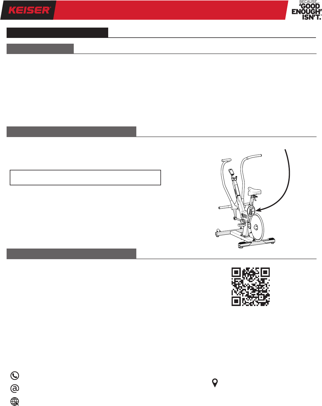
Register your Total Body Trainer to stay informed of safety
notications and for faster, more accurate warranty service.
Scan the QR Code to the right to access the interactive online
warranty registration form or visit:
https://www.keiser.com/forms/warrantyregistration
CUSTOMER SUPPORT
If you have any questions regarding the Total Body Trainer
installation and/or operation after reading this manual,
contact Keiser Customer Support:
1 559 256 8000
service@keiser.com
keiser.com/support
Please take a moment at this time to record the serial number
(“Serial No.”) in the space provided below.
Serial No.:
SCAN
Serial Number Location
KEISER CORPORATION
2470 S. Cherry Ave.
Fresno, CA 93706
GENERAL INFORMATION
INTRODUCTION
RECORD YOUR SERIAL NUMBER
REGISTER YOUR PURCHASE
M3i | M3 TOTAL BODY TRAINER
04
It is the sole responsibility of the purchaser of Keiser Corporation
equipment to instruct all individuals, whether they are the
end user or supervising personnel, on proper usage of the
equipment. Keiser Corporation recommends that all users of
its equipment be informed of the following information prior
to use.
1. Read these instructions. Keep these instructions.
2. Heed all warnings. Follow all instructions.
3. Use the Keiser M3i or M3 Total Body Trainer (herein
referred to as “TBT”) for its intended purpose as described
in this manual. Do no use attachments/accessories that
have not been recommended by the manufacturer.
4. User weight limit: 300 lbs (136 kg). User height range:
58–82 inches (1,473–2,083 mm).
5. Consult your physician before beginning any exercise
program.
6. Heart rate monitoring systems may be inaccurate. Over
exercising may result in serious injury or death. If you
feel faint, stop exercising immediately and consult your
physician.
7. The TBT is intended for use in training areas of
organizations where access and control is specically
regulated by a person responsible for determining the
suitability of use and maintenance.
8. Wear proper shoes. Dress shoes, sandals, slippers, or
bare feet are not suitable for use on the TBT. Quality
athletic shoes are recommended for proper support and
comfort. Do not wear clothing that might catch on any
TBT moving parts. Tie long hair back.
9. Distractions, such as watching television, reading, using a
computer device, or talking on the telephone while using
the TBT affect the ability of the user to safely exercise
on the TBT. Pay attention to and focus on your exercise
while using the TBT.
10. Routinely check and pay special attention to components
most susceptible to wear. Refer to the “Preventative
Maintenance Schedule” (page 21) for further instruction.
11. Immediately replace damaged, worn, or broken parts and
do not use the TBT until all repairs have been completed
and tested by a Keiser-certied technician.
12. Only use replacement parts recommended by Keiser
Corporation. Attempting to repair or replace any damaged,
worn, or broken parts on your own is not recommended.
A Keiser certied technician should be consulted.
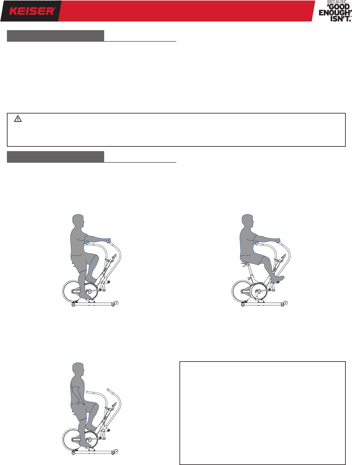
13. Proper posture and body position is necessary to achieve
a safe, comfortable, and effective workout. Correct foot
placement and arm reach must always be maintained
during every workout. Refer to the sections under “How
to Exercise on the TBT” (page 19) for further instruction
and safety information.
14. The TBT is NOT designed with a freewheel, but a xed
gear system. The Handles, Footpads, and Crank Arms
are attached by linked components. These cannot be
disengaged. When the Flywheel is in motion, the Pedals—
including the Handles—will also be in motion. For this
reason, never remove your feet from the Pedals or your
hands from the Handles while the Flywheel is in motion
as serious user injury may occur. Never take your hands
off the Handles while the Flywheel is in motion.
15. It is recommended that the TBT be pedaled in the forward
direction.
16. The Resistance Lever also functions as an Emergency
Brake, allowing you to safely slow or stop the motion of
the Flywheel. Move the Resistance Lever forward to slow
the motion of the Flywheel. Move the Resistance Lever
to the most forward position to engage the Emergency
Brake.
17. Do not make adjustments during exercise. Use the Handles
or the Resistance Lever to slowly bring all motion of the
TBT to a controlled stop prior to making adjustments.
18. Before dismounting the TBT, push the Resistance Lever
to the most forward position to engage the Emergency
Brake. Wait until the Footpads and Handles come to a
complete stop before dismounting.
19. Pedaling at high speeds or in the reverse direction, or
utilizing the TBT for independent upper or lower body
exercise, are considered advanced techniques and
should only be performed when the user has reached
an advanced level or under supervision by a person that
has reached an advanced level.
20. The TBT is not a toy. Children shall not play with the
TBT. Children under 14 years old should not use the TBT.
Keep children and pets clear from the TBT at all times,
especially while in use. Cleaning and user maintenance
shall not be performed by children.
21. The TBT can be used by children age 14 years and above.
Persons with mental disabilities, reduced physical, mental,
or sensory capabilities, or lack of experience or knowledge
should not use the TBT without constant supervision by
a spotter/supervisor.
22. The TBT should not be positioned in direct sunlight, in
areas of extreme temperature and humidity, or where
the TBT may be splashed with water or uids. The TBT
is intended for indoor use only.
23. The minimum amount of free area around the TBT is
24 inches (610 mm) on all sides. Refer to the “Training
Space” section (page 6) for further placement direction.
24. The TBT is suited for both home and commercial use.
To ensure your safety and to help prevent damage to
the TBT, read all instructions before operating. Seek
professional installation technicians if you are not able
to safely perform the work necessary to unpack, assemble,
and set the TBT in a desired exercise location.
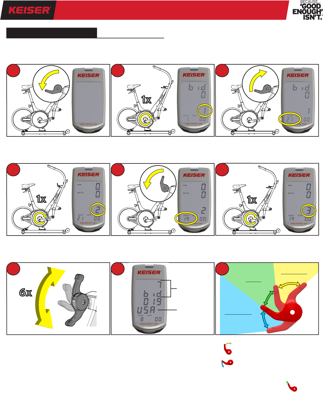
25. Failure to perform the “Proper Operation Check” (page 14)
prior to normal use of the TBT will void your warranty and
could result in serious injury.
26. The use of any exercise equipment, including, without
limitation, Keiser’s strength training equipment in
which resistance can be changed at anytime during the
IMPORTANT SAFETY INFORMATION
M3i | M3 TOTAL BODY TRAINER
05
WARNING: Incorrect or excessive exercise may cause injury. If you experience any kind of pain,
including but not limited to chest pains, nausea, dizziness, or shortness of breath, stop exercising
immediately and consult your physician before continuing.
repetition, and any xed gear bike, including, without
limitation, the Keiser TBT, without proper instruction and/
or supervision violates the terms of the agreement for
purchase of such products. The ability to add resistance
anytime during a repetition, including, without limitation,
the ability to do a heavy negative may be dangerous,
especially for anyone that does not recognize or respect
the potential danger. The inability to stop pedaling on a
xed gear bike before the ywheel stops may also be
dangerous to anyone riding, especially anyone that does
not recognize or respect the potential danger.
27. Users, agents, and/or anyone directing the use of the TBT
shall determine the suitability of the TBT for its intended
use, and said parties are specically put on notice that they
shall assume all risk and liability in connection herewith.
28. If you have any questions regarding TBT installation and/
or operation after reading this manual, contact Keiser
Customer Support:
CONVENTIONS USED
This manual contains the following marks:
WARNING: Indicates a hazardous situation that, if not
avoided, could result in death or serious injury.
CAUTION: Indicates a hazardous situation that, if not
avoided, could result in minor or moderate injury.
HEAVY OBJECT: Indicates help is required during lifting
to avoid muscle strain and/or back injury.
TWO-PERSON PROCEDURE: Indicates help is required
to safely and successfully complete installation.
IMPORTANT: Indicates information considered critical,
but not hazard-related.
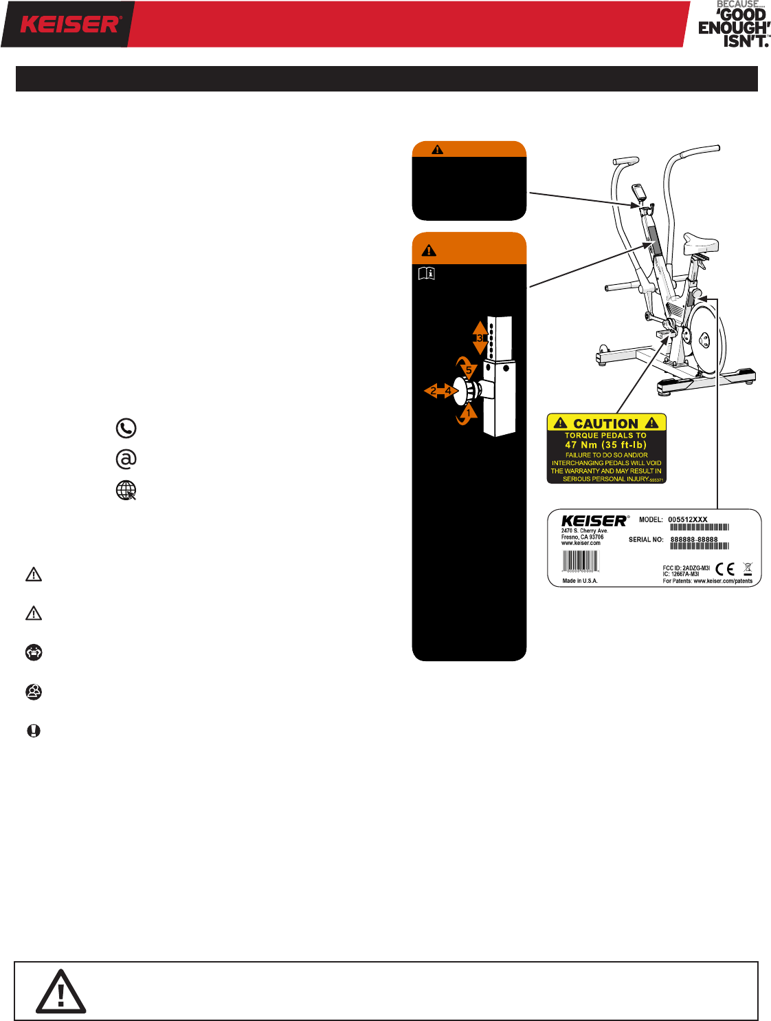
SAFETY AND SERIAL NUMBER LABELS
Maintain safety and serial number labels. Do not remove
labels for any reason. They contain important information.
If unreadable or missing, contact Keiser Corporation for a
replacement by telephone at 1 559 256 8000, online 24/7
at keiser.com/support, or by email at service@keiser.com.
1 559 256 8000
service@keiser.com
keiser.com/support
IMPORTANT SAFETY INFORMATION (CONTINUED)
Heart rate monitoring systems
may be inaccurate. Over
exercise may result in serious
injury or death. If you feel faint
stop exercising immediately.
555376
WARNING
555378
Consult a physician prior to use
and stop if you feel faint, dizzy,
or exhausted.
Refer to User Manual for
additional warnings and safety
information.
This machine must be used in a
supervised environment.
Keep children away.
Keep body, clothing, and
accessories clear from all
moving parts.
Inspect machine prior to use.
Immediately report worn, loose,
or damaged parts and refrain
from using the machine.
Always ride in control. Stop in a
controlled manner as flywheel
momentum will keep handles
and pedals turning.
Do not attempt to dismount bike
or remove hands from handles
or feet from pedals until pedals
have come to a complete stop.
Maximum user weight limit:
300 lbs (136 kg)
●
●
●
●
●
●
●
●
●
Seat Height
Adjustment
Instructions
Read the User Manual, follow
all instructions prior to use.
Ensure proper instruction is
attained prior to using this machine.
IMPROPER USE OF THIS MACHINE
CAN RESULT IN SERIOUS INJURY.
WARNING
M3i | M3 TOTAL BODY TRAINER
06
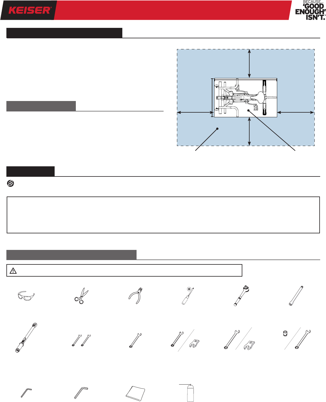
Figure 1. Training Space Illustration
The minimum amount of free area space around the TBT is
24 inches (610 mm) on all sides (refer to Figure 1).
When TBT equipment are positioned adjacent to each other,
the free area may be shared.
Height: 54 in (1,372 mm)
Depth: 49 in (1,245 mm)
Width: 29 in (737 mm)
Weight: 112 lbs (51 kg)
User weight limit: 300 lbs (136 kg)
User height range: 58–82 in (1,473–2,083 mm)
EQUIPMENT SPECIFICATIONS
ASSEMBLY
TRAINING SPACE
TOOLS AND MATERIALS REQUIRED
49 in
(1,245 mm)
24 in
(610 mm)
24 in
(610 mm)
24 in
(610 mm)
24 in
(610 mm)
29 in
(737 mm)
FREE AREATRAINING AREA
Safety GlassesScissorsCutting Pliers#2 Phillips
Screwdriver
3/8-inch Drive
Ratchet
6-inch Extension
Two 10 mm
Open-end Wrenches
1/2 inch (13 mm)
Wrench
15 mm Open-end
Wrench and Crowfoot
16 mm (5/8 inch)
Open-end Wrench
and Crowfoot
17 mm Socket or
Open-end Wrench
5 mm
Allen Wrench
6 mm
Allen Wrench
Clean ClothLPS 3
®
Rust Inhibitor or
WD-40
®
Long-Term
Corrosion Inhibitor
Torque Wrench
(35 ft-lb/47 Nm)
NOTE: Keiser Corporation is not responsible for damage or injury caused by incorrect installation, assembly or use.
• To avoid damaging parts, do not use power tools.
• Substitution or modication of any part or component,
other than what is provided by Keiser, will void your
warranty.
• Left-hand side Pedal is marked “CR-L” and right-hand side
Pedal is marked “CR-R.”
• Keep the packing materials until you successfully nish
all assembly steps.
TWO-PERSON PROCEDURE: Due to the size and weight of the equipment, assembly requires two persons to safely
and successfully complete installation.
CAUTION: Always follow tool manufacturer's safety and operating instructions.
M3i | M3 TOTAL BODY TRAINER
07
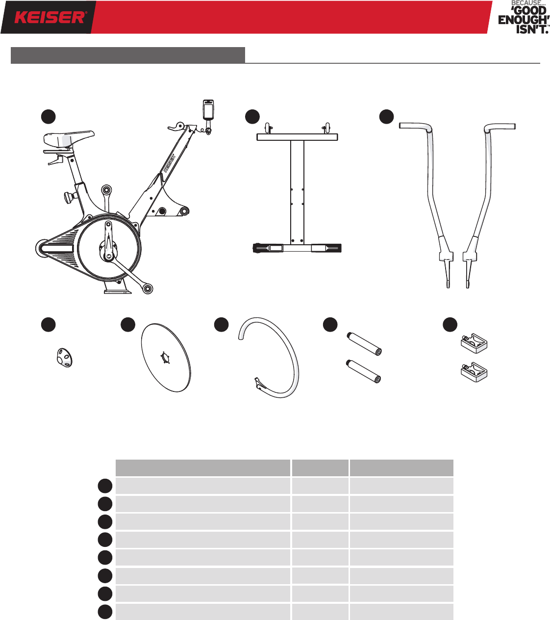
Figure 2. Parts List
PARTS LIST
Familiarize yourself with the parts below before you continue to the assembly procedure.
1
5
23
46
7
8
Description Keiser Part Number
Qty
6
Flywheel Guard and Cap553101, 555073
1
3
Left and Right Handles550832, 550833
1
5
Flywheel555503
1
8
Pedal Set5554381
4
Hubcap555005
1
2
Base550814
1
1
Main Frame with Computer Display550826, 550853/74
1
7
Foot Rest Set550834
1
M3i | M3 TOTAL BODY TRAINER
08
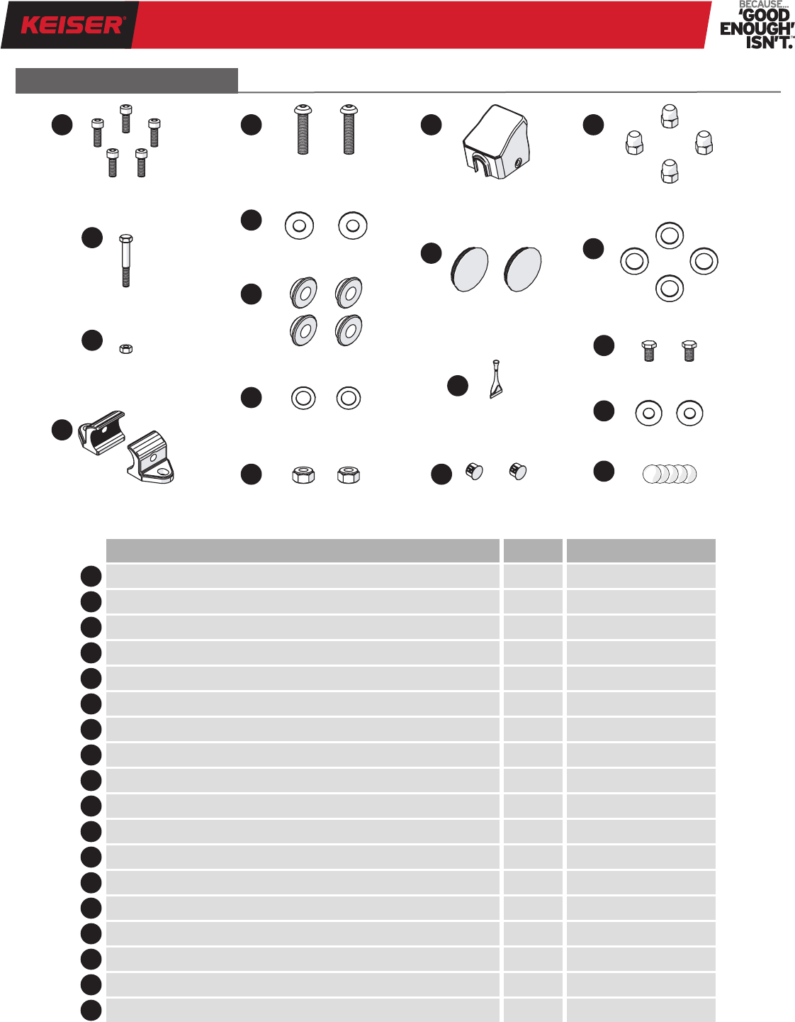
HARDWARE & FITTINGS
DescriptionQty Keiser Part Number
Socket Head Cap Screw (M6X1X18 SS)59547
A
Hex Elastic Lock Nut (M10X1.5 SS)29507
I
Socket Button Head Cap Screw (M10X1.5X45 SS)29526
E
Hole Plug2555439
M
Hex Head Cap Screw (M6X1X45 SS)19525
B
Shifter/Display Mount Cover1555082
J
C
Hex Nut (M6X1 SS)19508
K
Aluminum Caps (pre-assembled with O-rings)2565005
Flywheel Guard Clamp2555025
D
Loctite
®
242 Threadlocker1105550
L
Washer (FW .88X.39X.07 NP)2115450
F
Acorn Nut (7/16-20 SS)4555022
N
Bushing4305002
G
Washer (FW-ACFT 7/16 SS)49384
O
H
Washer (FW-ACFT-3/8 SS)29355
P
Hex Head Cap Screw (M8X1.25X16 ZP)29511
Q
Washer (FW-USS 5/16 ZP)29344
A
B
G
I
E
F
L
J
K
M
N
O
P
Q
R
C
H
D
Figure 3. Hardware and Fittings
Hub Cover Decal*5555379
R
* Hub Cover Decal will be shipped with, and are to be installed on, any TBT sold within the European Union only.
M3i | M3 TOTAL BODY TRAINER
09
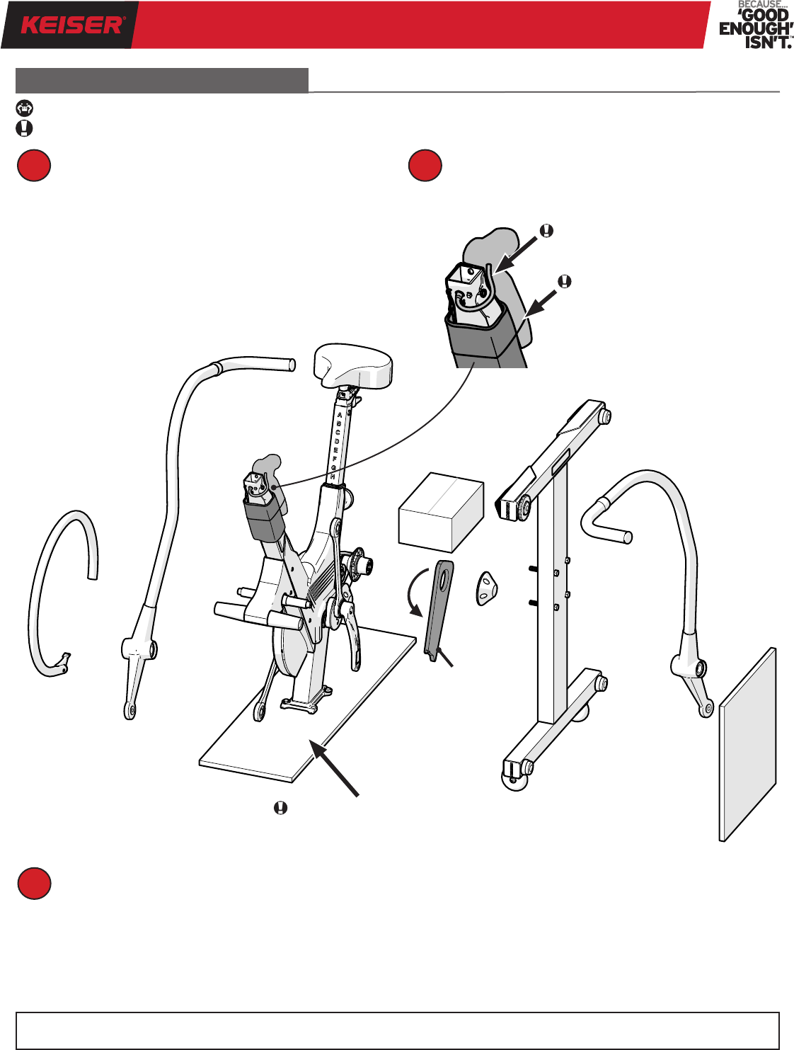
Place all parts in a cleared area check for missing parts. Refer to the Parts and Hardware & Fittings sections for
itemized lists (pages 7 and 8).
Position the TBT shipping box in a cleared area.
Pry up the top ap and tear down along a corner
seam to open the shipping box.
UNPACKING
HEAVY OBJECT: HELP REQUIRED WHEN LIFTING.
IMPORTANT: AVOID EQUIPMENT DAMAGE, DO NOT USE BOX CUTTERS.
Parts damaged in shipping or missing? Contact Keiser Customer Support by telephone at 1 559 256 8000, online 24/7
at keiser.com/support, or by email at service@keiser.com.
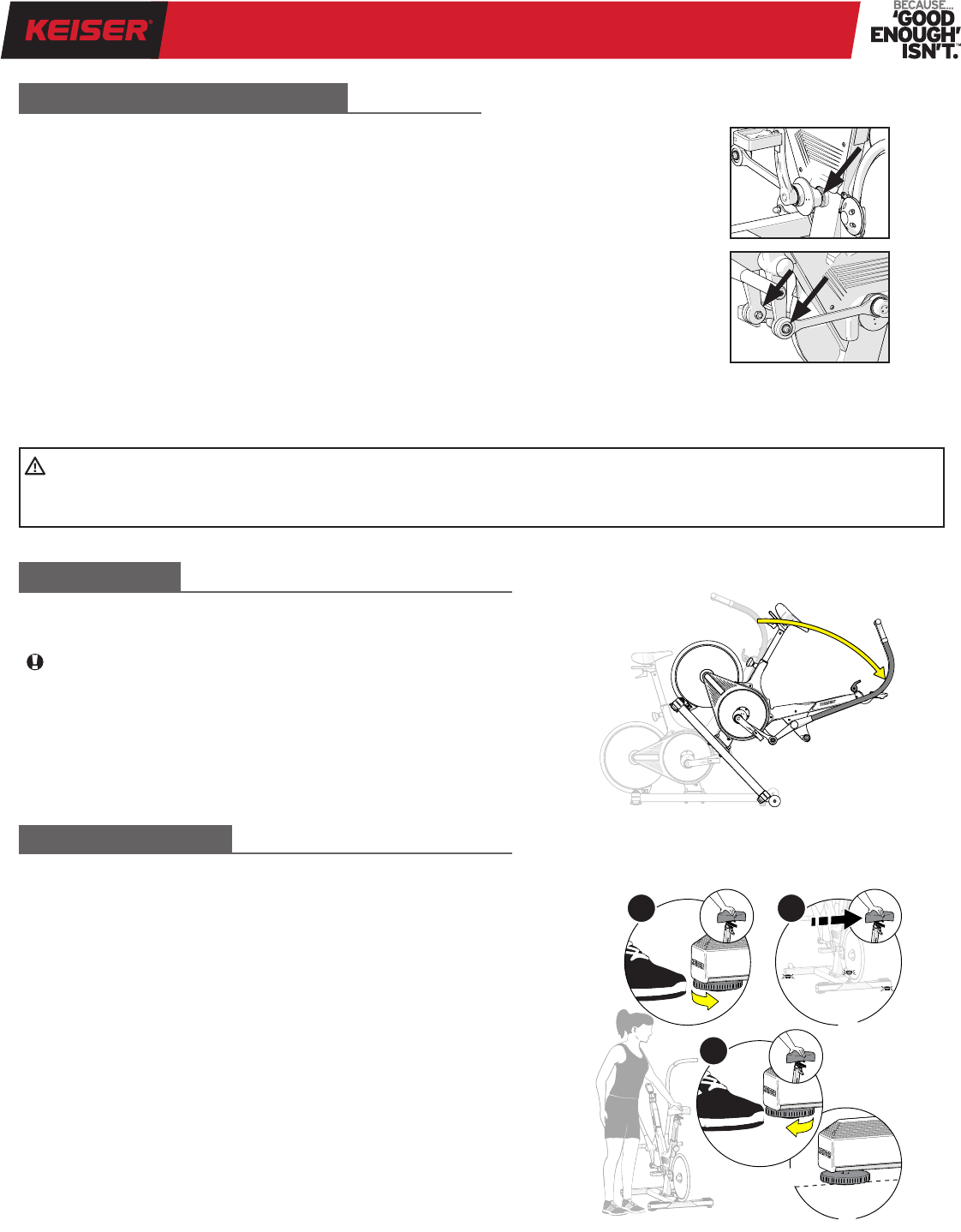
Swing
Axle Guard
Down, then
Pull Out
1
3
Carefully release the parts and boxes (shown below)
by cutting the stretch wrap, straps, and cable ties
using Scissors and Cutting Pliers.
2
IMPORTANT: DO NOT CUT
COMMUNICATION WIRE.
IMPORTANT: KEEP FRAME
ATTACHED TO SHIPPING BOARD.
IMPORTANT: KEEP COMPUTER
DISPLAY WRAPPED TO FRAME.
M3i | M3 TOTAL BODY TRAINER
10
(a) Position the front of the Main Frame facing the
Transport Wheels, then carefully lower the Main Frame
onto the Base over the Base Studs.
(b) Install one Washer and one Acorn Nut (Items O and N)
onto each Base Stud. Tighten Acorn Nuts using a 16 mm
(5/8 inch) Open-end Wrench. Torque to 35 ft-lbs (47 Nm)
using a 16 mm (5/8 inch) Crowfoot and Torque Wrench.
Prepare Base and Main Frame.
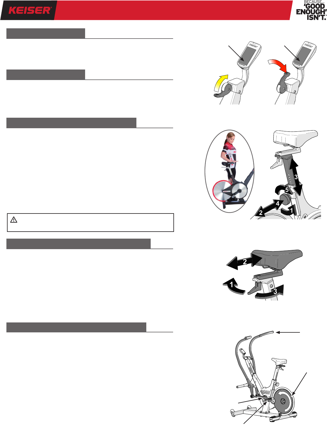
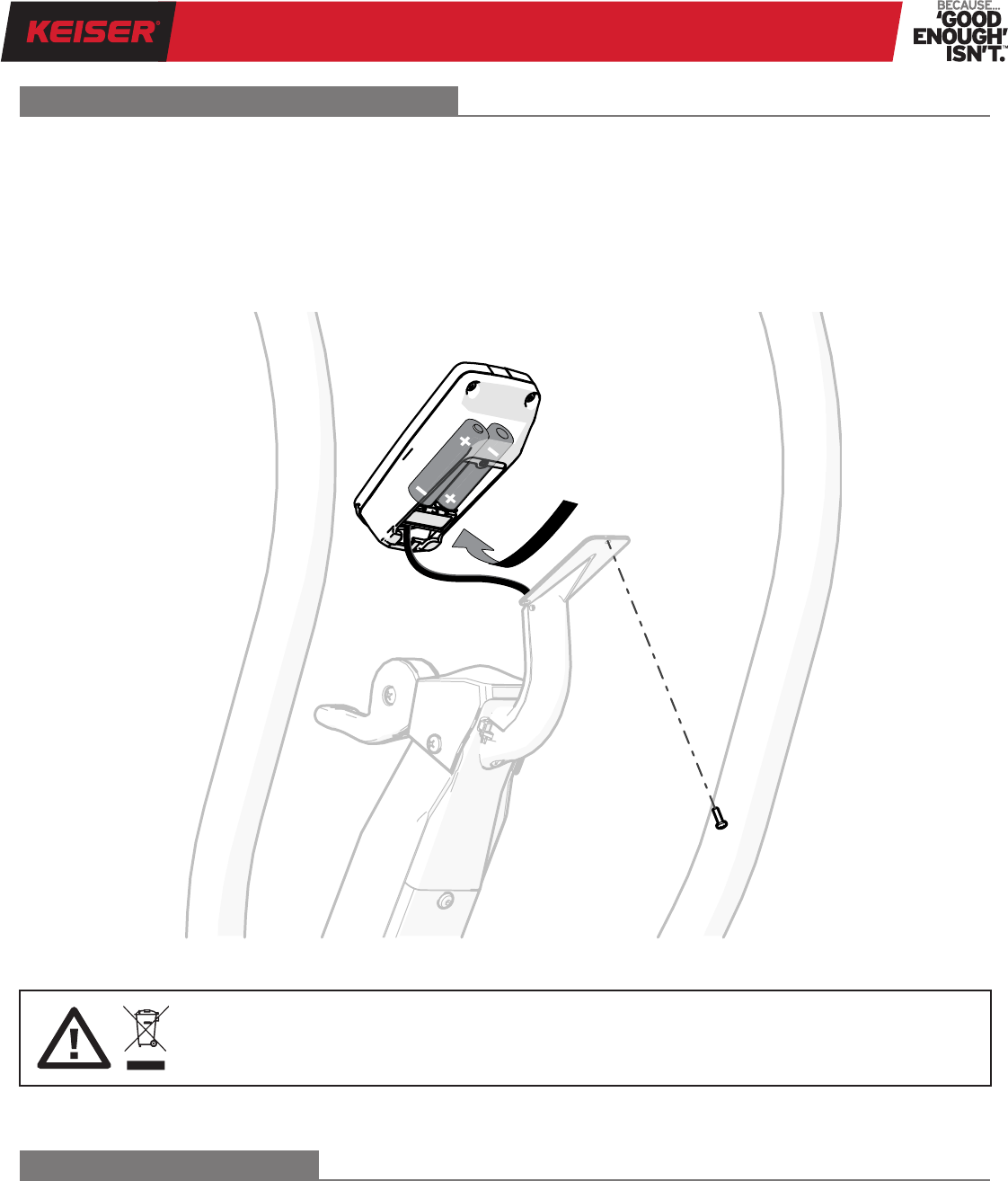
(a) Release the Computer Display from the packing
material and remove the Mount Screw using a #2 Phillips
Screwdriver.
(a) Slide the Computer Mount up and under the
Mount Tabs. Align the screw holes and install the
Mount Screw (removed in Step 3) using a #2 Phillips
Screwdriver.
(b) Coil the Communication Wire into the Computer
Mount Cavity. Avoid pulling/pinching the Communication
Wire.
(b) Remove the two screws along the side of the Sweat
Guard (#2 Phillips Screwdriver). Next, slide the Mount
Cap (Item J) into position. Install with the two original
screws.
Pull x3 Caps
off Base Studs
Mount Screw
Communication
Wire
Mount Screw
Screws
Mount Tabs
HOW TO ASSEMBLE THE TOTAL BODY TRAINER
1
3
2
4
Mount Cover
Computer Display
Computer Mount
REAR FRONT
Transport Wheels
O
N
Release Main Frame
from Shipping Board
(Tool: 1/2-inch Wrench)
M3i | M3 TOTAL BODY TRAINER
11
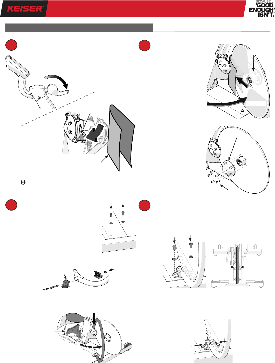
Prepare for Flywheel Guard Installation.
(a) Remove the two Mount Screws and
Washers from the Base using a 5 mm
Allen Wrench.
(b) Install the Clamps to the Flywheel Guard, nger tight
(Items B, C, and D).
(c) Place the open end of the Flywheel Guard onto the
Mount Stud, then swing the Flywheel Guard into position.
Prepare for Flywheel installation.
Align and secure the Flywheel Guard.
(a) Attach the Clamps to the Base using the two Screws/
Washers removed in Step 7a, do not tighten. Align the
Flywheel Guard to the Flywheel.
(b) Once the Flywheel Guard is aligned, tighten the two
Screws using a 5 mm Allen Wrench. Complete installation
by tightening the Bolt and Nut (Items B and C) using two
10 mm Wrenches.
5
7
(a) Pivot the Flywheel
into the folded paper and
onto the Hub. Push the
Flywheel up against the
Hub and align the screw
holes. Discard the folded
paper.
(b) Place the Hub Cap
onto the Hub and align
the screw holes. Install
ve SHC Screws (Item A).
Tighten the SHC Screws
in a star pattern using a
5 mm Allen Wrench.
NOTE: For equipment sold in
the European Union, apply a
Hub Cover Decal (Item R, not
shown) on the Hub Cap over
each of the SHC Screws.
6
8
HOW TO ASSEMBLE THE TOTAL BODY TRAINER
IMPORTANT: Failure to follow this step may
lead to cosmetic damage of the Flywheel.
Move Shifter to the
down position.
Wedge a folded piece of paper
between the Magnets.
A
Flywheel
Hub
Magnets
Flywheel Guard
B
B
C
C
D
Mount Stud
Hub Cap
M3i | M3 TOTAL BODY TRAINER
12
HOW TO ASSEMBLE THE TOTAL BODY TRAINER
9
11
(a) Clean the Pedal threads using a clean cloth, then
apply Loctite
®
242 Threadlocker (Item L) to the leading
threads of the Pedals.
(b) Use a 15 mm Open-end Wrench to install the Pedals to
the Crank Arms. LHS Pedal stamped “CR-L” thread left
Gebruikershandleiding.com neemt misbruik van zijn services uitermate serieus. U kunt hieronder aangeven waarom deze vraag ongepast is. Wij controleren de vraag en zonodig wordt deze verwijderd.
Product:
Spelregels forum
Om tot zinvolle vragen te komen hanteren wij de volgende spelregels:
lees eerst de handleiding door;
controleer of uw vraag al eerder door iemand anders is gesteld;
probeer uw vraag zo duidelijk mogelijk te stellen;
heeft u een probleem en al geprobeerd om dit op te lossen, vermeld dit erbij aub;
heeft u een oplossing gekregen van een bezoeker dan horen wij dat graag in dit forum;
wilt u een reactie geven op een vraag of antwoord, gebruik dan niet dit formulier maar klik op de knop 'reageer op deze vraag';
uw vraag wordt direct op de website gezet; vermijd daarom persoonlijke gegevens in te vullen;
Belangrijk! Als er een antwoord wordt gegeven op uw vraag, dan is het voor de gever van het antwoord nuttig om te weten als u er wel (of niet) mee geholpen bent! Wij vragen u dus ook te reageren op een antwoord.
Belangrijk! Antwoorden worden ook per e-mail naar abonnees gestuurd. Laat uw emailadres achter op deze site, zodat u op de hoogte blijft. U krijgt dan ook andere vragen en antwoorden te zien.
Abonneren
Abonneer u voor het ontvangen van emails voor uw Keiser M3i - Total Body Trainer bij:
nieuwe vragen en antwoorden
nieuwe handleidingen
U ontvangt een email met instructies om u voor één of beide opties in te schrijven.
Ontvang uw handleiding per email
Vul uw emailadres in en ontvang de handleiding van Keiser M3i - Total Body Trainer in de taal/talen: Engels als bijlage per email.
De handleiding is 7,39 mb groot.
U ontvangt de handleiding per email binnen enkele minuten. Als u geen email heeft ontvangen, dan heeft u waarschijnlijk een verkeerd emailadres ingevuld of is uw mailbox te vol. Daarnaast kan het zijn dat uw internetprovider een maximum heeft aan de grootte per email. Omdat hier een handleiding wordt meegestuurd, kan het voorkomen dat de email groter is dan toegestaan bij uw provider.
Stel vragen via chat aan uw handleiding
Stel uw vraag over deze PDF
Uw handleiding is per email verstuurd. Controleer uw email
Als u niet binnen een kwartier uw email met handleiding ontvangen heeft, kan het zijn dat u een verkeerd emailadres heeft ingevuld of dat uw emailprovider een maximum grootte per email heeft ingesteld die kleiner is dan de grootte van de handleiding.
Er is een email naar u verstuurd om uw inschrijving definitief te maken.
Controleer uw email en volg de aanwijzingen op om uw inschrijving definitief te maken
U heeft geen emailadres opgegeven
Als u de handleiding per email wilt ontvangen, vul dan een geldig emailadres in.
Uw vraag is op deze pagina toegevoegd
Wilt u een email ontvangen bij een antwoord en/of nieuwe vragen? Vul dan hier uw emailadres in.