590147
43
Verklein
Vergroot
Pagina terug
1/172
Pagina verder
Quick Reference Guide
SAFETY INFORMATION j
GENERAL INFORMATION j
HOW TO RIDE THE MOTORCYCLE j
MAINTENANCE AND ADJUS TMEN T j
APPENDIX j
MAINTENANCE RECORD j
This Quick Reference Guide will
assist you in finding the information
you’re looking for.
A Table of Contents is included after
the Foreword.
Whenever you see the symbols
shown below, heed their instructions!
Always follow safe operating and main-
tenance practices.
DANGER
DANGER indicates a hazardous
situation which, if not avoided,
will resu lt in death or serious in-
jury.
WARNING
WARNING indicates a hazardous
situation which, if not avoided,
could result in death or serious
injury.
NOTICE
NOTICE is used to address prac-
tices not related to personal in-
jury.
NOTE
NOTE ind icates informat ion that may
help or guide you in the operation or
service of the vehicle.
NOTICE
THIS PRODUCT HAS BEEN
MANUFACTURED FOR USE IN A
REASONABLE AND PRUDENT
MANNER BY A QUALIFIED OP-
ERATOR AND AS A VEHICLE
ONLY.
Foreword
Congratulations on your purchase of a new Kawasaki motorcycle. Your new mo-
torcycle is the product of Kawasaki’s advanced engineering, exhaustive testing,
and continu o us striving for superior reliability, safety and performance.
Please read this Owners Manual carefully before riding so that you will be
thoroughly familiar with the proper operation of your motorcycle’s controls, its fea-
tures, capabilities, and limitatio ns. This manua l offers ma n y safe riding tips, but its
purpose is not to pro vid e instruc tio n in all the techniqu es and skills required to ride
a motorcycle safely. Kawasaki strongly recommends that all operators of this vehi-
cle enroll in a motorcycle rider trainin g program to attain aw areness of the mental
and physical requirements necessary for safe m otorcycle operation.
To ensure a long, trouble-free life for your motorcycle, give it the proper care and
maintenance described in this manual. For those w ho would like more detailed in-
formation on their Kawasaki Motorcycle, a Service Manual is available fo r purchase
from any authorized Kawasaki motorcycle dealer. The Service Manual contains de-
tailed disassembly and maintenance information. Those who plan to do their own
work should, of course, be competent mechanics and possess the special tools
described in the Service Manual.
Keep this Owner’s Manual aboard your motorcycle at all times so that you can
refer to it whenever you need information.
This manual should be considered a permanent part of the motorcycle and should
remain with the motorcycle when it is sold.
All rights reserved. No part of this publication may be reproduced without our
prior written permission.
This publication includes the latest information available at the time of printing.
However, the r e may be minor differences between the actual product and illu stra -
tions and text in this manual.
All products are subject to change without prior notice or obligation.
KAWASAKI HEAVY INDUSTRIES, LTD.
Motorcycle & Engine Company
© 2014 Kawasaki Heavy Industries, L td. Aug. 15, 2 014. (2)
(Australian model only)
TAMPERING WITH NOISE CONTROL SYSTEM
PROHIBITED
Owners are warned that the law may prohibit:
(a) The removal or rendering inoperativ e by any person other than for purposes
of maintenance, repair or replacement, of any device or element of design
incorporated into any new vehicle for the purpose of noise control prior to
its sale or delivery to the ultimate purchase r or while it is in u se; and
(b) The use of the vehicle after such device or element of design has been
removed or rendered inoperative by any person.
TABLE OF CONTENTS
SAFETY INFORMATION .................... 10
Read Owner’s Manual ..................... 10
Training ............................................ 10
Daily Checks and Periodic
Maintenance ................................. 10
Loading and Accessories
Information.................................... 11
Passenger .................................... 12
Baggage and Luggage ................. 13
Accessories .................................. 13
Other Load.................................... 14
If You are Involved in an Accident.... 14
Safe Operation................................. 15
Carbon Monoxide Hazard............. 15
Fueling.......................................... 16
Never Ride with Drugs or Alcohol. 16
Protective Gear and Clothing ....... 16
Safe R iding Techniques................ 17
Additional Considerations for High
Speed Operation ....................... 19
GENERAL INFORMATION................. 21
Specifications................................... 21
Serial Number Locations.................. 26
Location of Labels............................ 27
Location of Parts .............................. 38
Meter Instruments ............................ 41
Indicators ...................................... 42
Speedometer/Tachometer ............ 49
Display Setting.............................. 50
Clock............................................. 54
Features ....................................... 55
Keys ................................................. 57
Ignition Switch/Steering Lock ........... 57
Right Handlebar Switches................ 59
Left Handlebar Switches .................. 60
Brake Lever Adjuster........................ 61
Clutch Lever Adjuster....................... 62
Fuel .................................................. 63
Fuel Requirements ....................... 63
Filling the Tank.............................. 65
Side Stand ....................................... 68
Seat.................................................. 68
Tool Kit ............................................. 69
Rear View Mirrors ............................ 70
Windshield........................................ 70
Tie Hooks ......................................... 71
Helmet Hooks................................... 72
Event Data Recorder........................ 72
Electric Accessory Connectors ........ 73
HOW TO RIDE THE MOTORCYCLE .76
Break-In ........................................... 76
Starting the Engine .......................... 77
Jump Starting................................... 80
Moving Off........................................ 82
Shifting Gears .................................. 83
Braking............................................. 84
Anti-lock Brake System (ABS) ......... 85
Stopping the Engine......................... 88
Stopping the Motorcycle in an
Emergency ................................... 88
Parking............................................. 89
MAINTENANCE AND ADJUSTMENT 92
Daily Checks .................................... 94
Periodic Maintenance....................... 97
Engine Oil ........................................ 102
Coolant............................................. 106
Air Cleaner ....................................... 114
Throttle Control System ................... 115
Idle Speed........................................ 117
Clutch............................................... 118
Drive Chain ...................................... 119
Brakes.............................................. 124
Brake Light Switches........................ 127
Suspension System ......................... 128
Front Fork ..................................... 128
Rear Shock Absorber ................... 130
Setting Tables ............................... 132
Wheels ............................................. 135
Battery.............................................. 138
Headlight.......................................... 142
Fuses ............................................... 143
General Lubrication.......................... 147
Cleaning Your Motorcycle ................ 148
General Precautions..................... 148
Washing Your Motorcycle ............. 150
APPENDIX .......................................... 154
Storage ............................................ 154
Troubleshooting Guide..................... 157
Owner Satisfaction........................... 162
Environmental Protection................. 164
MAINTENANCE RECORD ................. 165
10 SAFETY INFORMATION
j
SAFETY INFORM ATION
Read Owners Manual
Read this Owner’s Manual care-
fully before riding so that you will be
thoroughly familiar w ith the proper op-
eration of your motorcycle’s controls,
its features, capabilities, and limita-
tions. This manual offers many safe
riding tips, but its purpose is not to pro-
vide instruction in all of the techniques
and skills required to ride a motorc ycle
safely.
Training
Kawasaki strongly recommends that
all operators of this vehicle complete a
suitable motorcycle rider training pro-
gram to learn the p roper skills an d tech-
niques necessary for safe m otorcycle
operation.
DailyChecksandPeriodic
Maintenance
It is important to keep your motorcy-
cle properly maintained and in safe rid-
ing condition. Inspect your m otorcy-
cle before every ride and carry out all
periodic maintenance. See the Daily
Checks section and the Periodic M ain-
tenance section in the MAINTENANCE
AND ADJUSTMENT chapter for more
informa tion.
WARNING
Failure to perform these checks
or to correct a problem before
operation may result in serious
damage or an accident. Always
perform daily checks before op-
eration.
SAFETY INFORM ATION 11
j
To ensure your motorcycle is ser-
viced using the latest servicing infor-
mation, it is recommended that an
authorized Kawasaki Dealer performs
the periodic maintenance a s directed
in the Owner’s Manual.
If you notice any irregular o perat-
ing condition, have your motorcycle
thoroughly checked at an authorized
Kawasaki dealer as soon as possible.
Loading and Accessories
Information
WARNING
Incorrect loading, improper in-
stallation or use of accessories,
or modification of your motorcy-
cle may result in an unsafe riding
condition. Before you ride the
motorcycle,makesureitisnot
overloaded and that you have
followed these in structions.
Maximum Load
Weight of rider, passenger, baggage,
and accessories must not exceed 210 kg
(463 lb).
With the exception of genuine
Kawasaki Parts and Accessories,
Kawasaki has no control over the
design or application of a ccessories.
In some cases, improper installation
12 SAFETY INFORMATION
j
or use of a ccessories, or motorcycle
modification, will void the motorcycle
warranty; can negatively affect perfor-
mance, sta bility and sa fety; and c an
even be illegal.
In selecting and using accessories ,
and in loading the motorcycle, you are
personally responsible for your own
safety and the safety of other persons
involved.
NOTE
Kawasaki Parts and Accessories
have been specially designed for
use on Kawasaki motorcycles. We
strongly recommend that all parts
and accessories you add to your
motorcycle be genuine Kawasaki
components.
Because a motorcycle is sensitive to
changes in weight and aerodynamic
forces, you must take extreme care in
carrying cargo, passengers and/or in
fitting additional accessories. The fol-
lowing general guidelines have been
prepared to assist you in making y our
determinations.
Passenger
1. Never carry more than one passen-
ger.
2. The passenger should only sit on the
pillion.
3. Any passenger should be thor-
oughly familiar with motorcycle op-
eration. The passenger can affect
control of the motorcycle by im-
proper positioning during cornering
and sudden movements. It is im-
portant that the passenger sits still
while the motorcycle is in m o tion
and not interfere with the operation
of the motorcycle. Do not carry ani-
mals on your motorcycle.
SAFETY INFORMATION 13
j
4. Do not carry passengers unless
passenger footpegs are installed.
Instruct any passenger before riding
to keep his or her feet on the pas-
senger footpegs and hold on to the
operator or grab rail. Do not carry
a passenger unless he or she is tall
enough to reach the footpegs with
their feet.
Baggage and Luggage
1. All baggage should be carried as
low as possible to reduce the effect
on the m otorcycle’s center of grav-
ity. Baggage weight should also be
distributed equally on both sides of
the m otorcycle. Avoid carrying bag-
gage that extends beyond the rear
of the motorcycle.
2. Baggage should be securely at-
tached. Make sure that the baggage
will not move aroun d while you are
riding. Recheck baggage security
as often as possible (not while the
motorcycle is in m otion) and adjust
as necessary.
3. Do not carry heavy or bulky items
on a luggage rack. It is designed
for ligh t items, and overloading can
affect handling due to changes in
weight distribution and aerodynamic
forces.
Accessories
1. Do not install accessories or carry
baggage that impairs the perfor-
mance of the motorcycle. Make
sure that you have not adversely
affected any lighting components,
road clearance, banking capability
(i.e., lean angle), control operation,
wheel travel, front fork movement,
14 SAFETY INFORMATION
j
or any other aspects of the motor-
cycle’s operation.
2. Weight attached to the handlebars
or front fork will increase the mas s
of the steering assembly and can
result in an unsafe riding condition.
3. Fairings, windshields, backrests,
and other large items have the ca-
pability of adversely affecting stabil-
ity and handling of the motorcycle,
not only due to their weight, but
also due to the aerodynamic force
acting on these surfaces while the
motorcycle is in operation. Poorly
designed or installed items can re-
sult in an unsafe riding condition.
Other Load
1. This motorcycle is not intended to
be equipped with a sidecar or to be
used to tow any trailers or other ve-
hicles. Kawasaki does not manu-
facture sidecars or trailers for mo-
torcycles and cannot predict the ef-
fects of such accessories on han-
dling or s ta bility, but can only warn
thattheeffectscanbeadverseand
that Kawasaki cannot assume re-
sponsibility for the results of such
unintended use of the motorcycle.
2. Furthermore, any adverse effects on
motorcycle components caused by
the use of such accessories will not
be remedied under warranty.
If You are Involved in an
Accident
Make sure of your own safety first.
Determine the severity of any injuries
and call for emergency a ssistance if
needed. Always follow applicable laws
SAFETY INFORMATION 15
j
and regulations if any other person, ve-
hicle or property is involve d.
Do not attempt to continue riding
without first evaluating you r motorcy-
cle’s condition. Inspect for fluid leaks,
check critical nuts and bolts, and check
the handlebars, control levers, b rakes,
and wheels for damage and proper
function. Ride slowly and cautiously
- your motorcycle may have suffered
damage that is not immediately appar-
ent. Have your motorcycle thoroughly
checked at a Kawasaki dealer as soon
as possible.
Safe Operation
The following should be carefully ob-
served for safe and effective vehicle
operation.
Carbon Monoxide Hazard
DANGER
Exhaust gas contains carbon
monoxide, a colorless, odor-
less poisonous gas. Inhaling
carbon monoxide can cause
serious brain injury or death.
DO NOT run the engine in en-
closed areas. Operate only in a
well-ventilated area.
16 SAFETY INFORMATION
j
Fueling
WARNING
Gasoline is extremely flammable
and can be explosive under
certain conditions. To avoid a
possible fire or explosion, turn
the ignition switch off. D o not
smoke. Make sure the area is
well ventilated and free from any
source of flame or sparks; this
includes any appliance with a
pilot light.
Never Ride with Drugs or Alcohol
Alcohol and drugs impair your judg-
ment and reaction time. Never con-
sume alcohol or drugs before or while
riding motorcycles.
Protective Gear and Clothing
Helmet
Kawasaki strongly recommends both
the operator and passenger wear a hel-
met even if this is not a legal require-
ment.
- Make sure that your helmet fits cor-
rectly and is properly fastened.
- Choose a m ot orcycle helm et that
meets the safety standards appli-
cable to your country. Ask y our
motorcycle dealer to advise you if
necessary.
SAFETY INFORMATION 17
j
Eye Protection
Always use eye protection. If your
helmet does not have a visor installed,
wear goggles.
Gloves
Wear gloves which have suitable
protection for your hands, especially
against abrasion.
Clothing
Wear protective clothing.
- Wear b rig h t, highly visible clothing
that allows freedom of movement
to suit your riding style.
- Always wear a long- sleeved jac ket
and long tro users w h ich are abra-
sion resistant and keep you warm.
- Avoid wearing clothes which have
loose cuffs or other fastenings
which could interfere with the con-
trols of your motorcycle.
Boots
Wear proper protective boots that fit
properly and do not interfere with gear
shifting or braking.
Safe Riding Techniques
Keep Hands on Handlebars
When riding always keep both hands
on the handlebars and both feet on the
footpegs. Removing your hands from
the handlebars or feet from the foot-
pegs while riding can be hazardous. If
you remove even one hand or foot, you
reduce your ab ility to c on trol the motor-
cycle.
Look Over Your Shoulder
Before changing lanes, look over
your shoulder to make sure the way
is clear. Do not rely solely on the rear
18 SAFETY INFORMATION
j
view mirror; you may misjudge a vehi-
cle’s distance and speed, or you may
not see it at all.
Accelerate and Brake Smoothly
In general your actions should be
smooth as sudden acceleration, brak-
ing or turning may cause loss of control,
especially when riding in wet conditions
or on loose road surfaces, when the
ability to maneuver will b e reduced.
Select Correct Gear Speeds
When going up steep slopes, shift to
a lower gear so that there is power to
spare rather than overloading the en-
gine.
Use Both Front and Rear Brakes
When applying the brakes, use both
the front and rear brakes. Applying
only one brake for sudden braking may
cause the motorcycle to skid and lose
control.
Use Engine Brake
When going down long slopes, help
control vehicle speed by closing the
throttle so that the engine can act as an
auxiliary brake. Use the front and rear
brakes for primary braking.
Riding in Wet Conditions
Rely more on the throttle to c ontrol
vehicle s peed and less on the front and
rear brakes. The throttle should also be
used judiciously to avoid skidding the
rear wheel from too rapid acceleration
or deceleration.
Braking perform ance is also reduced
in wet conditions. Carefully ride at a
slow speed and apply the brakes sev-
eral times to help dry and restores them
to normal operating performance.
Lubricate the drive chain after wet
-weather riding to prevent rust and cor-
rosion.
SAFETY INFORMATION 19
j
Ride Prudently
Riding at the proper speed and avoid-
ing unnecessarily fast acceleration are
important not only for safety and low
fuel consumption but also for lon g ve-
hicle life and quieter operation.
Riding on Rough Roads
Exercise caution, slow down, and
grip the fuel tank with the knees for
better stability.
Acceleration
When quick acceleration is neces-
sary to pass another vehicle, shift to
a lower gear to obtain the necessary
power.
Downshifting
To avoid engine damage and rear
wheel lock-up do not downshift at high
rpm.
Avoid Unnecessary Weaving
Unnecessary weaving jeopardizes
the safety of both the rider and other
motorists.
Additional Considerations for
High Speed Operation
WARNING
Handling characteristics of a
motorcycle at high speeds may
vary from those you are familiar
with at legal highway speeds.
Do not attempt high speed oper-
ation unless you have received
sufficient training and have the
required sk il ls.
Do not operate at high speeds on
public roads.
20 SAFETY INFORMATION
j
Brakes
The importance of the brakes, es -
pecially during high speed operation,
cannot be overemphasized. C heck to
see that they are correctly adjusted and
functioning properly.
Steering
Looseness in the steering can cause
loss of control. Ch eck to see that the
handlebars turns freely but has no play.
Tires
High speed operation is hard on tires,
and good tires are crucial for safe rid-
ing. Examine their overall condition, in-
flate them to the proper pressure, and
check the wheel balance.
Fuel
Have sufficient fuel for the high fuel
consumption during high speed opera-
tion.
Engine Oil
To avoid engine seizure and resulting
loss of control, make sure that the oil
level is at the upper level line.
Coolant
To avoid overheating, check tha t th e
coolant level is at the upper level line.
Electrical Equipment
Make sure that the headlight,
tail/brake light, turn signals, horn, etc.,
all work properly.
Miscellaneous
Make sure that all nuts and bolts are
tight and that all safety related parts are
in good condition.
GENERAL INFORMATION 21
j
GENERAL INFORMATION
Specifications
PERFORMAN
CE
Maximum Horsepower
51 kW (69 PS) @8 500 r/min (rpm)
(AU LAMS) 39 kW (53 PS) @7 800 r/min (rpm)
Maximum Torque
64 N·m (6.5 kgf·m, 47 ft·lb) @7 000 r/min (rpm)
(AU LAMS) 57 N·m (5.8 kgf·m, 42 ft·lb) @3 800 r/min (rpm)
Minimum Turning Radius
2.7 m (1 0
6in.)
DIMENSI
ONS
Overal
l Length
2 165 mm
(85.24 in.)
Overal
lWidth
840 mm (
33.1 in.)
Overal
l Height/High Pos ition
1400mm
(55.12 in.)/1 450 mm (57.09 in.)
Wheelbase
1 415 mm
(55.71 in.)
Road C
learance
170 mm
(6.69 in.)
22 GENERAL INFORMATION
j
Curb Mass
(KLE650E) 214 kg (472 lb)
(KLE650F) 216 kg (476 lb)
ENGINE
Type DOHC, 2-cylinder, 4-stroke, liquid-cooled
Displacement 649cm³(39.6cuin.)
Bore × Stroke 83.0 × 60.0 mm (3.3 × 2.4 in.)
Compression Ratio 10.8:1
Starting System Electric starter
Cylinder Numbering M ethod Left to right, 1-2
Firing Order 1-2
Fuel System FI (Fuel I njection)
Ignition System Battery and coil (transistorized ignition)
Igniti
on Timing
(Electronically advanced)
10° BTDC @1 300 r/min (rpm) 56° BTDC @5 200
r/min (rpm)
Spark Plug:
Type
NGK CR9EIA-9
Gap 0.8 0.9 mm (0.031 0.035 in.)
Lubrication System Forced lubrication (semi-dry sump)
GENERAL INFORMATION 23
j
Engine Oil: Type API SG, SH, SJ, SL, or SM with JASO MA, MA1 or MA2
Viscosity SAE 10W-40
Capacity 2.3 L (2.4 US qt)
Coolant Capacity 1.2 L (1.3 US qt)
TRANSMISSION
Transmissi on Type 6-speed, constant mesh , return shift
Clutch Type Wet, multi disc
Driving System Chain drive
Primary Reduction Ratio 2.095 (88/42)
Final R eduction Ra tio 3.067 (46/15)
Overall Drive Ratio 5.473 (Top gear)
Gear Ratio: 1st 2.438 (39/16)
2nd 1.714 (36/21)
3rd 1.333 (32/24)
4th 1.111 (30/27)
5th 0.966 (28/29)
6th 0.852 (23/27)
24 GENERAL INFORMATION
j
FRAME
Caster 25°
Trail 108 mm (4.25 in.)
Tire Size: F ront 120/70ZR17 M/C (58W)
Rear 160/60ZR17 M/C (69W)
Rim S i ze: Front J17M/C × MT3.50
Rear J17M/C × MT4.50
Fuel Tank Capacity 21 L (5 .5 US gal)
Brake Fluid: Front DOT4
Rear DOT4
ELECTRICAL EQUIPMENT
Battery 12 V 10 Ah (10 HR)
Headlight: High Beam 12 V 55 W
Low Beam 12 V 55 W
Brake/Tail Light LED
AU LAMS: Australia Leaner Approved Motorcycle Scheme model
GENERAL INFORMATION 25
j
Even if one of LED (Light Emitting Diode) brake/tail light does not go on, consult
with an authorized Kawasaki dealer.
Specifications are subject to change without notice, and may not apply to every
country.
26 GENERAL INFORMATION
j
Serial Number Locations
The eng in e and frame serial numbers are used to reg ister the m ot orcycle. The y
are the only means of identifying your particular machine from others of the same
model type. These serial numbers ma y b e needed by your d ealer when ordering
parts. In the event of theft, the investigating authorities will require both numbers
as well as the model type and any peculiar features of your machine that can help
them identify it.
Engine No.
A. Engine Number
Frame No.
A. Frame Number
GENERAL INFORMATION 27
j
Location of Labels
All warning labels which are on your
vehicle are repeated here. Read labels
on your vehicle and understand them
thoroughly. They contain information
which is important for your safety and
the safety of anyone else who m ay op-
erate your vehicle. Th eref ore, it is very
important that all warning labels be on
your vehicle in the locations show n. If
any label is missing, damaged, or worn,
get a replacement from your Kawasaki
dealer and install it in the correct posi-
tion.
NOTE
The sample warning labels in this
section have part numbers to help
you and your dealer obtain the cor-
rect replacement.
Refer to the actual vehicle label for
model spe cific data grayed o ut in the
illustration.
1. Brake Fluid (Front)
28 GENERAL INFORMATION
j
2. Brake Fluid (Rear)
3. Battery Poison/Danger
4. Rear Shock Absorber Warning
GENERAL INFORMATION 29
j
5. Radiator Cap Dan ger
*
1
6. Coolant Notice
*
1
7. Safety Riding Notice
*
2
8. Helmet Wearing
*
3
9. Vehicle Emission Control Information
*
4
10. Vacuum Hose Rou ting Diagram
*
1
11. Fuel Notice
*
4
12. Fuel Level
*
1
: only on Ind onesia model
*
2
: only on T hailand model
*
3
: only on Philippines model
*
4
: only on Thailand and S o utheast Asia
B1 models
30 GENERAL INFORMATION
j
13. Tire and Load Data
14. Important Drive Chain Information
*
5
15. Noise Test Information
*
6
16. Stationary Noise Test Information
*
2
17. Vehicle Emission Control Informatio n
*
2
: only on T hailand model
*
5
: only on M alays ia and Southeast Asia
B2 models
*
6
: only on A ust ra lia model
GENERAL INFORMATION 31
j
1)
2)
3)
32 GENERAL INFORMATION
j
4) 5)
6) only on Indonesia model
GENERAL INFORMATION 33
j
7) only on Indonesia model
8) only on Thailand model
9) only on Philippines model
10) only on Thailand model
34 GENERAL INFORMATION
j
10) only on Southeast Asia B1 model
11) only on Indonesia model
12) only on Thailand model
12) only on Southeast Asia B1 model
GENERAL INFORMATION 35
j
13) Except Indonesia and Thailand
models
13) only on Indonesia model
13) only on Thailand model
14) Except Indonesia and Thailand
models
36 GENERAL INFORMATION
j
14) only on Indonesia model
14) only on Thailand model
15) only on Malaysia and Southeast
Asia B2 models
16) only on Australia model
GENERAL INFORMATION 37
j
17) only on Thailand model
38 GENERAL INFORMATION
j
Location of Parts
1. Rear View Mirrors
2. Starter Lo cko ut Switch
3. Windshield Adjusting Knobs
4. Meter Instrument
5. Brake Fluid Reservoir (Front)
6. Clutch Lever
7. Left Handlebar Switches
8. Spring Preload Adjuster
9. Ignition Switch/Steering Lock
10. Rebound Damping Force Adjuster
11. Right Handlebar Switches
12. Throttle Grip
13. Front Brake Lever
GENERAL INFORMATION 39
j
1. Headlight
2. Spark Plugs
3. Air Cleaner
4. Fuel Tank
5. Seat
6. Helmet Hook
7. Tie Hook s
8. Turn Signal Lights
9. License Plate Lig ht
10. Seat Lock
11. Chain Adjuster
12. Drive Chain
13. Side Stand
14. Shift Pedal
15. Side Stand Switch
16. Oil Filter
17. Front Fork
40 GENERAL INFORMATION
j
1. Tail/Brake Light
2. Brake Fluid Reservoir (Rear)
3. Fuse Boxes
4. Battery
5. Fuel Tank Cap
6. Coolant Reserve Tank
7. Brake Discs
8. Brake Calipers
9. Idle Adjusting Screw
10. Oil Level Inspection Window
11. Rear Brake Pedal
12. Rear Brake Light Switch
13. Muffler
14. Rear Shock Ab sorber
15. Spring Preload Adjuster
GENERAL INFORMATION 41
j
Meter Instruments
1. Tachometer
2. Left Meter Button
3. Right Meter Butto n
4. Multifunction Meter
5. Fuel Gauge
6. Economical Riding Indicator
7. Speedometer
8. Multifunction Di s play
-Odometer
- Trip M eter A/B
- Current Mileage/Ave ra ge Mileage/Cru ising
Range
9. Clock
When the ignition switch is turne d on, all LC D
functions are shown for a few seconds, then the
multifunction meter turns to operational mode.
42 GENERAL INFORMATION
j
Indicators
1. Left Turn Signal Indicato r (Green)
2.
ABS Indicator (Yello w) (ABS mo del)
3.
Engine Warning Indicator (Yellow)
4.
Right Turn Signal Indicator (Green)
5.
High Beam Indicator (Blue)
6.
Battery Warn ing Indicato r
7.
Oil Pressure Warning Indicator
8.
Warning Indicator (Red)
9.
Coolant Temperature Warn ing Indicator
10.
Fuel Level Warning Indicator
11.
Neutral Indicator (Green)
GENERAL INFORMATION 43
j
Indicator Initial Operation
When the ignition switch is turned on,
all indicators go on/off as shown in the
table. If any indicator does not operate
as shown, have it checked by an autho-
rized Kawasaki dealer.
ON
Indicato rs
ON: When igni tion switch is turned on.
: After a few seconds
: When engine starts.
:Goeson.
:Goesoff.
*:
goes off shorty after the
motorcycle starts moving.
44 GENERAL INFORMATION
j
When Warning Indicators Go On
or Blink
When warning indicators appear, there could be a p roblem with vehicle function.
Follow actions in the table after stopp ing the vehicle in a safe place.
*: The numbers in this column corresponds to reference numbers on page 42.
*No.
Indi-
cators
Status
Actions
2
ON
*1
The ABS has malfunctioned. ABS will not work but
conventional brakes function. Have the ABS checked by
an authorized Kawasaki dealer.
ON
The DFI system has malfunctioned. Have it checked by
an authorized Kawasaki dealer.
3
Blink
If this indicator blinks while pushing the starter button, the
vehicle-down sensor has been tripp ed and the engine
cannot be started. Turn the ignition switch off and then
back on to start the engine.
8
6
ON
These indicators go on if the battery voltage is less than
11.0 V or more t han 16.0 V. If they go on, charge the
battery. If they still go on after charging the battery,
have the battery and/or charging system checked by an
authorized Kawasaki dealer.
GENERAL INFORMATION 45
j
*No.
Indi-
cators
Status
Actions
8
7
ON
These indicators go on whenever the oil pressure is
dangerously low or the ignition switch is in the
position with the engine not running. If these indicators
go on when the engine speed is abo ve idle, stop the
engine immedia tely and check the engi ne oil level. If
the amount of engine oil is insufficient, add engine oil.
If the oil level is g ood, have the engine checked by an
authorized Kawasaki dealer.
8
9
ON
These indic ators go on whenever the coolant temperature
rises to about 119°C (246°F). Refer to the Multifunction
Display in the Display Setting section for more information
and follow instructions in it.
46 GENERAL INFORMATION
j
*No.
Indi-
cators
Status
Actions
Blink
The lowes t segment and fuel level warning indicator
blink in the multifunction display when approximately
5.6 L (1.5 US gal) of usable fuel remains. Refuel at the
earliest opportunity. If the vehicle is on the side stand , the
warning indicator ca nnot estimate the amount of fuel in
the tank. Stand the vehicle upright to check the fuel level.
10
Blink (including
all segments)
The fuel level warning system has malfunctioned. Have
the fuel level warning system checked by an authorized
Kawasaki dealer.
GENERAL INFORMATION 47
j
*1:
ABS indicator may go on:
After continuous riding on a rough road.
When the engine is started w ith the stand raised and the transmission engaged,
and the rear wheel turns.
When accelerating so abruptly that the front wheel leaves the ground.
When the ABS has been subjected to strong electrical interference.
When tire pressure is abnormal. Adjust tire pressure.
When a t ire different in size from the standard size is being used. Replace with
standard s ize.
When the wheel is deformed . Replace the wheel.
If this happens, first turn the ign ition switch off, and then back on, and ride the
motorcycle at 5 km/h (3.1 mph) or more. The ABS indicator should then go off. If it
does not, have the ABS checked by an authorized Kawasaki dealer.
48 GENERAL INFORMATION
j
Other Indicators
*No.
Indicato rs
Status
1
When the turn signal switch is pushed to the left, this indicator blinks.
4
When the turn signal switch is pushed to the right, this indicator blinks.
5
When the headlight is on high beam, this indicator goes on.
11
When the transmission is in neutral, this indicator goes on.
GENERAL INFORMATION 49
j
Speedometer/Tachometer
A. Speedometer
B. Tachometer
C. Red Zone
Speedometer
The speedometer is digital and can
be set for km/h or mph.
The unit setting can be changed ac-
cording to local regulations. Make sure
the unit setting (km/h or mph) is cor-
rectly displayed b e fo re riding.
Refer to the Unit Setting in the Dis-
play Setting section.
Tachometer
The tachometer shows the engine
speed in revolutions per minute (r/min,
rpm).
NOTICE
Engine speed should not be al-
lowed to enter the red zone; op-
eration in the red zone will over-
stress the engine and may cause
serious engine damage.
When the ignition switch is turned
on, the tachometer needle momentar-
ily sweeps from the minimum to the
maximum reading, then back the mini-
mum reading to check its operation. If
50 GENERAL INFORMATION
j
the tachometer does not operate cor-
rectly, have it checked by an authorized
Kawasaki dealer.
Display Setting
Multifunction Display
WARNING
For safety, do not operate the
meter buttons while riding the
motorcycle.
Push the left meter button to se-
lect the display modes. The display
modes can be shifted in the following
order.
NOTE
The multifunction display is dis-
played in the unit depending on the
unit mode setting.
When the battery is reconnected, the
meter display is set to odometer by
default.
GENERAL INFORMATION 51
j
A. Left Meter Button
B. Flow when pushing left meter bu tton
Odometer
The odometer shows the total dis-
tance. This meter cannot be reset.
NOTE
When the figures come to 999999,
the d isplay is stopped and locked.
Trip Meter
To r ese t th e t rip m ete r:
Push the left meter button to select
thetripmeterAorB.
52 GENERAL INFORMATION
j
Push the right meter button and hold
it in until the display turns to 0.0.
NOTE
When the trip meter reaches 9999.9
while riding, the meter resets to 0.0
and continues counting.
Current Mileage
The current mileage display is re-
newed every 4 seconds.
NOTE
When the ignition s witch is turned on,
the numerical value shows “– –.–.”
After a few s econds of riding the nu-
merical value is displayed.
When the ignition switch is turned off,
the curre nt mileage r esets to “0.0.”
Average Mileage
This display mode shows the aver-
age fuel consumption from the reset.
The average mileage display is re-
newed every 4 6 seconds.
To reset the average mileage:
Push the right meter button and hold
it in until the average mileage values
resets to “– –. – .”
NOTE
When the battery is disconnected,
the average mileage resets to “– –.–.”
GENERAL INFORMATION 53
j
After resetting the average mileage,
the numerical value is not displayed
until the vehicle has travelled 100 m
(328 ft).
Cruising Range
This disp lay show s the cru ising range
by numerical value, and indicates the
cruising range from the remaining fuel
in the fuel tank. This cruising ran ge
display is renewed every 20 seconds.
NOTE
The cruising range value is no longer
shown if the fuel level gets too low
after the fuel level warning indicator
starts blinking.
To recover the cruising range value
display add fuel to at least the level
needed for the fuel level warning in-
dicators to stop blinking. The cruis-
ing range m ay still be displayed with
a low fuel level, but it will not be ac -
curate until enough fuel is added to
stop the fuel level warning indicator
from blinking.
54 GENERAL INFORMATION
j
Unit Setting
A. Odometer
B. Units
Display the odometer in the multi-
function display.
Push the right meter button while
pushing the left meter button to se-
lect the meter display units. The
display units can be shifted in the
following order.
Clock
To adjust the clock:
Push the left meter button to select
the odometer.
Push the right meter button and hold
it until both the hour and minute dis-
plays blink.
GENERAL INFORMATION 55
j
Pushtherightmeterbuttontoselect
the hour or minute digits.
Push the le ft meter button to adjust
the hour or minute digits.
To finish the adjustment, push the left
meter button when both the hour and
minute digits blink.
NOTE
When the battery is disconnected,
theclockisresetto1:00andstarts
working again when the battery is
connected.
Features
Economical Riding Indicator
When riding the motorcyc le effi-
ciently, the economical riding indicator
appears on the multifunction meter to
indicate favorable fuel consumption.
Monitoring the economical riding indi-
cator can help the rider maximize fuel
efficiency.
A. Economical Riding Indicator
56 GENERAL INFORMATION
j
WARNING
Failing to properly observe the
road ahead increases the chance
of an accident resulting in se-
vere injury or death. Do not con-
centrate on the economical rid-
ing indicator by taking your eyes
off the road; observe using pe-
ripheral vision.
Fuel Gauge
The fuel in the fuel tank is shown by
the number of segments displayed.
A. Segments
B. F (Full)
C. E (Empty)
NOTE
When the fuel tank is full, all the seg-
ments are displayed. As the fuel
level in the tank goes down, the seg-
ments disappear one by one from F
(full) to E (empty).
When the fuel level warning indicator
and bottom segment blink, refer to
GENERAL INFORMATION 57
j
the“WhenWarningIndicatorsGoOn
or Blink” of Indicators in this chapte r.
Keys
You will need the key number or
spare key to have a duplicate made.
If all the keys are lost y ou will need to
replace the ignition switch and all other
locks operated by that key.
Contact your Kawasaki dealer to pur-
chase additional spare keys.
Ignition Switch/Steering
Lock
This is a four-position, key-operated
switch.
Thekeycanberemovedwhenitisin
the
, or position.
58 GENERAL INFORMATION
j
ON
Engine can be started.
All electrical equipment can
be used.
Key cannot be removed.
OFF
Engine off.
Electrical equipment is o ff.
Key can be removed.
LOCK
Steering locked.
Engine off.
Electrical equipment is o ff.
Key can be removed.
LOCK
Steering locked.
Engine off.
Hazard lights can be used.
Key can be removed.
For Locking:
1. Turn the handlebars fully to the left.
2. Push th e key down in the
po-
sition and turn it to
or .
WARNING
Turning the ignition switch to
the
position while riding
the m otorcycle shuts down the
entire electrical system (head-
light, brake light, turn signal
light, etc) and the engine will
stop, which could cause an ac-
cident resulting in severe injury
or death. Never operate the
ignition switch while riding the
motorcycle; only operate it when
the motorcycle is at a standstill.
GENERAL INFORMATION 59
j
NOTE
The tail, city and license plate lights
are on whenever the ignition key is
in the
position. The headlight
goes on when the starter button is
released after starting the engine.
Do not leave the ig nit ion switch at the
position for an extended time
with the engine stopped, or the bat-
tery may become totally discharged.
Do not leave the hazard lights
switched on for a long time with-
out the engine running or the battery
will be come discharged.
Right Handlebar Switches
A. Starter Button
B. Engine Stop Switch
Starter Button
Refer to the Starting the Engine sec-
tion for starting instructions.
Engine Stop Switch
To stop the engine in an emergency,
movetheenginestopswitchtothe
position.
60 GENERAL INFORMATION
j
Ordinarily, the engine stop switch
must be in the
position for the
motorcycle to operate.
NOTE
Ordinarily, the ignition switch should
be used to stop the engine.
Although the engine stop switch
stops the engine, it does not turn off
all the electrical circuits and eventu-
ally the battery will be discharged.
Left Handlebar Switches
A. Dimmer Switch
B. Turn Signal Switch
C. Horn Button
D. Passing Button
E. Hazard Switch
Dimmer Switch
High or low beam can be selected
with the dimmer switch.
High beam...
(see Indicators in
the Meter Instruments section)
GENERAL INFORMATION 61
j
Low beam... (Single light goes on)
NOTE
Do not allow anything to cover the
headlight lens when the headlight is
on. If covered, heat can build up in
the headlight lens causing lens dis-
coloration or melting, as well as dam-
age to the item covering the lens.
Turn Signal Switch
When the turn signal switch is turned
to the left (
)orright( )thecor-
responding turn signal lights and turn
signal indicator blinks. To cancel the
turn signal, push the switch in.
Horn Button
When the horn button is pushed, the
horn sounds.
Passing Button
The high beam turns on only while
the passing button is pushed.
Hazard Switch
Pushinthehazardswitchwiththeig-
nition switch in the
position or the
position. All the turn signal lights
and turn sign al indicators will blink.
NOTE
Be ca ref ul not to use the hazard
lights for an extended period of time,
otherwise the battery may become
totally discharged.
Brake L ever Adjuster
While pushing the brake lever for-
ward, rotate th e adjuster and choo se a
suitable lever position from the five po-
sitions.
62 GENERAL INFORMATION
j
[Brake Lever Adjustment]
Adjuster Position 1 2 3 4
5
Lever Position Far
Near
A. Adjuster
B. Mark
Clutch Lever Adjuster
While push in g the clutch lever fo r -
ward, rotate the adjuster and choose a
suitable lever position from the five po-
sitions.
[Clutch Lever Adjustment]
Adjuster Position 1 2 3 4
5
Lever Positio n Far
Near
A. Adjuster
B. Mark
GENERAL INFORMATION 63
j
Fuel
WARNING
Gasoline is extre mely flammable
and can be explosive under cer-
tain conditions, creating the po-
tential for serious burns. Turn
the ignition switch off.
Do not smoke.
Makesuretheareaiswellven-
tilated and free from any sourc e
of flame or sparks; this includes
any appliance with a pilot light.
Fuel Requirements
Your Kawasaki engine is designed
to use only unleaded gasoline with a
minimum octane rating shown below.
Never u se gasoline w ith an octane rat-
ing lower than the minimum spec ified
by Kawasaki to prevent severe engine
damage.
Theoctaneratingofagasolineisa
measure of its resistance to detona-
tion or “knocking.” The term commonly
used to describe a gasoline’s octane
rating is the Research Octane Number
(RON).
NOTICE
Do not u se leaded gasoline, as
this will destroy the catalytic
converter.
64 GENERAL INFORMATION
j
NOTICE
If engine “knocking” or “ping-
ing” occurs, use a different
brand of gasoline of a higher
octane rating. If this condition is
allowed to continue, it can lead
to severe engine damage. Gaso-
line quality is important. Fuels
of low quality or not meeting
standard industry specifications
may result in unsatisfactory per-
formance. Operating problems
that result from the use of poor
quality or no recommended fuel
may not be covered under your
warranty.
Fuel Type and Octane Rating
(Except for Australia, Philippines
and Thailand Specifications)
Use clean, fresh unleaded gasoline
with an octane rating equal to or higher
than that shown in the table.
Fuel Type
Unleaded
Gasoline
Minimum Octane
Rating
Research Octane
Number (RON) 91
NOTICE
Do not use any fuel with an
ethanol in this vehicle. It has
not been tested and certified for
use with such fuels. Damage
to the engine and fuel system,
or engine starting and/or per-
formance problems may result
from the use of improper fuel.
GENERAL INFORMATION 65
j
(For Australia, Philippines and
Thailand Specifications)
Use clean, fresh unleaded gasoline
with an ethanol volume content not
more than 10% and an octane rating
equal to or hig her than that show n in
the table.
Fuel Type
Unleaded Gasoline
Ethanol Conten t
E10 or less
Minimum Octane
Rating
Research Oc tane
Number (RON) 9 1
NOTICE
Do not use any fuel that con-
tains more ethanol or other oxy-
genates than specified for E10
fuel* in this vehicle. Damage
to the engine and fuel system,
or engine starting and/or per-
formanc e prob le ms may result
from the use of improper fuel.
*E10 means fuel containing up to
10% ethanol.
Filling the Tank
Avoid filling the tank in the rain or
where heavy dust is blowing so that the
fuel does not get contaminated.
66 GENERAL INFORMATION
j
WARNING
Gasoline is extremely flammable
and can be explosive under cer-
tain conditions, creating the po-
tential for serious burns. Turn
the ignition switch off. D o not
smoke.
Makesuretheareaiswellven-
tilated and free from any source
of flame or sparks; t his includes
any appliance with a pilot light.
Never fill the tank completely to
the top.
If the tank is filled completely to
the top, heat may cause the fuel
to expand and overflow through
the vents in the tank cap.
After refueling, make sure the
tank cap is closed securely. If
gasoline is spilled on the fuel
tank, w ipe it off immediately.
Lift the key hole cover.
Insert the ign i tion key into the fuel
tank cap.
Turn the key clockwise w hile pushing
down the fuel tank cap.
A. Key Hole Cover
B. Ignition Key
C. Fuel Tank Cap
Open the fuel tank cap.
Add fuel.
GENERAL INFORMATION 67
j
A. Tank Cap
B. Fuel Tank
C. Top Level
D. Bottom of Filler Neck (Maximum Fuel
Level)
NOTE
Do not exceed the maximum fuel
level as shown.
Push the fuel tank c ap down into
place with the key inserted.
The key can b e removed by turning
counterclockwise to the original po-
sition.
Close the key h ole cover.
NOTICE
Never fill the tank completely to
the top.
If the tank is filled completely to
the top, heat may cause the fuel
to expand and overflow through
the vents in the tank cap.
After refueling, make sure the
tank cap is closed securely.
If gasoline is spilled on the fuel
tank, w ipe it off immediately.
NOTE
The f uel tank cap cannot be closed
without the key inserted, and the key
68 GENERAL INFORMATION
j
cannot be removed unless the cap is
locked properly.
Do not push on the key to close the
cap, or the cap cannot be locked.
Side Stand
Always kick the stand fully up before
moving the motorcycle. The engine will
stop automatically if the motorcycle is in
gear and the clutch is released with the
side stand down.
NOTE
When using the side stand, turn the
handlebars to the left.
Makesurethesidestandisdownse-
curely before le a vin g the motorcy cle.
Do n o t sit on the motorcycle while it
is on its side stand.
Seat
The seat can be removed using the
ignition key.
Seat Removal
Insert the ignition key into the seat
lock.
Lift the rear part of the seat while
turning the key clockwise.
Remove the seat backward.
Remove the ignition key.
A. Ignition Key
GENERAL INFORMATION 69
j
Seat Installation
Insert th e tab at the front pa rt of the
seat under the fuel tank bracket.
Insert the hook at the rear part of the
seat into the latch hole on the frame.
Push down the rear part of the seat
until the lock clicks.
A. Seat
B. Tab
C. Fuel Ta nk Bracke t
D. Hook
E. Latch Hole
Lift the front and rear ends of the
seat to make sure they are securely
locked.
Tool Kit
The tool kit is located under the seat.
Keep the tool kit in the original place.
Hold the tool kit with the band securely.
A. Tool Kit
B. Band
70 GENERAL INFORMATION
j
Rear View Mirrors
Rear View Mirror Adjustment
Adjust the rear view mirror by slightly
moving only the mirror portion of the
assembly.
If the rear visibility cannot be assured
by moving the mirror, loosen the up-
per hexagonal area and turn the stay
by hand.
NOTE
The upper hexagonal area (locknut)
has left hand threads.
A. Rear View Mirror
B. Stay
C. Rubber Boo t
D. Upper Hexagonal Area
E. L ow er Hexagonal Area
Windshield
The windshield can be adjusted up to
about 6 0 mm (2.4 in.) in height to suit
the rider’s p r eference.
GENERAL INFORMATION 71
j
Windshield Height Adjustment
Loosen the adjusting knobs on the
windshield.
A. Windshield
B. Windshield Adjustin g Knobs
When moving the windshield up or
down.
Tighten the adjusting knobs on the
windshield.
Be sure the windshie ld is f ixed se-
curely.
Tie Hooks
When securing light loads to the seat,
use the tie hooks located at the left and
right grab rails.
A. Tie Hooks
72 GENERAL INFORMATION
j
Helmet Hooks
Helmets can be secured to the mo-
torcycle using the helmet hooks located
under the seat.
A. Helmet Hooks
WARNING
Riding with helmets attached to
the hooks could cause an ac-
cident by distracting the oper-
ator or interfering with normal
vehicle operation. Do not ride
the motorcycle with helmets at-
tached to the hooks.
Event Data Recorder
In common w ith many other ve-
hicle manufacturers, Kawasaki has
equipped this motorcycle with an event
data recorder (EDR). The purpose of
this device is to record data, only in a n
accident situation, that assists with un-
derstanding of how a vehicle’s systems
were performing during a short period
of time immediately before and during
an accident (event).
GENERAL INFORMATION 73
j
NOTE
During normal riding data is recorded
but is constantly overwritten and then
erased when the ignition is switched
off.
At no time other than in the event of
an accident is EDR data stored for
retrieval.
This device does not collect or store
personal data or information (e.g.
name, gender, age).
This data can help provide a better
understanding for both the rider and
the manufacturer of how the vehicle
was performing at the time of an acci-
dent and of the circumstances in which
crashes occur.
The EDR in this vehicle is designed to
record o nly data that is relevant to the
vehicle’s running condition at the time
of an accident such informatio n a s:
Vehicle speed,
Engine crankshaft rotational speed,
and
Throttle opening.
To access information on an EDR,
special equipment and access to the
EDR is required. Kawasaki will not
share EDR information without obtain-
ing your consent, unless required by
government authorities, or acting pur-
suant to lawful authority.
Electric Accessory
Connectors
The electric power of the battery can
be used through the electric accessory
connectors.
When using the electric accessory
connectors, the electric accessory
connection to the connectors should
be done by an authorized Kawasaki
dealer.
74 GENERAL INFORMATION
j
Accessory Connectors
Location Purpose
Po-
larity
Wire Color
(+) White/Blu
e
Back of
Head-
light
Gear
Position
Indicator
(–)
Black/Yel-
low
(+) White/Red
Back of
Head-
light
Acces-
sory
Socket
(–) Black/White
(+) White/Blue
Back
of Left
Middle
Fairing
Grip
Heater
(–)
Black/Yel-
low
(+) White/Bl
ue
Back
of Left
Middle
Fairing
Fog Light
(–)
Black/Yel-
low
Maximum Current: 3.3 A
A. For Gear Position Indicator
B. F or Accesso ry Socket
GENERAL INFORMATION 75
j
A. For Grip Heater
B. For Fog Light
NOTICE
The vehicle has electrical acces-
sory circuit (5 A fuse) for the
socket and connectors. Always
install a fuse 5 A or less for the
circuit. Do not connect more
than 40 W of total load to the ve-
hicle’s electrical system or the
battery may become discharge,
even w ith the engine running.
76 HOW TO RIDE THE MOTORCYCLE
j
HOW TO RIDE THE MOTORCYCLE
Break-In
The first 1 600 km (1 000 mile) that
the motorcycle is ridden is designated
as the break-in period. If the motorcy-
cle is not used carefully during this pe-
riod,youmayverywellendupwitha
“broken down” instead of a “broken in”
motorcycle after a few thousand kilo-
meters.
The following rules should be ob-
served during the break-in period.
The table shows maximum recom-
mended engine speed during the
break-in period.
Distance traveled
Maximum engine
speed
0 800 km (0
500 mile)
4 000 r/min (rpm)
800 1600km
(500 1 000 mile)
6 000 r/min (rpm)
NOTE
When operating on public roadways,
keep maximum speed under traffic
law limits.
Do not start moving o r race the en-
gine immediately after starting it,
even if the engine is already warm.
Run the engine for two or three min-
utes at idle speed to g ive the oil a
chance to work up into all the engine
parts.
HOW TO RIDE T HE MOTORCYCLE 77
j
Do no t race the engin e while the
transmission is in neutral.
WARNING
New tires are slippery and may
cause loss of control and injury.
A break-in period of 160 km (100
miles) is necessary to estab-
lish normal tire traction. During
break-in , avoid sudden and max-
imum braking and acceleration,
and hard cornering.
In addition to the above, at 1 000
km (600 mile) it is extremely important
that the owner has the initial mainte-
nance service performed by an autho-
rized Kawasaki dealer.
Starting the Engine
Check that the engine stop switch is
in the
position.
A. Engine Stop Switch
B. Starter Button
Turn the ignition key to position.
Makesurethetransmissionisinneu-
tral.
78 HOW TO RIDE THE MOTORCYCLE
j
A. Neutral Indicato r (Green)
B. Ignition Switch
C.
Position
NOTE
While the eng ine is cold, the fast idle
system automatically raises the en-
gine idling speed. At this time, the
engine warning indicator (
)may
go on if you operate the throttle grip
unnecessarily.
The motorcycle is equipped with a
vehicle-down sensor which cause s
the engine to stop automatically if the
motorcycle falls down. The engine
warning indicator (
) blinks when
the starter bu tton is pressed if the en -
gine cannot be started. After righting
the motorcycle, first turn the ignition
key to
and then back to
before starting the engine.
Without holding the throttle grip, push
the starter b utton to start the engine.
HOW TO RIDE T HE MOTORCYCLE 79
j
NOTICE
Do not operate the starter con-
tinuously for more than 5 sec-
onds, or the starter will overheat
and the battery power will drop
temporarily. Wait 15 seconds
between each operation of the
starter to let it cool and the bat-
tery power recover.
NOTE
The motorcycle is equipped with a
starter lockout sw itch. This switch is
designed so that the engine does not
start if the tran smission is in gear and
the side stand is down. However, the
engine can be started if the clutch
lever is pulled and the side stand is
fully up.
A. Clutch Lever
B. Starter Lockou t Switch
NOTICE
Donotlettheengineidlelonger
than 5 minutes, or engine over-
heating and damage may occur.
80 HOW TO RIDE THE MOTORCYCLE
j
Jump Starting
If your m otorcycle battery is “run
down,” it should be removed and
charged. If this is no t practical, a 12
volt booster battery and jumper cables
may be used to start the engine.
DANGER
Battery acid generates hydro-
gengaswhichisflammable
and explosive under certain
conditions. It is present within
a battery at all times, even in a
discharged condition. Keep all
flames and sparks (cigarettes)
away from the battery.
Wear eye protection when
working with a battery. In the
event of battery acid contact
with skin, eyes, or clothing,
wash the affected areas imme-
diately w ith water for at least
five minutes. Seek medical at-
tention.
Connecting Jumper Cables
Make sure the ignition switch is
turned off.
HOW TO RIDE T HE MOTORCYCLE 81
j
Remove the seat (see Seat section
in the GENERAL INFORMATION
chapter).
Slide the red cap from the pos itive
(+) terminal (see Battery section in
the MAINTEN ANC E AND AD JUS T-
MENT chapter).
Connect a jumper cable f rom the
positive (+) terminal of the booster
battery to the positive (+) terminal of
the motorcycle battery.
NOTICE
Be careful not to contact the
jumper c able slip on t he positive
battery terminal to the frame, or
it will cause a short circuit.
A. Motorcycle Batte ry Positive (+) Terminal
B. From Booster Ba ttery Positive (+) Terminal
C. Frame Bracket
D. From Booster Battery Negative (–)
Terminal
Connect another jumper cable from
the negative (–) terminal of the
booster battery to your motorcy-
cle frame bracket or other unpainted
metal surface. Do not use the nega-
tive (–) terminal of the battery.
82 HOW TO RIDE THE MOTORCYCLE
j
DANGER
Batteries contain sulfuric acid
that can cause burns and pro-
duce hydrogen gas which is
highly explosive.
Do not make this last connec-
tion at the fuel system or bat-
tery.
Take care not to touch the pos-
itive and negative cables to-
gether, and do not lean over
the batte ry when m aking this
last connection.
Do not connect to a frozen bat-
tery. It could explode.
Do not reverse polarity by con-
necting positive (+) to negative
(–), or a battery explosion and
serious damage to the electri-
cal system may occur.
Follow t he stand ard engine starting
procedure.
NOTICE
Do not operate the starter con-
tinuously for more than 5 sec-
onds or the starter will overheat
and the battery power will drop
temporarily. Wait 15 seco nds
between each operation of the
starter to let it cool and the bat-
tery power recover.
After the engine has started, discon-
nect the jumper cables. Disconnect
the negative (–) cable from the m o-
torcycle first.
Install the removed parts.
Moving Off
Check that the side stand is up.
HOW TO RIDE T HE MOTORCYCLE 83
j
Pull in the clutch lever.
Shift into 1st gear.
Open the throttle a little, and start to
let out the clutch lever very slowly.
As the clutch starts to engage, open
the throttle a little more, giving the en-
gine just enough fuel to keep it from
stalling.
A. Shift Pedal
NOTE
Themotorcycleisequippedwitha
side stand switch. This switch is de-
signed so that the engine does not
start if the transmission is in gear and
the side stand is down.
Shifting Gears
Close the th rottle while pulling in the
clutch lever.
Shift into the next higher or lower
gear.
Open the throttle part way, while re-
leasing the clutch lever.
84 HOW TO RIDE THE MOTORCYCLE
j
WARNING
Downshifting to a lower gear at
high speed causes engine rpm
to increase excessively, poten-
tially damaging the engine and
it may also cause the rear wheel
to skid and cause an accident.
Downshifting should be done
below 5 000 rpm for each gear.
NOTE
Thetransmissionisequippedwitha
positive neutral finder. When the mo-
torcycle is standing still, the tran sm is-
sion cannot be shifted past neutral
from 1st gear. To use the positive
neutral finder, shift down to 1st gear,
then lift up on the shift ped a l while
standing still. The tran smission will
shift only into neutral.
Braking
Close the throttle completely, leav-
ing the clutch engaged (except when
shifting gears) so that the engine will
help slow down the motorcycle.
Shift down one gear at a time so that
you are in 1st gear when you come
to a complete stop.
When stopping, always apply both
brakes at the same time. Normally
the front brake should be applied a lit-
tle more than the rear. Shift down or
fully disengage the clutch as neces-
sary to keep the engine from stalling.
Never lock the brakes, or it w ill cause
the tires to skid. When turning a cor-
ner, it is b ette r not to brake at all. Re-
duce your speed before you get into
the corner.
For emergency b raking, disregard
downshifting , and concentrate on
HOW TO RIDE T HE MOTORCYCLE 85
j
applying the brakes as hard as pos-
sible without skidding.
Even in motorcycles e qu ip ped with
ABS, braking during cornering may
cause wheel slip. When turning a
corner, it is better to limit braking to
the light a pplication of both brakes
or not to b rake at all. Reduce your
speed before you get into the corner.
A. Front Brake Lever
A. Rear Brake Pedal
Anti-lock Brake System
(ABS)
(Only on ABS model)
ABSisdesignedtohelpprevent
the wheels from locking up when the
brakes are applied hard while running
straight. The ABS automatically regu-
lates brake force . Intermitte n tly g ain in g
gripping force and braking force helps
86 HOW TO RIDE THE MOTORCYCLE
j
prevent wheel lock-up and allows sta-
ble steering control while stopping.
Brake control function is identical to
that of a conventional motorcycle. The
brake lever is used for the front brake
and the brake pedal for the rear brake.
Although the ABS provides stability
while stopping by preventing wheel
lock-up, remember the following char-
acteristics:
To apply the brake effectively, use
the front brake lever and rea r b rake
pedal simultaneously in the same
manner as conventional motorcycle
brake system.
ABS cannot compensate for adverse
road conditions, misjudgment or im-
proper application of brakes. You
musttakethesamecareaswithmo-
torcycles not equipped with ABS.
ABS is not designed to shorten the
braking distance. On loose, uneven
or downhill surfaces, the stopping
distance of a motorcycle with ABS
may be longer than that of an equiv-
alent motorcycle without ABS. Use
special caution in such areas.
ABS will help prevent wheel lock-up
when braking in a straight line, but it
cannot control wheel slip which may
be caused by braking during corner-
ing. When turning a corner, it is bet-
ter to limit braking to th e light appli-
cation of both brakes or not to brake
at all. Reduce your speed before you
get into the corner.
Same as conventional brake system,
an excessive sudden braking may
cause wheel lock up that makes it
harder to control a motorcycle.
During braking, ABS will not prevent
the rear wheel lifting.
HOW TO RIDE T HE MOTORCYCLE 87
j
WARNING
ABS cannot protect the rider
from all possible hazards and
is not a substitute for safe rid-
ing practices. Be aware of how
the ABS system operates and
its limitations. It is the rider ’s
responsibility to ride at appro-
priate speeds and m anner for
weather, road surface and traffic
conditions.
The computers integrated in the ABS
compare vehicle speed with wheel
speed. Since non-recommended
tires can affect wheel speed, they
may confuse the computers, which
can extend braking distance.
WARNING
Use of non-recommended tires
may cause malfuncti oning of
ABSandcanleadtoextended
braking distance. The rider
could have an accident as a re-
sult. Always use recommended
standard tires for this motorcy-
cle.
NOTE
When the ABS is functioning, you
may feel a pulsing in the brake lever
or pedal. This is normal. You need
not suspend applying brakes.
ABS does not function at speeds of
approx. 5 km/h (3.1 mph) or below.
ABS does not function if the battery
is discharged. When riding with an
insufficiently charged battery, ABS
may not f unction. Keep the battery
88 HOW TO RIDE THE MOTORCYCLE
j
in good condition according to the
“Battery Maintenance” section.
Stopping the Engine
Close the throttle completely.
Shift the transmission into n eu tral.
Tu rn the ignitio n key to .
Support the motorcycle on a firm,
level surfa ce with the side stand.
Lock the steering.
NOTE
The motorcycle is equipped with a
vehicle-down sensor which causes
the engine to stop automa tica lly if the
motorcycle falls down. The engine
warning indicator (
) blinks when
the starter button is pressed if the en-
gine cannot be started. After righting
the motorcycle, first turn the ignition
key to
and then back to
before starting the engine.
Stopping the Motorcycle in
an Emergency
Your Kawasaki Motorcycle has been
designed and manufactured to pro-
vide you optimum safety and conve-
nience. However, in order to fully ben-
efit from Kawasaki’s safety engineering
and craftsmanship, it is essential that
you, the owner and operator, properly
maintain your motorcycle and become
thoroughly familiar with its operation.
Improper maintenance can create a
dangerous situation known as throt-
tlefailure. Twoofthemostcommon
causes of throttle failure are:
1. An improperly serviced or clogged
air cleaner may allow dirt and dust
HOW TO RIDE T HE MOTORCYCLE 89
j
to enter the throttle body and stick
the throttle open.
2. During removal of the air cleaner,
dirt is allowed to enter and jam the
fuel injection system.
In an emergency situation such as
throttle failure, your vehicle may be
stopped by applying the brakes and
disengaging the clutch. Once this
stopping procedure is initiated, the en-
ginestopswitchmaybeusedtostop
the engine. If the engine stop switch is
used, turn off the ignition swit ch a fter
stopping t he motorcycle.
Parking
WARNING
Operating or parking the vehi-
cle near flammable materials can
cause a fire, and can result in
property damage or severe per-
sonal injury.
Do not idle or park your vehicle
in an area where tall or dry veg-
etation, or other flammable ma-
terials could come into contact
with the muffler or exhaust pipe.
90 HOW TO RIDE THE MOTORCYCLE
j
WARNING
The engine and exhaust system
get extremely hot during normal
operation and c an cause serious
burns.
Never touch a hot engine, ex-
haust pipe, or muffler during op-
eration or after stop ping the en-
gine.
Shift the transmission into neutral
and turn the ignition key to
.
Support the motorcycle on a firm,
level surfa ce with the side stand.
NOTICE
Do not park on a soft or steeply
inclined surface, or the motorcy-
cle may fall over.
Ifparkinginsideagarageorother
structure, be sure it is well ventilated
and the motorcycle is not close to
any source of flame or sparks; this
includes any appliance with a pilot
light.
WARNING
Gasoline is extremely flammable
and can be explosive under cer-
tain conditions, creating the po-
tential for serious burns . Turn
the ignition switch off. Do not
smoke. Make sure the area is
well ventilated and free from any
source of flame or sparks; this
includes any appliance with a pi-
lot light.
Lock th e steering to help prevent
theft.
HOW TO RIDE T HE MOTORCYCLE 91
j
NOTE
When stopping near traffic at night,
you can leave the turn signal lights
blinking for grea te r visibility by turn-
ing the ignition key to the
posi-
tion and push in the hazard switch.
92 MAINTENANC E AND ADJUSTMENT
j
MAINTENANCE AND ADJUSTMENT
The maintenance and adjustments outlined in this chapter must be carried out in
accordance with the Daily Checks and Periodic Maintenance to keep the motorcy-
cle in good running condition and to reduce air pollution. The initial maintenance
is vitally important and must not be neglected.
WARNING
Failure to perform these checks or to correct a problem before opera-
tion may result in serious damage or an accident. Always perform daily
checks before operation.
With a basic knowledge of mechanics and the proper use of tools, you should be
able to carry out many of the maintenance items described in this chapter. If you
lack proper expe rie nce or do ubt your ability, all adjustments, mainten ance, and
repair work should be completed by a qualified technician.
Please note that Ka wa sa ki cannot assume a ny responsibility for da ma g e result-
ing from incorrect or improper adjustment made by the owner.
MAINTENANCE AND ADJUSTMENT 93
j
DANGER
Exhaust gas contains carbon monoxide, a colorless, odorless poisonous
gas. Inhaling carbon monoxide can cause serious brain injury or
death. DO NOT run the engine in enclosed areas. Operate only in a
well-ventilated area.
WARNING
The cooling fan spins at high speed and can cause serious injuries. Keep
your hands and clothing away from the cooling fan blades at all times.
NOTE
If a torque w rench is not available, the maintenance items which require a specific
torque va lue should be serviced by an authorized Kawasaki dealer.
94 MAINTENANC E AND ADJUSTMENT
j
Daily Checks
Check the following items each day before you ride. The time required is minimal,
and habitual performance of these checks will help ensure you a safe, reliable ride.
If any irregularities are found during these checks, refer to the MAINTENANCE
AND ADJUSTMENT chapter or see your dealer for the action required to return the
motorcycle to a safe operating condition.
Operation
See
Page
Fuel
Adequate supply in ta nk, no leaks
Engine oil
Oil level b etween level lines
102
Tires
Air pressure (when cold), install the air valve cap
135
Tire wear 136
Drive chain
Slack
120
Lubricate if dry
119
MAINTENANCE AND ADJUSTMENT 95
j
Operation
See
Page
Bolts, nuts and fasteners
Check for loose and/or missing bolts, nuts and fasteners
Steering
Action smooth b ut not loose from lock to lo ck
No binding of control cables
Brakes
Brake pad wear 126
Brake flui d level
125
No brake fluid leakage
Throttle
Throttle grip free play
115
Clutch
Clutch lever free play
118
Clutch lever operates smoothly
Coolant
No coolant leakage
96 MAINTENANC E AND ADJUSTMENT
j
Operation
See
Page
Coolant level betwe en level lines (when engine is cold)
106
Electrical equipment
All lights (head, city, tail/brake, turn signal, license plate, warning/indicator) and
horn work
Engine stop switch
Stops e ngi ne
Side stand
Return to its fully up position by spring tension
Return spring not weak or not damaged
Rear view mirrors
Rear view sight
MAINTENANCE AND ADJUSTMENT 97
j
Periodic Maintenance
*A: Service at number of years shown or indicated odometer reading inte rvals,
whichever co mes first.
*B: For higher od ometer readings, repeat at the frequ ency interval established here.
*C: Service more frequently when operating in severe conditions: dusty, wet, muddy,
high speed, or frequent starting/stopping.
*D: Thailand and Southea st Asia B1 Mod el s
:
Inspection
:
Dealer Inspection
:
Change or
Replace
:
Dealer Ch
ange or Replace
:
Lubrication
:
Dealer Lubrica tion
98 MAINTENANC E AND ADJUSTMENT
j
Odometer Reading (*B)
× 1 000 k m 1 000 mile)
Items
year
(*A)
1
(0.6)
6
(3.8)
12
(7.6)
18
(11.4)
24
(15.2)
See
Page
Air cleaner element (*C) 114
Idle speed 117
Throttle control system (play, smooth
return, no drag)
:1
115
Engine vacuum synchronization
Fuel system
:1
Fuel hose
:5
Evaporative emission control system
(*D)
Coolant level
106
Cooling system
:1
MAINTENANCE AND ADJUSTMENT 99
j
Odometer Reading (*B)
× 1 000 km 1 000 mile)
Items
year
(*A)
1
(0.6)
6
(3.8)
12
(7.6)
18
(11.4)
24
(15.2)
See
Page
Coolant, water hos es and O-rings
:3
: every 36 000 k m
(22 500 mile)
Valve clearance
: every 42 000 k m
(26 250 mile)
Air suction system
Clutch operation (play, engageme nt,
disengagement)
118
Engine oil and oil fil ter (*C)
:1
103
Tire air pressure
:1
135
Wheels and ti res
:1
136
Wheel bearing damage
:1
Drive chain lubrication condition (*C)
: every 600 km (400 mile)
119
100 MAINTENAN CE AN D A DJUSTM ENT
j
Odometer Reading (*B)
× 1 000 k m 1 000 mile)
Items
year
(*A)
1
(0.6)
6
(3.8)
12
(7.6)
18
(11.4)
24
(15.2)
See
Page
Drive chain slack (*C)
: every 1 000 km
(600 mile)
120
Drive chain wear (*C)
Drive chain guide wear
Brake system
:1
Brake operation (effectiveness, play,
no drag)
:1
Brake fluid
level
:0.5
125
Brake flu id
(front and rear)
:2
Brake hoses
:4
Rubber parts
of brake master cylinder
and caliper
:4
: every 48 000 km
(30 000 mile)
MAINTENANCE AND ADJUSTMENT 101
j
Odometer Reading (*B)
× 1 000 km 1 000 mile)
Items
year
(*A)
1
(0.6)
6
(3.8)
12
(7.6)
18
(11.4)
24
(15.2)
See
Page
Brake pad wear (*C) 126
Brake light switch operation 127
Suspension system
:1
Steering play
:1
Steering stem bearings
:2
Electrical system
:1
Spark plugs
Chassis parts
:1
Condition of bolts, nuts and fasteners
102 MAINTENAN CE AN D A DJUSTM ENT
j
Engine Oil
Oil Level Inspection
If the engine is cold, start the engine
and run it for several minutes at idle
speed.
Stop the engine, then wait several
minutes until th e oil settles.
NOTICE
Racing the engine before the oil
reaches every part can cause en-
gine seizure.
Check the engine oil level through
the oil level inspection w indow. With
the motorcycle held level, the oil level
should come up between the upper
and lower level lines next to the oil
level inspection window.
A. Oil Level Inspection Window
B. Oil Filler Cap
C. Upper Level Line
D. Lower Level Line
If the oil level is too high, remove the
excess oil through the oil filler open-
ing using a syringe or some other
suitable device .
If the oil level is too lo w, add oil to
reach the correct level. Use the
same type and brand of oil that is
already in the engine.
MAINTENANCE AND ADJUSTMENT 103
j
Oil and/or Oil Filter Change
Remove the bolts and left lower fair-
ing.
A. Bolts
B. Left Lower Fairing
Warm up the engine thoroughly, and
then stop it.
Place an oil pan beneath the engine.
Removetheengineoildrainbolt.
WARNING
Engine oil is a toxic substance.
Dispose of used oil properly.
Contact your local authorities
for approved disposal methods
or possible recycling.
A. Engine Oil Drain Bolt
Let the o il comple tely drain with
the motorcycle perpendicular to the
ground.
104 MAINTENAN CE AN D A DJUSTM ENT
j
If the oil filter is to be replaced, re-
move the oil filter cartridge and re-
place it with a new one.
NOTE
If a torque wrench or required
Kawasaki special tool is not avail-
able, this item should be serviced by
an authorized Kawasaki dealer.
A. Oil Filter
Apply a thin film of oil to the packing
and tighten the cartridge to the spec-
ified torque.
A. Packing
Install the drain bolt with a new gas-
ket. Tighten it to the specified torque.
NOTE
Replace the gasket with a new one.
MAINTENANCE AND ADJUSTMENT 105
j
Tightening Torque
Oil Filter:
17.5 N·m (1.78 kgf·m, 12.9 ft·lb)
Engine Oil Drain Bolt:
30 N·m (3.1 kgf·m, 22 ft·lb)
Fill the engine up to the upper level
line w ith a good quality engin e oil
specified in the table.
Recommended Engine Oil
Type:
API SG, SH, SJ, SL or SM with JASO
MA, MA1 or MA2 rating
Viscosity:
SAE 10W-40
NOTE
Do not add any chemical additive to
the oil. Oils fulfilling the above re-
quirements are fully formulated and
provide adequate lubrication for both
the engine and the clutch.
Engine Oil Capacity
1.6 L (1.7 U
Sqt)
[when f ilt
er is not removed]
1.8 L (1.9
US qt)
[when fil
ter is removed]
Although 10W-40 engine oil is the
recommended oil for most condi-
tions, the oil v iscosity may need to
be changed to accommodate atmo-
spheric conditions in your riding area.
106 MAINTENAN CE AN D A DJUSTM ENT
j
Install the left lower fairing and
tighten the bolts.
Start the engine.
Check the oil level and oil leakage.
Coolant
Coolant Level Inspection
Position the motorcycle so that it is
perpendicular to the ground.
Check the coolant level through the
coolant level gauge on the reserve
tank located in back of the middle
fairing. The coolant level should be
between the F (Full) and L (Low)
level lines.
A. F (Full) Level Line
B. L (Low) Level Line
C. Reserve Tank
NOTE
Check the level when the engine is
cold (room or atmospheric tempera-
ture).
If the amount of coolant is insuffi-
cient, add coolant into the reserve
tank.
MAINTENANCE AND ADJUSTMENT 107
j
Coolant Filling
Quick Rivet Removal
A. Quick Rivet
B. Center Pin
C. Push in.
Quick Rivet Installation
A. Quick Rivet
B. Center Pin
C. Pull up fully.
D. Push in.
Remove the quick rivet.
Remove the bolts and washers.
Remove the bolt and collar.
108 MAINTENAN CE AN D A DJUSTM ENT
j
A. Quick Rivet
B. Bolts and Wa shers
C. Bolt and Collar
Pull the rear part of right middle fair-
ing outward to clear the projections.
NOTE
To protect the hook and tab, hold the
middle part of m iddle fairin g.
A. Projections
Clear the hoo k and tab of the middle
fairing from the inner cover.
MAINTENANCE AND ADJUSTMENT 109
j
A. Hook
B. Tab
C. Inner Cover
Pull the front part o f middle fairing
outward to clear the projections.
A. Projections
Disconnect the right turn signal light
lead connector, and remove the right
middle fairing.
110 MAINT ENAN CE AND ADJUSTMENT
j
A. Right Turn S ign al Light Lead Co nnector
Remove the cap from the reserve
tank and add coolant through the
filler opening to the F (Full) level line.
A. Reserve Tank Cap
NOTE
In an emergency you can add wa-
ter alone to the coolant reserve tank,
however it must be returned to the
correct mixture ratio by the addition
of antifreeze concentrate as soon as
possible.
MAINTENANCE AND ADJUSTMENT 111
j
NOTICE
If coolant m ust be added of-
ten, or the reserve tank com-
pletely runs dry, there is proba-
bly leakage in the system. Have
the cooling system inspected
by your authorized Kawasaki
dealer.
Install the reserve tank cap.
Connect the right turn signal light
lead connector.
Insert the projections at the front part
of middle fairing into the grommets
on the upper fairing.
A. Projections
B. Gromme ts
Insert the hook and tab on the mid-
dle fairing into the slots on the inner
cover.
112 MAINT ENAN CE AND ADJUSTMENT
j
A. Hook
B. Tab
C. Slots
Insert the projections at the rear part
of middle fairing into the grommets
on the fuel tank and frame.
A. Projections
B. Gromme ts
Install the washers and collar.
Tighten the bolts.
Install the quick rivet.
MAINTENANCE AND ADJUSTMEN T 113
j
A. Washer and M5 Bolt, L = 12 mm (0.47 in.)
B. Washer and M5 Bolt, L = 16 mm (0.63 in.)
C. Collar and M 6 Bolt, L = 14 mm (0.55 in.)
D. Quick Rivet
Coolant Change
Have the coolant changed by an au-
thorized Kawasaki dealer.
Coolant Requirement
WARNING
Coolant containing corrosion in-
hibitors for aluminum engines
and radiators include harm-
ful chemicals for human body.
Drinking coolant can resu lt in
serious injury or death. Use
coolant in accordance w ith the
instructions of the manufacturer.
Use a permanent type of antifreeze
(soft water and ethylene glycol plus cor-
rosion and rust inhibitor chemicals for
aluminum engines and radiators) in the
cooling system. On the mixture ratio
of coolant, choose the suitable one re-
ferring to the relation between freezing
point and strength directed on the con-
tainer.
114 MAINT ENAN CE AND ADJUSTMENT
j
NOTICE
If hard water is used in the sys-
tem, it causes scale accumula-
tion in the water passages, an d
considerably reduces the effi-
ciency of the cooling system.
NOTE
A permanent type of antifreeze is in-
stalled in the cooling system when
shipped. It is mixed at 50% and has
the freezing point of –35°C (–31°F).
Air Cleaner
This motorcycle’s air cleaner element
consists of a wet paper filter. C leaning
and replacement of the air cleaner ele-
ment should be done by an authorized
Kawasaki dealer.
Oil Draining
Inspect the tra n s p are nt drain hose lo-
catedtotheleftoftheenginetosee
if any oil has run down.
A. Transparent Drain Hose
B. Plug
If there is any oil in the transparent
drain hose, remove the plug from the
lower end of the drain hose and d rain
the o il.
MAINTENANCE AND ADJUSTMEN T 115
j
WARNING
Oil on tires will make them slip-
pery and c an cau s e an accident
and injury. Be sure to install the
plug in the drain hose after drain-
ing.
Throttle Control System
Throttle Grip
Throttle Grip Free Play Inspection
Check that the throttle grip moves
smoothly from full open to close,
and the throttle closes quickly and
completely by the return spring in all
steering positions .
If the throttle grip does not return
properly, have the throttle control
system checked by an authorized
Kawasaki dealer.
Check the thr ottle grip free play by
turning back and forth.
A. Throttle Grip
B. Throttle Grip F ree Play
Throttle Grip Free Play
2 3 mm (0.08 0.12 in.)
If there is imp ro per play, adjust it.
116 MAINT ENAN CE AND ADJUSTMENT
j
Throttle Grip Free Play Adjustment
Loosen the locknut at the upper end
of the accelerator cable, and turn the
adjuster until the proper amount of
throttle grip free play is obtained.
A. Accelerator Cable
B. Adjuster
C. Locknut
If the throttle grip free play cannot be
adjusted with the accelerator cable
adjuster at the throttle grip, use the
decelerator cable adjuster located
under the fuel tank.
Remove the right middle fa iring (see
Coolant section).
Turn out the decelerator cable ad-
juster until there is no play when the
throttle grip is completely closed.
Tighten the locknut.
A. Decelerator Cable
B. Adjuster
C. Locknut
MAINTENANCE AND ADJUSTMEN T 117
j
Turn out the accelerator cable ad-
juster until 2 3 m m (0.08 0. 12
in.) of throttle grip play is obtained.
Tighten the locknut.
With the engine idling, turn the han-
dlebars to each side. If handlebars
movement changes the idle speed,
the throttle cables may be improperly
adjusted or incorrectly routed, or they
maybedamaged. Besuretocorrect
any of these conditions before riding.
WARNING
Operation with improperly ad-
justed, incorrectly routed, or
damaged cables could result in
an unsafe riding condition. Be
sure th e cont r ol cables are ad-
justed and routed correctly, and
are free from damage.
Idle Speed
Idle Speed Adjustment
Start the engine, and warm it up thor-
oughly.
Adjust the idle speed by turning the
idle adjusting screw.
NOTE
While the engine is cold, the fast idle
system automatically raises the en-
gine idling speed.
Idle Speed
1 250 1 3 50 r/min (rpm)
118 MAINT ENAN CE AND ADJUSTMENT
j
A. Idle Adjusting Screw
Open and close the throttle a few
timestomakesurethattheidle
speed does not change. Readjust if
necessary.
With the engine idling, turn the han-
dlebars to each side. If handlebars
movement changes the idle speed,
the throttle cables may be improperly
adjusted or incorrectly routed, or they
may be damaged. Be sure to correct
any of these conditions before riding.
WARNING
Operation with damaged cables
could result in an unsafe riding
condition. Replace damaged
control cables before operation.
Clutch
Clutch Operation Inspection
Check that the clutch lever operates
properly and that the inner cable
slides smoothly. If there is any irreg-
ularity, have the clutch cable checked
by an authorized Kawasaki dealer.
Check the clutch lever free play.
Clutch Lever Free Play
2 3 mm (0.08 0.12 in.)
MAINTENANCE AND ADJUSTMEN T 119
j
A. Adjuster
B. Locknut
C. Clutch L ever Free Play
If the free play is incorrect, adjust the
clutch lever fre e play as follows.
Clutch Lever Free Play Adjustment
Loosen the locknut, and turn the
adjuster so that the clutch lever will
havethespecifiedfreeplay.
WARNING
Excess clutch lever free play
could prevent clutch disengage-
ment and cause a crash result-
ing in serious injury or death.
When adjusting the clutch lever
free play, be sure the upper end
of the c lutch outer cable is f ully
seated in its fitting so that it
doesn’t slip into place later and
create excessive free play.
If it cannot be done, have the clutch
cableadjustedbyanauthorized
Kawasaki dealer.
Drive Chain
Drive Chain Lubrication
Lubrication is necessary after riding
through rain or on wet roads, or any
time that the chain appears dry.
120 MAINTENAN CE AN D A DJUSTM ENT
j
Use a lubricant for seale d c ha ins to
prevent deterioration of chain seals. If
the chain is especia lly dirty, clea n it
using a cleaner for sealed chains fol-
lowing the instructions supplied by the
chain cleaner manufacturer.
Apply lubricant to the sides of the
rollers so that it will pene trate to the
rollers and bushings. Apply lubricant
to the seals so that the seals will be
coated with lubricant. Wipe off any
excess lubricant.
Wipe off any lubricant that gets on the
tire surface.
Drive Chain Slack Inspection
Set the motorcycle up on its side
stand.
Clean the chain if it is dirty, and lubri-
cate it if it a ppears dry.
Rotate the rear wheel to find the po-
sition where the chain is tightest, and
measure the maximum chain slack
by pulling up and pushing down the
chain midway between the engine
sprocket and rear wheel sprocket.
MAINTENANCE AND ADJUSTMENT 121
j
A. Chain Slack
If the drive chain is too tight or too
loose, adjust it so th at the chain slack
is with in the s tandard value.
Drive Chain Slack
Standard: 25 35 mm (1.0 1.4 i n.)
Drive Chain Slack Adjustment
Loosen the left and right chain ad-
juster locknuts.
Remove the cotter pin, and loosen
theaxlenut.
A. Axle Nut
B. Cotter Pin
C. Adjuster
D. Locknut
If the chain is too loose, turn out the
left and right chain adjusters evenly.
Ifthechainistootight,turnintheleft
and right chain adjusters evenly.
122 MAINTENAN CE AN D A DJUSTM ENT
j
Turn both chain adjusters evenly
until the drive chain has the cor-
rect amount of slack. To keep the
chain and wheel properly aligned,
the notch on the left wheel alignment
indicator should align with the same
swingarm mark that the right indica-
tor notch a lign s with.
A. Marks
B. Notch
C. Indicator
D. Adjuster
E. Locknut
NOTE
Wheel alignment can also be
checked us ing the straighte dge or
string method.
MAINTENANCE AND ADJUSTMENT 123
j
WARNING
Misalignment of the wheel will
result in abnormal wear, and may
result in an unsafe riding con-
dition. Align the rear wheel us-
ing the marks on the swingarm
or m easuring the distance be-
tween the center of the axle and
swingarm pivot.
Tighten both chain adjuster locknuts.
Tighten the axle nut to the specified
torque.
Tightening Torque
Axle Nut: 108 N·m (11.0 kgf·m, 79.7 ft·lb)
NOTE
If a torque wrench is not available,
this item should be serviced by an
authorized Kawasaki dealer.
Rotate the wheel, m easure the chain
slack again at the tightest position,
and readjust if necessary.
Install a new cotter pin through the
axle nut and ax le, and spre ad its
ends.
A. Cotter Pin
NOTE
When in serting the co tter pin, if the
slots in the n ut do not align w ith
the cotte r pin hole in the axle shaft,
124 MAINTENAN CE AN D A DJUSTM ENT
j
tighten the nut clockwise up to the
next alignment.
It should be within 30 degrees.
Loosen once and t ighten again when
the slot goes past the nearest hole.
A. Tu rn C lockw ise
WARNING
A loose axle nut can lead to an
accident resulting in serious in-
jury or death. Tighten the axle
nut to the proper torque and in-
stall a new cotter pin.
Check the rear brake (see Brakes
section).
Brakes
If you feel there is something wrong
when applying the brakes, have the
brake system checked by an autho-
rized Kawasaki dealer immediately.
MAINTENANCE AND ADJUSTMENT 125
j
WARNING
Air in the brake lines diminish
braking performance and can
cause an accident resulting in
injury or death. If the brake lever
or pedal feels mushy when it
is applied, there might be air in
the brake lines or the brake may
be defective. Have the brake
checked immediately by an au-
thorized Kawasaki dealer.
Brake Fluid Level Inspection
With the front brake fluid re servoir
held horizontal, the brake fluid level
must be above the lower level line.
A. Front Brake Fluid Reservoir
B. Lower Level Line
With the r ear brake fluid reservoir
held horizontal, the brake fluid level
must be kept between the upper and
lower level lines.
126 MAINTENAN CE AN D A DJUSTM ENT
j
A. Rear Brake Fluid Reservoir
B. Upper Level Line
C. Lower Level Line
If the fluid level is low er than the
lower level lin e it may indica te that
the fluid is leaking. In this case, have
the brake system inspected b y a n au-
thorized Kawasaki dealer.
Brake Pad Wear Inspection
Inspect the brakes for wear. For each
front and rear disc brake caliper, if the
thickness of either pad lining is less
than 1 mm (0.04 in.), replace both pads
in the caliper as a set. Pad replace-
ment should be done by an authorized
Kawasaki dealer.
A. Front Brake Pads
B. Lining Thickness
C. 1 mm (0.04 in.)
MAINTENANCE AND ADJUSTMENT 127
j
A. Rear Brake Pads
B. Lining Thickness
C. 1 mm (0.04 in.)
Brake Light Switches
Brake Light Switch Inspection
Turn the ignition switch on.
Thebrakelightshouldgoonwhen
the front brake is applied.
If it does not, ask your authorized
Kawasaki dealer to inspect the front
brake light switch.
Check the operation of the rear brake
light switch by depressing the brake
pedal. The brake light should go on
after the proper pedal travel.
A. Brake Pedal
B. 12 mm (0.47 in.)
If the light does not come on, adjust
the re ar brake light switch.
128 MAINTENAN CE AN D A DJUSTM ENT
j
Brake Pedal Travel
12 mm (0.47
in.)
Brake Light Switch Adjustment
To adjust the rear brake light switch,
movetheswitchupordownbyturn-
ing the adjusting nut.
A. Rear Brake Light Switch
B. Adjusting Nut
C. Lights sooner
D. Lights later
NOTICE
To avoid damaging the electrical
connections inside the switch,
be sure that th e switch body
does not turn during adjustment.
Suspension System
Front Fork
Spring Preload Adjustme nt
The adjuster is loc ated at the top of
left front fork leg.
Standard
6 1/2 turns in
In from the fully seated position (turned
fully counterclockwise).
MAINTENANCE AND ADJUSTMENT 129
j
Turntheadjusterclockwisetoin-
crease spring preload and stiffen the
suspension.
Turn the adjuster counterclockwise
to decrease spring preload and
soften the suspension.
NOTICE
Do not turn the adjuster beyond
the fully seated position or the
adjusting mechanism may be
damaged.
NOTE
The sprin g preload a dju ster can be
turned with the alle n wrench or suit-
able tool.
A. Spring Preload Adjuster
Rebound Damping Force Adjustment
The adjuster is located at the top of
right front fork leg.
Standard
2 1/2 turns out
Out from the fully seated position (turned
fully clockwise).
130 MAINTENAN CE AN D A DJUSTM ENT
j
Tu rn the adjuster clockwise with a flat
tip screwdriver to in cre ase damping
force.
Turn the adjuster counterclockwise
to decrease damping force.
NOTICE
Do not turn the adjuster beyond
the fully seated position or the
adjusting mechanism may be
damaged.
A. Rebound Damping Force Adjus ter
Rear Shock Absorber
Spring Preload Adjustme nt
The adjuster is located above the
rear shock absorber.
MAINTENANCE AND ADJUSTMENT 131
j
Standard
1 click
In from the fully seated position (turned
fully counterclockwise).
Turntheadjusterclockwisetoin-
crease spring preload.
Turn the adjuster counterclockwise
to decrease spring preload.
NOTICE
Do not turn the adjuster beyond
the fully seated position or the
adjusting mechanism may be
damaged.
A. Spring Preload Adjuster
132 MAINTENAN CE AN D A DJUSTM ENT
j
Setting Tables
Front Fork Sp ring Preload Sett ing
Softest setting limit Standard
Hardest setting l imit
Adjuster Position
0* 61/2turnsin** 20 turns in**
Spring Action
Weak
←→
Strong
Setting Soft
←→
Hard
Load Light
←→
Heavy
Road
Good
←→
Bad
Speed
Low
←→
High
*: This position is the fully seated position (turned fully counterclockwise).
**: In from the fully seated position (turned fully counterclockwise). This adjustment
range may not exactly match the number shown in the table due to small tolerance
of produ c t ion.
MAINTENANCE AND ADJUSTMENT 133
j
Front Fork Dam ping Force Settin gs
Softest setting
limit
Standard
Hardest
setting limit
Adjuster Position: Rebound
3 turns out** 21/2turnsout** 0*
Damping Force Weak
←→
Strong
Setting Soft
←→
Hard
Load Light
←→
Heavy
Road
Good
←→
Bad
Speed
Low
←→
High
*: This positio n is the fully seated position ( turned fully clockwise).
**: Out from the fully seated position (turned fully clockwise). This adjustment range
may not exactly match the number shown in the table due to small tolerance of
production.
134 MAINTENAN CE AN D A DJUSTM ENT
j
Rear Shock Absorber Spring Preload Setting
Softest se
tting limit
Standard
Hardest setting limit
Adjuster Position
0* 1click** 24 clicks*
*
Spring Ac
tion
Weak
←→
Strong
Setting Soft
←→
Hard
Load Light
←→
Heavy
Road
Good
←→
Bad
Speed
Low
←→
High
*: This position is the fully seated position (turned fully counterclockwise).
**: In from the fully seated position (turned fully counterclockwise). This adjustment
range may not exactly match the number shown in the table due to small tolerance
of produ c t ion.
The recomm ended setting positions of the spring preload adjuster are as follows:
No passenger with top case and pannier cases
16 clicks**
A passenger with top case and pannier cases
24 clicks**
MAINTENANCE AND ADJUSTMENT 135
j
Wheels
Tire Pressure Inspection
Remove the air valve cap.
Check the tire pressure often, using
an accurate gauge.
Make sure to install the air valve cap
securely.
NOTE
Measure the tire pressure w he n the
tires are cold (that is, when the mo-
torcycle has not been ridden more
than a mile during the past 3 hours).
Tire pressure is affected by changes
in ambient temperature and altitude,
and so the tire pressure should be
checked and adjusted when your rid-
ing involves wide variations in tem-
perature or altitude.
A. Tire Pressure Gauge
Tire Air Pressure (when cold)
150 kg (
331 lb)
Front
225 kPa (
2.25 kgf/cm², 33 psi)
Rear
250 kPa (
2.50 kgf/cm², 36 psi)
150 210
kg (331 463 lb)
Front
225 kPa
(2.25 kgf/cm², 33 psi)
Rear
290 kPa
(2.90 kgf/cm², 42 psi)
136 MAINTENAN CE AN D A DJUSTM ENT
j
Tire Wear, Damage
As the tire tread wears down, the tire
becomes m ore susceptible to puncture
andfailure. Anacceptedestimateis
that 90% of all tire failur es occur during
the last 10% of tread life (90% worn).
So it is false economy and unsafe to
use the tires until they are bald.
Tire Wear Inspection
Measure the depth of the tread with
a depth gauge, and replace any tire
that has worn down to the minimum
allowable tread depth.
A. Tire Depth Gauge
Minimum Tread Depth
Front
1mm(0.0
4in.)
Under 130 km/h
(80 mph)
2 mm (0.08 in.)
Rear
Over 130 km/h
(80 mph)
3 mm (0.12 in.)
Visually in sp ec t the tire for cracks
and cuts, replacing the tire in case of
bad damage. Swelling or high spots
MAINTENANCE AND ADJUSTMENT 137
j
indicate internal damage, requiring
tire replacement.
A. Crack or Cut
B. Nail
C. Swelling or High Spot
D. Stone
Remove any imbedded stones or
other foreign particles from the tread.
NOTE
Have the wheel balance inspected
whenever a new tire is installed.
WARNING
Tires that have been punctured
and repaired do not have the
same capabilities as undam-
aged tires and can suddenly fail,
causing an accident resulting
in serious injury or death. Re-
place damaged tires as soon as
possible. To ensu re safe han-
dling and stability, use only the
recommended standard tires for
replacement, inflated to the stan-
dard pressure. If it is necessary
to ride on a repaired tire, do not
exceed 100 km/h (60 mph) until
the tire is replaced.
NOTE
Most countries may have their own
regulations requiring a minimu m tire
tread depth; be sure to follow them.
138 MAINTENAN CE AN D A DJUSTM ENT
j
When operating on public roadways,
keep maximum speed under traffic
law limits.
Standard Tire (Tubeless)
Front
Make, Type:
DUNLOP, D 222F J
Size:
120/70ZR17 M/C (58W)
Rear
Make, Type:
DUNLOP, D222 J
Size:
160/60ZR17 M/C (69W)
WARNING
Mixing tire brands and types can
adversely affect handling and
cause an accident resulting in
injury or death. Always use the
same manufacturers tires on
both front and rear wheels.
WARNING
New tires are slippery and may
cause loss of control and injury.
A break-in period of 160 km (100
miles) is necessary to estab-
lish normal tire traction. During
break-in, avoid sudden and max-
imum braking and acceleration,
and hard cornering.
Battery
The batte ry installed in this motorcy-
cle is a sealed type, so it is not nec-
essary to check the battery electrolyte
level or add distilled water.
MAINTENANCE AND ADJUSTMENT 139
j
NOTICE
Never remove the sealing strip,
or the battery can be damaged.
Do not install a conventional
battery in this motorcycle, or the
electrical system cannot work
properly.
Make Siam Furukawa
Type FTX12-BS
Battery Maintenance
It is the owner’s res ponsibility to keep
the battery fully charged. Failure to do
socanleadtobatteryfailureandleave
you stranded.
If you are riding your vehicle infre-
quently, inspect the battery voltage
weekly using a voltm eter. If it drops
below 12.6 volts, the battery should be
charged using an appropriate charger
(check with your Kawasaki dealer).
If you will not be using the motorcy-
cle for longer than two weeks, the
battery should be charged using an
appropriate charger. D o not use an au-
tomotive-type quick charger that may
overcharge the battery and damage it.
NOTE
Leaving the battery connected
causes the electrical components
(clock etc) to make the battery dis-
charged, resulting the over discharge
of the battery. In this case, the repair
or replacement of the battery is not
included in the warranty. If you do
not drive for four weeks or more, dis-
connect the battery from the vehicle.
Kawasaki-recommend ed chargers are:
Battery Mate 150-9
OptiMate 4
Yuasa MB-2040/2060
Christie C10122S
140 MAINTENAN CE AN D A DJUSTM ENT
j
If the above chargers are not avail-
able, use equivalent one.
For more details, ask your Kawasaki
dealer.
Battery C harging
Charge th e battery follow i ng the in-
structions of your battery charger.
The charger will keep the battery fully
charged until you are ready to re-
install the battery in the motorcycle
(see Battery Installation).
DANGER
Battery acid generates hydro-
gengaswhichisflammable
and explosive under certain
conditions. It is present within
a battery at all times, even in a
discharged condition. Keep all
flames and sparks (cigarettes)
away from the battery.
Wear eye protection when
working with a battery. In the
event of battery acid contact
with skin, eyes, or clothing,
wash the affected areas imme-
diately w ith water for at least
five minutes. Seek medical at-
tention.
Battery Removal
Make sure the ignition switch is
turned off.
MAINTENANCE AND ADJUSTMENT 141
j
Remove the seat. Refer to the Seat
section in the GENERAL INFORMA-
TION chapter.
Disconnect the negative (–) cable
from the (–) terminal.
Slide the red cap from the positive (+)
terminal.
Disconnect the positive (+) cable
from the (+) terminal.
A. Red Cap
B. (–) Terminal
C. (+) Terminal
Take the battery out of the batt ery
case.
Clean the battery using a solution of
baking soda and water. Be sure that
the cable connections are clean.
Battery Installation
Place the battery on the battery case.
Connect the (+) cable to the (+) ter-
minal, and then connect the (–) cable
to the (–) terminal.
NOTICE
Installing the (–) cable to the (+)
terminal of the battery or the (+)
cable to the (–) terminal of the
battery can seriously damage
the electrical system.
Put a light coat of grease on the ter-
minals to prevent corrosion.
142 MAINTENAN CE AN D A DJUSTM ENT
j
Cover the (+) terminal with the red
cap.
Install the removed parts.
Headlight
Headlight aiming should be done by
an authorized Kawasaki dealer.
Horizontal Adjustment
The headlight beam is adjustable
horizontally. If not properly adjusted
horizontally, the beam will point to one
side rather than straight ahead.
Turn the horizontal adjuster in or out
until the beam points straight ahead.
A. Horizontal Adjusters
B. Vertical Adjuste rs
Vertical Adjustment
The headlight beam is adjustable ver-
tically. If adjusted too low, neither low
nor h igh bea m will illumin ate the road
far enough ahead. If adjusted too high,
the high beam will fail to illuminate the
road close ahead, and the low beam
will blind onc oming drivers.
Tur n the vertical adjuster in or out to
adjust th e headlight vertically.
MAINTENANCE AND ADJUSTMENT 143
j
NOTE
On high beam, the brightest point
should be slightly below horizontal
withthemotorcycleonitswheelsand
the rider seated. Adjust the headlight
totheproperangleaccordingtolocal
regulations.
Fuses
Fuses a re arranged in the fuse boxes
located under the seat. The main fuse
is located behind the s tarter rela y
cover. Ifafusefailsduringoperation,
inspect the electrica l system to det er-
mine the cause, and then replace it
with a new fuse of proper amperage.
If the fuse fails repeatedly, there is
something wrong with the electrical
system. Have the motorcycle checked
by an authorized Kawasaki dealer.
The main fuse removal should be
done by an authorized Kawasaki
dealer.
144 MAINTENAN CE AN D A DJUSTM ENT
j
A. Fuse Boxes
B. Fuse Box (Only on ABS model)
C. Main Fus e
To access the main fuse, remove
the left frame cover and starter relay
cover.
Remove the bolts, collar and washer.
Pull the left frame cover outward to
clear the projections from the frame.
A. Bolt, Collar and Washer
B. Projections
C. Left Frame Cover
Remove the bolt.
Pull the starter relay c over outward to
clear the tab from the rear fender.
MAINTENANCE AND ADJUSTMENT 145
j
A. Bolt
B. Tab
C. Starter Relay Co ver
Disconnect the starter relay connec-
tor.
A. Starter Relay Connector
B. Main Fuse 30 A
C.SpareFuse30A
Install the starter relay cover and left
frame cover as follows.
Connect the starter relay connector.
Insert the tab on the starter relay
cover into the gap between the rear
fender and connector.
Take care not to pinch the fuel pump
lead.
Tighten the bolt.
146 MAINTENAN CE AN D A DJUSTM ENT
j
A. Starter Rel ay Connector
B. Tab
C. Starter Relay Cover
D. Gap
E. Fuel Pump Lead
Fitthetabontheframecovertothe
slot on the frame.
Insert the projections on the frame
cover to the grommets on the fra me.
A. Slot and Tab
B. Projections
C. Left Frame Cover
D. Gromme ts
Install the washer and collar.
Tighten the bolt securely.
MAINTENANCE AND ADJUSTMENT 147
j
WARNING
Substituting fuses can cause
wiring to overheat, catch fire
and/or fail. Do not use any sub-
stitute for the standard fuse.
Replace the blown fuse with a
new one of the correct capacity,
as specified on the fuse boxes
and main fuse.
A. Normal
B. Failed
General Lubrication
Lubricate the points shown below,
with either engine oil or regular grease,
in accordance with the Periodic Main-
tenance Chart or whenever the vehicle
has been operated under wet or rainy
conditions.
Before lubricating each part, clean off
any rusty spots with rust remover and
wipe off any grease, o il, dirt, or grime.
Apply motor oil to the following
pivots
Side Stand
Clutch Le ver
Front Brake Lever
Rear Brake Pedal
Lubricate the following cables
with a pressure cable luber
(K) Clutch Inner Cable
(K) Throttle Inner Cables
148 MAINTENAN CE AN D A DJUSTM ENT
j
Apply grease to the following
points
(K) Clutch Inner Cable Upper End
(K) Throttle Inner Cable U pper Ends
(K): Should be serviced by an authorized
Kawasaki dealer.
NOTE
After c onnecting the cables, adjust
them.
Cleaning Your Motorcycle
General Precautions
Frequent and proper care of your
Kawasaki motorcycle will enhance
its appearance, optimize overall per-
formance, and extend its useful life.
Covering your motorcycle with a high
quality, breathable motorcycle cover
will help protect its finish from harmful
UV rays , pollutants, and reduce the
amount of dust reaching its surfaces.
MAINTENANCE AND ADJUSTMENT 149
j
WARNING
Build-up of debris or flammable
material in and around the vehi-
cle chassis, engine, and exhaust
can cause mechanical problems
and increase the risk of fire.
When operating the vehicle in
conditions that allow debris or
flammable material to coll ect in
and around the vehicle, inspect
the engine, electrical component
and exhaust areas frequently. If
debris or flammable materials
have collected, park the vehi-
cle outside and stop the engine.
Allow the engine to cool, then
remove any colle cted debris. Do
not park or store the vehicle in
an enclosed space prior to in-
specting for build-up of debris
or flammable materials.
Be sure the engine and exhaust are
cool before w ashing.
Avoid applying degreaser to seals,
brake pads, and tires.
Avoid all harsh chemicals, solvents,
detergents, and household cleaning
products such as ammonia-based
window cleaners.
Gasoline, brake fluid, and coolan t
will damage the finish of painted and
plastic surfaces: wash them off im-
mediately.
Avoid wire brushes, steel wool, and
all other abrasive pads or brush es .
Use care when washing the head-
light lens and other plastic parts as
they can easily be scratched.
Avoid using pressure washers; wa-
ter can penetrate seals and electrical
components and damage your mo-
torcycle.
Avoid spraying water in delic ate
areas such as in air intakes, fuel
150 MAINTENAN CE AN D A DJUSTM ENT
j
system, brake components, electri-
cal components, muffler outlets, and
fuel tank openings.
Washing Your Motorcycle
Rinse your motorcycle with cold wa-
ter from a garden hose to remove any
loose dirt.
Mix a mild neutral detergent (de-
signed for motorcycles or automo-
biles) and water in a bucket. Use
a soft cloth or sponge to wash your
motorcycle. If needed, use a mild de-
greaser to remove any oil or grease
build up.
After washing , rinse your motorcy-
cle thoroughly with clean water to re-
move any residue (residue from the
detergent can damage parts of your
motorcycle).
Use a soft cloth to dry your motorcy-
cle. As you d ry, inspect your motor-
cycle for chips and scratches. Do not
let the water air dry as this c an dam-
age t he painted surfaces.
Start the engine and let it idle for sev-
eral minutes. The heat from the en-
gine will help dry moist areas.
Carefully ride your motorcycle at a
slow speed and apply the brakes
several times. This helps dry the
brakes and restores them to normal
operating performance.
Lubricate the drive chain to preven t
rusting.
NOTE
Afterridinginanareawherethe
roads are salted or near the ocean,
immediately wash your motorcycle
with c
old water. Do not use warm
water a s it accelerates the chemical
reaction of the salt. After drying,
MAINTENANCE AND ADJUSTMENT 151
j
apply a corrosion protection spray
on all metal and chrome surfaces to
prevent corrosion.
Condensation may form on the inside
of the headlight lens after riding in the
rain, washing the motorcycle or hu-
mid weather. To remove the mois-
ture, start the engine and turn on the
headlight. Gradually the condensa-
tion on the inside of the lens will clear
off.
Radiator
Clean off any obstructions with a
stream of low-pressure water.
NOTICE
Using high-pressure water, as
from a car wash facility, could
dama ge the radiator fins and im-
pair the radiator’s effectiveness.
Do not obstruct or deflect air-
flow through the radiator by
installing unauthorized acces-
sories in front o f the radiator or
behind the cooling fan. Inter-
ference with the radiator airflow
can lead to overheating and con-
sequent engine damage.
Semi-gloss Finish
To clean the semi-gloss finish;
When washing t he motorcycle, a l-
ways use a mild neutral detergent
and water.
The semi-gloss finish effect may be
lost when the finish is exces sively
rubbed.
152 MAINTENAN CE AN D A DJUSTM ENT
j
If any doubt, consult an authorized
Kawasaki dealer.
Windshield and Other Plastic
Parts
After washin g use a soft cloth to
gently dry plastic parts. When dry,
treat the windshield, headlight lens
and other non p ainted plastic parts with
an approved plastic cleaner/polisher
product.
NOTICE
Plastic parts may deteriorate
and break if they come in con-
tact with chemical substances
or household cleaning products
such as gasoline, brake fluid,
window cleaners, thread-locking
agents, or other harsh chemi-
cals. If a plastic part comes in
contact with any harsh chemical
substance, wash it off immedi-
ately with water and a mild neu-
tral detergent, and then inspect
for damage. Avoid using abra-
sive pads or brushes to clean
plasticparts,astheywilldam-
age the part’s finish.
Chrome and Aluminum
Chrome and uncoated aluminum
parts can be treated with a chrome/alu-
minum polish. Coated aluminum
MAINTENANCE AND ADJUSTMENT 153
j
should be washed with a mild neu-
tral detergent and finished with a spray
polish. Aluminum wheels, both painted
and u npainted can b e cleaned with
special non-acid based wheel spray
cleaners.
Leather, Vinyl, and Rubber
If your motorcycle has leather ac-
cessories, special care m ust be taken.
Use a leather clean er/t re atment to
clean and care for leather accessories.
Washing leather parts with detergent
and water will damage them, shorten-
ing their life.
Vinyl parts should be washed with the
rest of the motorcycle, then treated with
a vinyl treatment.
The sidewalls of tires and other rub-
ber components should be treated with
a rubber protectant to help prolong their
useful life.
WARNING
Rubber protectants can be slip-
pery and, if used on the tread
area, cause loss of traction re-
sulting in accident causing in-
jury or death. Do not apply rub-
ber protect a nt t o a ny tread a re a.
154 APPENDIX
j
APPENDIX
Storage
Whenever your motorcycle will not be in use for a long period, proper storage is
essential.
It consists of checking and replacing missing or w orn parts; lubricating parts to
ensure that they do not corrode and, in general, preparing the motorcycle so that
when the time comes to use it again, it will be in top condition.
See your authorized Kawasaki dealer for this service or do the following.
Preparation for Storage
Make sure the area is well ventilated and free from any source of flame.
DANGER
Exhaust gas contains carbon monoxide, a colorless, odorless poisonous
gas. Inhaling carbon monoxide can cause serious brain injury or
death. DO NOT run the engine in enclosed areas. Operate only in a
well-ventilated area.
APPENDIX 155
j
WARNING
Gasoline is extremely flammable and can be explosive under certain con-
ditions, creating the potential for serious burns.
Turn the ignition key off.
Do not smoke.
Make sure the area is well ventilated and free from any source of flame or sparks;
this includes any appliance with a pilot light.
WARNING
Gasoline is a toxic substance. Dispose of gasoline properly. Contact your
local authorities for approved disposal methods.
Clean the entire vehicle thoroughly.
Run the engine for about five minutes to warm the oil, shut it off, and drain the
engine oil. (see Engine Oil section in the MAINTENANCE AND ADJUSTMENT
chapter)
156 APPENDIX
j
WARNING
Engine oil is a toxic substance. Dispose of used oil properly. Contact
your local authorities for approved disposal methods or possible recy-
cling.
Put in fre sh engine oil.
Empty the fuel from the fuel tank using a pump or syphon.
Remove the spark plugs and add fogging oil into the combustion chambers. If the
spark plugs cannot be removed, take the motorcycle to an authorized Kawasaki
dealer.
Set the motorc ycle on a stand so that both wheels are raised off the ground. (If
this cannot be done, put boards under the front and rear wheels to keep damp-
ness away from the tire rubber.)
Spray oil on all unpainted metal surfaces to prevent rusting. Avoid getting oil on
rubber parts or in the brakes.
Lubricate the drive chain and all the cables.
Remove the battery, and store it where it will not be exposed to direct sunlight,
moisture, or freezing temperatures. During storage it should be given a slow
charge (one ampere or less) about once a month. Keep the battery well charged
especially during cold weather.
Tie plastic bag over the muffler to prevent moisture from entering.
Put a cover over the motorcycle t o keep dust a nd dirt from collect ing on it.
APPENDIX 157
j
Preparation after Storage
Remove the plastic bag from the muffler.
Charge the battery if necessary and install the battery in the motorcycle.
Fill the fuel tank w ith fresh fuel.
Check all the points listed in the Daily Checks section.
Lubricate the pivots, bolts, and nuts.
Troubleshooting Guide
If a Problem Occurs
Performing daily checks and periodic maintenance prevents unexpected troubles
from occurring. In case of a breakdown, take emergency measures and contact
your Kawasaki dealer to request repair. For safety, inspection and maintenance
should be done within your knowledge and ability. If you are not confident in com-
pleting an inspection or maintenance, ask an authorized Kawasaki dealer to do the
work.
158 APPENDIX
j
WARNING
When carrying out an inspection, follow the precautions below.
Secure a place where you can work in safety without obstructing traffic
around you. Do not carry out any inspection unless it is safe.
Support t he motorcycle on a firm, level surface with the stand.
The engine and muffler will become hot during operation. To avoid
burns etc., do not touch the hot engine or muffler just after the engine
has stopped.
Exhaust gas contains harmful substances such as carbon m onoxide.
Do not run the engine in an enclosed garage or poorly ventilated area.
Wait until the engine cools down before carrying out inspection and
maintenance or replenishing fuel. Make sure the area is well ventilated
and free from any source of flame or sparks. Do not place any appliance
with a pilot light nearby.
Ifatestrideisneeded,rideinasafeareaandpaycloseattentionto
traffic around y ou.
When any warning indicators go on or blink, have the motorcycle inspected by
an authorized Kawasaki dealer immediately.
IftheEngineDoesNotStart
When the engine turns over but the engine does not start, inspect as follows.
APPENDIX 159
j
Check the fuel level in the fuel tank. If only a small quantity of fuel remains in
the bottom, replenish the fuel tank. (Fuel in the tank cannot be completely con-
sumed.)
Leaving the motorcycle unused for a long time m ay cause fuel in the tank to
deteriorate. In that case, ask an authorized Kawasaki dealer for inspection.
When the engine warning indicator on the meter goes on and stays on, there may
be a p roblem with the fuel injec tion system. Ask an authorized K awasaki dealer
for inspection and maintenance.
The motorcycle is equipped with a vehicle-down sensor which stops the engine
automatically when the motorcycle falls down. When the starter button is pressed
after the motorcycle has falle n down, the engine warning in dicator blinks an d t he
engine does not start. To start the engine, switch the ignition key to the
position and then back to the position.
If the engine will not start after completing the above inspection and maintenance,
there may be something wrong with another system such as the ignition system.
Ask an authorized Kawasaki dealer for inspection and m aintenance.
When the starter motor does not rotate, inspect as follows.
Check the position of the engine stop switch. Push the engine stop switch in the
position if it is in the position.
Make sure that the gear position is in the neutral position. If not, shift the trans-
mission into neutral.
160 APPENDIX
j
Inspect the fuse condition. If any fuse has blown, replace it with a new one of the
same amperage.
WARNING
Substituting fuses can cause wiring to overheat, catch fire and/or fail. Use
only standard fuses of the correct capacity and specifications.
Check the battery cable connections etc. (see page 141). If necessary, tighten
the connecting bolts to securely connect them.
In case of slow blinking of the turn signal lights, low volume of the horn sound,
or when you press the starter button and hear a click but the starter motor does
not rotate, battery charging status is not good. Refresh the battery’s charge (see
page 140) and check if the starter motor rotates.
Even after a refres h charge, if the starter motor stops rotating the e ngine pro perly,
the battery may have deteriorated. Have the battery inspected by an authorized
Kawasaki dealer.
If the starter motor will not start after completing the above inspection and mainte-
nance, there may be something wrong with another part such as the starter motor.
Ask an authorized Kawasaki dealer for inspection and maintenance.
APPENDIX 161
j
If the Engine Stalls or Runs Poorly
Check the fuel level in the fuel tank. If only a small quantity of fuel remains,
replenish the fuel tank. (Fuel in the tank cannot be completely consumed.)
Raise the side stand fully up before starting the engine. (If you try to move off
with the side stand is still down, the engine will stop.)
Make sure that correct fuel is used. If not, replace the fuel the correct type (see
page 63).
Due to too much play in the clutch lever, the clutch may not disengage. If there
is any problem, adjust the clutch lever free play correctly.
In case of slow blinking of the turn signal lights, low volume of the horn sound,
or when you press the starter button and hear a click but the starter motor does
not rotat e, the battery is discharged. Check the connections of the battery termi-
nals for looseness (see page 141). If necessary, tighten the bolts to remove the
looseness. If the above methods cannot solve the problems, ask an authorized
Kawasaki dealer for inspection and maintenance.
If the warning indicator goes on and coolant temperature warning indicator is dis-
played, the eng ine may have ove rhe ated. Che ck the c oolant level in the re serve
tank after the engine cools down. If the coolant quantity is less than the lower
level, replenish the coolant or soft water up to the upper level (see page 108).
Ask an authorized Kawasaki dealer to identify the cause of the overheat imme-
diately.
162 APPENDIX
j
When the engine warning indicator on the meter goes on and stays on, there
is something wrong with the fuel injection system. Ask an authorized Kawasaki
dealer for inspection and maintenance.
If the engine stalls after completing the above inspection and maintenance, there
may be something wrong with other system. Ask an authorized Kawasaki dealer
for inspection and maintenance.
Owner Satisfaction
(For Products Sold in Australia Only)
Your satisfaction is important to your authorized Kawasaki dealer and to Kawasaki
Motors Pty., Ltd. If you have a problem concerning warranty or service, please take
the following action:
Contact the owner and/or service manager of your authorized Kawasaki dealer.
Fully explain your problem and ask for assistance in resolving the situation. The
OWNER of the dealership is an independent business person and is concerned
with your satisfaction and your future business. For this reason the owner is in the
best position to assist you. Also, all warranty and service matters are handled and
resolved through the authorized Kawasaki dealer network.
APPENDIX 163
j
If you are unsatisfied after working with your Kawasaki dealer and feel you still
require further assistance, WRITE to the address below. Please be certain to pro-
vide the model, product identification number, mileage or hours of use, accessories,
dates that events o ccurred and what action has been taken by both you and your
dealer. Include the name and address of the dealership. To assist us in resolving
your inquiry, please include copies of related receipts and any other pertinent infor-
mation including the names of the dealership personnel with whom you have been
working in the resolution of your problem.
Upon receipt of your WRITTEN correspondence we will contact the dealership and
work with them in resolving your problem.
In order to provide a permanent record, all warranty and service resolutions take
place only through WRITTEN correspondence.
164 APPENDIX
j
Please send your correspondence to:
Customer Relations:
Technical Services Department
KAWASAKI MOTO RS Pty., Ltd.
LOCKED BAG 802,
ERMINGTON. NSW. 1700.
A.C.N. 002 840 315.
E-mail: info@Kawa saki.com.au
Environmental Protection
To help preserve the environment, properly discard used batteries, tires, oils and
fluids, or other vehicle components that you might dispose of in the future. Con-
sult your authorized Kawasaki dealer or local environmental waste agency for their
proper disposal procedure. This also applies to disposal of the entire vehicle a t the
end of its life.
MAINTENANCE RECORD 165
j
MAINTENANCE RECORD
Owner Name.................................................................... ...................
Address ............ .............................................................................. ....
Phone Number ............................................................................... ....
Engine Number .................. ............................................................... .
Vehicle Number............................................................... ...................
Key Code ............. ............................................................... ................
Selling Dealer Name ............................ ..............................................
Phone Number ...................................................................................
Warranty Start Date ...........................................................................
Note: Keep this information and a spare key in a secure location.
Date
Odometer
Reading
Maintenanc e Performed
Dealer Name Dealer Address
166 MAINTENANCE RECORD
j
Date
Odometer
Reading
Maintenance Performed
Dealer Name Dealer Address
MAINTENANCE RECORD 167
j
Date
Odometer
Reading
Maintenanc e Performed
Dealer Name Dealer Address
168 MAINTENANCE RECORD
j
Date
Odometer
Reading
Maintenance Performed
Dealer Name Dealer Address
MAINTENANCE RECORD 169
j
Date
Odometer
Reading
Maintenanc e Performed
Dealer Name Dealer Address
170 MAINTENANCE RECORD
j
Date
Odometer
Reading
Maintenance Performed
Dealer Name Dealer Address
43

Hulp nodig? Stel uw vraag in het forum

Spelregels
1

Forum

Kawasaki-Versys--650
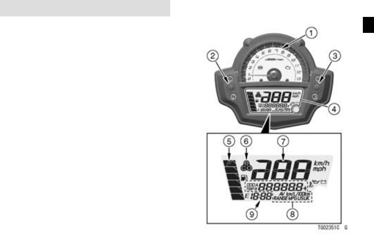
  • Hoe speedometer aanpassen van Miles naar kilometers Gesteld op 11-2-2022 om 18:45

    Reageer op deze vraag Misbruik melden
  • Beste motorrijders. Ik rij een kawasaki 650 versys 2019.
    Afgelopen week heb ik een korte kentekenplaat houder gemonteerd + de originele knipperlichten. Nu passen de zijkoffers niet meer. (Knipperlichten zijn te lang) heeft iemand een oplossing. Grt Hans Gesteld op 2-8-2020 om 11:13

    Reageer op deze vraag Misbruik melden
  • Hoe verwijder ik de zijkappen van mijn versys 650 uit 2018 ik wil graag een radiator beschermer plaatsen maar kan niet bij het
    Gesteld op 3-11-2018 om 16:15

    Reageer op deze vraag Misbruik melden
  • Hallo ik heb ook een radiator beschermer geplaatst maar daarvoor hoefde ik de zijkappen niet te verwijderen goed gereedschap is het halve werk Geantwoord op 11-11-2020 om 12:01

    Waardeer dit antwoord (1) Misbruik melden
  • Heb hem ook geplaats zonder de kappen te verwijderen Geantwoord op 5-11-2023 om 13:15

    Waardeer dit antwoord (1) Misbruik melden

Misbruik melden

Gebruikershandleiding.com neemt misbruik van zijn services uitermate serieus. U kunt hieronder aangeven waarom deze vraag ongepast is. Wij controleren de vraag en zonodig wordt deze verwijderd.

Product:

Bijvoorbeeld antisemitische inhoud, racistische inhoud, of materiaal dat gewelddadige fysieke handelingen tot gevolg kan hebben.

Bijvoorbeeld een creditcardnummer, een persoonlijk identificatienummer, of een geheim adres. E-mailadressen en volledige namen worden niet als privégegevens beschouwd.

Spelregels forum

Om tot zinvolle vragen te komen hanteren wij de volgende spelregels:

Belangrijk! Als er een antwoord wordt gegeven op uw vraag, dan is het voor de gever van het antwoord nuttig om te weten als u er wel (of niet) mee geholpen bent! Wij vragen u dus ook te reageren op een antwoord.

Belangrijk! Antwoorden worden ook per e-mail naar abonnees gestuurd. Laat uw emailadres achter op deze site, zodat u op de hoogte blijft. U krijgt dan ook andere vragen en antwoorden te zien.

Abonneren

Abonneer u voor het ontvangen van emails voor uw Kawasaki Versys 650 bij:


U ontvangt een email met instructies om u voor één of beide opties in te schrijven.


Ontvang uw handleiding per email

Vul uw emailadres in en ontvang de handleiding van Kawasaki Versys 650 in de taal/talen: Engels als bijlage per email.

De handleiding is 1,95 mb groot.


U ontvangt de handleiding per email binnen enkele minuten. Als u geen email heeft ontvangen, dan heeft u waarschijnlijk een verkeerd emailadres ingevuld of is uw mailbox te vol. Daarnaast kan het zijn dat uw internetprovider een maximum heeft aan de grootte per email. Omdat hier een handleiding wordt meegestuurd, kan het voorkomen dat de email groter is dan toegestaan bij uw provider.

Stel vragen via chat aan uw handleiding

Stel uw vraag over deze PDF

Uw handleiding is per email verstuurd. Controleer uw email

Als u niet binnen een kwartier uw email met handleiding ontvangen heeft, kan het zijn dat u een verkeerd emailadres heeft ingevuld of dat uw emailprovider een maximum grootte per email heeft ingesteld die kleiner is dan de grootte van de handleiding.

Er is een email naar u verstuurd om uw inschrijving definitief te maken.

Controleer uw email en volg de aanwijzingen op om uw inschrijving definitief te maken

U heeft geen emailadres opgegeven

Als u de handleiding per email wilt ontvangen, vul dan een geldig emailadres in.

Uw vraag is op deze pagina toegevoegd

Wilt u een email ontvangen bij een antwoord en/of nieuwe vragen? Vul dan hier uw emailadres in.


Info