FOREWORD ............................................. i
IMPORTANT .............................................. i
IN CASE OF EMERGENCY ...................... ii
NOTE ........................................................ ii
RADIO OPERATOR WARNING ............... iii
TABLE OF CONTENTS ........................... iv
PRECAUTION .......................................... v
EXPLICIT DEFINITIONS .......................... v
1 OPERATING RULES .................. 1
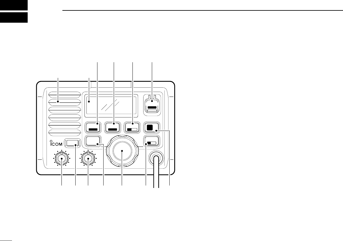
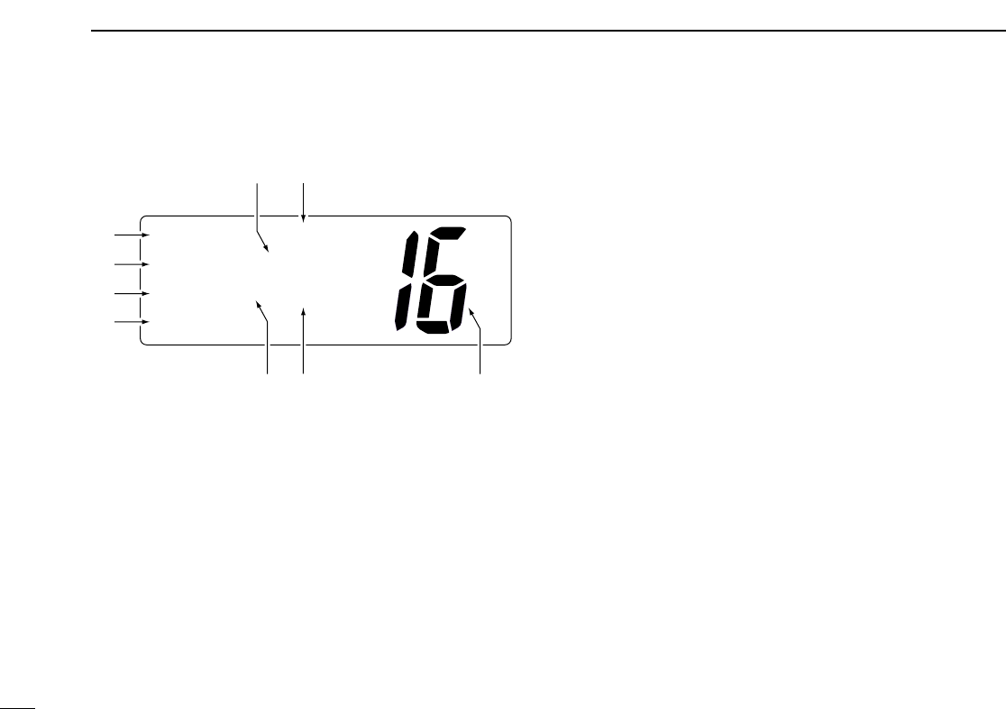
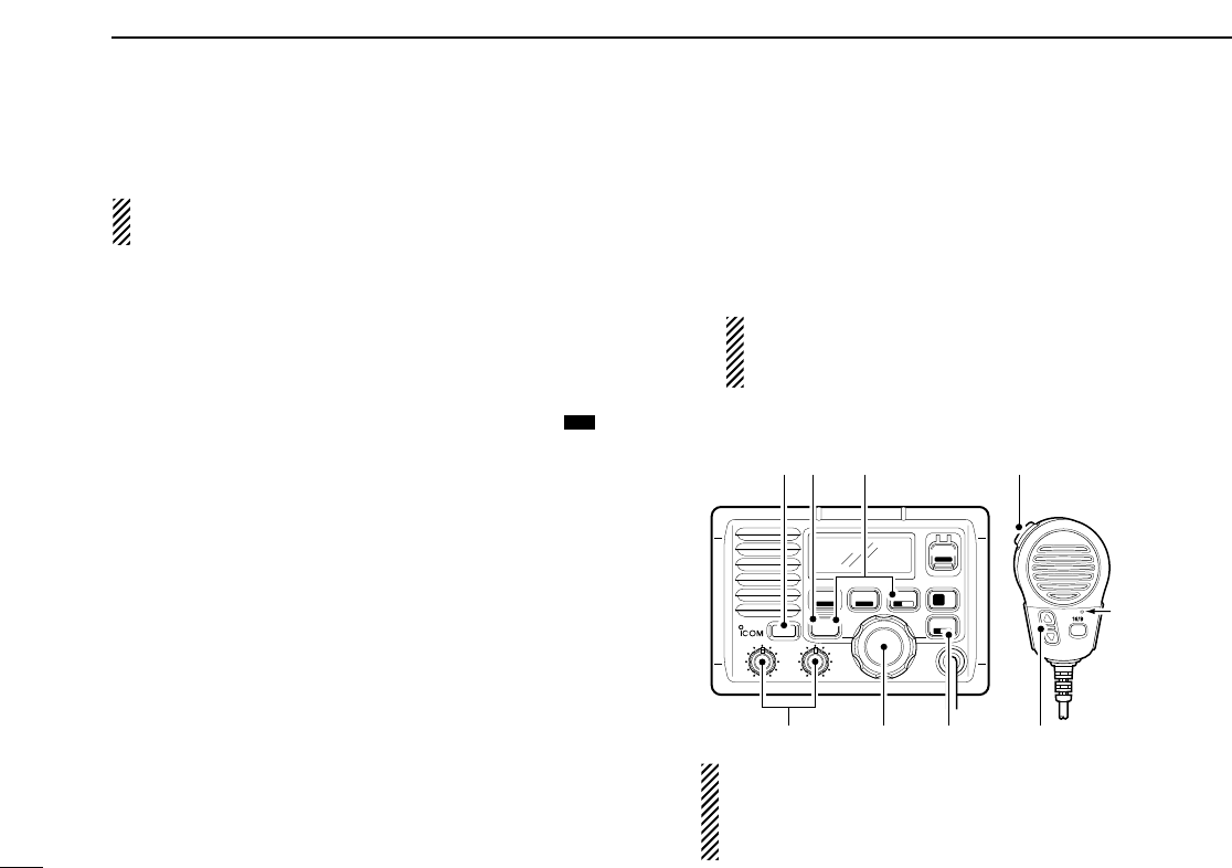
2 PANEL DESCRIPTION........... 2 –5
■ Front panel ..................................... 2
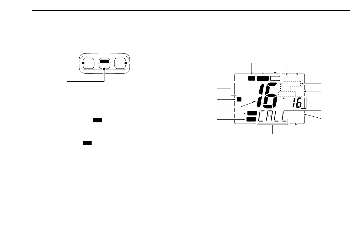
■ Function display .............................. 4
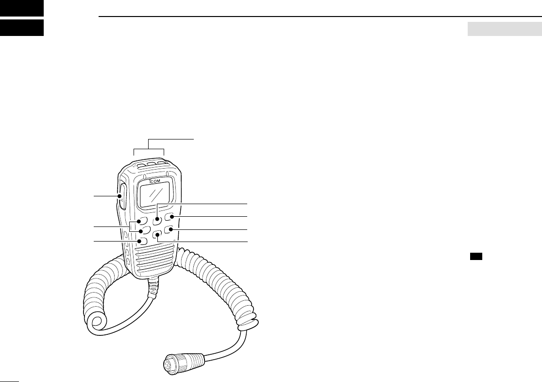
■ Microphone...................................... 5
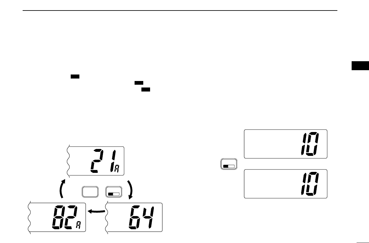
3 BASIC OPERATION ............ 6–10
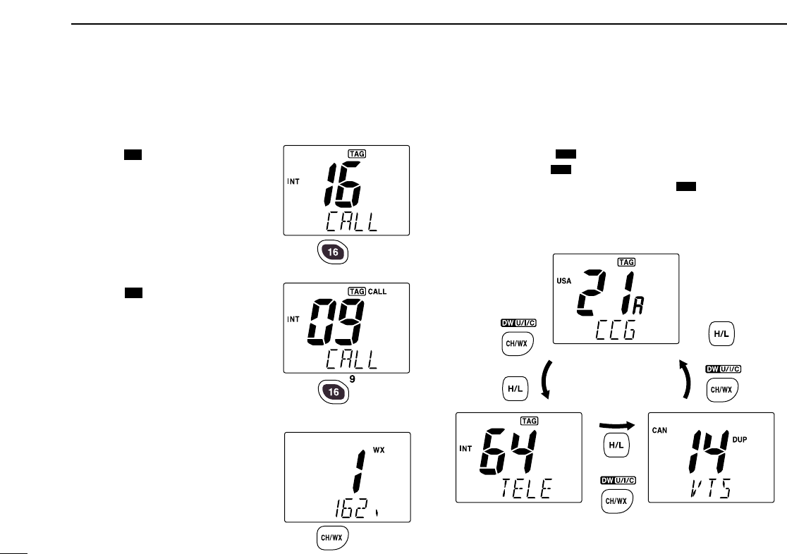
■ Channel selection ........................... 6
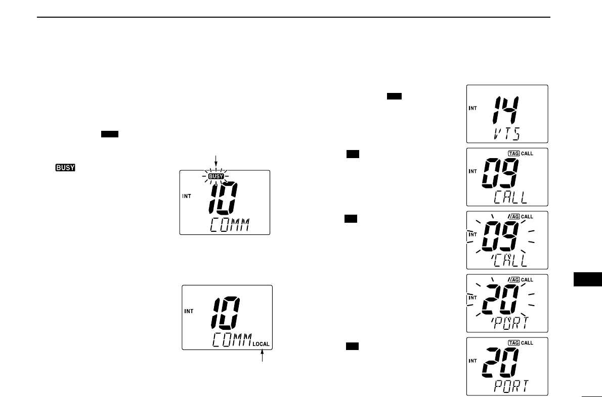
■ Receiving and transmitting ............. 8
■ Call channel programming .............. 9
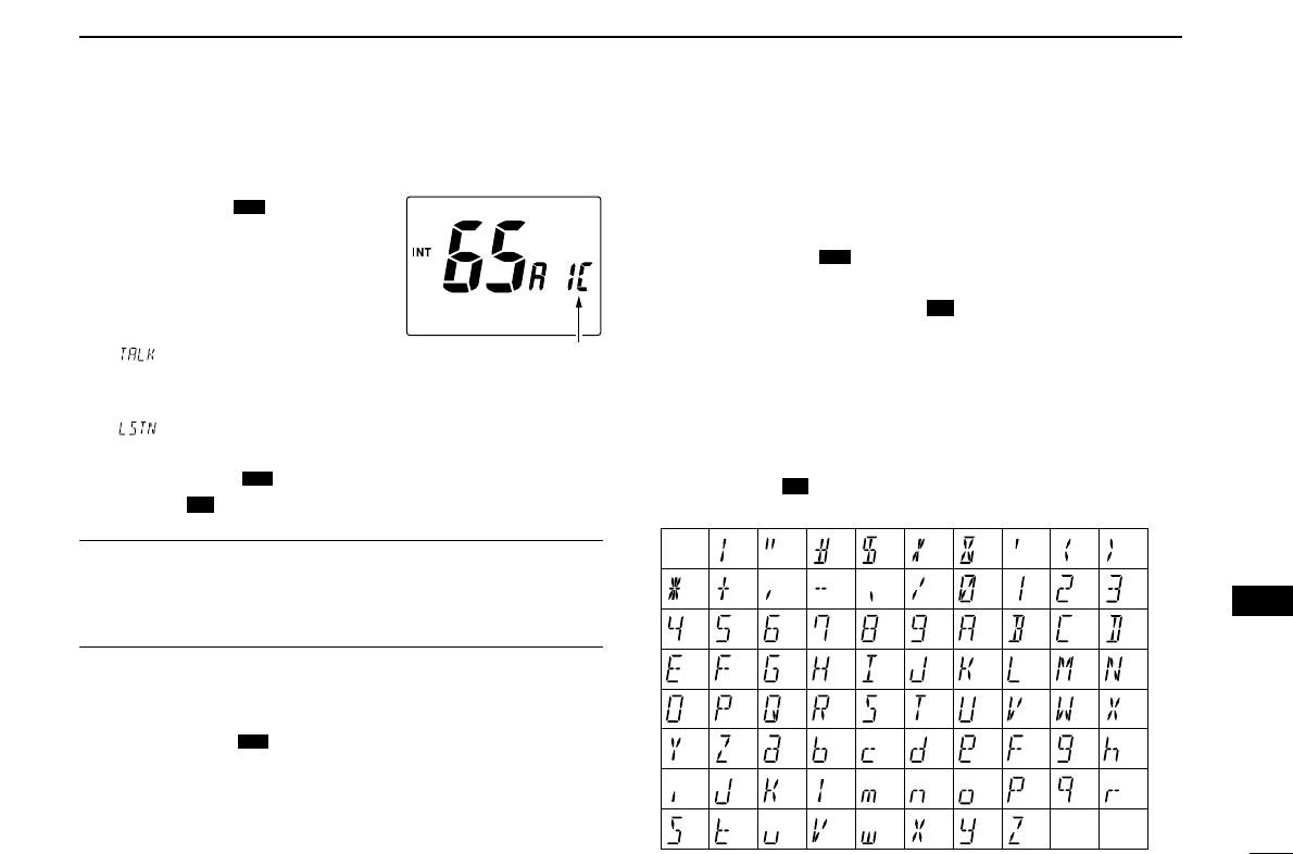
■ Channel comments ......................... 9
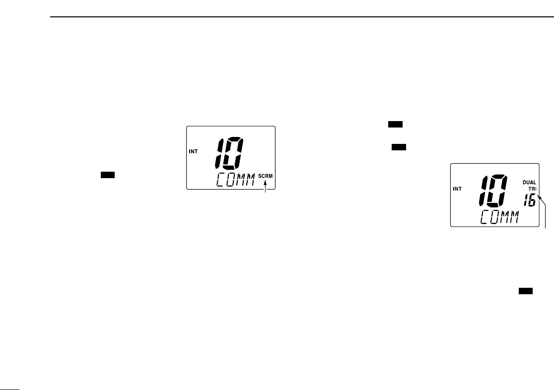
■
Optional Voice scrambler operation .. 10
4
DUALWATCH/TRI-WATCH
......... 11
■ Description .................................... 11
■ Operation ...................................... 11
5 SCAN OPERATION ........... 12 –13
■ Scan types .................................... 12
■ Setting tag channels ..................... 13
■ Starting a scan .............................. 13
6 DSC OPERATION .............. 14 –35
■ MMSI code programming ............. 14
■ DSC individual ID ......................... 14
■ Position and Time programming ... 16
■ Position/Time indication ................ 17
■ Distress call .................................. 18
■ Transmitting DSC calls ................. 21
■ Receiving DSC calls ..................... 29
■ Received messages ..................... 32
■ DSC Set mode .............................. 34
7 OTHER FUNCTIONS .......... 36–37
■ Intercom operation ........................ 36
■ Microphone lock function .............. 37
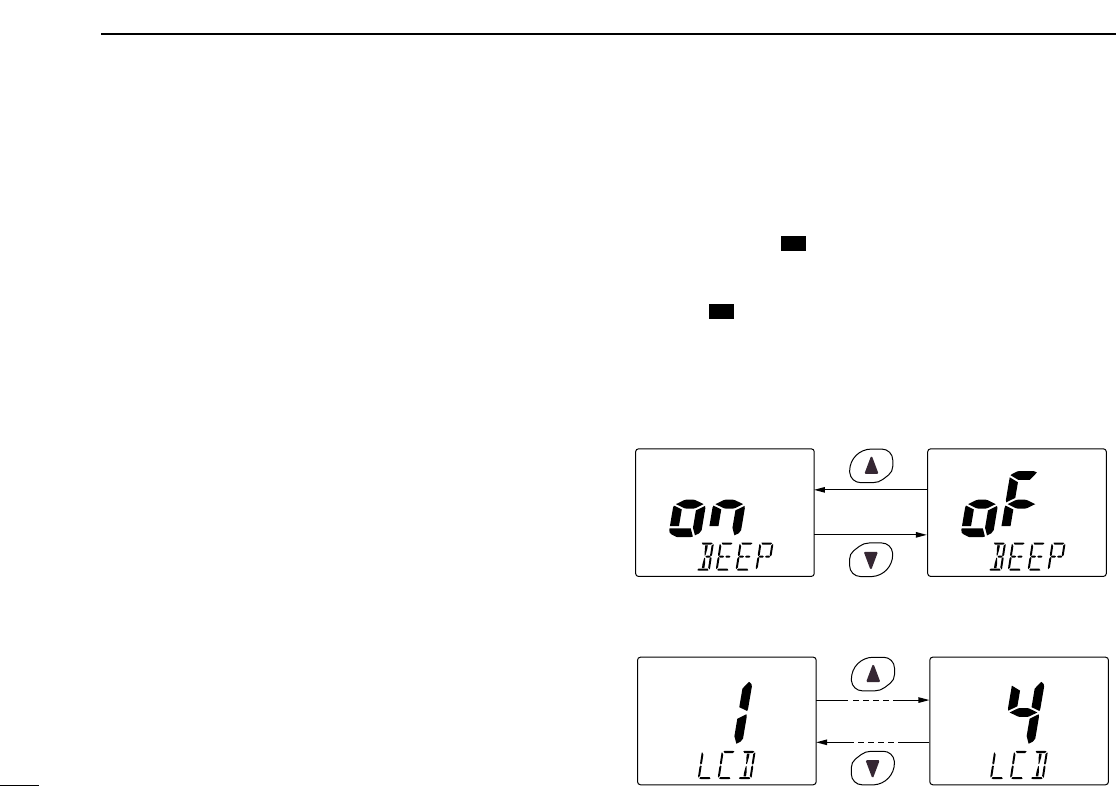
8 SET MODE ........................ 38– 41
■ Set mode programming ................ 38
■ Set mode items ............................. 39
9 CONNECTIONS AND
MAINTENANCE ................. 42 – 47
■ Supplied accessories .................... 42
■ Antenna ........................................ 42
■ Fuse replacement ......................... 42
■ Cleaning ....................................... 42
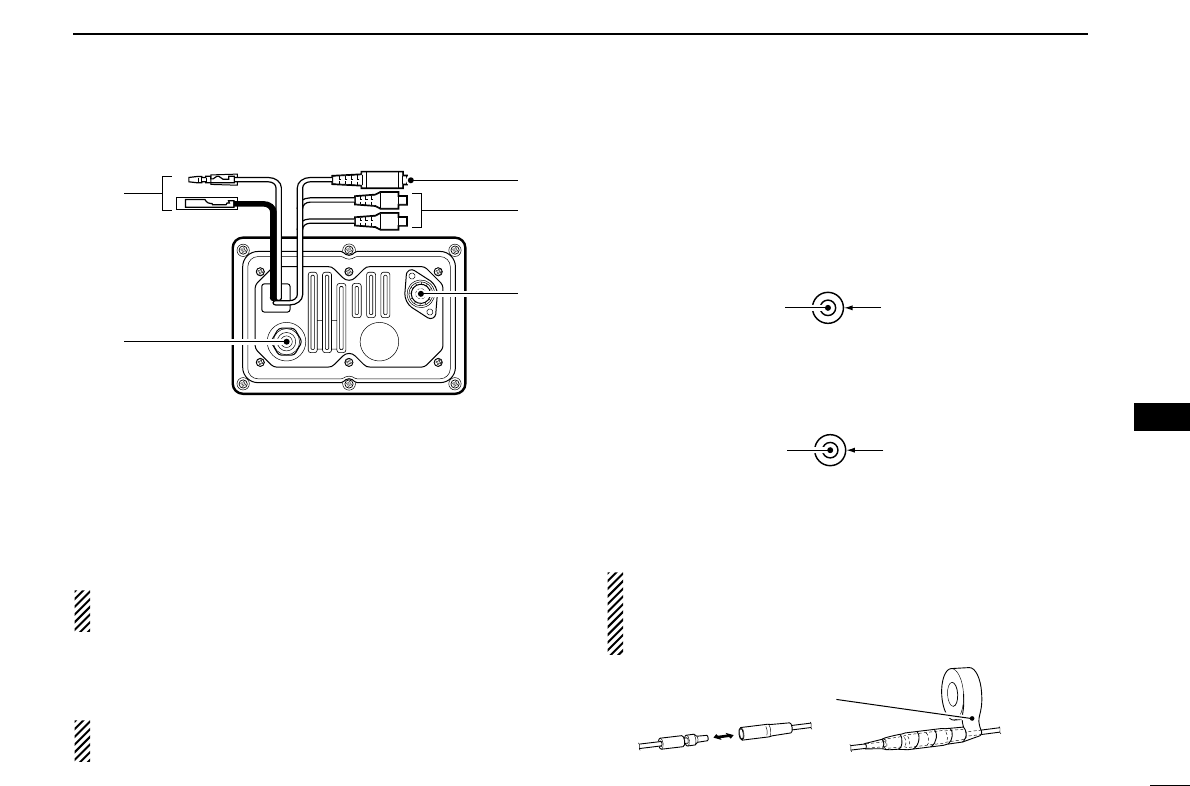
■ Connections .................................. 43
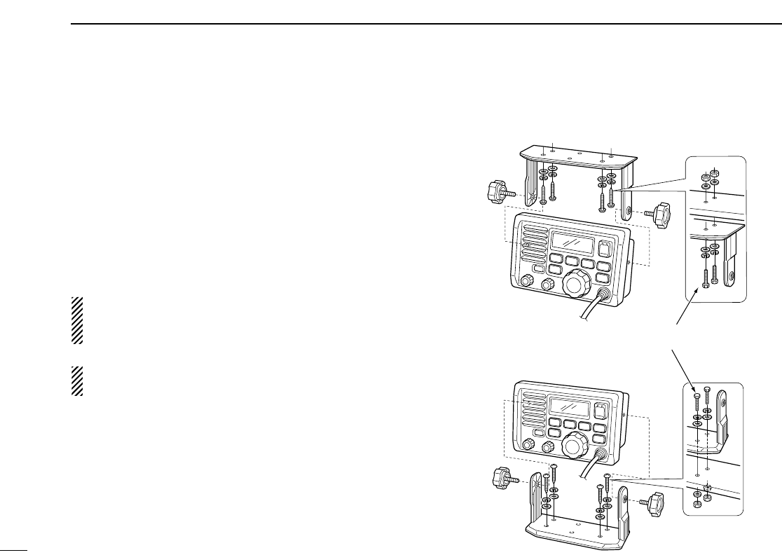
■ Mounting the transceiver .............. 44
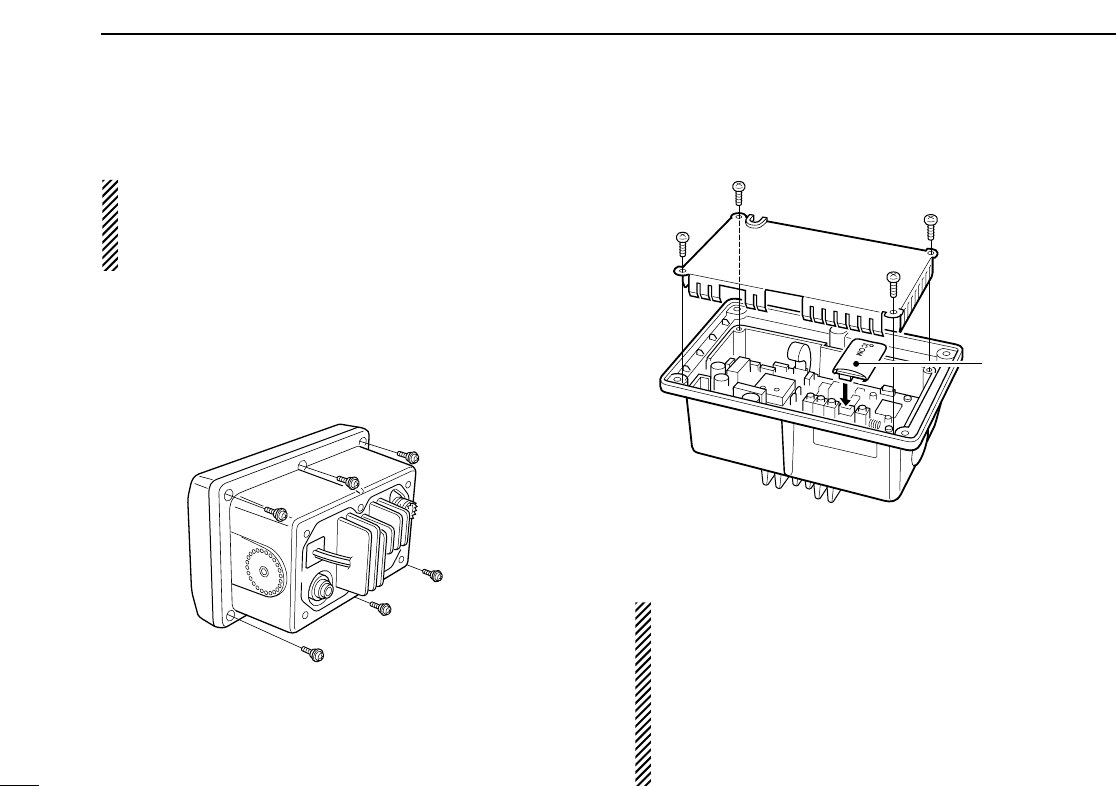
■ Optional unit installation ............... 46
■ Dimensions ................................... 47
10 TROUBLESHOOTING .............. 48
11 CHANNEL LIST ........................ 49
12 SPECIFICATIONS AND
OPTIONS ........................... 50 – 51
■ Specifications ............................... 50
■ Options ......................................... 51
13 HM-127 REMOTE-CONTROL
MICROPHONE ................... 52 – 66
■ Panel description .......................... 52
■ Function display ............................ 54
■ Channel selection ......................... 56
■ Receiving and transmitting ........... 57
■ Lock functions ............................... 58
■ Display backlighting ...................... 58
■ Monitor function ............................ 59
■ RF attenuator function .................. 59
■ Call channel programming ............ 59
■
Optional Voice scrambler operation .. 60
■ Dualwatch/Tri-watch operation ..... 60
■ Starting a scan .............................. 61
■ Setting tag channels ..................... 61
■ Set mode programming ................ 62
■ Intercom operation ........................ 63
■ Channel comments ....................... 63
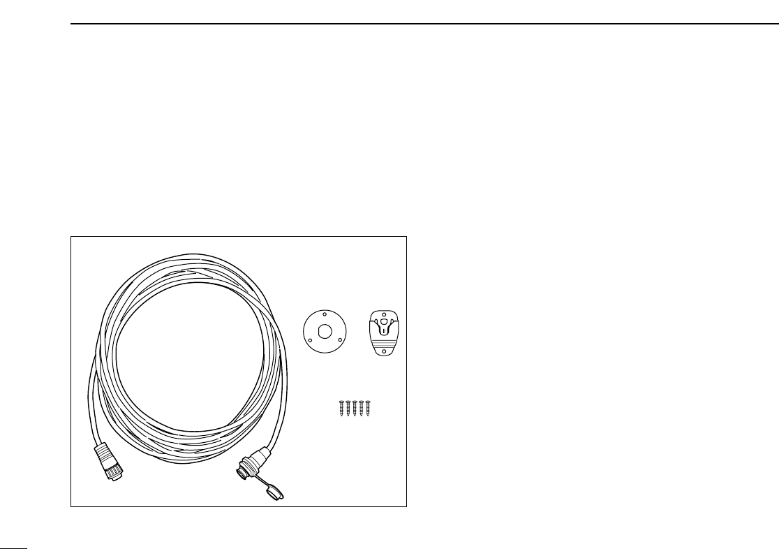
■ HM-127 supplied accessories ...... 64
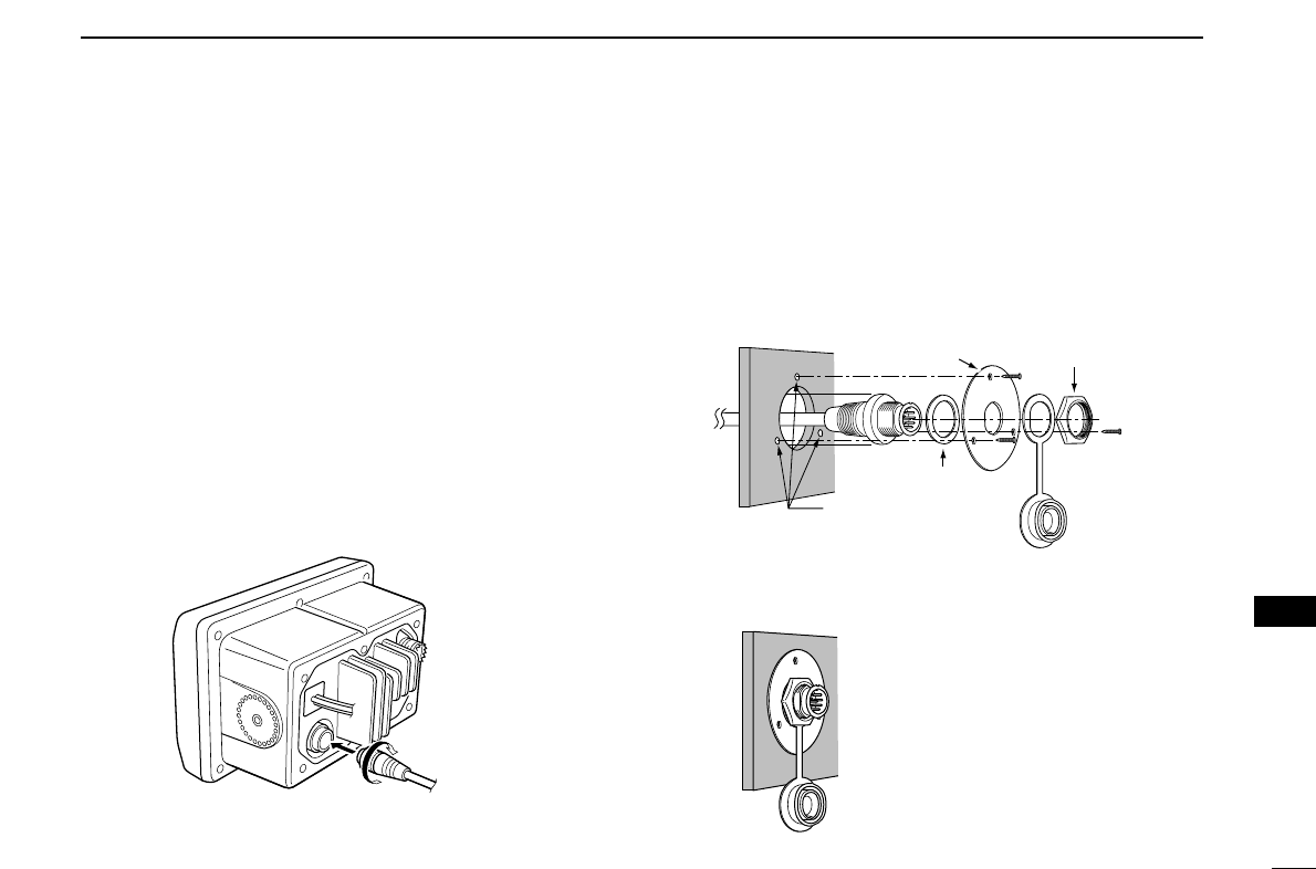
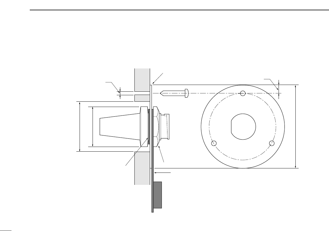
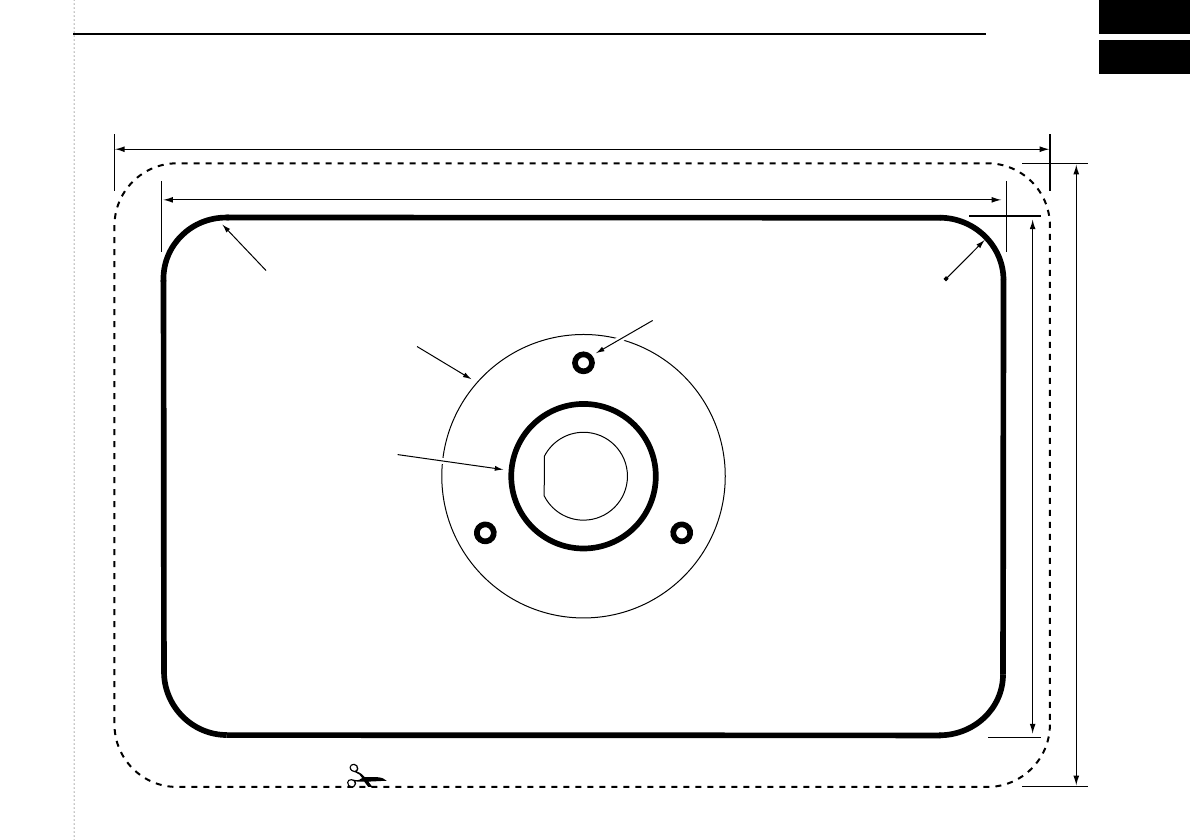
■ Installation .................................... 65
TEMPLATE
iv
TABLE OF CONTENTS
1
2
3
4
5
6
7
8
9
10
11
12
13