670468
37
Verklein
Vergroot
Pagina terug
1/192
Pagina verder
COMMUNICATIONS RECEIVER
iR9500
Instruction Manual
A-6553H-1EX
Printed in Japan
© 2007 Icom Inc.
i
FOREWORD
Thank you for making the IC-R9500 your radio of choice. We hope you
agree with Icom’s philosophy of “technology first.” Many hours of research
and development went into the design of your IC-R9500.
D
FEATURES
Ultimate receiver performance: 109 dB wide dynamic range
and third-order intercept (IP3) of +40 dBm (HF bands only)
7-inch wide color TFT LCD
Built-in Baudot FSK demodulator
High resolution spectrum scope— center frequency and fix
frequency modes, plus mini-scope displays
IMPORTANT
READ THIS INSTRUCTION MANUAL CAREFULLY before at-
tempting to operate the receiver.
SAVE THIS INSTRUCTION MANUAL. This manual contains im-
portant safety and operating instructions for the IC-R9500.
EXPLICIT DEFINITIONS
TRADEMARKS
Icom, Icom Inc. and the logo are registered trademarks of Icom
Incorporated (Japan) in the United States, the United Kingdom, Germany,
France, Spain, Russia and/or other countries.
WORD DEFINITION
RR
WARNING
Personal injury, fire hazard or electric shock may
occur.
CAUTION Equipment damage may occur.
NOTE
If disregarded, inconvenience only. No risk of person-
al injury, fire or electric shock.
ABOUT RE-EXPORTING THIS PRODUCT:
If re-exporting this product, it is your responsibility to check you are in compliance with the export regulations
of your country or the country you are exporting to. Export regulations can be highly restrictive in relation to
some of the technology implemented in this product. Your failure to comply with export regulations may sub-
ject you to fines or penalties. Please consult with the relevant Government Department in your country.
ii
PRECAUTIONS
R WARNING! NEVER operate the receiver with a
headset or other audio accessories at high volume
levels. Hearing experts advise against continuous high
volume operation. If you experience a ringing in your
ears, reduce the volume or discontinue use.
R CAUTION! NEVER change the internal set-
tings of the receiver. This may reduce receiver perfor-
mance and/or damage to the receiver.
The receiver warranty does not cover any problems
caused by unauthorized internal adjustment.
R CAUTION! The receiver weighs approx. 20 kg
(44 lb). Always have two people available to carry, lift
or turn over the receiver.
R CAUTION! The line-voltage receptacle must be
near the receiver and must be easily accessible. Avoid
extension cords.
R ACHTUNG! Die Steckdose muß nabe bei
diesem Gerät angebracht und zugänglich sein.
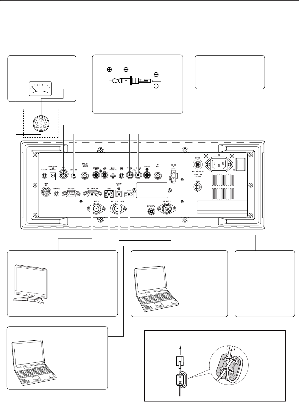
R NEVER let metal, wire or other objects protrude
into the receiver or into connectors on the rear panel.
This may result in an electric shock.
R NEVER block any cooling vents on the top, rear
or bottom of the receiver.
R NEVER expose the receiver to rain, snow or any
liquids.
R NEVER install the receiver in a place without ad-
equate ventilation. Heat dissipation may be reduced,
and the receiver may be damaged.
R NEVER operate or touch the receiver with wet
hands. This may result in an electric shock or damage
to the receiver.
DO NOT
use chemical agents such as benzine or al-
cohol when cleaning the IC-R9500, as they can dam-
age the receivers surfaces.
AVOID using or storing the receiver in areas with tem-
peratures below ±0°C (+32°F) or above +50°C
(+122°F).
AVOID placing the receiver in excessively dusty envi-
ronments or in direct sunlight.
AVOID placing the receiver against walls or putting
anything on top of the receiver. This may overheat the
receiver.
Always place unit in a secure place to avoid inadver-
tent use by children.
The LCD display may have cosmetic imperfections that
appear as small dark or light spots. This is not a mal-
function or defect, but a normal characteristic of LCD
displays.
During maritime mobile operation, keep the receiver as
far away as possible from the magnetic navigation
compass to prevent erroneous indications.
Turn [I/O] switch (on the rear panel) OFF and/or dis-
connect the AC power cable from the AC outlet when
you will not use the receiver for a long period of time.
For U.S.A. only
CAUTION: Changes or modifications to this device,
not expressly approved by Icom Inc., could void your
authority to operate this device under FCC regulations.
ABOUT APCO PROJECT 25
This device made under license under one or more of
the following US patents: #4,590,473, #4,636,791,
#5,148,482, #5,185,796, #5,271,017, #5,377,229.
The IMBE™ voice coding technology embodied in this
product is protected by intellectual property rights
including patent rights, copyrights and trade secrets of
Digital Voice Systems, Inc. This voice coding
Technology is licensed solely for use within this com-
munications equipment. The user of this technology is
explicitly prohibited from attempting to decompile,
reverse engineer, or disassemble the object code, or
in any other way convert the object code into a
human-readable form. U.S. Pat. nos. #5,870,405,
#5,826,222, #5,754,974, #5,701,390, #5,715,365,
#5,649,050, #5,630,011, #5,581,656, #5,517,511,
#5,491,772, #5,247,579, #5,226,084, #5,195,166.
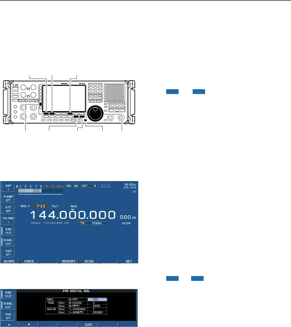
P25 digital mode is available when the optional
UT-122
DIGITAL UNIT is installed.
q AC power cable* ………………………………… 1
w Carrying handles ……………………………… 1 set
e Spare fuse (FGB 1 A) …………………………… 1
r Spare fuse
FGB 4 A (100 V/120 V versions) ………………… 1
0234002MXP (230 V/240 V versions)
…………… 1
t RCA plugs ………………………………………… 4
y DC power plug …………………………………… 1
u 2-conductor
1
8 plugs …………………………… 7
i 3-conductor
1
8 plugs …………………………… 1
o 8 pin ACC plugs …………………………………… 2
!0 Screws for side plate
…………………………… 4
!1 Hiding screws for screw hole
…………………… 2
!2 Ferrite bead
……………………………………… 3
*May differ from that shown according to version.
These screw are used when removing rack mounting han-
dles.
These are used when connecting cables to [DATA IN], [LAN]
or [USB].
iii
SUPPLIED ACCESSORIES
q
o
!0
!1
tyu i
e
w
r
(FH M4×16 mm)
(FH M4×12 mm)
(PH M4×8 mm)
PH: Pan head
FH: Flat head
!2
(see p. 2-7 for installation details)
iv
Section 1 PANEL DESCRIPTION
Front panel ……………………………………………………………… 1-2
Rear panel ……………………………………………………………… 1-10
LCD display …………………………………………………………… 1-12
Screen menu arrangement …………………………………………… 1-14
Section 2 INSTALLATION AND CONNECTIONS
Unpacking ……………………………………………………………… 2-2
Selecting a location …………………………………………………… 2-2
Grounding ……………………………………………………………… 2-2
Antenna connection …………………………………………………… 2-3
TV jumper cable connection …………………………………………… 2-4
Carrying handle attachment …………………………………………… 2-4
Rack mounting handle detachment …………………………………… 2-4
Required connections ………………………………………………… 2-5
D Rear panel …………………………………………………………… 2-5
Advanced connections ………………………………………………… 2-6
D Front panel …………………………………………………………… 2-6
D Rear panel—1 ……………………………………………………… 2-6
D Rear panel—2 ……………………………………………………… 2-7
Tape recorder connections …………………………………………… 2-8
D Recording from the front panel or rear panel …………………… 2-8
D Separately recording audio and frequency ……………………… 2-9
Monitor display connection …………………………………………… 2-10
Transceive function …………………………………………………… 2-10
FSK and AFSK (SSTV) connections ………………………………… 2-11
Accessory connector information …………………………………… 2-12
Section 3 BASIC OPERATIONS
When first applying power (CPU resetting) ………………………… 3-2
Initial settings …………………………………………………………… 3-2
Selecting VFO mode …………………………………………………… 3-3
Selecting memory mode ……………………………………………… 3-3
Frequency setting ……………………………………………………… 3-4
D Direct frequency entry with the keypad …………………………… 3-4
D Tuning with the main dial …………………………………………… 3-5
D Selecting a tuning step ……………………………………………… 3-5
D Auto tuning step function …………………………………………… 3-6
D
1
4 tuning step function ……………………………………………… 3-6
Operating mode selection ……………………………………………… 3-7
Volume setting ………………………………………………………… 3-8
RF gain adjustment …………………………………………………… 3-8
Squelch level adjustment ……………………………………………… 3-8
Audio tone adjustment ………………………………………………… 3-9
D Treble level adjustment ……………………………………………… 3-9
D Bass level adjustment ……………………………………………… 3-9
Meter indication selection …………………………………………… 3-10
D Meter type selection ……………………………………………… 3-10
Section 4 RECEIVE MODES
Operating FM …………………………………………………………… 4-2
D Convenient functions for FM …………………………………………4-2
Duplex operation ……………………………………………………… 4-3
D Offset frequency setting ………………………………………………4-3
TABLE OF CONTENTS
Tone/DTCS squelch operation ………………………………………… 4-4
Operating WFM ………………………………………………………… 4-5
D Convenient functions for WFM ………………………………………4-5
Operating AM …………………………………………………………… 4-6
D Convenient functions for AM …………………………………………4-6
Operating SSB ………………………………………………………… 4-7
D Convenient functions for SSB ………………………………………4-7
Operating CW …………………………………………………………… 4-8
D Convenient functions for CW ………………………………………4-8
D APF (Audio Peak Filter) operation …………………………………4-9
D About CW reverse mode ……………………………………………4-9
D About CW pitch control ………………………………………………4-9
Operating FSK ………………………………………………………… 4-10
D Convenient functions for FSK ………………………………………4-11
D About FSK reverse mode …………………………………………4-11
D Twin peak filter ………………………………………………………4-11
D Setting FSK tone frequency ………………………………………4-12
D Functions for the FSK decoder indication …………………………4-13
D Setting the decoder threshold level ………………………………4-13
D FSK decode set mode ………………………………………………4-14
D Setting FSK Baud rate ………………………………………………4-16
D Time stamp function …………………………………………………4-16
D Data saving …………………………………………………………4-17
Operating P25 (Requires optional UT-122) ………………………… 4-18
D Convenient functions for P25 ………………………………………4-18
Digital squelch operation ……………………………………………… 4-19
TV channel operation (except for USA version) …………………… 4-20
D Convenient functions for TV operation ……………………………4-20
Section 5 RECEIVE FUNCTIONS
Spectrum scope screen ……………………………………………… 5-2
D Center mode ………………………………………………………… 5-2
D Fix mode ……………………………………………………………… 5-3
D Peak marker function ……………………………………………… 5-4
D Wide band-pass filter selection……………………………………… 5-5
D Wide band scope function …………………………………………… 5-5
D Mini scope screen indication ……………………………………… 5-6
D Scope set mode ……………………………………………………… 5-6
Preamplifier ……………………………………………………………… 5-9
Attenuator ……………………………………………………………… 5-9
AGC function …………………………………………………………… 5-10
D Selecting the preset value …………………………………………5-10
D Adjusting the AGC time constant …………………………………5-10
D Setting the AGC time constant preset value ……………………5-10
Twin PBT operation …………………………………………………… 5-11
IF filter selection ……………………………………………………… 5-12
D IF filter selection …………………………………………………… 5-12
D Filter passband width setting ……………………………………… 5-12
D Roofing filter selection ……………………………………………… 5-13
D DSP filter shape …………………………………………………… 5-13
D Filter shape set mode ……………………………………………… 5-13
Noise blanker ………………………………………………………… 5-15
D NB set mode ………………………………………………………… 5-15
v
TABLE OF CONTENTS
vi
Noise reduction ………………………………………………………… 5-16
Notch function ………………………………………………………… 5-16
Autotune function ……………………………………………………… 5-17
AFC function …………………………………………………………… 5-17
Section 6 VOICE RECORDER FUNCTIONS
About digital voice recorder …………………………………………… 6-2
Recording a received audio …………………………………………… 6-3
D Regular recording …………………………………………………… 6-3
Playing the recorded audio …………………………………………… 6-4
D Regular playing ……………………………………………………… 6-4
Erasing the recorded contents ………………………………………… 6-4
Selecting the CF memory card or USB-Memory …………………… 6-4
Short recording ………………………………………………………… 6-5
D Recording …………………………………………………………… 6-5
D Playing back ………………………………………………………… 6-5
Voice set mode ………………………………………………………… 6-6
Section 7 MEMORY OPERATION
Memory channels ……………………………………………………… 7-2
Memory channel selection …………………………………………… 7-3
D Using the [M-CH]/[BANK] selectors ……………………………… 7-3
D Using the keypad …………………………………………………… 7-3
Memory channel programming ……………………………………… 7-4
D Programming in VFO mode ………………………………………… 7-4
D Programming in memory mode …………………………………… 7-4
Frequency transferring ………………………………………………… 7-5
D Transferring in VFO mode ………………………………………… 7-5
D Transferring in memory mode ……………………………………… 7-5
Memory names ………………………………………………………… 7-6
D Editing (programming) memory names …………………………… 7-6
Memory clearing ………………………………………………………… 7-6
Memory list screen ……………………………………………………… 7-7
D Selecting a memory channel using the memory list screen …… 7-7
D Confirming programmed memory channels ……………………… 7-7
D Memory bank set …………………………………………………… 7-8
Section 8 SCANS
Scan types ……………………………………………………………… 8-2
Preparation ……………………………………………………………… 8-3
Voice squelch control function ………………………………………… 8-3
Scan set mode ………………………………………………………… 8-4
Priority scan ……………………………………………………………… 8-5
D Setting ………………………………………………………………… 8-5
D Priority scan operation ……………………………………………… 8-5
Programmed scan ……………………………………………………… 8-6
D Setting ………………………………………………………………… 8-6
D Program scan operation …………………………………………… 8-7
F scan ………………………………………………………………… 8-8
D Setting ………………………………………………………………… 8-8
D F scan operation …………………………………………………… 8-8
Fine programmed scan/fine F scan operation……………………… 8-9
Auto memory write scan operation…………………………………… 8-10
TABLE OF CONTENTS
Memory scan …………………………………………………………… 8-11
D Setting ……………………………………………………………… 8-11
D Memory scan operation …………………………………………… 8-11
D Programming the select memory scan setting ………………… 8-12
D Select memory scan operation …………………………………… 8-13
D Mode select memory scan operation …………………………… 8-14
Skip scan ……………………………………………………………… 8-15
D Specifying skip channels ………………………………………… 8-15
D Programming skip frequencies (for programming scan) ……… 8-15
D Skip scan setting …………………………………………………… 8-15
Tone scan ……………………………………………………………… 8-16
Scan resume condition………………………………………………… 8-17
Scan speed …………………………………………………………… 8-18
Scan delay ……………………………………………………………… 8-18
Section 9 OTHER FUNCTIONS
Voice synthesizer operation …………………………………………… 9-2
Lock function …………………………………………………………… 9-2
D Dial lock function ……………………………………………………… 9-2
D Panel lock function …………………………………………………… 9-2
Dial click function ……………………………………………………… 9-3
Antenna selection ……………………………………………………… 9-3
Section 10 CLOCK AND TIMERS
Time set mode ………………………………………………………… 10-2
Daily timer setting …………………………………………………… 10-3
Setting sleep timer …………………………………………………… 10-4
Timer operation ………………………………………………………… 10-4
Section 11 SET MODE
Set mode description ………………………………………………… 11-2
D Set mode operation ………………………………………………… 11-2
D Screen arrangement ……………………………………………… 11-3
Level set mode ………………………………………………………… 11-4
ACC set mode ………………………………………………………… 11-7
Display set mode ……………………………………………………… 11-8
Others set mode ……………………………………………………… 11-10
CF card/USB-Memory set menu …………………………………… 11-16
D CF/USB-Memory set screen arrangement …………………… 11-16
D Load option set mode …………………………………………… 11-17
File saving …………………………………………………………… 11-18
File loading …………………………………………………………… 11-19
Changing the file name ……………………………………………… 11-20
File copying …………………………………………………………… 11-21
Deleting a file ………………………………………………………… 11-22
Unmount an USB-Memory ………………………………………… 11-22
Formatting the CF card or USB-Memory ………………………… 11-23
Display set (Video) mode …………………………………………… 11-24
LCD set mode ………………………………………………………… 11-26
Section 12 MAINTENANCE
Troubleshooting ……………………………………………………… 12-2
D Receiver power …………………………………………………… 12-2
D Receiving …………………………………………………………… 12-2
vii
TABLE OF CONTENTS
viii
D Scanning …………………………………………………………… 12-3
D Display ……………………………………………………………… 12-3
D Voice recorder ……………………………………………………… 12-3
D Format memory media …………………………………………… 12-3
Screen type selection ………………………………………………… 12-4
Main dial brake adjustment ………………………………………… 12-4
Frequency calibration (approximate) ……………………………… 12-5
Opening the receiver’s case ………………………………………… 12-6
Opening the shield case ……………………………………………… 12-6
UT-122 installation …………………………………………………… 12-7
Clock backup battery replacement ………………………………… 12-7
Fuse replacement …………………………………………………… 12-8
D AC power input fuse ……………………………………………… 12-8
D DC output fuse ……………………………………………………… 12-8
Resetting the CPU …………………………………………………… 12-9
Screen Saver Function ……………………………………………… 12-9
Section 13 CONTROL COMMAND
Remote interface (CI-V) information ………………………………… 13-2
D CI-V connection example ………………………………………… 13-2
D Data format ………………………………………………………… 13-2
D Command table …………………………………………………… 13-3
D To send/read memory contents ………………………………… 13-10
D Codes for memory name, bank name, opening message,
and clock 2 name contents ……………………………………… 13-10
D Offset frequency setting ………………………………………… 13-10
D Tone squelch frequency setting ………………………………… 13-10
D DTCS squelch code setting ……………………………………… 13-10
D NAC squelch code setting ……………………………………… 13-11
D Selective squelch code settings ………………………………… 13-11
D Color setting ……………………………………………………… 13-11
D Data mode with filter width setting ……………………………… 13-11
Section 14 SPECIFICATIONS AND OPTIONS
Specifications ………………………………………………………… 14-2
D General ……………………………………………………………… 14-2
D Receiver …………………………………………………………… 14-3
Options ………………………………………………………………… 14-4
Section 15 UPDATING THE FIRMWARE
General ………………………………………………………………… 15-2
Caution ………………………………………………………………… 15-2
Preparation …………………………………………………………… 15-3
D Firmware and firm utility …………………………………………… 15-3
D File downloading …………………………………………………… 15-3
Firmware update— CF memory card ……………………………… 15-4
Firmware update— PC ……………………………………………… 15-6
D Connections ………………………………………………………… 15-6
D IP address setting ………………………………………………… 15-7
D Updating from the PC ……………………………………………… 15-8
TABLE OF CONTENTS
1-1
PANEL DESCRIPTION Section
1
Front panel ……………………………………………………………… 1-2
Rear panel ……………………………………………………………… 1-10
LCD display …………………………………………………………… 1-12
Screen menu arrangement …………………………………………… 1-14
1-2
q POWER SWITCH [POWER] (p. 3-2)
Push to turn the receiver power ON.
The [POWER] indicator above this switch lights green
when powered ON.
Push for 1 sec. to turn the receiver power OFF.
The [POWER] indicator lights orange when the re-
ceiver is OFF when the internal power supply is
switched ON.
w REMOTE CONTROL SWITCH [LOCAL]
Push to cancel remote control operation from a PC
via a CI-V data.
The [REMOTE] indicator lights orange while in remote
control operation.
When the [REMOTE] indicator lights orange, all dials,
keys or switches other than this switch are disabled.
e PANEL LOCK SWITCH [PANEL LOCK] (p. 9-2)
Push to turn the panel lock function ON or OFF.
The panel lock function locks all dials (depends on
set mode setting on p. 11-10), keys and switches
other than [POWER] and [PANEL LOCK].
The [PANEL LOCK] indicator above this switch lights
green when the panel lock is in use.
The dial lock function is also available.
Push and hold for 1 sec. to turn the panel lock
with display sleep function ON.
Pushing [PANEL LOCK] turns this function OFF.
The [PANEL LOCK] indicator above this switch lights
green and the display turns OFF when the sleep
function is in use.
r TIMER SWITCH [TIMER] (p. 10-3)
Turns the sleep or daily timer function ON or
OFF.
The [TIMER] indicator above this switch lights green
when the timer is in use.
Enters timer set mode when pushed and held for
1 sec.
t RECORDER REMOTE JACK [REC REMOTE]
Controls the operation of a tape recorder for record-
ing. Connects to the REMOTE jack on a tape
recorder.
y RECORDER JACK [REC OUT]
Outputs an audio signal. Connect to the AUX or
LINE IN jack on a tape recorder.
u HEADPHONE JACK [PHONES]
Accepts standard 3.5 (d) mm (
1
8) stereo head-
phones.
Output power: 40 mW with an 8 load.
When headphones are connected, the internal speaker
or connected external speaker does not function.
Turn the internal power supply ON before turning the
unit ON from the front panel. The internal power sup-
ply switch is located on the rear panel. (p. 3-2)
1
PANEL DESCRIPTION
i!0
q
w
e
r
t
y
u
o!1 !2
!3
!4 !5
Front panel
1-3
i SQUELCH CONTROL [SQUELCH] (p. 3-8)
Adjusts the squelch threshold level. The squelch
disables output from the speaker (closed condition)
when no signal is received.
The squelch control is particularly effective for FM or
AM. It is also available for other modes.
•11 to 12 o’clock position is recommended for any set-
ting of the [SQL] control.
o PASSBAND TUNING CONTROLS [TWIN PBT]
(p. 5-11)
Adjusts the IF filter “passband width” via the DSP.
Passband width and shift frequency are shown on the
multifunction display.
Push and hold [PBT CLEAR] for 1 sec. to clear the PBT
settings.
•Variable range is set to half of the IF filter passband
width. 25 Hz steps and 50 Hz steps are available in
SSB, CW and FSK modes.
What is the PBT control?
The PBT function electronically modifies the IF passband
width to reject interference. This receiver uses the DSP cir-
cuit for the PBT function.
!0 PBT CLEAR SWITCH [PBT CLEAR] (p. 5-11)
Push and hold for 1 sec. to clear the PBT settings.
The [PBT CLEAR] indicator above this switch lights
when PBT is in use.
!1 AGC CONTROL [AGC] (p. 5-10)
Adjusts the continuously-variable AGC circuit time
constant.
•To use [AGC] control, push the appropriate band’s
[AGC VR/OFF] ([AGC VR] indicator lights green).
!2 AGC SWITCH [AGC VR/OFF] (p. 5-10)
Push to toggle [AGC] control usage ON or OFF.
Use [AGC] control to set the AGC time constant when
switched ON.
The [AGC VR] indicator above this switch lights
green when the control is ON.
Turns the AGC function OFF when pushed and
held for 1 sec.
!3 AUTO NOTCH SWITCH [ANF] (p. 5-16)
Turns the auto notch function ON or OFF when
pushed in SSB, AM, FM and WFM mode.
•“ ” appears when auto notch is in use.
!4 MANUAL NOTCH SWITCHES
[NOTCH1]/[NOTCH2] (p. 5-16)
Turns the manual notch function ON or OFF
when pushed in SSB, CW, AM and FSK mode.
•“ ” or “ ” appear when manual notch is in
use.
Switches the manual notch characteristics be-
tween wide, middle and narrow when pushed
and held for 1 sec.
What is the notch function?
The notch function eliminates unwanted CW or AM carrier
tones while preserving the desired voice signal. The DSP cir-
cuit automatically adjusts the notch frequency to effectively
eliminate unwanted tones.
!5 MANUAL NOTCH FILTER CONTROLS
[NOTCH1]/[NOTCH2] (p. 5-16)
Varies the “notch” frequency of the manual notch fil-
ter to reject an interfering signal while the manual
notch function is ON.
Notch filter center frequency:
SSB : –1060 Hz to 4040 Hz
CW : CW pitch freq. + 2540 Hz to CW pitch freq.
–2540 Hz
AM : –5100 Hz to 5100 Hz
Higher
frequency
NOTCH1
NOTCH2
Lower
frequency
MN2
MN1
AN
Slow
Fast
Low cutHigh cut Center
–+
(PBT1) (PBT2)
Deep
Deep
S-meter
squelch
Noise squelch
Squelch
is open.
Squelch
threshold
Shallow
Shallow
1
PANEL DESCRIPTION
1-4
!6 NOISE REDUCTION SWITCH [NR] (p. 5-16)
Push to switch the DSP noise reduction ON or OFF.
The [NR] indicator above this switch lights green when
the function is activated.
!7 NOISE BLANKER SWITCH [NB] (p. 5-15)
Selects from noise blanker 1, 2, or OFF when
pushed. The noise blanker reduces pulse-type
noise such as that generated by automobile igni-
tion systems. This function cannot be used for
FM, WFM, P25 modes or non-pulse-type noise.
The [NB] indicator above this switch lights green and
“” or “ ” appears on the display when the
function is activated.
Enters blank-width set mode when pushed and
held for 1 sec.
!8 AUDIO PEAK FILTER/TWIN PEAK FILTER
SWITCH [APF/TPF]
Push to turn the audio peak filter ON or OFF dur-
ing CW mode operation. (p. 4-9)
Push to turn the twin peak filter ON or OFF dur-
ing FSK mode operation. (p. 4-11)
•“ ” appears when audio peak filter is in use.
•“ ” appears when twin peak filter is in use.
During CW mode operation, push and hold for
1 sec. to select the APF passband width from 80,
160 and 320 Hz. (p. 4-9)
!9 NOISE REDUCTION LEVEL CONTROL
[NR LEVEL] (outer control; p. 5-16)
Adjusts the DSP noise reduction level when noise
reduction is in use. Set for maximum readability.
•To use this control, noise reduction must be ON.
@0 NOISE BLANKER CONTROL [NB LEVEL]
(inner control; p. 5-15)
Adjust the noise blanker threshold level.
•To use this control, either noise blanker must be ON.
@1 RF GAIN CONTROL [RF] (outer control; p. 3-8)
Adjusts the RF gain level.
While rotating the RF gain control, you may hear
noise. This comes from the DSP unit and does
not indicate a malfunction.
Sensitivity
increases
Sensitivity
decreases
Deep
Shallow
Increases
Decreases
TPF
APF
NB2NB1
1
PANEL DESCRIPTION
!9
!7
!6
@0
!8
@3
@4
@1
@2
@5
Front panel (continued)
1-5
@2 AF CONTROL [AF] (inner control; p. 3-8)
Varies the audio output level of the speaker or
headphones.
@3 BASS RESPONSE CONTROL [BASS]
(outer control; p. 3-9)
Adjusts the bass response of the audio output.
@4 TREBLE RESPONSE CONTROL [TREBLE]
(inner control; p. 3-9)
Adjusts the treble response of the audio output.
@5 MULTIFUNCTION SWITCHES
Push to select the functions indicated in the LCD
display to the right of these switches.
Functions vary depending on the operating condition.
While operating HF bands, selects the
antenna connector from HF ANT 1, HF
ANT 2 and HF ANT 3 when pushed.
(p. 9-3)
During 30–1150 MHz operation, only ANT 1
is available.
During 1150–3335 MHz operation, only ANT
2 is available.
Turns the antenna control voltage ON
and OFF form [ANT SEL] when pushed
and held for 1 sec. (p. 9-3)
Selects one of 2 receive RF preamps or
bypasses them. (p. 5-9)
HF bands
•“P. AMP1” activates 10 dB preamp.
•“P. AMP2” activates high-gain preamp.
Above 30 MHz bands
Only “P. AMP” is available.
What is the preamp?
The preamp amplifies received signals in the front end cir-
cuit to improve S/N ratio and sensitivity. Select “P. AMP1” or
“P. AMP2” when receiving weak signals.
Selects the attenuator when pushed.
(p. 5-9)
HF bands: 6, 12, 18, 24, 30 dB.
30–1150 MHz: 10, 20, 30 dB.
•1150–3335 MHz: 20 dB only.
Turns OFF the attenuator when pushed
and held for 1 sec. (p. 5-9)
What is the attenuator?
The attenuator prevents a desired signal from distorting
when very strong signals are near the receiving frequency,
or when very strong electric fields, such as from a broad-
casting station, are near your location.
Selects one of 3 IF filter settings.
Enters the filter set screen when pushed
and held for 1 sec.
Activates and selects fast, middle or slow
AGC time constant when pushed.
(p. 5-10)
In FM, WFM or P25 mode, only “FAST” is
available.
“VR (volume)” indicates that AGC time con-
stant depends on [AGC] control.
Enters the AGC set mode when pushed
and held for 1 sec. (p. 5-10)
AGC time constant can be set from 0.1 to 8.0 sec.
(depends on mode), or turned OFF. When AGC is
“OFF,” the S-meter does not function.
What is the AGC?
The AGC controls receiver gain to produce a constant audio
output level, even when the received signal strength varies
dramatically. Select “FAST” for tuning and then select “MID”
or “SLOW” depending on the receiving conditions.
Switches between the tone squelch,
DTCS squelch function and no-tone op-
eration when pushed in FM mode.
(p. 4-4)
Enters the tone set mode when pushed
and held for 1 sec. in FM, FSK mode.
(pgs. 4-4, 4-12)
Push to toggle the CW pitch setting
screen ON and OFF in CW mode.
(p.4-9)
(Requires optional UT-122)
Switches the digital squelch between
NAC squelch, selective squelch and
OFF in P25 mode. (p. 4-19)
Enters the code set mode when pushed
and held for 1 sec. in P25 mode.
(p. 4-19)
Push to switch the voice squelch control
function ON and OFF; useful for scan-
ning. (p. 8-3)
Treble level
increases
Treble level
decreases
Bass level
increases
Bass level
decreases
Audio output
increases
Audio output
decreases
1
PANEL DESCRIPTION
1-6
@6 LCD FUNCTION DISPLAY (p. 1-10)
Shows the operating frequency, function switch
menus, spectrum scope screen, memory channel
screen, set mode settings, etc.
@7 RECEIVE INDICATOR [RECEIVE]
Lights green while receiving a signal and when the
squelch is open.
@8 TUNING STEP SWITCHES [UP]/[DOWM]
(p. 3-5)
Select the tuning step for the main dial. Push
[UP] to select a larger tuning step; push
[DOWN] to select a smaller tuning step.
•1 Hz, 10 Hz, 100 Hz, 1 kHz, 2.5 kHz, 5 kHz, 6.25
kHz, 9 kHz, 10 kHz, 12.5 kHz, 20 kHz, 25 kHz, 100
kHz and 1 MHz are selectable.
Programmable tuning steps can be set between 0.1
and 999.9 kHz in 0.1 kHz steps.
To set programmable tuning steps, enter the de-
sired steps via the keypad, then push [YUP] or
[ZDOWN].
Push and hold [UP] (or [DOWN]) for 1 sec.
to enter the tuning step select screen.
Unwanted tuning step for each operating mode can
be skipped in the tuning step select.
@9 MEMORY TRANSFER SWITCH [M
V] (p. 7-5)
Transfers the memory contents to VFO when
pushed and held for 1 sec.
This function is available both in VFO and memory
modes.
#0 MEMORY SWITCH [MEMO] (p.7-3)
Selects the memory mode when pushed.
After pushing one to three digit (0 to 999), pushing
the switch selects a memory channel.
Memory bank limit function ON or OFF when
pushed and held for 1 sec.
#1 REMOTE CONTROL INDICATOR [REMOTE]
Lights yellow when a command is received from a
PC via CI-V data.
When this indicator lights yellow, all dials, keys or
switches other than [LOCAL] are disabled.
This indicator goes OFF, when [LOCAL] is pushed.
#2 DIAL LOCK INDICATOR [LOCK] (p. 9-2)
Lights orange when the dial lock function is acti-
vated.
1
PANEL DESCRIPTION
$3
@8 #3 #8#0@9 #5 #6 #7 #9 $0#4
@7@6 #1 #2
$1 $2 $4
Front panel (continued)
1-7
#3 VFO SWITCH [VFO]
Selects the VFO mode when pushed. (p. 3-3)
After pushing a digit switch (0 to 9), push this switch se-
lects a VFO mode (VFO-0 to VFO-9).
#4 KEYPAD (pgs. 3-3, 3-4, 7-3)
Enters a frequency or memory channel. Pushing
[ENT], [VFO] or [MEMO] ends keypad input.
e.g. to enter 14.195 MHz, push [1] [4] [•] [1] [9] [5]
[ENT].
#5 ENTER SWITCH [ENT]
Enters input frequency. (pgs. 3-4)
#6 MEMORY WRITE SWITCH [MW] (p. 7-4)
Stores the selected readout frequency and operat-
ing mode into the displayed memory channel when
pushed and held for 1 sec.
This function is available both in VFO and memory
modes.
#7 MEMORY CLEAR SWITCH [M-CL] (p. 7-7)
Push and hold to clear the contents of displayed
memory channel.
#8 SPEAKER
Outputs audio signals.
#9 1/4-SPEED TUNING SWITCH [1/4]
Push to turn the
1
4
-speed tuning function ON or
OFF in CW and FSK modes. (p. 3-6)
•“ ” appears when
1
4 function is in use.
1
4
function sets dial rotation to
1
4
of normal speed
for fine tuning.
Push and hold to turn the dial click function ON
or OFF. (p. 9-3)
$0 AFC/AUTOMATIC TUNING SWITCH
[AFC•AUTOTUNE]
Turns the AFC function ON or OFF in FM or
WFM modes.
•“ ” appears when AFC function is in use.
Turns the automatic tuning function ON or OFF
in AM, SSB and CW modes.
•“ ” blinks when autotune function is acti-
vate.
$1 LCD FUNCTION SWITCHES [F-1]–[F-7]
Push to select the function indicated in the LCD dis-
play above these switches.
Functions vary depending on the operating condition.
$2 MINI SPECTRUM SCOPE SWITCH [M.SCOPE]
(p. 5-6)
Turns the mini spectrum scope screen ON or
OFF.
The mini spectrum scope screen can be displayed
with another screen, such as memory or set mode
screen, simultaneously.
Turns the spectrum scope screen ON when
pushed and held for 1 sec.
$3 MODE SWITCHES
Selects the desired mode. (p. 3-7)
Announces selected mode via the speech synthesizer.
(p. 11-11)
Selects FM mode.
Selects WFM mode.
Selects AM and S-AM modes alternately.
Switches S-AM(D), S-AM(U) and S-
AM(L) mode when pushed and held for
1 sec. in S-AM mode.
Switches between SSB and CW mode.
Switches between LSB and USB mode
when pushed and held for 1 sec. in SSB
mode.
Switches between CW and CW-R
(CW
reverse)
mode when pushed and held for
1 sec. in CW mode.
Selects FSK and FSK-R
(FSK reverse)
modes alternately.
Selects Digital (P25) mode. (Requires
optional UT-122.)
$4 DISPLAY SWITCH [DISPLAY]
Push to toggle the external input screen between
mini video screen, full video screen, or OFF.
If no signal inputs from [VIDEO IN], black screen ap-
pears.
Enter the display set mode menu screen when
pushed and held for 1 sec.
DIGITAL
FSK
SSB/CW
WF
M
IMPORTANT!
When receiving a weak signal, or receiving a
signal with interference, the automatic tuning
function may tune the receiver to an undesired
signal.
AFC
1
4
1
PANEL DESCRIPTION
1-8
$5 DIMMER SWITCH [DIMMER] (p.11-26)
Push to turn the dimmer function ON or OFF.
When this function is ON, LEDs and LCD backlight
become dim according to the preset setting.
Push and hold for 1 sec. to reset the LCD setting
to the default value with the dimmer function ON
and OFF.
$6 LCD SET SWITCH [LCD SET] (p. 11-26)
Push to toggle the LCD setting screen ON or
OFF.
LCD contrast and backlight’s brightness can be set.
$7 DUPLEX SWITCH [DUP] (p. 4-3)
Push to select the duplex function (DUP–, DUP+
and OFF).
Push and hold for 1 sec. to enter the offset fre-
quency set mode.
$8 VOICE MEMORY RECORD SWITCH [REC]
Short recording; Push momentarily to record the
signal received for the preset time period before
[REC] was pushed. (p.6-5)
Starts recording again automatically.
Regular recording; Push and hold for 1 sec. to
record the received signal until recording is
stopped. (p. 6-3)
Push and hold this switch for 1 sec. to stop record-
ing.
$9 SHORT VOICE MEMORY PLAY BACK SWITCH
[PLAY] (p. 6-5)
Plays back the audio previously recorded during
the preset time period when pushed.
Plays back all of the previously recorded audio
when pushed and held for 1 sec.
%0 EXIT/SET SWITCH [EXIT/SET]
Push to exit, or return to the previous screen dur-
ing spectrum scope, memory, scan or set mode
screen display.
Displays set mode menu screen when pushed
and held for 1 sec.
1
PANEL DESCRIPTION
$8
$5 $6 $7
$9 %1
%9
^0
%2 %4 %5 %6%3 %7 %8
%0
Front panel (continued)
1-9
%1 MONITOR SWITCH [MONI] (pgs. 3-8, 4-4, 4-19)
Push and hold to open the squelch manually.
The [MONI] indicator appears on the display.
While pushing and holding this switch, release any
other receiving functions such as the noise blanker
or ANF.
While in a duplex operation, monitor the shifted fre-
quency.
%2 MAIN DIAL
Changes the displayed frequency, selects set mode
setting, etc.
%3 LOCK SWITCH [LOCK] (p. 9-2)
Push to turn the dial lock function ON or OFF.
%4 SPEECH SWITCH [SPCH] (p. 9-2)
Push to announce the S-meter indication and the
selected readout frequency.
The selected operating mode is also announced
when pushed and held for 1 sec.
%5 MEMORY DIAL [M-CH] (inner control; p. 7-3)
Rotate to select the desired memory channel.
Memory channels can be selected both in VFO and
memory modes.
%6 MEMORY BANK DIAL [BANK]
(outer control; p. 7-3)
Rotate to select the desired memory bank.
Memory banks can be selected both in VFO and mem-
ory modes.
%7 SCAN SPEED CONTROL [SPEED]
(inner control; p. 8-18)
Rotate to adjust the scan speed.
%8 SCAN DELAY CONTROL [DELAY]
(outer control; p. 8-18)
Rotate to adjust the desired scan delay time.
This setting is effective when “DELAY” is selected for the
scan resume condition (%6).
Scan delay time is adjustable between 2 sec. to 20 sec.
%9 SCAN RESUME SWITCHES [OFF]/[DELAY]/[]
(p. 8-17)
Push to select a scan resume condition.
The [SCAN RESUME] indicator lights green above the
selected switch.
^0 SCAN START SWITCHES
(pgs. 8-5, 8-7 to 8-11, 8-13, 8-14)
Push to start the desired scan.
1
PANEL DESCRIPTION
1-10
Rear panel
q
EXTERNAL SPEAKER JACK [EXT-SP]
(p. 2-6)
Connects an external speaker (4–8 ), if desired.
w DC OUTPUT JACK [DC OUTPUT] (p. 2-6)
Outputs regulated 15 V DC (approx.) for external
equipment. Connected in parallel with 13.8 V out-
puts of [ACC]. (max. 1 A total)
e ACCESSORY SOCKET [ACC] (p. 2-6)
Enables connection of external equipment such as
an automatic antenna selector, a TNC for data com-
munications, etc.
See p. 2-12 for socket information.
r ANTENNA SELECTOR VOLTAGE OUTPUT
JACK [ANT SEL]
Outputs regulated 13.8 V DC (max. 100 mA) for ex-
ternal preamplifier or antenna selector, etc.
t REFERENCE SIGNAL INPUT/OUTPUT
TERMINAL [REF I/O 10MHz–10dBm]
Inputs/outputs a 10 MHz reference signal.
y SPEECH OUTPUT JACK [SPEECH OUT] (p. 2-9)
Outputs an operating frequency, mode, S-meter in-
dication and time with a synthesized voice when
pushing [SPCH] or scan stopped.
•Turn ON the “REC SPCH” in the others set mode to ac-
tivate this jack when scan stopped. (p. 11-11)
Output level can be adjusted in ACC set mode. (p. 11-7)
u LINE OUTPUT JACK [LINE OUT]
Audio output jack for tape recorder. The fixed audio
output level is set for a tape recorder AUX jack.
i RECORDER REMOTE JACK [REC REMOTE]
Controls the operation of a tape recorder for record-
ing. Connects to the REMOTE jack on a tape
recorder.
o DETECTOR OUTPUT JACK [DET OUT]
Outputs the detector output signal.
!0 VIDEO INPUT JACK [VIDEO IN]
Accepts video signals for display on the LCD moni-
tor when the [DISPLAY] switch is ON.
!1 VIDEO OUTPUT JACK [VIDEO OUT]
Outputs video signals when TV frequencies with
WFM mode are received. The NTSC M, PAL B/G,
PAL I, PAL D and SECAM K system can be ac-
cepted. (No signals come out for USA version.)
!2 SPARE JACK [SPARE] (p. 2-3)
No connection.
!3 IF OUTPUT JACK [IF OUT] (p. 2-3)
Outputs a 10.7 MHz IF signal.
Output level is the same level as an antenna input
signal or below (when the AGC function is activated
or attenuator is ON.)
!4 DC-DC POWER SOCKET [DC-DC IN] (p. 2-6)
Accepts a regulated 13.5 to 15 V DC input. This
socket does not accept voltage from a non-regu-
lated power source such as a vehicle’s battery.
+
_
_
1
PANEL DESCRIPTION
qw e r t yuio!0 !1 !2 !3 !4 !5 !6 !7
@9 @7 @3@4@5@6 !9 !8@0@1@2@8
1-11
!5 FUSE HOLDER [FUSE] (p. 12-8)
Holds a 4 A fuse (100 V/120 V versions) or 2 A fuse
(230 V/240 V versions) for internal AC power sup-
ply protection. Cuts off the AC input when over-cur-
rent occurs.
CAUTION: Always use the correct fuse for AC
input power. Using a fuse rated for a different
input power may damege your house electrical
system or the receiver.
!6 AC POWER SOCKET [AC] (p. 2-5)
Connects the supplied AC power cable to an AC
line-voltage receptacle.
!7 MAIN POWER SWITCH [I/O] (p. 3-2)
Turns the internal power supply ON or OFF.
!8 GROUND TERMINAL [GND] (p. 2-2)
Connect this terminal to a ground to prevent electri-
cal shocks, TVI, BCI and other problems.
!9 HF ANTENNA CONNECTOR 1 [HF ANT 1]
(p. 2-5)
Accepts a 50 antenna for HF bands with a PL-
259 plug connector.
@0 HF ANTENNA CONNECTOR 2 [HF ANT 2]
(p. 2-5)
Accepts a 500 antenna for HF band with an RCA
connector.
@1 USB CONNECTOR [USB]
Connects USB equipment such as a memory
media, hub or keyboard.
@2 S/P DIF OUTPUT TERMINAL [S/P DIF OUT]
(p. 2-7)
Connects external equipment that supports S/P DIF
output.
@3 HF ANTENNA CONNECTOR 3/ANTENNA CON-
NECTOR 1 [ANT 1/HF ANT 3] (p. 2-5)
Accepts a 50 antenna with a Type-N connector.
Covers the HF bands and 30–1150 MHz frequency
range.
@4 ETHERNET CONNECTOR [LAN] (pgs. 2-7, 15-6)
Connects to a PC through a LAN (Local Area Net-
work).
@5 ANTENNA CONNECTOR 2 [ANT 2] (p. 2-5)
Accepts a 50 antenna with a Type-N connector.
Covers the 1150–3335 MHz frequency range.
@6 EXTERNAL DISPLAY TERMINAL
[EXT-DISPLAY] (p. 2-10)
Connects to an external display monitor.
At least 800×600 pixel display is necessary.
@7 RS-232C TERMINAL [RS-232C] (p. 2-6)
Connects to a PC using a D-sub 9-pin RS-232C
cable.
Can be used for remote control of the IC-R9500
without the optional CT-17, or the FSK decoded sig-
nal output. The [RS-232C] interface is wired as a
modem (DCE).
@8 CI-V REMOTE CONTROL JACK [REMOTE]
(p. 2-6)
Connects a PC via the optional CT-17
CI-V LEVEL
CONVERTER for external control of the receiver.
Used for transceive operation with another Icom
CI-V transceiver or receiver.
@9 DATA SOCKET [DATA IN]
(pgs. 2-10, 2-12)
Outputs LCD monitor signals (NTSC system).
1
PANEL DESCRIPTION
LCD display
q RSSI (
Received Signal Strength Indication
) METER
(p. 3-10)
Shows the received signal strength. Four meter
types, S, dBµ, dBµ(EMF) and dBm meters are se-
lectable.
w CENTER METER
Shows that the received signal is tuned to its center
frequency for FM, WFM or FSK modes.
e MODE INDICATOR (p. 3-7)
Shows the selected receive mode.
r VFO/MEMORY INDICATOR (pgs. 3-3, 7-3)
Indicates the selected VFO number (VFO-0 to VFO-
9) or memory mode.
t IF FILTER INDICATOR (p. 5-12)
Shows the selected IF filter number.
y FREQUENCY READOUTS
Shows the operating frequency.
u SELECT MEMORY CHANNEL INDICATOR (p. 8-12)
Indicates the displayed memory channel is set as a
select memory channel.
i MEMORY CHANNEL READOUTS
Shows the selected memory channel contents in
VFO mode.
Shows the VFO contents in memory mode.
• FM/WFM modes • FSK mode
• S-meter
• dBµ meter
• dBµ (EMF) meter
• dBm meter
1-12
1
PANEL DESCRIPTION
@3
@1
!3
!2
@0
@4@6@8 @7@9 @5
@2
!4
!0
o
!1
r
w
u
y
!8
!7
!6
q
t
!5
!9
e
i
1-13
1
PANEL DESCRIPTION
o MULTIFUNCTION SWITCH GUIDE
Indicates the function of the multifunction switches.
!0 LCD FUNCTION SWITCH GUIDE
Indicates the function of the LCD function switches
([F-1] – [F-7]).
!1 MULTIFUNCTION SCREEN
Shows the screens for the spectrum scope, voice
recorder, memory channel list, scan, FSK decoder,
IF filter selection or set modes, etc.
!2 TUNING STEP INDICATOR (p. 3-5)
Shows the selected tuning step.
!3 1/4 FUNCTION INDICATOR (p. 3-6)
Appears when the 1/4-speed tuning function is acti-
vated in CW and FSK modes.
!4 AUTOMATIC TUNE INDICATOR (p. 5-17)
“” blinks during automatic tuning. This
feature is active in AM, SSB and CW mode.
!5 MEMORY CHANNEL INDICATOR (p. 7-3)
Indicates the selected memory channel number.
!6 TUNING DIGIT INDICATOR (p. 3-5)
Shows the tuneable digit when rotating the main
dial.
!7 TONE/DTCS/NAC/SELECTIVE SQUELCH
INDICATOR
“” or “ ” appears when the tone
squelch or DTCS squelch is set in FM mode.
(p. 4-4)
“” or “ ” appears when the NAC
squelch or selective squelch is selected in P25
mode. (Requires optional UT-122.) (p.4-19)
!8 BANK INDICATOR (p. 7-3)
Appears when the bank limit function is in use and
indicates the selected bank number.
BANK-0 to BANK-9, BANK-A (AUTO MW), BANK-S
(SKIP) and BANK-P (SCAN EDGE) are selectable.
!9 NOISE BLANKER INDICATOR (p. 5-15)
“” or “ ” appears when either noise
blanker 1 or noise blanker 2 is ON. This function is
not available for FM, WFM or P25 mode.
@0 CF CARD/USB-MEMORY INDICATOR (p. 11-16)
“” appears when CF card is correctly con-
nected and blinks while CF card is active.
This indicator is normally stayed ON.
“” appears when USB equipment (USB-
Memory or keyboard, etc) is connected, and
blinks while it is active.
@1 CLOCK READOUT (p. 10-2)
Shows the current time. Local and UTC time can in-
dicate at the same time.
@2 NOISE REDUCTION INDICATOR (p. 5-16)
Appears when noise reduction function is in use.
@3 BANDPASS FILTER INDICATOR
Appears when the narrow filter (500 Hz or less) is
selected during CW or FSK operation.
@4 PASSBAND WIDTH INDICATOR (p. 5-11)
Graphically displays the passband width for twin
PBT operation and center frequency for IF shift op-
eration.
@5 AUDIO PEAK FILTER INDICATOR (p. 4-9)
Appears when the audio peak filter function is in use.
This function is available in CW mode
@6 SHIFT FREQUENCY INDICATOR (p. 5-11)
Shows the shift frequency of the IF filter.
@7 NOTCH FILTER INDICATOR (p. 5-16)
“” appears when the auto notch function is in
use. This function is available in FM, WFM, AM
and SSB modes.
“” or “ ” appear
s when the manual notch
filter function is in use. This function is available in
AM, SSB, CW and FSK mode.
@8 BAND WIDTH INDICATOR (p. 5-11)
Shows the passband width of the IF filter.
@9 DUPLEX INDICATOR (p. 4-3)
“” or “ ” appears when the negative duplex
or positive duplex operation is selected, respectively.
DUP+
DUP–
MN2
MN1
AN
USB
CF
NB2
NB1
SEL
NAC
DTCS
TSQL
AUTO TUNE
1-14
1
PANEL DESCRIPTION
Screen menu arrangement
The following screens can be selected from the start
up screen. Choose the desired screen using the fol-
lowing chart.
Pushing [EXIT/SET] several times returns to the start
up screen. See p. 11-3 for set mode arrangement.
• Spectrum scope screen (p. 5-2)
• Voice recorder screen (p. 6-3)
• FSK decoder screen (p. 4-14)
• Memory channel screen (p. 7-4)
• Scan screen (p. 5-5)
• Set mode menu screen (p. 11-2)
2-1
INSTALLATION AND CONNECTIONS Section
2
Unpacking ……………………………………………………………… 2-2
Selecting a location …………………………………………………… 2-2
Grounding ……………………………………………………………… 2-2
Antenna connection …………………………………………………… 2-3
TV jumper cable connection …………………………………………… 2-4
Carrying handle attachment …………………………………………… 2-4
Rack mounting handle detachment …………………………………… 2-4
Required connections ………………………………………………… 2-5
D Rear panel …………………………………………………………… 2-5
Advanced connections ………………………………………………… 2-6
D Front panel …………………………………………………………… 2-6
D Rear panel—1 ……………………………………………………… 2-6
D Rear panel—2 ……………………………………………………… 2-7
Tape recorder connections …………………………………………… 2-8
D Recording from the front panel or rear panel …………………… 2-8
D Separately recording audio and frequency ……………………… 2-9
Monitor display connection …………………………………………… 2-10
Transceive function …………………………………………………… 2-10
FSK and AFSK (SSTV) connections ………………………………… 2-11
Accessory connector information …………………………………… 2-12
CAUTION!: The receiver weighs approx. 20 kg (44 lb). Al-
ways have two people available to carry, lift or
turn over the receiver.
2-2
Unpacking
After unpacking, immediately report any damage to the
delivering carrier or dealer. Keep the shipping cartons.
For a description and a diagram of accessory equip-
ment included with the IC-R9500, see ‘Supplied ac-
cessories’ on p. iii of this manual.
Selecting a location
Select a location for the receiver that allows adequate
air circulation and access to the front and rear panels.
Do not place in areas subject to extreme heat, cold, or
vibrations, or near TV sets, radios and other electro-
magnetic sources.
Grounding
To prevent electrical shock, television interference
(TVI), broadcast interference (BCI) and other prob-
lems, ground the receiver through the GROUND ter-
minal on the rear panel.
For best results, connect a heavy gauge wire or strap
to a long earth-sunk copper rod. Make the distance be-
tween the [GND] terminal and ground as short as pos-
sible.
R WARNING: NEVER connect the [GND]
terminal to a gas or electric pipe, since the connec-
tion could cause an explosion or electric shock.
2
INSTALLATION AND CONNECTIONS
2-3
Antenna connection
Your antenna plays a very important role in receiver
operation. If the antenna is poor, your receiver cannot
give you the best performance.
The IC-R9500 requires at least 2 antennas (ANT 1/HF
ANT 3, ANT 2) for full coverage from 100 kHz to 3335
MHz. Select an antenna, such as a well matched 50
antenna and feedline. When you wish to use a long
wire antenna for short wave bands, use one as long as
possible (at least 10 m, 32.8 ft).
CAUTION: Protect your receiver from lightning by
using a lightning arrestor.
2
INSTALLATION AND CONNECTIONS
PL-259 CONNECTOR INSTALLATION EXAMPLE
30 mm
9
8
in 10 mm
3
8
in 1–2 mm
1
16
in
30 mm
10 mm (soft solder)
10 mm
1–2 mm
solder solder
Soft
solder
Coupling ring
Slide the coupling ring
down. Strip the cable
jacket and tin the
braid.
Slide the connector
body on and solder it.
Screw the coupling
ring onto the connector
body.
Strip the cable as
shown at left. Tin the
centerr conductor.
q
w
e
r
TYPE-N CONNECTOR INSTALLATION EXAMPLE
15 mm
19
32 in 6 mm
1
4 in 3 mm
1
8 in
15 mm
Clamp
3 mm 6 mm
Center conductor
Washer
Nut Rubber gasket
qe
rw
Slide the nut, washer,
rubber gasket and
clamp over the
coaxial cable, then
cut the end of the
cable evenly.
Tin the center conductor.
Install the center conductor
pin and solder it.
Carefully slide the plug
body into place aligning
the center conductor pin
on the cable. Tighten the
nut onto the plug body.
Be sure the center pin is
flush with the end of the
plug body.
Strip the cable and
fold the braid back
over the clamp.
Plug body
No space
Solder hole
2-4
2
INSTALLATION AND CONNECTIONS
TV jumper cable connection (except for USA version)
Connect the RCA cable between [VIDEO IN] and
[VIDEO OUT].
When connecting external video equipment, connect
the unit between [VIDEO IN] and [VIDEO OUT] con-
nectors.
Carrying handle attachment
q Remove the 2 screws from side panel for both side.
w Attach the supplied Carrying handles as shown at
left.
Rack mounting handle detachment
When removing the rack mounting handles, use the
supplied screws for attach the side plates.
q Remove the 6 screws from the rack mounting han-
dles for both side. And remove the rack mounting
handles and side plates.
w Attach the removed side plates to original position,
then tighten the supplied 4 screws (FH M4×12).
Tighten the supplied 2 screw (PH M4×8) for hiding
screw holes for both side.
CAUTION: NEVER replace the any other than
specified screws for side plate atachment or hid-
ing screw holes. If long screw is used, it is
caused to damage the receivers inside board.
FH M4×12 mm
FH M4×16 mm
PH M4×8 mm
q
w
PH: Pan head
FH: Flat head
FH M4×16 mm
FH: Flat head
Required connections
DD
Rear panel
HF Antenna 1, 2, 3 (p. 2-3)Antenna 1, 2 (p. 2-3)
Connects the VHF,
UHF wide band anten-
nas.
ANT1: 30–1150 MHz,
ANT2: 1150–3335 MHz
Select the active antenna connector. (p.9-3)
[Example]: HF ANT1 for 3.5, 7 MHz bands, HF ANT 2 for 14, 18
MHz bands, ANT3 for 24, 28 MHz band.
Ground (p. 2-2)
Ground connection
AC outlet
R WARNING:
Use the supplied
AC power cable
only.
[VIDEO IN], [VIDEO OUT]
TV jumper cable must be connec-
ted when internal TV tuner and
LCD are in use (except USA ver-
sion).
No signals come out from [VIDEO
OUT] for USA version.
2-5
2
INSTALLATION AND CONNECTIONS
2-6
2
INSTALLATION AND CONNECTIONS
Advanced connections
DD
Front panel
DD
Rear panel—1
External speaker (p. 14-4)
ACC socket
(pgs.2-12)
DATA socket
(pgs.2-12)
Antenna 1, 2
Connects a pre-amplifier,
converter, etc.
SP-20
(option)
[REMOTE], [RS-232C] (p. 13-2)
Used for computer control and transceive
operation.
The optional CT-17 is required when con-
necting a PC to [REMOTE].
[DC OUTPUT]
Outputs regulated 15 V (approx.)
DC for external equipment power
supply. (max. 1 A capacity)
Connects an external pow-
er supply (DC 13.5–15 V at
least 10 A).
Only regulated DC power
may be connected.
[DC-DC IN]
[REC REMOTE],
[REC OUT] (p. 2-8)
Connects a tape re-
corder or other au-
dio equipment.
Accepts headphones
with 8–16 impe-
dance.
Headphones
2-7
2
INSTALLATION AND CONNECTIONS
DD
Rear panel—2
For Ferrite bead installation
LAN
socket
(example: LAN cable)
1
2
3
45
67
8
External Display
Connects a PC-style
monitor display (at least
800×600 resolution).
Video output signal can
be turned ON and OFF
in set mode (p. 11-9)
Video equipment
Connects a video re-
corder, etc.
No signals come out from
[VIDEO OUT] for USA version.
Connects a PC
for audio signal
data (48 kHz, 16-
bit) output.
Connects a USB
equipment such as
memory, hub or
keyboard.
[S/P DIF IN/OUT]
[USB]
Connects a PC
via a LAN for CPU
firmware update.
[METER]
Connects an external
meter, etc.
Meter
Ethernet connector (p. 15-6)
MOUT
GND
[ACC]
ANT SEL
When the [ANT] switch is ON:
13.8 V DC output 100 mA max.
*
2-8
2
INSTALLATION AND CONNECTIONS
Tape recorder connections
DD
Recording from the front panel or rear panel
FRONT
• Recording from the front panel
• Recording from the rear panel
REAR
[REC
REMOTE]
[REC OUT]
350 mVrms
4.7 k
[LINE OUT]
350 mVrms
4.7 k
[AUX IN] or
[LINE IN] jack
[REMOTE] jack
[AUX IN] or [LINE IN] jack
[REMOTE] jack
[REC REMOTE]
When you wish to control a tape
recorder via the REMOTE jack.
When you wish to control a tape
recorder via the REMOTE jack.
The [REC REMOTE] jack is grounded when a signal
is received and squelch opens. If a tape recorder has
a control terminal, this jack can be used for recording
control. (2 A/DC max.)
The [REC OUT] or [LINE OUT] jack has 350 mV
rms/4.7 k output for connection to other audio equip-
ment.
The [REC REMOTE] jack is grounded when a signal
is received and squelch opens. If a tape recorder
has a control terminal, this jack can be used for
recording control. (2 A/DC max.)
The [REC OUT] or [LINE OUT] jack has 350 mV
rms/4.7 k output for connection to other audio
equipment.
2-9
2
INSTALLATION AND CONNECTIONS
DD
Separately recording audio and frequency
When using a stereo tape recorder for recording,
received audio and a frequency with a synthesized
voice can be separately recorded.
When recording this way, you can search ahead of
the audio signal recorded in the tape recorder using
the frequency recording channel search.
Be sure the “REC SPEECH” item is turned ON, and “SPEECH Mix” item is select OFF in the others set
mode (p. 11-11).
REAR
[LINE OUT]
350 mVrms
4.7 k
[SPEECH OUT]
350 mVrms
4.7 k
[AUX IN] jacks L and R
[REMOTE] jack
[REC REMOTE]
When you wish to control a tape
recorder via the REMOTE jack.
2-10
2
INSTALLATION AND CONNECTIONS
Transceive function
Icom CI-V transceivers or receivers can be connect-
ed via the [REMOTE] jack. The frequency and mode
settings will follow* when either radio is changed.
* When a set frequency is out-of-range for one of the con-
nected transceivers or receivers, the connected radio’s
frequency/mode does not change.
Connect to [REMOTE] jack
[ACC]
Pin 3
Connect [ACC] socket when the IC-
R9500 is connected with transceiver.
This connection mutes the IC-R9500
when transceiver transmits.
Be sure the “CI-V Transceive” item is turned ON in the others set mode (p. 11-14).
Monitor display connection
A monitor display can be connected to the IC-R9500
via the [DATA IN] socket and [EXT-DISPLAY]. You
can monitor the LCD monitor information on a large
size display.
The IC-R9500 includes a picture signal decoder.
When connecting a TV set equipped with a VIDEO IN
jack, you can monitor TV signals such as amateur
TV.
NOTE: Video output from [DATA IN] is available an
NTSC system only.
External Display
Connects a PC-style
monitor display (at least
800×600 resolution).
Video output signal can
be turned ON and OFF
in display set mode.
(p. 11-9)
1
2
3
45
67
8
TV set
Video output signal can be selected
‘VIDEO IN’ or ‘LCD’ in display set (Vid-
eo) mode. (p. 11-25)
*
1
No signals come out from [VIDEO OUT]
for USA version.
*
2
[EXT-DISPLAY]
VIDEO
GND
[DATA IN] [VIDEO OUT]
[VIDEO IN]
*
2
TV signal only
*
1
LCD output including TV signal
or
2-11
2
INSTALLATION AND CONNECTIONS
To connect a terminal unit, TNC or scan converter,
refer to the diagram below.
q Connect a terminal unit as below.
w Select FSK mode (or USB, CW modes for HF
band data communications).
e Set the receiver to the desired frequency as shown
to the right.
r Set the connected terminal unit to the appropriate
settings.
Refer to the terminal unit’s instructions.
The narrow filter settings may not pass FSK sig-
nals. Be sure to select the appropriate IF filters cor-
responding to the signal width. (p. 5-12)
• Frequency settings depend on the mode used.
FM mode:
[Setting frequency (displayed freq.)] = [Desired freq.]
USB mode:
[Setting frequency (displayed freq.)] =
[Desired freq.] – [Center of Mark and Space freq.]
CW narrow mode:
[Setting frequency (displayed freq.)] = [Desired freq.]
[Center of Mark and Space freq.] + [600 Hz]
LSB mode (for amateur RTTY):
[Setting frequency (displayed freq.)] = [Desired freq.]
+ [Mark freq.]
FSK and AFSK (SSTV) connections
RS-232C
Connect to serial port, parallel
port, speaker jack, and line
IN/OUT jack, etc.
See the instruction manual of the
application for details.
• When using a PC application
• When using a TNC
1
2
3
4
5
6
7
8
Rear panel view
AF
GND
SQLS
AUDIO INPUT
GND
SQELCH IN
1
2
3
4
5
6
7
8
Rear panel view
[ACC]
[ACC]
AF
GND
SQLS
AUDIO INPUT
GND
SQELCH IN
TNC or scan converter
Personal computer
2-12
Accessory connector information
2
INSTALLATION AND CONNECTIONS
ACC
PIN No.
NAME DESCRIPTION SPECIFICATIONS
NOTE: If the beep level limit is in use, the beep tone
decreases from the fixed level when the [AF] con-
trol is rotated above a specified level. (p. 11-6)
1
2
3
45
67
8
1
2
3
4
5
6
7
8
ANTS
GND
SEND
NC
AF
SQLS
13.8 V
MOUT
Outputs 5 V when the [ANTENNA]
switch is ON.
Connects to ground.
When grounded, attenuator activates
and then audio is muted.
No connection
AF detector output.
Fixed, regardless of [AF] position in
default settings. (see notes below)
Squelch output.
Goes to ground when squelch opens.
13.8 V output when power is ON.
Output S-meter level.
Output current : Less than 100 µA
Output impedance : 10 k
GROUND level : –0.5 to +0.8 V
Input current : Less than 20 mA
Output impedance : 47 k
Output level : 100–300 mV rms
Squelch open : Less than 0.3 V/5 mA
Squelch closed : More than 6.0 V/100 µA
Output current : 100 mA
Output voltage : 0 to approx. 4 V
Output impedance : 10 k
Output level : 1 V p-p ±0.2 V
Output impedance : 75
DATA IN
PIN No.
NAME DESCRIPTION SPECIFICATIONS
1
2
3
45
67
8
1
2
3
4
5
6
7, 8
DATA
IN
GND
VIDEO
GND
NC
DATA
OUT
NC
Connects to video ground.
Video signal output.
(NTSC system only)
No connection
No connection
3-1
BASIC OPERATIONS Section 3
When first applying power (CPU resetting) ………………………… 3-2
Initial settings …………………………………………………………… 3-2
Selecting VFO mode …………………………………………………… 3-3
Selecting memory mode ……………………………………………… 3-3
Frequency setting ……………………………………………………… 3-4
D Direct frequency entry with the keypad …………………………… 3-4
D Tuning with the main dial …………………………………………… 3-5
D Selecting a tuning step ……………………………………………… 3-5
D Auto tuning step function …………………………………………… 3-6
D
1
4 tuning step function ……………………………………………… 3-6
Operating mode selection ……………………………………………… 3-7
Volume setting ………………………………………………………… 3-8
RF gain adjustment …………………………………………………… 3-8
Squelch level adjustment ……………………………………………… 3-8
Audio tone adjustment ………………………………………………… 3-9
D Treble level adjustment ……………………………………………… 3-9
D Bass level adjustment ……………………………………………… 3-9
Meter indication selection …………………………………………… 3-10
D Meter type selection ……………………………………………… 3-10
3-2
When first applying power (CPU resetting)
Before first applying power, make sure all connections
required for your system are complete by referring to
Section 2. Then, reset the receiver using the following
procedure.
Resetting CLEARS all programmed contents in
memory channels and returns programmed values
in set mode to default values.
q Turn the main power ON with [I/O] on the rear
panel.
The receiver power is still OFF and the [POWER] indi-
cator lights orange.
w While pushing and holding [CE] and [M-CL], push
[POWER] to turn power ON.
The CPU is reset.
The CPU start-up takes approx. 5 sec.
The receiver displays its initial VFO frequencies when
resetting is complete.
e Change the set mode settings after resetting, if de-
sired.
In cooler temperatures, the LCD may appear dark
and unstable after turning power ON. This is normal
and does not indicate any equipment malfunction.
Initial settings
After resetting the receiver, set controls as shown in
the figure below.
[AF]
: Max. counter clockwise
[RF]: Max. clockwise
[AGC]: 12 o’clock
[NR LEVEL]
: Max. counter clockwise
[NB LEVEL]
: Max. counter clockwise
[NOTCH1]/[NOTCH2]
: 12 o’clock
[TREBLE]/[BASS]: 12 o’clock
[SQL]
: Max. counter clockwise
[CE] [M-CL]
[I/O]
[Power indicator]
[POWER]
3
BASIC OPERATIONS
Selecting VFO mode
VFO is an abbreviation of Variable Frequency Oscilla-
tor, and is commonly referred to as a main tuning func-
tion. Frequency, mode and other receiver settings are
stored as a set of VFO data.
The main dial is often called the “VFO knob.”
The IC-R9500 stores ten sets of VFO data. You can
use the desired VFO to call up a frequency and oper-
ating mode for operation.
Push [VFO] to select (last selected) VFO mode.
One of “ ” to “ ” appears when in VFO
mode.
Push the desired VFO number (0 to 9) using the
keypad, then push [VFO] to select the desired VFO
mode.
One of “ ” to “ ” appears when in VFO
mode.
Selecting memory mode
Push [MEMO] to select memory mode.
The memory indicator appears when in memory mode.
Pushing and holding [M≈V] for 1 sec. transfers the con-
tents of the selected memory channel to VFO*. (p. 7-5)
*Only last selected VFO (VFO-0 to VFO-9) is overwrit-
ten.
Memory indicator Memory channel
number
[MEMO][MV]
“VFO” indicator
VFO number
VFO-9
VFO-0
VFO-9
VFO-0
[VFO]
3-3
3
BASIC OPERATIONS
Frequency setting
There are two ways to set a frequency: with the main
dial or keypad. Use both in combination for quick tun-
ing.
If the panel lock function is activated, the panel
lock indicator lights, and any switches, keys and
controls do not function. In this case, push [PANEL
LOCK] to deactivate the panel lock function. (see
p. 9-2 for details)
The dial lock function also locks the main dial. To
deactivate the dial lock function, push [LOCK].
DD
Direct frequency entry with the keypad
The receiver has a keypad for direct frequency entry
as described below.
q Input the desired frequency.
Push [•] to input “. (decimal point)” between the MHz
units and kHz units.
w Push [ENT] to set the input frequency.
•To cancel the input, push [CE] instead of [ENT].
[EXAMPLE]
145.000000 MHz
Push
1296.24000 MHz
850 kHz (0.85 MHz)
Push
Push
1296.24000 MHz 1296.36000 MHz
Push
Keypad [ENT]
3-4
3
BASIC OPERATIONS
3-5
3
BASIC OPERATIONS
DD
Tuning with the main dial
Rotate the main dial to change the frequency.
• The frequency changes in increments determined by
the selected tuning step (see below).
q Push the desired VFO number (0 to 9) and [VFO].
10 different sets of VFO data can be selected.
w Select the desired operating mode. (p.3-7)
10 different sets of VFO data can be selected.
e Push [UP] or [DOWN] to select the desired tun-
ing step.
Selectable tuning steps can be changed for each oper-
ating mode as shown below.
r Rotate the main dial to set the desired frequency.
DD
Selecting a tuning step
14 preset tuning steps plus 1 programmable tuning
step are available. As a default setting, selectable tun-
ing steps can be programmed, depending on the op-
erating mode. Selectable tuning steps can be changed
in TS select screen.
• Selecting selectable tuning steps
q Push and hold [UP] or [DOWN] for 1 sec. to
enter the TS select screen to set the selectable tun-
ing steps for each operating mode.
w Select the desired operating mode. (p.3-7)
e Push [F-1 ] or [F-2 ] to select the desired tuning
step.
1 Hz, 10 Hz, 100 Hz, 1 kHz, 2.5 kHz, 5 kHz, 6.25 kHz,
9 kHz, 10 kHz, 12.5 kHz, 20 kHz, 25 kHz, 100 kHz,
1 MHz and programmable are selectable.
r Rotate the main dial to set the tuning step as the
selectable tuning step if desired.
Push and hold [F-4•DEF] for 1 sec. to select the default
setting.
t Repeat steps e to r to choose the selectable tun-
ing steps.
y Repeat steps w to r to set the selectable tuning
steps for each operating mode.
u Push [EXIT/SET] (or [UP]/[DOWN]) to exit the
TS select screen.
[F-1•Y] [F-2•Z] [F-4•DEF] [EXIT/SET] Main dial
TUNING STEP [DOWNZ]/[YUP]
Number key[VFO]
Main dial
TUNING STEP [DOWNZ]/[YUP]
Default settings
FM : All ON
WFM : 20 k, 25 k, 100 k, 1 M, ProgTS
AM : 1 k, 5k, 9 k, 10 k, 1 MHz
SSB : 1, 10, 1 k, 1 MHz
CW : 1, 10, 1 k, 1 MHz
FSK : 1, 10, 1 k, 1 MHz
P25 : 1 k, 2.5 k, 5 k, 6.25 k, 10 k,
12.5 k, 20 k, 25 k, 100 k, 1 MHz
3-6
3
BASIC OPERATIONS
• Setting the programmable tuning step
q Push the numeral keys on the keypad that corre-
spond to the tuning step you wish to program.
Programmable tuning steps can be set between 0.1 and
999.9 kHz in 0.1 kHz steps.
To set programmable tuning steps, enter the desired
steps via the keypad, then push [YUP]or [ZDOWN].
w Push [UP] or [DOWN] to set the programmable
tuning step.
Programmable tuning step is automatically selected as
the active tuning step.
DD
Auto tuning step function
When rotating the main dial rapidly, the tuning speed
accelerates automatically.
q Push [EXIT/SET] several times to close a multi-
function screen, if necessary.
w Push [F-7•SET] to select set mode menu screen.
Pushing and holding [EXIT/SET] for 1 sec. also selects
set mode menu screen.
e Push [F-5•OTHERS] to enter the others set mode.
r Push [F-1•Y] or [F-2•Z] to select “MAIN DIAL Auto
TS.”
t Rotate main dial to select the desired condition from
HIGH, LOW or OFF.
y Push [EXIT/SET] to exit the set mode.
HIGN : Approx. 5 times faster
LOW: Approx. twice faster
OFF : Auto tuning step is turned OFF.
DD
1
4 tuning step function
When operating in CW or FSK, the
1
4 tuning function
is available. Dial rotation is reduced to
1
4 of normal
speed when the
1
4 tuning function is ON for finer tun-
ing control.
Push [1/4] to toggle the
1
4 tuning function ON or
OFF.
•“ ” appears when the
1
4 tuning function is ON.
1
4
[1/4]
[F-1•Y] [F-2•Z] [EXIT/SET]
[F5•OTHERS] [F-7•SET]
Number key
TUNING STEP [DOWNZ]/[YUP]
3-7
3
BASIC OPERATIONS
Operating mode selection
FM, WFM, AM, Synchronous-AM (S-AM(D)/S-
AM(U)/S-AM(L)), SSB (USB/LSB), CW, CW reverse
(CW-R), FSK, FSK reverse (FSK-R) and DIGITAL
(P25*) modes are available in the IC-R9500. Select the
desired operation mode as follows. * P25 requires op-
tional UT-122.
To select a mode of operation, push the desired mode
switch momentarily. Push the switch again to toggle
between AM and S-AM(D)/S-AM(U)/S-AM(L), USB and
CW/CW-R, if desired. Push and hold the switch for
1 sec. to toggle between S-AM(D), S-AM(U) and S-
AM(L), USB and LSB, CW and CW-R, FSK and FSK-
R, if desired.
See the diagram below left for the order of selection.
Selecting FM mode
Push [FM] to select FM.
Selecting WFM mode
Push [WFM] to select WFM.
Selecting AM mode
Push [AM] to select AM or S-AM.
After AM or S-AM is selected, push [AM] to toggle be-
tween AM and S-AM.
After S-AM is selected, push and hold [AM] for 1 sec. to
toggle between S-AM(DSB), S-AM(USB) and S-
AM(LSB).
Selecting SSB/CW mode
Push [SSB/CW] to select SSB or CW.
After SSB or CW is selected, push [SSB/CW] to toggle
between SSB (USB is automatically selected) and CW.
After SSB or CW is selected, push and hold [SSB/CW]
for 1 sec. to toggle between USB and LSB, or, CW and
CW reverse mode, respectively.
Selecting FSK mode
Push [FSK] to select FSK.
After FSK is selected, push and hold [FSK] for 1 sec. to
toggle between FSK and FSK reverse mode.
Selecting DIGITAL mode (Requires optional U-122)
Push [DIGITAL] to select digital (P25) mode.
Push and hold
mode switch for 1 sec.
Push mode switch
momentarily.
LSB USB CW CW-R
FSK FSK-R
AM
FM
WFM
DIGITAL(P25)
S-AM(D) S-AM(U)
S-AM(L)
DIGITAL
FSK
SSB/CW
WFM
AM
FM
[FM] [WFM] [AM] [SSB/CW] [FSK] [DIGITAL]
Volume setting
Rotate [AF] control clockwise to increase, counter-
clockwise to decrease the audio output level.
Set a suitable audio level.
RF gain adjustment
Rotate [RF] control clockwise to increase, counter-
clockwise to decrease the receiver sensitivity.
NOTE:
When [RF] control is adjusted CCW in FM mode,
audio output decreases then disappears. This is
normal, not a malfunction.
When WFM mode is selected, RF gain is fixed
MAX regardless of any [RF] control settings.
Squelch level adjustment
The squelch disables output from the speaker (closed
position) when no signal is received.
When no signal is received, rotate [SQUELCH] con-
trol fully counterclockwise first, then rotate
[SQUELCH] clockwise to the point that the noise
just disappears.
Push and hold [MONI] to open the squelch temporarily.
[SQUELCH]
S-meter
squelch
Noise squelch
(Recommended level; FM/AM mode only)
Squelch is
open
Sensitivity
increases
Sensitivity
decreases
[RF]
Audio output
increases
Audio output
decreases
[AF]
3-8
3
BASIC OPERATIONS
3-9
Audio tone adjustment
NOTE: When [TREBLE] or [BASS] control is ad-
justed CCW, audio output decreases from [S/P DIF
OUT], [ACC], [LINE OUT] or [REC OUT]. This is
normal, not a malfunction.
DD
Treble level adjustment
Rotate [TREBLE] control clockwise to increase,
counterclockwise to decrease the treble level of the
audio tone.
DD
Bass level adjustment
Rotate [BASS] control clockwise to increase, coun-
terclockwise to decrease the bass level of the audio
tone.
Tone level
increases
Tone level
decreases
[BASS]
Tone level
increases
Tone level
decreases
[TREBLE]
3
BASIC OPERATIONS
Meter indication selection
DD
Meter type selection
Atotal of 4 meter types are available in the IC-
R9500— S-meter, dBµ, dBµ(EMF) and dBm meters.
Follow the instructions below for the meter type selec-
tion.
q Push [EXIT/SET] several times to return to normal
screen, if necessary.
w Push [F-7•SET], then push [F-3•DISPLAY] to select
the display set mode.
e Push [F-1•Y] or [F-2•Z] to select “Signal Meter”
item.
r Rotate main dial to select the desired meter type
from “S,” “dBµ,” “dBµ(EMF)” and “dBm.”
t Push [EXIT/SET] to exit the display set mode.
•S meter
•dBµ meter
•dBµ[EMF] meter
dBm meter
[F-1•Y] [F-2•Z] [EXIT/SET]
[F-7•SET][F-3•DISPLAY]
3-10
3
BASIC OPERATIONS
Signal meter squelch indicator
” indicates the signal meter squelch level and
appears while [SQUELCH] control is rotating.
Appears
4-1
RECEIVE MODES Section 4
Operating FM …………………………………………………………… 4-2
D Convenient functions for FM …………………………………………4-2
Duplex operation ……………………………………………………… 4-3
D Offset frequency setting ………………………………………………4-3
Tone/DTCS squelch operation ………………………………………… 4-4
Operating WFM ………………………………………………………… 4-5
D Convenient functions for WFM ………………………………………4-5
Operating AM …………………………………………………………… 4-6
D Convenient functions for AM …………………………………………4-6
Operating SSB ………………………………………………………… 4-7
D Convenient functions for SSB ………………………………………4-7
Operating CW …………………………………………………………… 4-8
D Convenient functions for CW ………………………………………4-8
D APF (Audio Peak Filter) operation …………………………………4-9
D About CW reverse mode ……………………………………………4-9
D About CW pitch control ………………………………………………4-9
Operating FSK ………………………………………………………… 4-10
D Convenient functions for FSK ………………………………………4-11
D About FSK reverse mode …………………………………………4-11
D Twin peak filter ………………………………………………………4-11
D Setting FSK tone frequency ………………………………………4-12
D Functions for the FSK decoder indication …………………………4-13
D Setting the decoder threshold level ………………………………4-13
D FSK decode set mode ………………………………………………4-14
D Setting FSK Baud rate ………………………………………………4-16
D Time stamp function …………………………………………………4-16
D Data saving …………………………………………………………4-17
Operating P25 (Requires optional UT-122) ………………………… 4-18
D Convenient functions for P25 ………………………………………4-18
Digital squelch operation ……………………………………………… 4-19
TV channel operation (except for USA version) …………………… 4-20
D Convenient functions for TV operation ……………………………4-20
4-2
4
RECEIVE MODES
Operating FM
q Edit the desired frequency using the keypad.
w Push [FM] to select FM.
•“ ” indicator appears.
e Rotate the main dial to tune the desired frequency.
[RX] indicator lights green and the S-meter indicates re-
ceived signal strength when signal is received.
•10kHz tuning step is preset for the FM mode.
Push [FILTER] several times to select the desired filter
width.
r Rotate [AF] to set audio to a comfortable listening
level.
DD
Convenient functions for FM
Appears
F M
Keypad[RX] indicator[FILTER]
[AF] [FM] Main dial
Preamp (p. 5-9)
Push [P.AMP] several times to set the preamp
OFF, preamp 1 ON or preamp 2 ON. Only
ON/OFF is available above 30 MHz.
•“P.AMP1” or “P.AMP2” appears when the preamp 1 or
preamp 2 is ON below 30 MHz. “P.AMP ON” appears
above 30 MHz.
Attenuator (p. 5-9)
Push [ATT] several times to set the attenuator in
6 dB steps for HF bands, or 10 dB step for
30–1150 MHz. Only 20 dB is available for
1150–3335 MHz.
•“ATT” and attenuation level appear when the attenu-
ator is ON.
Auto notch filter (p. 5-16)
Push [ANF] switch to turn the auto notch function
ON or OFF.
Notch indicator (above [ANF] switch) lights when
either the auto notch is ON.
VSC (voice squelch control) (p. 8-3)
Push [VSC] to turn the VSC function ON or OFF.
The VSC indicator appears when the voice squelch
function is set to ON.
AFC (Auto Frequency Control) (p. 5-17)
Push [AFC] to turn the AFC function ON or OFF.
The AFC indicator appears when the AFC function is
set to ON.
4-3
4
RECEIVE MODES
Duplex operation
Duplex operation uses two different frequencies for
transmitting and receiving. Generally, duplex is used in
communication through a repeater, some utility com-
munications, etc.
During repeater operation, the transmit station fre-
quency is shifted from the receive station frequency by
the offset frequency. Repeater information (offset fre-
quency and shift direction) can be programmed into
memory channels.
q Edit the desired receive frequency (repeater output
frequency) using the keypad.
w Push [FM] to select FM.
•“ ” indicator appears.
e Push [DUP] several times to select the duplex di-
rection.
•“ ” or “ ” appears on the LCD.
r Push and hold [DUP] for 1 sec. to enter the offset
frequency setting screen, then rotate the main dial
to set the desired offset frequency or edit the de-
sired offset frequency directly with the keypad.
t Push and hold [MONI] to monitor the transmit sta-
tion frequency (repeater input frequency) directly.
y To return to simplex, push [DUP] once or twice.
DD
Offset frequency setting
q Push and hold [DUP] for 1 sec. to enter offset fre-
quency set mode.
w Rotate the main dial to select the desired offset fre-
quency or edit the desired offset frequency directly
with the keypad.
e Push [EXIT/SET] to return to the previous indica-
tion.
[EXIT/SET][DUP] Main dial
Keypad
Appears
DUP+
DUP–
F M
[EXIT/SET] [MONI][FM] [DUP] Main dial
Tone /DTCS squelch operation
The tone or DTCS squelch opens only when receiving
a signal containing a matching subaudible tone or
DTCS code. You can silently wait for calls from group
members using the same tone.
q Set the desired frequency and select FM mode.
w Push [TONE] several times to turn the tone or
DTCS squelch function ON.
•“ ” appears when the tone squelch function is ON.
•“ ” appears when the DTCS squelch function is
ON.
e Push and hold [TONE] for 1 sec. to enter tone fre-
quency set mode.
r Push [F-1•Y] or [F-2•Z] to select the items, “T-SQL
TONE” or “DTCS CODE.”
t Rotate the main dial to select the desired tone fre-
quency or DTCS code.
Push and hold [F-4•DEF] for 1 sec. to select the default
setting.
y Push [EXIT/SET] to return to the previous indica-
tion.
u When the received signal includes a matching tone
(or DTCS code), squelch opens and the signal can
be heard.
When the received signal’s tone (or DTCS code) does
not match, tone (DTCS) squelch does not open, how-
ever, the S-indicator shows signal strength.
i To open the squelch manually, push [MONI].
The squelch opens temporarily while pushing and hold-
ing [MONI].
o To cancel the tone squelch or DTCS squelch, push
[TONE] several times to clear the tone or DTCS
squelch.
•“ ” or “ ” disappears.
•Available tone frequencies (unit: Hz)
•Available DTCS codes
DTCS
TSQL
DTCS
TSQL
[EXIT/SET] [MONI][FM] Main dial[TONE]
[F-1•Y] [F-2•Z]
[F-4•DEF]
4-4
4
RECEIVE MODES
67.0
69.3
71.9
74.4
77.0
79.7
82.5
085.4
088.5
091.5
094.8
097.4
100.0
103.5
107.2
110.9
114.8
118.8
123.0
127.3
131.8
136.5
141.3
146.2
151.4
156.7
159.8
162.2
165.5
167.9
171.3
173.8
177.3
179.9
183.5
186.2
189.9
192.8
196.6
199.5
203.5
206.5
210.7
218.1
225.7
229.1
233.6
241.8
250.3
254.1
150.0
023
025
026
031
032
036
043
047
051
053
054
065
071
072
073
074
114
115
116
122
125
131
132
134
143
145
152
155
156
162
165
172
174
205
212
223
225
226
243
244
245
246
251
252
255
261
263
265
266
271
274
306
311
315
325
331
332
343
346
351
356
364
365
371
411
412
413
423
431
432
445
446
452
454
455
462
464
465
466
503
506
516
523
526
532
546
565
606
612
624
627
631
632
654
662
664
703
712
723
731
732
734
743
754
4-5
4
RECEIVE MODES
Operating WFM
q Edit the desired frequency using the keypad.
w Push [WFM] to select WFM.
•“ ” indicator appears.
e Rotate the main dial to tune the desired frequency.
[RX] indicator lights green and the S-meter indicates re-
ceived signal strength when signal is received.
•25kHz tuning step is preset for the WFM mode.
r Rotate [AF] to set audio to a comfortable listening
level.
DD
Convenient functions for WFM
Appears
W F M
Keypad[RX] indicator
[AF] [WFM] Main dial
Preamp (p. 5-9)
Push [P.AMP] several times to set the preamp
OFF, preamp 1 ON or preamp 2 ON. Only
ON/OFF is available above 30 MHz.
•“P.AMP1” or “P.AMP2” appears when the preamp 1 or
preamp 2 is ON below 30 MHz. “P.AMP ON” appears
above 30 MHz.
Attenuator (p. 5-9)
Push [ATT] several times to set the attenuator in
6 dB steps for HF bands, or 10 dB step for
30–1150 MHz. Only 20 dB is available for
1150–3335 MHz.
•“ATT” and attenuation level appear when the attenu-
ator is ON.
Auto notch filter (p. 5-16)
Push [ANF] switch to turn the auto notch function
ON or OFF.
Notch indicator (above [ANF] switch) lights when
either the auto notch is ON.
VSC (voice squelch control) (p. 8-3)
Push [VSC] to turn the VSC function ON or OFF.
The VSC indicator appears when the voice squelch
function is set to ON.
AFC (Auto Frequency Control) (p. 5-17)
Push [AFC] to turn the AFC function ON or OFF.
The AFC indicator appears when the AFC function is
set to ON.
4-6
4
RECEIVE MODES
Operating AM
q Edit the desired frequency using the keypad.
w Push [AM] to select AM.
•“ ” indicator appears.
After AM mode is selected, push and hold [AM] for 1
sec. to toggle between AM and S-AM modes.
e Rotate the main dial to tune the desired frequency.
[RX] indicator lights green and the S-meter indicates re-
ceived signal strength when signal is received.
r Rotate [AF] to set audio to a comfortable listening
level.
DD
Convenient functions for AM
Appears
A M
Keypad[RX] indicator
[AF] [AM] Main dial
Preamp (p. 5-9)
Push [P.AMP] several times to set the preamp
OFF, preamp 1 ON or preamp 2 ON. Only
ON/OFF is available above 30 MHz.
•“P.AMP1” or “P.AMP2” appears when the preamp 1 or
preamp 2 is ON below 30 MHz. “P.AMP ON” appears
above 30 MHz.
Attenuator (p. 5-9)
Push [ATT] several times to set the attenuator in
6 dB steps for HF bands, or 10 dB step for
30–1150 MHz. Only 20 dB is available for
1150–3335 MHz.
•“ATT” and attenuation level appear when the attenu-
ator is ON.
Noise blanker (p. 5-15)
Push [NB] switch to turn the noise blanker ON
and OFF, and then rotate [NB] control to adjust
the threshold level.
Noise blanker indicator (above [NB] switch) lights
when the noise blanker is ON.
Push [NB] for 1 sec. to enter noise blanker set mode.
Noise reduction (p. 5-16)
Push [NR] switch to turn the noise reduction ON
and OFF.
Rotate [NR] control to adjust the noise reduction
level.
Noise reduction indicator (above [NR] switch) lights
when the noise reduction is ON.
•Twin PBT (passband tuning) (p. 5-11)
Rotate [TWIN PBT] controls (inner/outer).
Push [PBT CLEAR] to clear the settings.
Auto notch filter (p. 5-16)
Push [ANF] switch to turn the auto notch function
ON or OFF.
Notch indicator (above [ANF] switch) lights when the
auto notch is ON.
Manual notch filter (p. 5-16)
Push [NOTCH1] or [NOTCH2] switch to turn the
manual notch function ON or OFF.
Rotate [NOTCH] control to set the notch frequency.
Notch indicator (above [NOTCH1] or [NOTCH2]
switch) lights when either the manual notch is ON.
AGC (auto gain control) (p. 5-10)
Push [AGC] switch several times to select
AGC FAST, AGC MID or AGC SLOW.
Push [AGC VR] to turn the AGC time constant
manual setting ON or OFF.
Rotate [AGC] control to adjust the time constant.
Auto tuning function (p. 5-17)
Push [AUTOTUNE] to turn the auto tuning func-
tion ON or OFF.
The receiver automatically tunes the desired signal
within ±5 kHz range.
IMPORTANT!
When receiving a weak signal, or receiving a signal
with interference, the automatic tuning function may
not tune, or may tune to an undesired signal.
4-7
4
RECEIVE MODES
Operating SSB
q Edit the desired frequency using the keypad.
w Push [SSB/CW] to select SSB.
USB is automatically selected.
After SSB mode is selected, push and hold [SSB/CW]
for 1 sec. to toggle between USB and LSB modes.
•“ ” or “ ” appears.
e Rotate the main dial to tune a desired signal.
[RX] indicator lights green and the S-meter indicates re-
ceived signal strength when signal is received.
r Rotate [AF] to set audio to a comfortable listening
level.
DD
Convenient functions for SSB
Appears
L S B
U S B
Keypad[RX] indicator
[AF] [SSB/CW] Main dial
Preamp (p. 5-9)
Push [P.AMP] several times to set the preamp
OFF, preamp 1 ON or preamp 2 ON. Only
ON/OFF is available above 30 MHz.
•“P.AMP1” or “P.AMP2” appears when the preamp 1 or
preamp 2 is ON below 30 MHz. “P.AMP ON” appears
above 30 MHz.
Attenuator (p. 5-9)
Push [ATT] several times to set the attenuator in
6 dB steps for HF bands, or 10 dB step for
30–1150 MHz. Only 20 dB is available for
1150–3335 MHz.
•“ATT” and attenuation level appear when the attenu-
ator is ON.
Noise blanker (p. 5-15)
Push [NB] switch several times to select the
noise blanker 1 ON, noise blanker 2 ON and
noise blanker OFF, and then rotate [NB] control to
adjust the threshold level.
Noise blanker indicator (above [NB] switch) lights
when the noise blanker is ON.
Push [NB] for 1 sec. to enter noise blanker set mode.
•Twin PBT (passband tuning) (p. 5-11)
Rotate [TWIN PBT] controls.
Push [PBT CLEAR] to clear the settings.
Noise reduction (p. 5-16)
Push [NR] switch to turn the noise reduction ON
and OFF.
Rotate [NR] control to adjust the noise reduction
level.
Noise reduction indicator (above [NR] switch) lights
when the noise reduction is ON.
Auto notch filter (p. 5-16)
Push [ANF] switch to turn the auto notch function
ON or OFF.
Notch indicator (above [ANF] switch) lights when the
auto notch is ON.
Manual notch filter (p. 5-16)
Push [NOTCH1] or [NOTCH2] switch to turn the
manual notch function ON or OFF.
Rotate [NOTCH] control to set the attenuating fre-
quency.
Notch indicator (above [NOTCH1] or [NOTCH2]
switch) lights when either the manual notch is ON.
AGC (auto gain control) (p. 5-10)
Push [AGC] switch several times to select
AGC FAST, AGC MID or AGC SLOW.
Push [AGC VR] to turn the AGC time constant
manual setting ON or OFF.
Rotate [AGC] control to adjust the time constant.
VSC (voice squelch control) (p. 8-3)
Push [VSC] to turn the VSC function ON or OFF.
The VSC indicator appears when the voice squelch
function is set to ON.
Auto tuning function (p. 5-17)
Push [AUTOTUNE] to turn the auto tuning func-
tion ON or OFF.
The receiver automatically tunes the desired signal
within ±1 kHz range.
IMPORTANT!
When receiving a weak signal, or receiving a signal
with interference, the automatic tuning function may
not tune, or may tune to an undesired signal.
4-8
4
RECEIVE MODES
Operating CW
q Edit the desired frequency using the keypad.
w Push [SSB/CW] to select CW.
After CW mode is selected, push and hold [SSB/CW] for
1 sec. to toggle between CW and CW-R modes.
•“ ” or “ ” appears.
e Rotate the main dial to tune a desired signal.
•Try to match the specified signal’s tone to the side tone
frequency.
[RX] indicator lights green and the S-meter indicates re-
ceived signal strength when signal is received.
r Rotate [AF] to set audio to a comfortable listening
level.
DD
Convenient functions for CW
Appears
CW-R
C W
Keypad[RX] indicator
[AF] [SSB/CW] Main dial
Preamp (p. 5-9)
Push [P.AMP] several times to set the preamp
OFF, preamp 1 ON or preamp 2 ON. Only
ON/OFF is available above 30 MHz.
•“P.AMP1” or “P.AMP2” appears when the preamp 1 or
preamp 2 is ON below 30 MHz. “P.AMP ON” appears
above 30 MHz.
Attenuator (p. 5-9)
Push [ATT] several times to set the attenuator in
6 dB steps for HF bands, or 10 dB step for
30–1150 MHz. Only 20 dB is available for
1150–3335 MHz.
•“ATT” and attenuation level appear when the attenu-
ator is ON.
Noise blanker (p. 5-15)
Push [NB] switch to turn the noise blanker ON
and OFF, and then rotate [NB] control to adjust
the threshold level.
Noise blanker indicator (above [NB] switch) lights
when the noise blanker is ON.
Push [NB] for 1 sec. to enter noise blanker set mode.
Noise reduction (p. 5-16)
Push [NR] switch to turn the noise reduction ON
and OFF.
Rotate [NR] control to adjust the noise reduction
level.
Noise reduction indicator (above [NR] switch) lights
when the noise reduction is ON.
•Twin PBT (passband tuning) (p. 5-11)
Rotate [TWIN PBT] controls (inner/outer).
Push [PBT CLEAR] to clear the settings.
Manual notch filter (p. 5-16)
Push [NOTCH1] or [NOTCH2] switch to turn the
manual notch function ON or OFF.
Rotate [NOTCH] control to set the notch frequency.
Notch indicator (above [NOTCH1] or [NOTCH2]
switch) lights when either the manual notch is ON.
AGC (auto gain control) (p. 5-10)
Push [AGC] switch several times to select
AGC FAST, AGC MID or AGC SLOW.
Push [AGC VR] to turn the AGC time constant
manual setting ON or OFF.
Rotate [AGC] control to adjust the time constant.
1
4 function (p. 3-6)
Push [1/4] to turn the
1
4 function ON or OFF.
Auto tuning function (p. 5-17)
Push [AUTOTUNE] to turn the auto tuning func-
tion ON or OFF.
The receiver automatically tunes the desired signal
within a ±500 Hz range.
IMPORTANT!
When receiving a weak signal, or receiving a signal
with interference, the automatic tuning function may
not tune properly, or tune onto an undesired signal.
4-9
4
RECEIVE MODES
DD
APF (Audio Peak Filter) operation
The APF changes the audio frequency response by
boosting a particular frequency to enhance a desired
CW signal.
The audio filter shape is also selectable from “SOFT”
and “SHARP” in the others set mode. (p. 11-13)
q During CW mode, push [APF/TPF] to turn the audio
peak filter ON and OFF.
•“ ” appears in the display and [APF/TPF] indicator
above this switch lights green.
w Push and hold [APF/TPF] for 1 sec. several times
to select the desired audio filter width.
320, 160 and 80 Hz filters are available.
DD
About CW reverse mode
CW-R (CW Reverse) mode uses the opposite side
band to receive CW signals.
Use when interfering signals are near a desired signal
and you want to use CW-R to reduce the interference.
During CW mode, push and hold [SSB/CW] for 1
sec. to select CW and CW-R mode.
DD
About CW pitch control
The received CW audio pitch can be adjusted to suit
your preference (from 300 to 900 Hz in 5 Hz steps).
This does not change the operating frequency.
q During CW mode, push [PITCH] to turn the CW
pitch setting screen ON and OFF.
w Rotate the main dial to suit your preference.
Adjustable within 300 to 900 Hz in 5 Hz steps.
Push and hold [F-4•DEF] for 1 sec. to return to the de-
fault setting.
[PITCH] [F-4•DEF] Main dial
Push
BFO
CW-R mode (USB side)
BFO
Desired signal
CW mode (LSB side)
Interference
Desired signalInterference
APF
[APF/TPF]
Sets the desired CW pitch within 300 to 900 Hz in
5 Hz steps. (default: 800 Hz)
CW Pitch
800
4-10
4
RECEIVE MODES
Operating FSK
A DSP-based high-quality Baudot FSK decoder is built-
in to the IC-R9500.
If you would rather use your FSK terminal or TNC, con-
sult the manual that comes with the FSK terminal or
TNC.
q Edit the desired frequency using the keypad.
w Push [FSK] to select FSK.
After FSK mode is selected, push and hold [FSK] for
1 sec. to toggle between FSK and FSK-R modes.
•“ ” or “ ” appears.
e Push [F-3•DECODE] to display the decoder screen.
The IC-R9500 has a built-in Baudot decoder.
r To tune the desired signal, aim for a symmetrical
wave form and ensure the signal peaks align with
the mark and shift frequency lines in the FFT scope.
[RX] indicator lights green and the S-meter indicates re-
ceived signal strength when signal is received.
FFT scope
RX contents screen
Water-fall
Appears
FSK-R
F S K
Keypad[RX] indicator
[F-3•DECODE] [FSK] Main dial
4-11
4
RECEIVE MODES
DD
Convenient functions for FSK
DD
About FSK reverse mode
Received characters are occasionally garbled when
the received signal has Mark and Space tones re-
versed. This reversal can be caused by incorrect TNC
connections, setting, commands, etc. To receive re-
versed FSK signals correctly, select FSK-R mode.
During FSK mode, push and hold [FSK] for 1 sec.
to select FSK and FSK-R mode.
DD
Twin peak filter
The twin peak filter changes audio frequency response
by boosting the mark and space frequencies (2125 and
2295 Hz) for better reception of FSK signals.
During FSK mode, push [APF/TPF] to turn the twin
peak filter ON and OFF.
•“ ” appears in the LCD and the [APF/TPF] indica-
tor above this switch lights green while the filter is in
use.
NOTE: When the twin peak filter is in use, the re-
ceived audio output may increase. This is normal,
not a malfunction.
TPF
[APF/TPF]
FSK FSK-R
f1 f2
BFO
f1 f2
BFO
SHIFT TONESHIFTTONE
Preamp (p. 5-9)
Push [P.AMP] several times to set the preamp
OFF, preamp 1 ON or preamp 2 ON. Only
ON/OFF is available above 30 MHz.
•“P.AMP1” or “P.AMP2” appears when the preamp 1 or
preamp 2 is ON below 30 MHz. “P.AMP ON” appears
above 30 MHz.
Attenuator (p. 5-9)
Push [ATT] several times to set the attenuator in
6 dB steps for HF bands, or 10 dB step for
30–1150 MHz. Only 20 dB is available for
1150–3335 MHz.
•“ATT” and attenuation level appear when the attenu-
ator is ON.
Noise blanker (p. 5-15)
Push [NB] switch to turn the noise blanker ON
and OFF, and then rotate [NB] control to adjust
the threshold level.
Noise blanker indicator (above [NB] switch) lights
when the noise blanker is ON.
Push [NB] for 1 sec. to enter noise blanker set mode.
•Twin PBT (passband tuning) (p. 5-11)
Rotate [TWIN PBT] controls (inner/outer).
Push [PBT CLEAR] to clear the settings.
Noise reduction (p. 5-16)
Push [NR] switch to turn the noise reduction ON
and OFF.
Rotate [NR] control to adjust the noise reduction
level.
Noise reduction indicator (above [NR] switch) lights
when the noise reduction is ON.
Manual notch filter (p. 5-16)
Push [NOTCH1] or [NOTCH2] switch to turn the
manual notch function ON or OFF.
Rotate [NOTCH] control to set the notch frequency.
Notch indicator (above [NOTCH1] or [NOTCH2]
switch) lights when either the manual notch is ON.
AGC (auto gain control) (p. 5-10)
Push [AGC] switch several times to select
AGC FAST, AGC MID or AGC SLOW.
Push [AGC VR] to turn the AGC time constant
manual setting ON or OFF.
Rotate [AGC] control to adjust the time constant.
1
4 function (p. 3-6)
Push [1/4] to turn the
1
4 function ON or OFF.
4-12
4
RECEIVE MODES
Selects the FSK mark frequency. FSK mark frequency
is switched between 1275, 1615 and 2125 Hz.
(default: 1615 Hz)
FSK Tone Frequency
1615
Selects the FSK shift width. There are 3 selectable
values: 170, 200 and 425 Hz. (default: 170 Hz)
FSK Shift Width
170
DD
Setting FSK tone frequency
Select the FSK tone frequency and adjust the FSK shift
width.
q Select the FSK decoder screen as described on
page 4-13.
w Push [TONE] on the multifunction menu to enter
FSK tone set mode.
e Push [F-1•Y] or [F-2•Z] to select the items, “FSK
Tone Frequency” or “FSK Shift Width.”
r Rotate the main dial to select the desired tone fre-
quency or shift width.
Push and hold [F-4•DEF] for 1 sec. to select the default
setting.
t Push [EXIT/SET] to return to the previous indication.
Selects the FSK receive frequency from Mark/Space
Center and Mark(Space).
(default: Mark/Space Center)
Mark/Space Center: Displayed frequency is set to
the center of Mark and Space. (q)
Mark(Space): Displayed frequecy is set as higher
frequency (f2). (w)
FSK FSK-R
f1 f2
BFO
f1 f2
BFO
SHIFT TONESHIFTTONE
qw qw
FSK RX Frequency
Mark/Space Center
4-13
4
RECEIVE MODES
DD
Functions for the FSK decoder indication
q Push [FSK] to select FSK.
After FSK mode is selected, push and hold [FSK] for
1 sec. to toggle between FSK and FSK-R modes.
•“ ” or “ ” appears.
w Push [F-3•DECODE] to display the decoder screen.
When tuned into an FSK signal, decoded characters are
displayed in the contents screen.
e Push [F-2•HOLD/CLR] to freeze the current screen.
•“ ” appears while the function is in use.
Push [F-2•HOLD/CLR] again to release the function.
r Push and hold [F-2•HOLD/CLR] for 1 sec. to clear
the displayed characters.
“” indicator disappears at the same time when the
hold function is in use.
t Push [F-7•WIDE] to toggle the FSK decode screen
size from normal and wide.
y Push [EXIT/SET] to close the FSK decode screen.
•Wide screen indication
DD
Setting the decoder threshold level
Adjust the FSK decoder threshold level if some char-
acters are displayed when no signal is received.
q Select the FSK decoder screen as described above.
w Push [F-5•ADJ] to select the threshold level setting
condition.
e Rotate the main dial to adjust the FSK decoder
threshold level.
Push and [F-6•DEF] for 1 sec. to select the default set-
ting.
r Push [F-5•ADJ] to exit from the threshold level set-
ting condition.
The UnShift On Space (USOS) function and new
line code can be set in the FSK set mode. (p. 4-14)
HOLD
HOLD
FSK-R
F S K
[EXIT/SET][FSK]
[F-2•HOLD/CLR]
[F-7•WIDE]
4-14
4
RECEIVE MODES
DD
FSK decode set mode
This set mode is used to set the decode USOS func-
tion, time stamp setting, etc.
Setting contents
q During FSK mode operation, push [F-3•DECODE]
to select FSK decode screen.
w Push [F-1•MENU1] to select FSK decode menu
2, then push [F-6•SET] to select FSK decode set
mode.
Push [F-7•WIDE] to toggle the screen size from normal
and wide.
e Push [F-1•Y] or [F-2•Z] to select the desired set
item.
r Set the desired condition using the main dial.
Push and hold [F-4•DEF] for 1 sec. to select a default
condition or value.
Push [F-3•Ω≈] to select the set contents for some
items.
t Push [EXIT/SET] to exit from set mode.
[EXIT/SET] Main dial
[F-1•Y] [F-2•Z]
[F-3•Ω ≈]
[F-4•DEF]
[F-7•WIDE]
FSK decode set mode screen
Turns letter code decoding after receiving a “space”
(USOS; UnShift On Space function) capability ON
and OFF.
•ON: Decode as letter code.
OFF : Decode as character code.
Selects the new line code of the internal FSK de-
coder.
CR: Carriage Return, LF: Line Feed
CR,LF,CR;LF : Makes new line with any codes.
CR+LF : Makes new line with CR+LF code
only.
FSK Decode USOS
ON
FSK Decode New Line Code
CR,LF,CR+LF
Sets the FFT scope waveform averaging function
from 2 to 4 and OFF. (default: OFF)
Recommendation!
If you use the FFT scope waveform for tuning, use of
the default, or smaller number setting is recom-
mended.
FSK FFT Scope Averaging
OFF
Sets the color for the FFT scope waveform.
The color is set in RGB format.
The set color is indicated in the box beside the RGB scale.
Push [F-3•Ω≈] to select R (Red), G (Green) and B (Blue),
and then rotate the main dial to set the ratio from 0 to 255.
FSK FFT Scope Waveform Color
51 153 255
4-15
4
RECEIVE MODES
DD
FSK decode set mode (continued)
Selects the clock indication for time stamp usage.
NOTE: The time will be displayed when [F-4•TIME] is
pushed in “FSK DECODE” screen as at page
4-13.
Local : Selects the time that set in “Time (Now).”
UTC* : Selects the time that set in “CLOCK2.”
*The name of choice may differ according to
“CLOCK2 Name” setting (p, 10-2). “UTC” is the
default name of CLOCK2.
FSK Time Stamp (Time)
Local
Selects the operating frequency indication for time
stamp usage.
•ON: Displays the operating frequency. (default)
OFF : No operating frequency displays.
Sets the text color for received characters.
The color is set in RGB format.
The set color is indicated in the box beside the RGB scale.
Push [F-3•Ω≈] to select R (Red), G (Green) and B (Blue),
and then rotate the main dial to set the ratio from 0 to 255.
FSK Time Stamp (Frequency)
ON
FSK Font Color (Receive)
128 255 128
Sets the text color for time stamp indication.
The color is set in RGB format.
The set color is indicated in the box beside the RGB scale.
Push [F-3•Ω≈] to select R (Red), G (Green) and B (Blue),
and then rotate the main dial to set the ratio from 0 to 255.
FSK Font Color (Time Stamp)
0 155 189
4-16
4
RECEIVE MODES
DD
Setting FSK baud rate
The data transfer rate can be selected from two
speeds, 45 bps and 50 bps.
q Select the FSK decoder screen as described on
page 4-13.
w Push [F-1•MENU1] to select the second FSK de-
code menu.
e Push [F-2•BAUD] to select the desired data trans-
fer rate.
45 bps and 50 bps are available.
50 bps
Selected baud rate appears
[F-1•MENU1]
[F-2•BAUD]
DD
Time stamp function
Time stamp function is used to add the time or fre-
quency information when receiving a signal. Frequency
information can be turned OFF in FSK decode set
mode.
q Select the FSK decoder screen as described on
page 4-13.
w Push [F-4•TIME] to add the time stamp information.
Frequency , date and time information are added on the
decoder screen.
e Continue receiving.
Frequency Date Time
[F-4•TIME]
4-17
4
RECEIVE MODES
DD
Data saving
The contents of the received signal can be saved in
the CF memory card.
q In the FSK decode screen, push [F-1•<MENU1>] to
select the second FSK decode menu.
w Push [F-5•SAVE] to select decode file save screen.
e Change the following conditions if desired.
File name:
z Push [F-4•EDIT] to select file name edit con-
dition.
Push [F-1• DIR/FILE] several times to select the
file name, if necessary.
x Push [ABC], [123] or [Symbol] to select the
character group, then rotate the main dial to
select the character.
Push [123] or [Symbol] to toggle numerals and
symbols.
[ABC] : A to Z (capital letters); [123]: 0 to 9 (nu-
merals); [Symbol]: ! # $ % & ‘ ` ^ – ( ) { } _ ~ @
can be selected.
Push [F-1•] to move the cursor left, push [F-2•]
to move the cursor right, [F-3•DEL] delete a char-
acter and push [F-4•SPACE] to insert a space.
c Push [EXIT/SET] to set the file name.
File format
z Push [F-5•OPTION] to enter save option
screen.
x Rotate the main dial to select the save format
from Text or HTML.
•“Text” is the default setting.
Push and hold [F-4•DEF] for 1 sec. to select the
default setting.
c Push [EXIT/SET] to return to the previous in-
dication.
Saving location
z Push [F-1•DIR/FILE] to select tree view
screen.
x Select the desired directory or folder in the CF
memory card.
Push [F-4•Ω≈] to select the upper directory.
Push [F-2•Y] or [F-3•Z] to select folder in the
same directory.
Push and hold [F-4•Ω≈] for 1 sec. to select a
folder in the directory.
Push [F-5•REN/DEL] to rename the folder.
Push and hold [F-5•REN/DEL] for 1 sec. to delete
the folder.
Push and hold [F-6•MAKE] for 1 sec. to making a
new folder. (Edit the name in the same manner as
the “• File name” above.)
c Push [F-1•DIR/FILE] twice to select the file
name.
r Push [F-6•SAVE].
After the save is completed, returns to FSK decode
menu 2 automatically.
[F-1•DIR/FILE]
Main dial[EXIT/SET]
[F-6•SAVE] [F-7•WIDE]
[F-5•OPTION]
[F-4•EDIT]
Decode file save screen
Decode file save screen— file name edit
Save option screen
For your convenience!
Two formats, Text and HTML, are available for storage
of data to your PC.
When USB-Memory is Inserted:
Push and hold [F-1•DIR/FILE] for 1 sec. to select
the USB-Memory, or push and hold [F-1•DIR/FILE]
for 1 sec. again to return to CF memory card when
selecting the saving location.
4-18
4
RECEIVE MODES
Operating P25 (Requires optional UT-122)
q Edit the desired frequency using the keypad.
w Push [DIGITAL] to select P25.
•“ ” indicator appears.
e Rotate the main dial to tune the desired frequency.
[RX] indicator lights green and the S-meter indicates re-
ceived signal strength when signal is received.
r Rotate [AF] to set audio to a comfortable listening
level.
DD
Convenient functions for P25
Appears
P 2 5
Keypad[RX] indicator
[AF]
[DIGITAL]
Main dial
Preamp (p. 5-9)
Push [P.AMP] several times to set the preamp
OFF, preamp 1 ON or preamp 2 ON. Only
ON/OFF is available above 30 MHz.
•“P.AMP1” or “P.AMP2” appears when the preamp 1 or
preamp 2 is ON below 30 MHz. “P.AMP ON” appears
above 30 MHz.
Attenuator (p. 5-9)
Push [ATT] several times to set the attenuator in
6 dB steps for HF bands, or 10 dB step for
30–1150 MHz. Only 20 dB is available for
1150–3335 MHz.
•“ATT” and attenuation level appear when the attenu-
ator is ON.
•Twin PBT (passband tuning) (p. 5-11)
Rotate [TWIN PBT] controls (inner/outer).
Push [PBT CLEAR] to clear the settings.
4-19
4
RECEIVE MODES
Digital squelch operation
While in P25 mode operation, 2 types of digital
squelch, NAC or Selective, are available.
q Set the desired frequency and select P25 mode.
w Push [D.SQL] to turn the digital squelch function
ON.
•“ ” or “ ” appears when the digital squelch
function is ON.
e Push and hold [D.SQL] for 1 sec. to enter P25 digi-
tal squelch set mode.
r Push [F-1•Y] or [F-2•Z] to select the items, “NAC,”
“TGID” or “Unit ID.”
t Push [F-5•EDIT] to enter digital code programming.
•Acursor appears and blinks.
Push [F-1•] or [F-2•] for cursor movement.
Push [F-3•DEL] to delete the selected code.
Using the receiver’s keypad, [0]–[9], can also enter nu-
merals.
Multifunction switch guide changes to the additional
keys, [A]–[F], for hexadecimal input.
y Push [F-5•SET] to input and set the code.
The cursor disappears.
u Push [EXIT/SET] to return to the previous indica-
tion.
i When the received signal includes a matching code,
squelch opens and the signal can be heard.
When the received signal’s code does not match, digital
squelch does not open, however, the S-indicator shows
signal strength.
o To open the digital squelch manually, push [MONI].
The digital squelch opens temporarily while pushing and
holding [MONI].
!0 To cancel digital squelch, push [D.SQL] several
times to clear the digital squelch.
•“ ” or “ ” disappears.
Digital squelch set mode
SEL
NAC
SEL
NAC
[EXIT/SET] [MONI][DIGITAL] Main dial[D.SQL]
[F-1•Y] [F-2•Z]
[F-5•EDIT]
4-20
4
RECEIVE MODES
TV channel operation (except for USA version)
A TV tuner is built-in to the IC-R9500, and connects to
the [VIDEO IN] and [VIDEO OUT] on the rear panel
using a TV jumper cable to monitor the TV programs
(except for USA version).
If you would rather use your TV tuner, connect the ex-
ternal tuner to [VIDEO IN] on the rear panel.
q Push [DISPLAY] once or twice to turn ON the de-
sired video screen.
Push once to turn ON the mini video screen, push again
to turn ON the full video screen and push again to close
the video screen.
w Set the desired frequency and select WFM mode.
If you connect the external tuner, this setting is not nec-
essary.
e Push [DISPLAY] to close the video screen.
The video display settings can be adjusted in dis-
play set (Video) mode. (p. 11-24)
DD
Convenient functions for TV operation
[DISPLAY] [WFM]
Preamp (p. 5-9)
Push [P.AMP] several times to set the preamp
OFF, preamp 1 ON or preamp 2 ON. Only
ON/OFF is available above 30 MHz.
•“P.AMP1” or “P.AMP2” appears when the preamp 1 or
preamp 2 is ON below 30 MHz. “P.AMP ON” appears
above 30 MHz.
Attenuator (p. 5-9)
Push [ATT] several times to set the attenuator in
6 dB steps for HF bands, or 10 dB step for
30–1150 MHz. Only 20 dB is available for
1150–3335 MHz.
•“ATT” and attenuation level appear when the attenu-
ator is ON.
Auto notch filter (p. 5-16)
Push [ANF] switch to turn the auto notch function
ON or OFF.
Notch indicator (above [ANF] switch) lights when
either the auto notch is ON.
VSC (voice squelch control) (p. 8-3)
Push [VSC] to turn the VSC function ON or OFF.
The VSC indicator appears when the voice squelch
function is set to ON.
AFC (Auto Frequency Control) (p. 5-17)
Push [AFC] to turn the AFC function ON or OFF.
The AFC indicator appears when the AFC function is
set to ON.
5-1
RECEIVE FUNCTIONS Section 5
Spectrum scope screen ……………………………………………… 5-2
D Center mode ………………………………………………………… 5-2
D Fix mode ……………………………………………………………… 5-3
D Peak marker function ……………………………………………… 5-4
D Wide band-pass filter selection……………………………………… 5-5
D Wide band scope function …………………………………………… 5-5
D Mini scope screen indication ……………………………………… 5-6
D Scope set mode ……………………………………………………… 5-6
Preamplifier ……………………………………………………………… 5-9
Attenuator ……………………………………………………………… 5-9
AGC function …………………………………………………………… 5-10
D Selecting the preset value …………………………………………5-10
D Adjusting the AGC time constant …………………………………5-10
D Setting the AGC time constant preset value ……………………5-10
Twin PBT operation …………………………………………………… 5-11
IF filter selection ……………………………………………………… 5-12
D IF filter selection …………………………………………………… 5-12
D Filter passband width setting ……………………………………… 5-12
D Roofing filter selection ……………………………………………… 5-13
D DSP filter shape …………………………………………………… 5-13
D Filter shape set mode ……………………………………………… 5-13
Noise blanker ………………………………………………………… 5-15
D NB set mode ………………………………………………………… 5-15
Noise reduction ………………………………………………………… 5-16
Notch function ………………………………………………………… 5-16
Autotune function ……………………………………………………… 5-17
AFC function …………………………………………………………… 5-17
5-2
Spectrum scope screen
This DSP-based spectrum scope allows you to display
the conditions on the selected band, as well as relative
strengths of signals. The IC-R9500 has two modes for
the spectrum indication— one is center mode, and an-
ther one is fixed mode.
In addition, the IC-R9500 has a mini-scope screen to
save screen space.
DD
Center mode
Displays signals around the set frequency within the
selected span. The set frequency is always displayed
at the center of the screen.
q Push [EXIT/SET] several times to close a multi-
function screen, if necessary.
w Push [F-1•SCOPE] to select the scope screen.
The spectrum scope shows the peak level holding func-
tion. Peak levels are displayed in the background of the
current spectrum in a different color until the receive fre-
quency changes. This can be deactivated and the wave-
form color can be set in scope set mode. (p. 5-7)
e Push [F-6•CENT/FIX] to select the center mode.
•“ ” is displayed when center mode is selected.
r Push [F-2•SPAN] once.
Multifunction switch guide changes to the span setting
guide.
t Push [SPAN+] or [SPAN–] several times to select
the scope span.
•±2.5 k, ±5.0 k, ±10 k, ±25 k, ±50 k, ±100 k, ±250 k,
±500 k, ±1 M, ±2.5 M and ±5 MHz are available.
y Push [F-3•BW/SPEED] once.
Multifunction switch guide changes to the resolution
band width/speed setting guide.
u Push [BW+] or [BW–] several times to select the
resolution band width.
0.2 k, 0.5 k, 1 k, 2 k, 5 k, 10 k and 20 kHz are available.
i Push [SPEED–] or [SPEED+] several times to se-
lect the sweep speed.
o Push [F-4•ATT] several times to activate an attenu-
ator or turn the attenuator OFF.
10, 20 and 30 dB attenuators are available.
!0 Push [F-5•HOLD] to freeze the current spectrum
waveform.
•“ ” appears while the function is in use.
The peak hold function can be deactivated in scope set
mode.
!1 Push [EXIT/SET] to exit the scope screen.
NOTE: If a strong signal is received, a ghost wave-
form may appear. Push [F-4•ATT] several times to
activate the spectrum scope attenuator in this case.
Spurious signal waveforms may be displayed if gen-
erated in the internal scope circuit and do not indi-
cate a receiver malfunction.
HOLD
CENTER
[EXIT/SET][F-5][F-3]
[F-1]
[F-6]
[F-5][F-3][F-2][F-1] [F-6][F-4] [F-7]
SPAN
BW/SPEED
CENT/FIX
PEAK
SET
MENU1
ATT HOLD
W-BPFMENU2
[F-2]
Multifunction switch
5
RECEIVE FUNCTIONS
Observed indication example
5-3
5
RECEIVE FUNCTIONS
DD
Fixed frequency mode
Displays signals within the specified frequency range.
The selected frequency band conditions can be ob-
served at a glance when using this mode.
q Push [EXIT/SET] several times to close a multi-
function screen, if necessary.
w Push [F-1•SCOPE] to select the scope screen.
The spectrum scope shows the peak level holding func-
tion. Peak levels are displayed in the background of the
current spectrum in a different color until the receive fre-
quency changes. This can be deactivated and the
waveform color can be set in scope set mode. (p. 5-7)
e Push [F-6•CENT/FIX] to select the fixed mode.
•“ ” is displayed when fix mode is selected.
r Push [F-2•EDGE] once.
Multifunction switch guide changes to the resolution
band width/speed setting guide.
t Push [START] then edit the desired frequency using
the keypad to set the lower frequency edge, and
push [STOP] then edit the desired frequency using
the keypad to set the higher frequency edge.
y Push [F-3•BW/SPEED] once.
Multifunction switch guide changes to the resolution
band width/speed setting guide.
u Push [BW+] or [BW–] several times to select the
resolution band width.
0.2 k, 0.5 k, 1 k, 2 k, 5 k, 10 k and 20 kHz are available
depends on the frequency range.
i Push [SPEED–] or [SPEED+] several times to se-
lect the sweeping speed.
o Push [F-4•ATT] several times to activate an attenu-
ator or turn the attenuator OFF.
10, 20 and 30 dB attenuators are available.
!0 Push [F-5•HOLD] to freeze the current spectrum
waveform.
•“ ” appears while the function is in use.
The peak hold function can be deactivated in scope set
mode.
!1 Push [EXIT/SET] to exit the scope screen.
NOTE: If a strong signal is received, a ghost wave-
form may appear. Push [F-4•ATT] several times to
activate the spectrum scope attenuator in this case.
HOLD
FIX
[F-5][F-3][F-2][F-1] [F-6][F-4] [F-7]
EDGE
BW/SPEED
CENT/FIX
PEAK
SET
MENU1
ATT HOLD
W-BPFMENU2
[EXIT/SET][F-5][F-3]
[F-2]
[F-1]
Multifunction switch
[F-6]
5-4
5
RECEIVE FUNCTIONS
DD
Peak marker function
The peak marker function can display the frequencies
of several peaks in order.
q Push [EXIT/SET] several times to close a multi-
function screen, if necessary.
w Push [F-1•SCOPE] to select the scope screen.
The spectrum scope shows the peak level holding func-
tion. Peak levels are displayed in the background of the
current spectrum in a different color until the receive fre-
quency changes. This can be deactivated and the
waveform color can be set in scope set mode. (p. 5-7)
e Push [F-6•CENT/FIX] to select center or fixed
mode.
r Push [F-7•PEAK] once.
Multifunction switch guide changes to the peak selec-
tion guide.
t Push [PEAK] to place the marker on the first peak.
Push [NEXT level] to search for the next peak level.
Push [NEXT] to search for the next peak level of lower
frequency.
Push [NEXT] to search for the next peak level of
higher frequency.
Push and hold [RX] to overwrite the peak level fre-
quency as the new center frequency.
Push [OFF] to turn OFF the maker.
•“<<” or “>>” appears when the marker is out of range.
y Push [EXIT/SET] to return to the previous screen.
Peak frequencyPeak indicator
[EXIT/SET]
Multifunction switch
[F-7¥PEAK]
5-5
5
RECEIVE FUNCTIONS
DD
Wide band-pass filter selection
The wide band-pass filter function can change the RF
band pass filter and the select the wide band-pass filter
q During spectrum scope display ON, push
[F-1•MENU1] to select the second scope menu.
w Push [F-2•W-BPF] once or twice to select the wide
band-pass filter setting ON, AUTO or OFF.
•“ ” appears when ON is selected, “
appears when AUTO is selected or no indication ap-
pears when OFF is selected.
While W-BPF
AUTO is activate, the wide band pass filter
is automatically selected when wider than 500 kHz span
is selected.
e Push [EXIT/SET] to return to the previous screen.
NOTE: The RF filter circuit is commonly used for the
scope signal and received signal. When W-BPF is
selected, or W-BPF AUTO is selected with wider than
500 kHz span, interference may heard due to the
received signal passing through the high pass filter
instead of the specified band-pass filters.
W-BPF AUTOW-BPF
[EXIT/SET][F-2]
[F-1]
DD
Wide band scope function
The wide band scope function is available to sweep a
wide frequency range (max. ±500 MHz). While this
function is active, AF monitor is not available.
q During spectrum scope display ON, push
[F-2•SPAN] to select the span setting condition.
Multifunction switch guide changes to the span selec-
tion guide.
w Push [WIDE] to select the wide band scope function
ON or OFF.
When ON is selected, audio disappears.
e Push [SPAN+] or [SPAN–] several times to select
the scope span.
•±5.0 M, ±10 M, ±25 M, ±50 M, ±100 M, ±250 M and
±500 M are available.
r Push [EXIT/SET] to return to the previous screen.
[EXIT/SET][F-2]
[F-1]
Multifunction switch
5-6
DD
Mini scope screen indication
The mini scope screen can be displayed with another
screen display, such as set mode menu, decoder
screen, memory list screen, etc. simultaneously.
q Set the scope mode (center or fixed), marker, at-
tenuator, span, etc. in advance. (pgs. 5-2, 5-3)
w Push [M.SCOPE] to toggle the mini scope indica-
tion ON and OFF.
[M.SCOPE]
5
FUNCTIONS FOR RECEIVE
DD
Scope set mode
This set mode is used to set the waveform color, cen-
ter frequency indication for center mode, etc.
q During spectrum scope display ON, push
[F-1•MENU1] to select the second scope menu.
w Push [F-7•SET] to enter scope set mode screen.
Push [F-7•WIDE] to toggle the screen size between nor-
mal and wide.
e Push [F-1•Y] or [F-2•Z] to select the desired set
item.
r Set the desired condition using the main dial.
Push and hold [F-4•DEF] for 1 sec. to select the default
condition or value.
Push [F-3•Ω≈] to select the set contents for some
items.
t Push [EXIT/SET] to exit from set mode.
[EXIT/SET] Main dial
[F-1•Y] [F-2•Z]
[F-3•Ω ≈]
[F-4•DEF]
[F-7•WIDE]
5-7
DD
Scope set mode (continued)
5
RECEIVE FUNCTIONS
Turn the peak level holding function ON or OFF.
Max Hold
ON
Select the center frequency of the spectrum scope
indication (center mode only).
Filter center : Shows the selected filter’s center
frequency at the center.
Carrier Point Center
: Shows the selected operating
mode carrier point frequency at
the center.
Carrier Point Center (Abs. Freq.)
: In addition to the carrier point
center setting above, the actual
frequency is displayed at the bot-
tom of the scope.
CENTER Type Display
Filter Center
Set the waveform color for the currently received sig-
nals.
The color is set in RGB format.
Push [F-3•Ω≈] to select R (Red), G (Green) and B
(Blue), and rotate the ratio from 0 to 255 range.
The set color is indicated in the box beside the RGB
scale.
Waveform Color (Current)
161 185 221
Set the waveform color for the receiving signals max-
imum level.
The color is set in RGB format.
Push [F-3•Ω≈] to select R (Red), G (Green) and B
(Blue), and rotate the ratio from 0 to 255 range.
The set color is indicated in the box beside the RGB
scale.
Waveform Color (Max Hold)
130 66 176
Set the marker color for the displayed frequency while
the fix mode.
The color is set in RGB format.
Push [F-3•Ω≈] to select R (Red), G (Green) and B
(Blue), and rotate the ratio from 0 to 255 range.
The set color is indicated in the box beside the RGB
scale.
Marker Color (RX)
255 150 50
Set the marker color for the peak frequency of the re-
ceiving signals.
The color is set in RGB format.
Push [F-3•Ω≈] to select R (Red), G (Green) and B
(Blue), and rotate the ratio from 0 to 255 range.
The set color is indicated in the box beside the RGB
scale.
Marker Color (Peak)
255 0 0
5-8
5
RECEIVE FUNCTIONS
Set the next peak excursion level from 0 to 80 dB in
1 dB steps. (default: 6 dB)
If the difference between the signal peak and adja-
cent minimum values is less than the set level, it will
not be found as the next peak level when [NEXT] or
[NEXT] is pushed.
Peak Excursion
6dB
Set the next peak threshold level from 0 to –100 dB
in 1 dB steps. (default: –90dB)
If the difference between the signal and last peak sig-
nal values is more than the set level, it will not be
found as the next peak level when [NEXT] or
[NEXT] is pushed.
Peak Threshold
–90dB
DD
Scope set mode (continued)
5-9
Preamplifier
The preamp amplifies received signals in the receiver
front end, to improve the S/N ratio and sensitivity. Set
this to preamp 1 or preamp 2 when receiving weak sig-
nals.
Push [P.AMP] several times to set the preamp OFF,
preamp 1 ON or preamp 2 ON.
About the “P.AMP2”
The “P.AMP 2” is a high gain receive amplifier. When
the “P.AMP 2” is used when strong signal are present,
distortion sometimes results. If this occurs, use the re-
ceiver with the “P.AMP 1” or “P.AMP OFF” setting.
The “P.AMP 2” is most effective when:
Used on bands above 24 MHz and when signals are
weak.
Receive sensitivity is insufficient during low gain, or
while using a narrow band antenna (such as small
loop, a Beverage antenna or a short Yagi antenna).
Attenuator
The attenuator prevents a desired signal from being
distorted by a very strong signals are near the desired
frequency or when very strong electric fields, such as
from broadcasting stations, are near your location.
Push [ATT] several times to select the desired at-
tenuator or attenuator OFF.
During HF bands operation, 6, 12, 18, 24, 30 dB are
available.
During 30–1150 MHz operation, 10, 20, 30 dB are available.
During 1150–3335 MHz operation, only 20 dB is avail-
able.
Push and hold [ATT] for 1 sec. to turn OFF the at-
tenuator, when it’s ON.
[ATT]
[P.AMP]
5
RECEIVE FUNCTIONS
• HF bands
6dB
attenuation
12 dB
attenuation
18 dB
attenuation
24 dB
attenuation
30 dB
attenuation
• 30–1150 MHz
10 dB
attenuation
20 dB
attenuation
30 dB
attenuation
• 1150–3335 MHz
20 dB
attenuation
During 1150–3335 MHz (ANT2) operation, either the
preamplifier or attenuator is activate exclusively.
• Below 30 MHz
For all
HF bands
For all
HF bands
Above 30 MHz
Only ON/OFF
is available
AGC function
The AGC (auto gain control) controls receiver gain to
produce a constant audio output level even when the
received signal strength varies greatly.
The receiver has 3 preset AGC characteristics (time
constant: fast, mid, slow) for non-FM, WFM or P25
mode.
The FM, WFM or P25 mode AGC time constant is
fixed as ‘FAST’ (0.1 sec.) and AGC time constant
cannot be selected.
DD
Selecting the preset value
q Select non-FM, WFM or P25 mode.
w Push [AGC] several times to select AGC fast
(FAST), AGC medium (MID) or AGC slow (SLOW).
Push and hold [AGC VR/OFF] for 1 sec. to turn the AGC
function OFF.
DD
Adjusting the AGC time constant
q Select non-FM, WFM or P25 mode.
w Push [AGC VR/OFF] once or twice to select AGC
volume (VR), then rotate [AGC] control to adjust the
AGC time constant.
[AGC VR] indicator lights green and “VR” appears in-
stead of “FAST,” “MID” or “SLOW.”
DD
Setting the AGC time constant preset value
q Select the desired mode (not FM, WFM or P25
mode).
w Push and hold [AGC] for 1 sec. to enter AGC set
mode.
e Push [AGC] several times to select FAST time con-
stant.
r Rotate the main dial to set the desired time constant
for ‘AGC FAST.’
AGC time constant can be set between 0.1 to 8.0 sec.
(depends on mode) or turned OFF.
Push and hold [F-4•DEF] for 1 sec. to select a default
value.
t Push [AGC] to select medium time constant.
y Rotate the main dial to set the desired time constant
for ‘AGC MID.’
AGC time constant can be set between 0.1 to 8.0 sec.
(depends on mode) or turned OFF.
Push and hold [F-4•DEF] for 1 sec. to select a default value.
u Push [AGC] to select slow time constant.
i Rotate the main dial to set the desired time constant
for ‘AGC SLOW.’
AGC time constant can be set between 0.1 to 8.0 sec.
(depends on mode) or turned OFF.
Push and hold [F-4•DEF] for 1 sec. to select a default value.
o Select another mode (not FM, WFM or P25). Repeat
steps e to i if desired.
!0 Push [EXIT/SET] to exit the AGC set mode screen.
[AGC]
[AGC] control[AGC VR] indicator
[AGC VR/OFF]
5-10
5
RECEIVE FUNCTIONS
Mode Default Selectable AGC time constant
FM 0.1 (FAST) Fixed
WFM 0.1 (FAST) Fixed
3.0 (FAST)
0.3, 0.5, 0.8, 1.2, 1.6, 2.0, 2.5, 3.0,
AM 5.0 (MID)
4.0, 5.0, 6.0, 7.0, 8.0
7.0 (SLOW)
0.3 (FAST)
0.1, 0.2, 0.3, 0.5, 0.8, 1.2, 1.6, 2.0,
SSB 2.0 (MID)
2.5, 3.0, 4.0, 5.0, 6.0
6.0 (SLOW)
0.1 (FAST)
0.1, 0.2, 0.3, 0.5, 0.8, 1.2, 1.6, 2.0,
CW 0.5 (MID)
2.5, 3.0, 4.0, 5.0, 6.0
1.2 (SLOW)
0.1 (FAST)
0.1, 0.2, 0.3, 0.5, 0.8, 1.2, 1.6, 2.0,
FSK 0.5 (MID)
2.5, 3.0, 4.0, 5.0, 6.0
1.2 (SLOW)
P25 0.1 (FAST) Fixed
Selectable AGC time constant (unit: sec.)
5-11
5
RECEIVE FUNCTIONS
Twin PBT operation
PBT (Passband Tuning) electronically narrows the IF
passband width by shifting the IF frequency slightly
outside of the IF filter passband, rejecting interference.
The IC-R9500 uses DSP for the PBT function. Moving
both [TWIN PBT] controls to the same position shifts
the IF.
The LCD shows the passband width and shift fre-
quency graphically.
Push and hold [FILTER] for 1 sec. to enter the filter
set screen. Current passband width and shift fre-
quency is displayed in the filter set screen.
To set the [TWIN PBT] controls to the center posi-
tions, push and hold [PBT CLR] for 1 sec.
The variable range depends on the passband width
and mode. The edge of the variable range is half of the
passband width, and PBT is adjustable in 25 or 50 Hz
steps.
[TWIN PBT] should normally be set to the center posi-
tions (PBT setting is cleared) when there is no interfer-
ence.
When PBT is used, the audio tone may be changed.
Not available for FM, WFM or P25 mode.
While rotating [TWIN PBT], noise may occur. This comes
from the DSP unit and does not indicate an equipment
malfunction.
Filter set screen
PBT operation example
(PBT1) (PBT2) (PBT1) (PBT2) (PBT1) (PBT2)
IF center frequency Interference Desired signal
Passband
Both controls at
center position
Reducing a lower
passband
Reducing both higher and
lower passbands
Interference InterferenceDesired signal
Passband
or
Shows filter width, shifting value and condition
[TWIN PBT] for lower
[PBT CLEAR]
[TWIN PBT] for higher
IF filter selection
The receiver has 3 passband width IF filters for each
mode.
For FM mode, the passband width is fixed and 3 pass-
band widths are available.
For WFM and P25 mode, the passband width is fixed.
For AM mode, the passband width can be set within
200 Hz to 10 kHz in 200 Hz steps. A total of 50 pass-
band widths are available.
For SSB and CW modes, the passband width can be
set within 50 to 3600 Hz in 50 or 100 Hz steps. A total
of 41 passband widths are available.
For FSK mode, the passband width can be set within
50 to 2700 Hz in 50 or 100 Hz steps. A total of 32 pass-
band widths are available.
The filter selection is automatically memorized in
each mode.
The PBT shift frequencies are automatically memo-
rized for each filter.
DD
IF filter selection
q Select the desired mode.
w Push [FILTER] several times to select the IF filter 1,
2 or 3.
The selected passband width and filter number is dis-
played in the LCD.
DD
Filter passband width setting (except FM, WFM or P25 mode)
q Push and hold [FILTER] for 1 sec. to enter filter set
screen.
w Select any mode except FM, WFM or P25 mode.
Passband widths for FM modes are fixed and cannot be set.
e Push [FILTER] several times to select the desired IF
filter.
r While pushing [F-1•BW], rotate the main dial to set
the desired passband width.
In AM mode, the passband width can be set within the
following range.
200 Hz to 10 kHz 200 Hz steps
In SSB and CW modes, the passband width can be set
within the following range.
50 to 500 Hz 50 Hz steps
600 to 3600 Hz 100 Hz steps
In FSK mode, the passband width can be set within the
following range.
50 to 500 Hz 50 Hz steps
600 to 2700 Hz 100 Hz steps
Push and hold [F-4•DEF] for 1 sec. to select the default value.
t Repeat steps w to r if desired.
y Push [EXIT/SET] to exit filter set screen.
The PBT shift frequencies are cleared when the
passband width is changed.
This filter set screen graphically displays the PBT
shift frequencies and operations.
[FIL]
5-12
5
RECEIVE FUNCTIONS
5-13
5
RECEIVE FUNCTIONS
DD
Roofing filter selection
The IC-R9500 has 3, 6 15 and 50 kHz roofing filters at
the 1st IF frequency. The roofing filter provides inter-
ference reduction from nearby strong signals.
q Push and hold [FILTER] for 1 sec. to enter filter set
screen.
w Select any mode except FM, WFM or P25 mode.
e Push [F-6•ROOFING] to select the desired filter
width from 50 kHz, 15 kHz
(default), 6 kHz and
3 kHz.
Push and hold [F-4•DEF] for 1 sec. to select a default
value.
r Push [EXIT•SET] to exit filter set screen.
DD
DSP filter shape
The type of DSP filter shape for each SSB, SSB data
and CW can be selected independently from soft and
sharp.
q Push and hold [FILTER] for 1 sec. to enter filter set
screen.
w Select SSB, SSB data or CW mode.
e Push [F-7•SHAPE] to select the desired filter shape
from soft and sharp.
r Push [EXIT•SET] to exit filter set screen.
The filter shape can be set for each band (HF and
50 MHz bands), mode, and passband width (CW only)
independently as your default setting in filter shape set
mode.
DD
Filter shape set mode
The type of DSP filter shape for each SSB and CW
can be selected independently from soft and sharp.
q Push and hold [FILTER] for 1 sec. to enter filter set
screen.
w Push and hold [F-7•SHAPE] for 1 sec. to enter filter
shape set mode.
e Push [F-1•Y] or [F-2•Z] to select the desired item.
r Rotate the main dial to select the filter shape from
soft and sharp.
t Push [EXIT/SET] to exit filter shape set mode.
Select the filter shape for SSB mode in HF bands. The set filter shape is automatically used only
when the IF filter is set to 600 Hz or wider.
HF SSB (600Hz – )
SOFT
Select the filter shape for CW mode in HF bands. The set filter shape is automatically used only
when the IF filter is set to 500 Hz or narrower.
CW ( – 500Hz)
SHARP
DD
Filter shape set mode (continued)
5-14
5
RECEIVE FUNCTIONS
Select the filter shape for CW mode in HF bands. The set filter shape is automatically used only
when the IF filter is set to 600 Hz or wider.
CW (600Hz – )
SHARP
Select the filter shape for SSB mode in VHF/UHF
bands.
The set filter shape is automatically used only
when the IF filter is set to 600 Hz or wider.
V/U SSB (600Hz – )
SOFT
Select the filter shape for CW mode in VHF/UHF
bands.
The set filter shape is automatically used only
when the IF filter is set to 500 Hz or narrower.
CW ( – 500Hz)
SHARP
Select the filter shape for CW mode in VHF/UHF
bands.
The set filter shape is automatically used only
when the IF filter is set to 600 Hz or wider.
CW (600Hz – )
SHARP
5-15
5
RECEIVE FUNCTIONS
Noise blanker
The noise blanker eliminates pulse-type noise such as
the noise from car ignitions. The noise blanker is not
available for FM, WFM or P25 mode.
q Push [NB] several times to select the noise blanker
function, NB1 or NB2, and OFF.
[NB] indicator above this switch lights green.
•“ ” or “ ” appears on the display when either is
ON.
w Rotate [NB] control to adjust the noise blanker
threshold level.
When using the noise blanker, received signals may
be distorted if they are excessively strong or the
noise type is other than pulsing. Turn the noise
blanker OFF, or rotate [NB] control to a shallow po-
sition in this case.
DD
NB set mode
To deal with various type of noises, attenuation level
and noise width can be set in NB set mode. Two of
noise blanker, NB1 and NB2, can be set indepen-
dently.
q Turn ON the desired noise blanker, NB1 or NB2.
When entering NB1 set mode, this step can be skipped.
w Push and hold [NB] for 1 sec. to enter NB1 (or NB2)
set mode.
e Push [F-1•Y] or [F-2•Z] to select the desired item.
r Rotate the main dial to set the desired level or value.
Push and hold [F-4•DEF] for 1 sec. to select a default
value.
t Push [EXIT/SET] to exit NB1 (or NB2) set mode.
NB2NB1
[NB]
[NB] control
Set the noise attenuation level from 1 to 10.
NB1 Depth
8
Set the noise pulse width from 1 to 100.
NB1 Width
40
%
• NB1 set mode
Set the noise attenuation level from 1 to 10.
NB2 Depth
8
Set the noise pulse width from 1 to 100.
NB2 Width
80
%
• NB2 set mode
5-16
5
RECEIVE FUNCTIONS
Noise reduction
The noise reduction function reduces random noise
components and enhances desired signals which are
buried in noise. The DSP performs the random noise
reduction function.
q Push the [NR] to turn the noise reduction ON.
[NR] indicator above this switch lights green.
w Rotate the [NR] control to adjust the noise reduction
level.
e Push the [NR] switch to turn the noise reduction
OFF.
•[NR] indicator lights off.
Setting the [NR] control too high can result in audio
signal masking or distortion. Set the [NR] control for
maximum readability.
Notch function
This receiver has auto and manual notch functions.
The auto notch function uses DSP to automatically at-
tenuates up to 3 beat tones, tuning signals, etc., even if
they are moving. The manual notch can be set to at-
tenuate a frequency via the [NOTCH1]/[NOTCH2] con-
trols.
The auto notch can be used in SSB, AM, FM and WFM
modes.
The manual notch can be used in SSB, CW, FSK and
AM modes.
Auto notch indication
Push [ANF] to turn the auto notch function ON and
OFF in FM, WFM, AM and SSB modes.
[ANF] indicator above this switch lights green.
•“ ” appears when auto notch is in use.
Manual notch indication
Push [NOTCH1] or [NOTCH2] to turn the manual
notch function ON and OFF, manual and OFF in
AM, SSB, CW and FSK modes.
[NOTCH1]/[NOTCH2] indicators above these switches
light green.
•“ ” or “ ” appear when manual notch is in use.
Push and hold [NOTCH1] or [NOTCH2] for 1 sec. to se-
lect the notch filter width for manual notch from wide,
middle and narrow.
Set to attenuate a frequency for manual notch via the
[NOTCH1] or [NOTCH2] controls.
While tuning the manual notch, noise may be heard.
This comes from the DSP unit and does not indicate
an equipment malfunction.
MN2
MN1
AN
[ANF]
[NOTCH1] control [NOTCH2] control
[NOTCH1] [NOTCH2]
[NR]
[NR] control
5-17
5
RECEIVE FUNCTIONS
Autotune function
The Automatic tuning function tunes the displayed fre-
quency (max. AM: ±5 kHz, SSB: ±1 kHz, CW: 500 Hz)
automatically when an off frequency signal is received.
This function is active while in AM, SSB or CW is se-
lected.
Push [AUTOTUNE] (AFC) to toggle the autotune
function ON or OFF.
•“ ” blinks when autotune function is acti-
vate.
After 30 sec. has passed, the autotune function stops
tuning automatically even it’s still off frequency.
Appears
AUTO TUNE
[AFC•AUTOTUNE]
AFC function
The AFC stands for Automatic Frequency Control. The
AFC function tunes the displayed frequency automati-
cally when an off-center frequency is received. It acti-
vates in FM or WFM mode only.
Push [AFC] to toggle the AFC function ON or OFF.
•“ ” appears when AFC function is active.
The AFC limit can be set in the others set mode.
While the AFC limit is ON, AFC stops tuning when
the received frequency leaves the out of the fre-
quency limit range.
Appears
AFC
[AFC•AUTOTUNE]
6-1
VOICE RECORDER FUNCTIONS Section 6
About digital voice recording ………………………………………… 6-2
Recording received audio ……………………………………………… 6-3
D Regular recording …………………………………………………… 6-3
Playing the recorded audio …………………………………………… 6-4
D Regular playing ……………………………………………………… 6-4
Erasing the recorded contents ………………………………………… 6-4
Selecting the CF memory card or USB-Memory …………………… 6-4
Short recording ………………………………………………………… 6-5
D Recording …………………………………………………………… 6-5
D Playing back ………………………………………………………… 6-5
Voice set mode ………………………………………………………… 6-6
6-2
About digital voice recording
The IC-R9500 has two types of digital voice recorders.
One is a regular voice recorder for which a continuous
long recording is available.
And the other is a short recorder which temporarily
stores the previous period. A maximum message
length of 30 sec. can be recorded into a RAM.
• Example— Regular recording
• Example— Short recording
• Playing back for regular recording
Push for 1 sec.
(starts recording)
Push for 1 sec.
(stops recording)
Push momentarily
(starts recording)
Push momentarily
(starts recording)
Push to start playing back.
15 sec.
(default)
3 sec.
Push [REC] momentarily
records the contents of
the previous 15 sec.*
When [REC] is pushed momentarily again within 15 sec.*
from the last [REC] operation, all the contents between
[REC] operations will be recorded.
*The recording time period can be changed with “Short Rec Time” in voice set mode (p. 6-6).
NOTE: The contents will be overwritten, and previous recorded
contents are erased.
NOTE: The recording time period differ depends on the recording
sound quality and memory capacity.
• Playing back the all contents for short recording • Playing back the end of 5 sec.* for short recording
Push for 1 sec.
Push to stop.
Push momentarily.
30 sec. (max.) Not playing back Play back (5 sec.; default)
*The playing back time period can be changed with
“Short Play Time” in voice set mode (p. 6-6).
6
VOICE RECORDER FUNCTIONS
6-3
Recording received audio
This voice recorder records not only the received
audio, but also information such as operating fre-
quency, mode, and the recording time for your future
reference.
DD
Regular recording
q Push [EXIT/SET] several times to close a multifunc-
tion screen, if necessary.
w Select the desired mode.
e Push [F-2•VOICE] to call up the voice recorder
screen.
Push and hold [F-6•CF/USB] for 1 sec. once or twice to
select the CF card or USB-Memory, when USB memory
is Inserted.
The recording sound quality can be set in voice set
mode. (p. 6-6)
r Push and hold [REC] for 1 sec. to start recording.
The operating frequency, mode and current date/time
are programmed as the memory names automatically.
•“ ” indicators appear on the voice recorder
screen and display’s right edge, and the timer counts up.
t Push and hold [REC] for 1 sec. to stop recording.
y Push [EXIT/SET] to exit the voice recorder screen.
If you do not change any recording setting, you can
start or stop recording from any screen, just push
and hold [REC] for 1 sec.
REC
Appear
Counts up
[EXIT/SET][REC][F-2•VOICE]
6
VOICE RECORDER FUNCTIONS
6-4
Playing the recorded audio
DD
Regular playing
q Push [EXIT/SET] several times to close a multifunc-
tion screen, if necessary.
w Push [F-2•VOICE] to call up the voice recorder
screen.
Push and hold [F-6•CF/USB] for 1 sec. once or twice to
select the CF card or USB-Memory, when USB memory
is Inserted.
e Push [F-1•Y] or [F-2•Z] to select the desired voice
memory to playback.
r Push [F-3•PLAY] to start playback.
•“ ” indicators appear on the voice recorder
screen and display’s right edge, and the timer counts
down.
Push [F-1•<<<] when you want to rewind for 15 sec.
Push [F-2•<<] when you want to rewind for 5 sec.
Push [F-3•>>] when you want to fast forward for 5 sec.
Push [F-4•>>>] when you want to fast forward for 15 sec.
Push and hold above keys to continue rewinding or fast
forwarding, respectively.
Push [F-5•PAUSE] when you want to pause playing
back.
t Push [F-6•STOP] to stop playback, if desired.
Playback is terminated automatically when all of the
recorded contents in the channel are played.
y Push [EXIT/SET] to exit the voice recorder screen.
Erasing the recorded contents
The recorded contents can be erased independently
by channel.
q Call up the voice recorder screen.
Push and hold [F-6•CF/USB] for 1 sec. once or twice to
select the CF card or USB-Memory, when USB memory
is Inserted.
w Push [F-1•Y] or [F-2•Z] to select the desired voice
memory to be erased.
e Push and hold [F-4•DEL] for 1 sec. to erase the con-
tents.
r Push [EXIT/SET] to exit the voice recorder screen.
Select the CF memory card or USB-Memory
The voice recorder can record into CF memory card or
USB-Memory, when USB-Memory is inserted.
q Call up the voice recorder screen.
w Push and hold [F-6•CF/USB] for 1 sec. to select the
desired CF card or USB-Memory.
e Operate the voice recorder as desired.
r Push [EXIT/SET] to exit the voice recorder screen.
[F-6•CF/USB]
[F-1•Y] [F-2•Z] [F-4•DEL]
PLAY
Appear
Counts down
[F-1•Y] [F-2•Z] [F-3•PLAY]
6
VOICE RECORDER FUNCTIONS
6-5
Short recording
To record the receiving signal contents temporarily and
immediately, short recording is available. This short
recording function records the 15 sec. (max.) of audio
prior to when [REC] is pushed into RAM. Content is
only saved when the receivers power is ON and lost
when power is removed.
This short recording is useful when you miss hearing
important information from the receiver, you can listen
to the important information once more. This function
can be used while you are recording into CF memory
card or USB-Memory as regular recording.
DD
Recording
Push [REC] momentarily to save the previous
15 sec. audio.
No indication appears.
The recordable time period can be set in voice set mode.
(p. 6-6)
DD
Playing back
• Short time play
Push [PLAY] momentarily to play back the last
5sec. of the short recording audio.
•“ ” indicator appears on the display’s right edge.
Playback is terminated automatically when all of the
recorded contents, or after 5 sec.
The playback time period can be set in voice set mode.
(p. 6-6)
• Full time play
Push and hold [PLAY] for 1 sec. to play back the
short recording audio for full time.
•“ ” indicator appears on the display’s right edge.
Playback is terminated automatically when all of the
recorded contents are played.
PLAY
PLAY
[PLAY]
[REC]
6
VOICE RECORDER FUNCTIONS
6-6
Voice set mode
Sets the automatic monitor function, short play and
normal recording times for voice recorder.
q Push [EXIT/SET] several times to close a multifunc-
tion screen, if necessary.
w Push [F-2•VOICE] to call up the voice recorder
screen.
e Push [F-7•SET] to enter the voice set mode screen.
r Push [F-1•Y] or [F-2•Z] to select the desired item.
t Rotate main dial to set the desired condition or
value.
Push and hold [F-4•DEF] for 1 sec. to select the default
condition or value.
y Push [EXIT/SET] to exit the voice set mode screen.
[F-1•Y] [F-2•Z] [F-4•DEF] [EXIT/SET][F-7•SET] Main dial
6
VOICE RECORDER FUNCTIONS
Set the desired time period for the short play back
(when [PLAY] is pushed momentarily).
•3 to 10 sec. in 1 sec. steps can be set.
(default: 5 sec.)
Short Play Time
5s
Set the desired time period for one-touch recording
(when [REC] is pushed momentarily).
•5 to 30 sec. in 1 sec. steps can be set.
(default: 15 sec.)
Short Rec Time
15s
Set the recording sound quality. The sampling rate
setting is expressed in samples per second, and de-
termines the sound quality.
Although a higher sampling rate provides a better
quality sound than a lower sampling rate, the file size
becomes larger.
SQ1 (8kHz), SQ2 (12kHz), HQ1 (16KHz), HQ2
(24kHz), SHQ (48kHz) can be set.
(default: HQ1(16kHz))
Sound Quality (Sampling Rate)
HQ1(16kHz)
Turns the recording control signal ON or OFF. (de-
fault: OFF)
OFF : Continues recording even when received
signal disappears or squelch closes. (de-
fault)
•ON: Records only when received signal ap-
pears or squelch opens and stops record-
ing when received signal disappears or
squelch closes.
Rec Remote
OFF
6-7
6
VOICE RECORDER FUNCTIONS
Selects the recording the speech audio from “All,”
“Operation” and “OFF.”
All : Records the speech audio when speech
operation is performed from the front
panel or scan stops if “REC SPEECH”
setting is ON in the others set mode
(p. 11-11).
Operation: Records the speech audio when speech
operation is performed from the front
panel.
OFF : No recording of the speech audio.
Speech Mix
All
Sets the recording speech audio level from 0 to 100%
in 1% steps. (default: 50%)
•0%: Mutes the speech audio.
50% : Same level as receive audio. (default)
100% : Mutes the receive audio.
Speech Mix Level
50
%
Voice set mode
(continued)
7-1
MEMORY OPERATION Section
7
Memory channels ……………………………………………………… 7-2
Memory channel selection …………………………………………… 7-3
D Using the [M-CH]/[BANK] selectors ……………………………… 7-3
D Using the keypad …………………………………………………… 7-3
Memory channel programming ……………………………………… 7-4
D Programming in VFO mode ………………………………………… 7-4
D Programming in memory mode …………………………………… 7-4
Frequency transferring ………………………………………………… 7-5
D Transferring in VFO mode ………………………………………… 7-5
D Transferring in memory mode ……………………………………… 7-5
Memory names ………………………………………………………… 7-6
D Editing (programming) memory names …………………………… 7-6
Memory clearing ………………………………………………………… 7-6
Memory list screen ……………………………………………………… 7-7
D Selecting a memory channel using the memory list screen …… 7-7
D Confirming programmed memory channels ……………………… 7-7
D Memory bank set …………………………………………………… 7-8
7-2
Memory channels
The receiver has 1220 memory channels. Memory
mode is very useful for quickly changing to often-used
frequencies.
All 1220 memory channels are tuneable which means
the programmed frequency can be tuned temporarily
with the main dial, etc. in memory mode.memory chan-
nel.
7
MEMORY OPERATION
MEMORY
CHANNEL
Regular memory
channels
Auto write mem-
ory channels
Skip memory
channels
Scan edge mem-
ory
channels
MEMORY
CHANNEL
NUMBER
0–999
(0–999)
A00–A99
(1000–1099)
S00–S99
(1100–1199)
P0A–P9B
(1200–1219)
CAPABILITY
For normal use. Frequency, mode, tuning
step, name, P.AMP/ATT information and etc.
can be programmed.
Frequencies detected during auto memory
write scan are memorized into this bank in
sequence. Mode and tuning step are written
at the same time. Note that when “Auto MW
Scan Memory Clear” in scan set mode is set
as “ON” and auto write scan is started, all
memories in this bank are cleared.
Undesired signals such as from beacons, con-
trol-coded signals, etc., can be programmed
to be skipped during programmed scan and
auto memory write scan. When [MW] is
pushed and held for 1 sec. while scan is
paused, the displayed frequency is pro-
grammed into this bank regardless of the
selected bank.
Memorize scan edge frequencies. 10 pairs of
scan edges (P0A to P9B) are programmable
(upper and lower scan edges). Mode and tun-
ing step are automatically equalized to the last
programmed channel in a pair.
TRANSFER
TO VFO
YES
YES
YES
YES
OVER-
WRITING
YES
YES
YES
YES
CLEAR
YES
YES
YES
YES
7-3
Memory channel selection
DD
Using the [M-CH]/[BANK] selectors
q Push [MEMO] to select memory mode.
w Rotate [BANK] to select the desired memory bank.
e Rotate [M-ch] to select the desired memory channel.
r To return to VFO mode, push [VFO].
Last operated VFO appears.
Or push numeral key (0–9) and [VFO] to return to the
desired VFO.
Bank limit function
While rotating the [M-CH] selector, memory channels
are selectable in the current bank only (Bank limit ON);
or selectable from all banks (Bank limit OFF).
Push and hold [MEMO] for 1 sec. to turn the bank
limit function ON (default) or OFF.
“BANK” indicator appears or disappears.
DD
Using the keypad
q Push [MEMO] to select memory mode.
w Push the desired memory channel number using the
keypad.
•Enter 0 to 999 to select the regular memory channels.
•Enter 1000 to 1099 to select the auto write memory
channels A00 to A99. (Push “10” before entering mem-
ory number instead of A.
Enter 1100 to 1199 to select the skip memory channels
S00 to S99. (Push “11” before entering memory number
instead of S.
Enter 1200 to 1219 to select the scan edge channels
P0A to P9B.
e Push [MEMO] to select the desired memory chan-
nel.
[EXAMPLE]
To select the memory channel 3;
- Push [3], then push [MEMO].
To select the memory channel 520;
- Push [5], [2], [0], then push [MEMO].
To select the auto write memory channel A24;
- Push [1], [0], [2], [4], then push [MEMO].
To select the skip channel S65;
- Push [1], [1], [6], [5], then push [MEMO].
To select the scan edge channel P3B;
- Push [1], [2], [0], [7], then push [MEMO].
[MEMO] Keypad
[MEMO] [M-CH][BANK]
7
MEMORY OPERATION
1200 (P0A)
1201 (P0B)
1202 (P1A)
1203 (P1B)
1204 (P2A)
1205 (P2B)
1206 (P3A)
1207 (P3B)
1208 (P4A)
1209 (P4B)
1210 (P5A)
1211 (P5B)
1212 (P6A)
1213 (P6B)
1214 (P7A)
1215 (P7B)
1216 (P8A)
1217 (P8B)
1218 (P9A)
1219 (P9B)
7-4
7
MEMORY OPERATION
Memory channel programming
Memory channel programming can be performed ei-
ther in VFO mode or in memory mode.
DD
Programming in VFO mode
q Set the desired frequency, operating mode and fil-
ter width in VFO mode.
w Rotate [M-CH] (and [BANK]) to select the desired
memory channel.
Memory list screen is convenient for selecting the de-
sired channel.
Memory channel contents appear in the memory chan-
nel readout (below the frequency readout).
“--.---.--” appears if the selected memory channel is a
blank channel (and does not have contents).
e Push and hold [MW] for 1 sec. to program the dis-
played frequency, operating mode, etc., into the
memory channel.
DD
Programming in memory mode
q Select the desired memory channel with [M-CH] in
memory mode.
Memory channel contents appear in the memory chan-
nel readout (below the frequency readout).
“--.---.--” appears if the selected memory channel is a
blank channel (and does not have contents).
w Set the desired frequency and operating mode in
memory mode.
•To program a blank channel, use direct frequency entry
with the keypad.
e Push and hold [MW] for 1 sec. to program the dis-
played frequency and operating mode into the mem-
ory channel.
[MW] [M-CH][BANK]
Push for 1 sec.
Beep
Beep
Beep
Rotate
[EXAMPLE]: Programming 7.088 MHz/LSB into mem-
ory channel 12.
Push for 1 sec.
Beep
Beep
Beep
Rotate
[EXAMPLE]: Programming 21.280 MHz/USB into mem-
ory channel 18.
7-5
7
MEMORY OPERATION
Frequency transferring
The frequency and operating mode in a memory chan-
nel can be transferred to the VFO.
Frequency transferring can be performed in either VFO
mode or memory mode.
DD
Transferring in VFO mode
This is useful for transferring programmed contents to
VFO.
q Select VFO mode with [VFO].
w Select the memory channel to be transferred with
[M-CH] (and [BANK]).
Memory list screen is convenient for selecting the de-
sired channel.
Memory channel contents appear in the memory chan-
nel readout (below the frequency readout).
“--.---.--” appears if the selected memory channel is a
blank channel. In this case transferring is impossible.
e Push and hold [MV] for 1 sec. to transfer the fre-
quency and operating mode.
•Transferred frequency and operating mode appear on
the frequency readout.
DD
Transferring in memory mode
This is useful for transferring frequency and operating
mode while operating in memory mode.
When you have changed the frequency or operat-
ing mode in the selected memory channel:
Displayed frequency, mode and filter setting are
transferred.
Programmed frequency and mode in the memory
channel are not transferred, and they remain in the
memory channel.
q Select the memory channel to be transferred with
[M-CH] (and [BANK]) in memory mode.
And, set the frequency or operating mode if required.
w Push and hold [MV] for 1 sec. to transfer the fre-
quency and operating mode.
Displayed frequency and operating mode are transferred
to the VFO.
e To return to VFO mode, push [VFO] momentarily.
TRANSFERRING EXAMPLE IN VFO MODE
Operating frequency : 21.320 MHz/USB (VFO)
Contents of M-ch 16 : 14.018 MHz/CW
TRANSFERRING EXAMPLE IN MEMORY MODE
Operating frequency : 21.320 MHz/USB (M-ch 16)
Contents of M-ch 16 : 14.018 MHz/CW
Push for 1 sec.
Beep
Beep
Beep
Rotate
Push for 1 sec.
Beep
Beep
Beep
Programmed contents appear.
7-6
7
MEMORY OPERATION
Memory names
All memory channels (including scan edges) can be
tagged with alphanumeric names of up to 10 charac-
ters each.
Capital letters, small letters, numerals, some symbols
(! # $ % & ¥ ? " ’ ` ^ + – / . , : ; = < > ( ) [ ] { } | _
~
@)
and spaces can be used.
DD
Editing (programming) memory names
q Push [EXIT/SET] several times to close a multifunc-
tion screen, if necessary.
w Push [F-4•MEMORY] to select memory list screen.
e Select the desired memory channel.
r Push [F-4•NAME] to edit memory channel name.
•Acursor appears and blinks.
Memory channel names of blank channels cannot be
edited.
t Input the desired character by rotating the main dial
or by editing the keypad for number input.
Push [ABC] or [abc] to toggle capital and small letters.
Push [123] or [Symbol] to toggle numerals and symbols.
Push [F-1•] or [F-2•] for cursor movement.
Push [F-3•DEL] to delete the selected character.
Push [F-4•SPACE] to input a space.
Using the receiver’s keypad, [0]–[9], can also enter nu-
merals.
y Push [EXIT/SET] to input and set the name.
The cursor disappears.
u Repeat steps e to y to program another memory
channel’s name, if desired.
i Push [EXIT/SET] to exit memory list screen.
Memory clearing
Any unused memory channels can be cleared. The
cleared memory channels become blank channels.
q Select memory mode with [MEMO].
w Push [F-4•MEMORY] to select memory list screen.
e Select the desired memory channel with [M-CH].
r Push and hold [M-CL] for 1 sec. to clear the con-
tents.
The programmed frequency and operating mode disap-
pear.
t To clear other memory channels, repeat steps e
and r.
Push for 1 sec.
Beep
Beep
Beep
(CLR)
[M-CL]
[F-1•] [F-2•]
[F-4•SPACE]
[F-3•DEL]
Keypad[ABC]/[abc] [123]/[Symbol]
7-7
7
MEMORY OPERATION
Memory list screen
The memory list screen simultaneously shows 9 mem-
ory channels and their programmed contents. 15 mem-
ory channels can be displayed in the wide memory list
screen.
You can select a desired memory channel from mem-
ory list screen.
DD
Selecting a memory channel using the memory list screen
q Push [EXIT/SET] several times to close a multifunc-
tion screen, if necessary.
w Push [F-4•MEMORY] to select memory list screen.
[F-7•WIDE] switches the standard and wide screens.
e While pushing [F-1•ROLL], rotate the main dial to
select the desired memory channel.
[M-CH] can also be used.
r Push [EXIT/SET] to exit memory list screen.
Memory list screen
DD
Confirming programmed memory channels
q Select memory list screen as described above.
w While pushing [F-1•ROLL], rotate the main dial to
scroll the screen.
e Push [F-2•SET] to select the highlighted memory
channel, if desired.
•“” appears beside the selected memory channel num-
ber in the memory list screen and the selected memory
channel contents are displayed below the frequency
readout.
r Push [EXIT/SET] to exit memory list screen.
Main dial
[F-1•ROLL] [F-2•SET] [EXIT/SET]
[M-CH]
Main dial
[F-1•ROLL] [F-4•MEMORY] [EXIT/SET]
[F-7•WIDE]
7-8
7
MEMORY OPERATION
DD
Memory bank set
Setting bank limit function for memory channel selec-
tion, for memory scan can be set in bank set mode or
programming bank name.
q Select memory list screen as described at previous
page.
w Push and hold [F-6•EDT/BANK] for 1 sec. to display
the memory bank set mode.
e Push [F-1•Y] or [F-2•Z] to select the desired item.
r Rotate the main dial to set the desired setting.
Push and hold [F-4•DEF] for 1 sec. to select a default
value.
t Push [EXIT/SET] to return to memory list screen.
Main dial
[F-1•Y] [F-2•Z] [EXIT/SET]
[F-6•EDT/BANK]
[F-4•DEF]
Selects the bank limit function for memory channel
selection from ON and OFF. (default: ON)
BANK (Memory Channels)
ON
Selects the bank limit function for memory scan from
ON and OFF. (default: ON)
BANK (Memory Scan)
ON
• Programming bank names
Capital letters, small letters, numerals, some symbols
(! # $ % & ¥ ? " ’ ` ^ + – / . , : ; = < > ( ) [ ] { } | _
~
@)
and spaces can be used for bank name programming.
q Push [F-1•Y] or [F-2•Z] to select the desired mem-
ory bank.
w Push [F-5•EDIT] to edit memory bank name.
•Acursor appears and blinks.
e Input the desired character by rotating the main dial
or by editing the keypad for number input.
Push [ABC] or [abc] to toggle capital and small letters.
Push [123] or [Symbol] to toggle numerals and symbols.
Push [F-1•] or [F-2•] for cursor movement.
Push [F-3•DEL] to delete the selected character.
Push [F-4•SPACE] to input a space.
Using the receiver’s keypad, [0]–[9], can also enter nu-
merals.
r Push [EXIT/SET] to input and set the name.
The cursor disappears.
t Repeat steps q to r to program another memory
bank’s name, if desired.
y Push [EXIT/SET] to return to memory list screen.
[F-1•] [F-2•]
[F-4•SPACE]
[F-3•DEL]
Keypad[ABC]/[abc] [123]/[Symbol]
8-1
SCANS Section 8
Scan types ……………………………………………………………… 8-2
Preparation ……………………………………………………………… 8-3
Voice squelch control function ………………………………………… 8-3
Scan set mode ………………………………………………………… 8-4
Priority scan ……………………………………………………………… 8-5
D Setting ………………………………………………………………… 8-5
D Priority scan operation ……………………………………………… 8-5
Programmed scan ……………………………………………………… 8-6
D Setting ………………………………………………………………… 8-6
D Program scan operation …………………………………………… 8-7
F scan ………………………………………………………………… 8-8
D Setting ………………………………………………………………… 8-8
D F scan operation …………………………………………………… 8-8
Fine programmed scan/fine F scan operation……………………… 8-9
Auto memory write scan operation…………………………………… 8-10
Memory scan …………………………………………………………… 8-11
D Setting ……………………………………………………………… 8-11
D Memory scan operation …………………………………………… 8-11
D Programming the select memory scan setting ………………… 8-12
D Select memory scan operation …………………………………… 8-13
D Mode select memory scan operation …………………………… 8-14
Skip scan ……………………………………………………………… 8-15
D Specifying skip channels ………………………………………… 8-15
D Programming skip frequencies (for programming scan) ……… 8-15
D Skip scan setting …………………………………………………… 8-15
Tone scan ……………………………………………………………… 8-16
Scan resume condition………………………………………………… 8-17
Scan speed …………………………………………………………… 8-18
Scan delay ……………………………………………………………… 8-18
8-2
Scan types
PROGRAMMED SCAN
Repeatedly scans between two scan edge frequencies
(scan edge memory channels PxA and PxB).
This scan operates in both VFO and memory modes.
SELECT MEMORY SCAN
Repeatedly scans all or one of 9 select memory channels.
F SCAN
Repeatedly scans within F span.
This scan operates in memory mode.This scan operates in memory mode.
This scan operates in both VFO and memory modes.
Scan
Scan edge
PxA or PxB
Scan edge
PxB or PxA
Jump
MEMORY SCAN
Repeatedly scans all programmed memory channels.
Mch 1
1
Mch 5
1
Mch 2
2
Mch 3
1
Mch 4
Mch 6
3
Mch 7
Mch 99
1
Mch 1
1
Mch 5
1
Mch 2
2
Mch 3
1
Mch 4
Mch 6
3
Mch 7
1
Mch 99
1
Blank channel Blank channel
Scan
Scan edge
PxA or PxB
Scan edge
PxB or PxA
Jump
ScanScan
F frequency +F frequency
Start frequency
Jump
FINE SCAN
Scans in 10 Hz steps when squelch is open (around the
signal) while program scan or F scan.
This scan operates in both VFO and memory modes.
AUTO MEMORY WRITE SCAN
Auto memory write scan operates in the same way as
programmed scan. However, when a signal is received,
the received frequency is automatically written into a
memory channel in the auto write bank.
This scan operates in both VFO and memory modes.
Scan
Pause
Program
Scan edge
PxA or PxB
Scan edge
PxB or PxA
Jump
Squelch open
PRIORITY SCAN
Continuously switches between monitoring displayed
frequency and specified memory channel (priority
channel).
This scan operates in both VFO and memory modes.
Memory
Channel
Priority Channel
Priority Channel
*“1,” “2” and “3” show that the channel
is specified as the select memory.
*“1,” “2” and “3” show that the channel
is specified as the select memory.
MODE SELECT MEMORY SCAN
Repeatedly scans a selected mode (ignoring other
modes) while memory scanning.
This scan operates in memory mode.
Pause
Program
Mch 1
Mch A0
Mch A99
Mch 5
Mch 2 Mch 3 Mch 4
Mch 6Mch 7Mch 99
VFO
Frequecy
Memory
Channel
Memory
Channel
or
USB CW
FM
FM
FM
FSKFMFM
(10 Hz steps)
8
SCANS
8-3
8
SCANS
Preparation
Channels
For programmed scan:
Program scan edge frequencies into scan edge mem-
ory channels PxA and PxB.
For
F scan:
Set the F span (F scan range) in the scan screen.
For memory scan:
Program 2 or more memory channels except scan
edge memory channels.
For select memory scan:
Designate 2 or more memory channels as select mem-
ory channels. To designate the channel as a select
memory channel, choose a memory channel, then
push [F-3•SELECT] in the scan screen (memory
mode) or in the memory list screen.
Scan resume ON/OFF
You can select the scan to resume or cancel when a
signal is detected. Scan resume ON/OFF must be set
before activating a scan. See p. 8-17 for ON/OFF set-
ting and scan resume condition details.
Scan speed
Scan speed can be adjusted by [SPEED] controller.
See p. 8-18 for details.
Squelch condition
SQUELCH
CLOSED
SQUELCH
OPEN
Scan stops when a signal is detected.
If you set ‘SCAN RESUME’ to ‘DELAY,’ the
scan pauses according to [DELAY] control
when detecting a signal, then resumes.
When a signal disappears while scan is
paused, scan resumes 2–20 sec. later.
The scan continues
until it is stopped
manually, and does
not pause even if it
detects signals.
Scan pauses on
each channel when
the scan resume is
ON; not applicable
when OFF.
SCAN
PROGRAMMED
STARTS
SCAN
MEMORY SCAN
WITH
Voice squelch control function
This function is useful when you don’t want unmodu-
lated signals pausing or cancelling a scan. When the
voice squelch control function is activated, the receiver
checks received signals for voice components.
If a receiver signal includes voice components, and the
tone of the voice components changes within 1 sec.,
scan pauses (or stops). If the received signal includes
no voice components or the tone of the voice compo-
nents does not change within 1 sec., scan resumes.
While a phone mode (FM, WFM, SSB, AM) is se-
lected, push [VSC] to switch the VSC (Voice
Squelch Control) function ON and OFF.
“”appears when the function is activated.
The VSC function activates for any scan.
The VSC function resumes the scan on unmodu-
lated signals, regardless of whether the scan re-
sume condition is set to ON or OFF.
VSC
[VSC]
8-4
8
SCANS
Scan set mode
This set mode is used to set the skip scan setting,
memory clear condition for auto memory write chan-
nels and appearing scan screen setting.
q Push [F-5•SCAN] to select scan screen.
w Push [F-7•SET] to select scan set mode.
e Push [F-1•Y] or [F-2•Z] to select the desired item.
r Rotate the main dial to select the desired condition.
Push and hold [F-4•DEF] for 1 sec. to select the default
setting.
t Push [EXIT/SET] to return to scan menu.
[F-1•Y] [F-2•Z] [F-4•DEF] [EXIT/SET] Main dial
Select the skip scan function ON or OFF. • ON : Scan skips the programmed memory channel
in the skip memory bank while scanning (de-
fault)
OFF : Skip function OFF
SKIP Function
ON
Set the clearing condition for the auto memory write
scan’s memories channels.
•ON: Auto memory channels are cleared when
starting the auto memory write scan.
[AUTO] Long Push
: Auto memory channels are cleared when
pushing and holding [AUTO]. (default)
OFF : Auto memory channels must be cleared man-
ually and auto memory write scan stops when
100 channels (A00 to A99) are wrote.
Auto MW SCAN Memory Clear
[AUTO] Long Push
Set the automatic scan screen ON function when
starting a scan.
•ON: When starting a scan, scan screen appears
automatically. (default)
OFF : Scan screen does not appear until [F-
5•SCAN] is pushed.
Auto SCAN Screen (SCAN Start)
ON
8-5
8
SCAN
Priority scan
Priority scan monitors a specified frequency (the prior-
ity channel) once every 1–16 sec. (programmable) dur-
ing any operation, such as receiving, scanning other
channels, etc. A total of 10 priority channels can be
programmed.
DD
Setting
q Push [EXIT/SET] several times to close a multifunc-
tion screen, if necessary.
w Push [F-5•SCAN] to select scan setting screen.
e Push [F-1•PRIO] once to enter priority channel se-
lection.
r Rotate the main dial to select priority channel num-
ber.
No.1 to No.9 are available.
t Push [F-1•PRIO], then rotate main dial to select the
desired memory channel as priority channel.
y Push [F-1•PRIO] to set the priority scan.
u Set the desired VFO or memory channel.
[F-1•PRIO] [EXIT/SET] Main dial [BANK]
DD
Priority scan operation
q Push [EXIT/SET] several times to close a multifunc-
tion screen, if necessary.
w Select the desired VFO or memory channel.
e Select the desired operating mode when VFO is se-
lected.
The operating mode can also be changed while scan-
ning.
r Set [SQUELCH] control open or closed.
See page 8-3 for squelch condition.
t Push [PRIO] to start the priority scan.
•“ ” blinks while scan screen is dis-
played.
“”blinks while monitoring the priority channel.
y To cancel the scan, push [PRIO].
Pushing [F5•STOP] also cancels the scan.
Pushing [EXIT/SET] closes the scan screen, if displayed.
PRIO
PRIORITY SCAN
Scan indicator and Priority scan number appear
Priority channel indicator
[EXIT/SET] [PRIO][SQUELCH]
• Monitoring the Priority channel
q Push and hold [PRIO] for 1 sec. to monitor the
priority channel.
“”blinks while monitoring the priority channel.
w To cancel the monitoring, push [PRIO].
PRIO
8-6
8
SCANS
Programmed scan
Programmed scan searches for signals within a speci-
fied frequency range, using the selected tuning step in-
crements. The result is like ‘automatically’ rotating of
the main dial.
DD
Setting
q Push [EXIT/SET] several times to close a multifunc-
tion screen, if necessary.
w Push [F-5•SCAN] to select scan setting screen.
e Push [F-2•PROG] once to enter the programmed
scan selection mode.
r Rotate the main dial to select the desired scan
edges.
•Apair of P0A and P0B to P9A and P9B are available.
t Push [F-2•PROG] to enter the start edge frequency
programming, then edit the desired frequency using
the keypad.
y Push [F-2•PROG] to enter the end edge frequency
programming, then edit the desired frequency using
the keypad.
u Push [F-2•PROG] to enter the operating mode se-
lection, then rotate main dial to select the desired
operating mode.
i Push [F-2•PROG] to enter the filter selection, then
rotate main dial to select the desired filter.
o Push [F-2•PROG] to enter the tuning steps selec-
tion, then rotate main dial or edit using the keypad to
select the desired tuning steps.
!0 Push [F-2•PROG] to set the programmed scan.
[F-2•PROG] [EXIT/SET] Main dial
Keypad
8-7
8
SCANS
DD
Programmed scan operation
q Push [EXIT/SET] several times to close a multifunc-
tion screen, if necessary.
w Select the desired VFO or memory channel.
e Select the desired operating mode.
The operating mode can also be changed while scan-
ning.
r Set [SQUELCH] control open or closed.
See page 8-3 for squelch condition.
t Push [PROG] to start the programmed scan.
Scan screen appears.
•“ ” and decimal points blink while
scanning.
Push numeral key (0–9) to change to the other edges.
y When the scan detects a signal, the scan stops,
pauses or ignores it depending on the resume set-
ting and the squelch condition.
u To cancel the scan, push [PROG].
Pushing [F5•STOP] also cancels the scan.
Pushing [EXIT/SET] closes the scan screen.
i Push and hold [F-6•RECALL] for 1 sec. to recall the
frequency that is set before starting the scan, if de-
sired.
If the same frequencies are programmed into the
scan edge memory channel PxA and PxB, pro-
grammed scan does not start.
For your convenience
Ten programmed scans can be selected directly from
the keypad. Then the scan starts immediately.
Push numeral key (0–9) then push [PROG] to start
the desired programmed scan.
PROGRAM SCAN
Scan indicator and Program scan number appear
[EXIT/SET][SQUELCH] [PROG]
8-8
8
SCANS
F scan
F scan scans a small range of frequencies around an
operating frequency. F scan center frequency can be
set as specific frequency or as the operating frequency.
DD
Setting
q Push [EXIT/SET] several times to close a multifunc-
tion screen, if necessary.
w Push [F-5•SCAN] to select scan setting screen.
e Push [F-3•F] once to enter the center frequency
setting.
r Rotate the main dial to select the F scan center
frequency to fixed frequency or variable frequency.
Displayed frequency can be changed using the keypad.
When fixed frequency is selected, frequency appears.
When variable frequency is selected,“---,---,--- MHz” ap-
pears.
t Push [F-3•F] then rotate the main dial to set the
F span.
•±5kHz, ±10 kHz, ±20 kHz, ±50 kHz, ±100 kHz,
±500 kHz and ±1000 kHz are selectable.
y Push [F-3•F] to set the F scan.
[F-2•:F] [EXIT/SET] Main dial
DD
F scan operation
q Push [EXIT/SET] several times to close a multifunc-
tion screen, if necessary.
w Select the desired VFO or memory channel.
e Select the desired operating mode.
The operating mode can also be changed while scan-
ning.
r Set [SQUELCH] control open or closed.
See page 8-3 for squelch condition.
t Push [F] to start the F scan.
Scan screen appears.
•“ ” and decimal points blink while scanning.
When the center frequency is fixed and the operating
frequency exceeds the scanning range, F scan jumps
to the fixed center frequency.
y When the scan detects a signal, the scan stops,
pauses or ignores it depending on the resume set-
ting and the squelch condition.
u To cancel the scan, push [F].
Pushing [F5•STOP] also cancels the scan.
Pushing [EXIT/SET] closes the scan screen.
i Push and hold [F-6•RECALL] for 1 sec. to recall the
frequency that was set before starting the scan, if
desired.
:F SCAN
Scan indicator and F scan indicator appear
[EXIT/SET][SQUELCH]
[:F]
8-9
8
SCANS
Fine programmed scan/fine F scan operation
In fine scan (programmed or F), the scan speed de-
creases when the squelch opens, but the receiver
keeps scanning. The scanning tuning step shifts from
50 Hz to 10 Hz when the squelch opens.
q Push [EXIT/SET] several times to close a multifunc-
tion screen, if necessary.
w Push [F-5•SCAN] to select the scan screen.
e Set for programmed scan or F scan as described
at p.8-6 and p.8-8.
r Push [PROG] or [F] to start a scan.
•“ ” or “ ” and decimal
points blink while scanning.
t Push [FINE] to start a fine scan.
•“ ” or “ ” blinks in-
stead of “ ” or “ ,” respec-
tively.
y When the scan detects a signal, the scan speed de-
creases but scan does not stop.
u Push [PROG] or [F] to stop the scan; push [FINE]
to cancel the fine scan.
Pushing [F5•STOP] also cancels the scan.
Pushing [EXIT/SET] closes the scan screen.
i Push and hold [F-6•RECALL] for 1 sec. to recall the
frequency that is set before starting the scan, if de-
sired.
:F SCAN
PROGRAM SCAN
FINE :F SCAN
FINE PROGRAM SCAN
:F SCAN
PROGRAM SCAN
[EXIT/SET][SQUELCH]
[:F]
[PROG]
[FINE]
8-10
8
SCANS
Auto memory write scan operation
Auto memory write scan operates in the same way as
programmed scan. However, when a signal is re-
ceived, the received frequency is automatically written
into a memory channel in the auto write bank
(A00–A99).
q Push [EXIT/SET] several times to close a multifunc-
tion screen, if necessary.
w Select the desired VFO or memory channel.
e Select the desired operating mode.
The operating mode can also be changed while scan-
ning.
r Set [SQUELCH] control open or closed.
See page 8-3 for squelch condition.
t Push [AUTO] to start the auto memory write scan.
Selected programmed scan start.
Scan screen appears.
•“ ” and decimal points
blink while scanning.
Push numeral key (0–9) to change to the other edges.
y When the scan detects a signal, the scan stops,
pauses or ignores it depending on the resume set-
ting and the squelch condition.
The received frequency is automatically written into a
blank memory channel in the auto write bank.
u To cancel the scan, push [AUTO].
Pushing [F5•STOP] also cancels the scan.
Pushing [EXIT/SET] closes the scan screen.
i Push and hold [F-6•RECALL] for 1 sec. to recall the
frequency that was set before starting the scan, if
desired.
For your convenience
Ten auto memory write scans can be selected directly
from the keypad. Then the scan starts immediately.
Push numeral key (0–9) then push [AUTO] to start
the desired programmed scan.
The memory clear setting of the auto write bank can
be selected from the starting auto memory write
scan, by pushing and holding [AUTO], or manually.
See scan set mode (p. 8-4) for Auto MW SCAN
Memory Clear details.
AUTO MEMORY WRITE SCAN
Scan indicator and Auto memory write scan number appear
[EXIT/SET][SQUELCH]
[AUTO]
8-11
8
SCANS
Memory scan
All memory channels (except skip channels) in the se-
lected bank are scanned at up to 40 ch/sec.
DD
Setting
q Push [EXIT/SET] several times to close a multifunc-
tion screen, if necessary.
w Push [F-5•SCAN] to select scan setting screen.
e Push [F-4•MEMO] once to enter the bank selection.
r Rotate the main dial to select the bank limit setting.
Selected bank number or OFF (Bank OFF) appears.
t Or rotate [BANK] to select the other bank.
y Push [F-4•MEMO], then rotate main dial to select
the edge channel.
u Push [F-4•MEMO], then rotate main dial to select
the other edge channel.
i Push [F-4•MEMO], then rotate main dial to select
the desired select memory channel group for select
memory scan.
•‘1’ to ‘9’ and ‘ALL’ are available.
o Push [F-4•MEMO] to set the memory scan.
[F-4•MEMO] [EXIT/SET] Main dial [BANK]
DD
Memory scan operation
q Push [EXIT/SET] several times to close a multifunc-
tion screen, if necessary.
w Set the [SQUELCH] control open or closed.
See page 8-3 for squelch condition.
e Push [MEMO] to start the memory scan.
Scan screen appears and memory mode is selected au-
tomatically.
•“ ” and decimal points blink during
memory scan.
r When the scan detects a signal, the scan stops,
pauses or ignores it depending on the resume set-
ting and the squelch condition.
t To cancel the scan, push [MEMO].
Pushing [F5•STOP] also cancels the scan.
Pushing [EXIT/SET] closes the scan screen.
2 or more memory channels must be programmed
for memory scan to start.
MEMORY SCAN
[EXIT/SET] [MEMO][SQUELCH]
8-12
8
SCANS
DD
Programming the select memory scan setting
q Push [EXIT/SET] several times to close a multifunc-
tion screen, if necessary.
w Push [F-4•MEMORY] to select memory list screen.
e While pushing and holding [F-1•ROLL] or [F-2•SET],
rotate the main dial to select the desired memory
channel.
[M-CH] (or [BANK]) control and direct keypad selection
can be used.
r Push and hold [F-3•SELECT] for 1 sec. to display
the memory-select window.
t Rotate the main dial to select the desired select
memory channel group.
1 to 9 are selectable.
• Memory-select window y Push [F-3•SELECT] to set the select setting ON.
Push [F-3•SELECT] again to select the select setting
OFF.
u Repeat steps e to y to program another memory
channel as a select memory channel, if desired.
If you want to set a same select channel group, skip
steps
r and t.
i Push [EXIT/SET] to exit the memory list screen.
DD
Erasing the select scan setting
q Push [EXIT/SET] several times to close a multifunc-
tion screen, if necessary.
w Push [F-4•MEMORY] to select memory list screen.
e Push and hold [F-3•SELECT] for 1 sec. to display
memory-select window.
r Rotate the main dial to select the desired select
memory channel group to be erased.
t Push and hold [F-2• ALL CLR] for 1 sec. to clear all
select scan settings.
y Push [EXIT/SET] to exit the memory list screen.
8-13
8
SCANS
DD
Select memory scan operation
Select memory scan allows you to increase scan effi-
ciency by searching for specified channels group only.
q Push [EXIT/SET] several times to close a multifunc-
tion screen, if necessary.
w Set the [SQUELCH] control open or closed.
See page 8-3 for squelch condition.
e Push [SEL] to start the select memory scan.
Scan screen appears and memory mode is selected au-
tomatically.
•“ ” and decimal points blink
during select memory scan.
Push numeral key (0–9) to change to the other groups.
r When the scan detects a signal, the scan stops,
pauses or ignores it depending on the resume set-
ting and the squelch condition.
t To cancel the scan, push [MEMO].
Pushing [F5•STOP] also cancels the scan.
Pushing [EXIT/SET] closes the scan screen.
2 or more memory channels must be designated as
select memory channels, as well as the same select
scan number, for select memory scan to start.
For your convenience
Ten select memory scans can be selected directly from
the keypad. Then the scan starts immediately.
Push numeral key (0–9) then push [SEL] to start the
desired select memory scan.
Scan indicator and select memory group number appear
SELECT MEMORY SCAN
[EXIT/SET] [SEL][SQUELCH]
8-14
8
SCANS
DD
Mode select memory scan operation
To operate memory scan in a specific mode (ignoring
other modes), the mode select memory scan is avail-
able.
q Push [EXIT/SET] several times to close a multifunc-
tion screen, if necessary.
w Set the [SQUELCH] control open or closed.
See page 8-3 for squelch condition.
e Select the desired operating mode.
The operating mode can also be changed while scan-
ning.
r Push [MODE] to start the mode select memory
scan.
Scan screen appears and memory mode is selected au-
tomatically.
•“ ” and decimal points
blink during mode select memory scan.
t When the scan detects a signal, the scan stops,
pauses or ignores it depending on the resume set-
ting and the squelch condition.
y To cancel the scan, push [MODE].
Pushing [F5•STOP] also cancels the scan.
Pushing [EXIT/SET] closes the scan screen.
2 or more memory channels with same operating
mode must be programmed for mode select mem-
ory scan to start.
MODE SELECT MEMORY SCAN
Scan indicator appears
[EXIT/SET] [MODE][SQUELCH]
8-15
8
SCANS
Skip scan
You can set the selected memory channel as a skip
channel which is skipped during memory scan. Its fre-
quency is also skipped during programmed and auto
memory write scans. This setting is useful to speed up
the scan speed.
DD
Specifying skip channels
q Push [EXIT/SET] several times to close a multifunc-
tion screen, if necessary.
w Push [F-4•MEMORY] to select memory list screen.
e While pushing and holding [F-1•ROLL] or [F-2•SET],
rotate the main dial to select the memory channel to
be specified as a skip channel.
[M-CH] (or [BANK]) control and direct keypad selection
can be used.
r Push [F-5•SKIP] to select the skip setting ON.
“”
indicator appears.
Push [F-5•SKIP] again to select the skip setting OFF.
t Repeat steps e to r to program another memory
channel as a skip channel, if desired.
y Push [EXIT/SET] to exit the memory list screen.
DD
Programming skip frequencies (for programming scan)
q Start programming scan as described on page 8-7.
w When the scan pauses on an undesired signal, push
and hold [MW] for 1 sec.
The frequency is memorized into the skip bank as a skip
frequency.
DD
Skip scan setting
q Push [F-5•SCAN] to select scan screen.
w Push [F-7•SET] to select scan set mode.
e Push [F-1•Y] to select “SKIP Function.”
r Rotate the main dial to select the desired condition.
Push and hold [F-4•DEF] for 1 sec. to select the default
setting.
t Push [EXIT/SET] to return to scan menu.
[F-1•Y] [F-4•DEF] [EXIT/SET] Main dial
[MW]
SKIP
8-16
8
SCANS
Tone scan
The receiver can detect subaudible tones or the DTCS
code in a received signal. By monitoring a signal that is
being operated with tone or DTCS squelch function,
you can determine the tone frequency or DTCS code
necessary to open a squelch.
q Set the desired frequency or memory channel to be
checked for a tone frequency.
w Push [FM] to select FM mode.
e Push and hold [TONE] for 1 sec. to enter tone fre-
quency screen.
r Push [F-1•Y] or [F-2•Z] to check the tone squelch
frequency or DTCS code, respectively.
t Push [F-6•T-SCAN] to start the tone scan.
“SCAN” blinks while scanning.
y When the tone frequency is detected, the tone scan
pauses.
The tone frequency is set temporarily on a memory
channel. Program into the memory channel to store the
tone frequency permanently.
•The decoded tone frequency is used for the tone
squelch frequency or DTCS squelch code.
u To stop the scan, push [F-6•T-SCAN].
Push and hold [F-4•DEF] for 1 sec. to select the default
frequency.
i Push [EXIT/SET] to exit tone frequency screen.
[EXIT/SET][FM][TONE]
[F-1•Y] [F-2•Z] [F-6•T-SCAN][F-4•DEF]
8-17
8
SCANS
Scan resume condition
Scan pauses when finding a signal, and then resumes
or is cancelled depending on the selected scan resume
condition. There are 3 resume conditions.
• Scan resume OFF
Scan pauses until signal disappears, then resumes
after 2 sec.
Push [OFF] to set the scan pause timer to OFF.
•Scan resume indicator above this switch lights green.
• Scan resume ON with specified time period
Scan pauses for the adjusted delay period after re-
ceiving a signal, then resumes. When the received sig-
nal disappears, scan resumes after 2 to 20 sec.
Push [DELAY] to set the scan pause timer to speci-
fied time period according to [DELAY] control. (See
next page for setting scan delay.)
•Scan resume indicator above this switch lights green.
Scan delay time can be set 2 to 20 sec.
• Scan cancel
Scan is cancelled when a signal is found during scan.
Push [
] to set the scan pause timer to infinity (scan
cancel).
•Scan resume indicator above this switch lights green.
Signal
no signal
scanning
scan is cancelled
receiving a signal no signal
Scan
Signal
no signal
scanning scanning
pausing
delay time
receiving a signal no signal
Scan
Signal
no signal
scanning scanningpausing
2 sec.
receiving a signal no signal
Scan
[OFF] [
]
[DELAY]
8-18
8
SCANS
Scan speed
Rotate [SPEED] to adjust the scan speed.
[SPEED]
Scan delay
Rotate [DELAY] to adjust the scan pause time when
the scan resume setting is set to ‘DELAY.’
Scan delay time can be set 2 to 20 sec.
[DELAY]
9-1
OTHER FUNCTIONS Section 9
Voice synthesizer operation …………………………………………… 9-2
Lock function …………………………………………………………… 9-2
D Dial lock function ……………………………………………………… 9-2
D Panel lock function …………………………………………………… 9-2
Dial click function ……………………………………………………… 9-3
Antenna selection ……………………………………………………… 9-3
D Antenna type selection …………………………………………… 10-3
D Temporary memory ………………………………………………… 10-4
D Antenna selection mode …………………………………………… 10-4
Antenna tuner operation ……………………………………………… 10-5
D Tuner operation …………………………………………………… 10-5
D If the tuner cannot tune the antenna …………………………… 10-6
9-2
9
OTHER FUNCTIONS
Voice synthesizer operation
The IC-R9500 has a built-in voice synthesizer to an-
nounce the frequency, mode, etc. (S-meter level can
also be announced—p. 11-10) in clear, electronically-
generated voice, in English (or Japanese).
Push [SPCH] to announce the currently selected
frequency, etc.
Push [SPCH] for 1 sec. to additionally announce the se-
lected mode.
Pushing a mode switch also announces the appro-
priate mode. (p. 11-11)
The output level of the voice synthesizer can be ad-
justed in level set mode. (p. 11-6)
Lock function
The IC-R9500 has two kinds of lock functions: dial lock
and panel lock. The dial lock function locks only the
main dial, and panel lock function locks all front panel
operation.
DD
Dial lock function
The dial lock function prevents frequency changes by
accidental movement of the tuning dial. The lock func-
tion electronically locks the dial.
Push [LOCK] to toggle the dial lock function ON or
OFF.
The [LOCK] indicator lights orange when the dial lock
function is in use.
DD
Panel lock function
To prevent accidental frequency changes and unnec-
essary function access, use the panel lock function.
This function is also available with display sleep mode
Push [PANEL LOCK] to toggle the panel lock func-
tion ON or OFF.
The [PANEL LOCK] indicator lights green when the
panel lock function is in use.
Push and hold [PANEL LOCK] for 1 sec. to turn the
panel lock with display sleep function ON.
Pushing [PANEL LOCK] turns this function OFF.
The [PANEL LOCK] indicator lights green and the dis-
play turns OFF when the sleep function is in use.
The audio controls or any other controls can be
used depending on “[PANEL LOCK] SWITCH” set-
ting in others set mode (p. 11-10) while function ON.
[PANEL LOCK] indicator
[PANEL LOCK]
[LOCK] indicator
[LOCK]
[SPCH]
9-3
9
OTHER FUNCTIONS
Dial click function
The IC-R9500 can turn the dial click function ON and
OFF. And the auto dial click setting is also available in
the others set mode (p. 11-12).
Push and hold [1/4] for 1 sec. to turn the dial click
function ON and OFF manually.
“CLICK” appears.
[1/4]
Antenna selection
The IC-R9500 has 3 antenna connectors for bands
below 30 MHz which are [HF ANT1], [HF ANT2] and
[ANT1/HF ANT3]. And antenna control voltage is also
output from [ANT SEL] connector for using external
preamplifier or antenna selector.
For each operating band the IC-R9500 covers, there
is a band memory which can memorize a selected an-
tenna. When you change the operating frequency be-
yond a band, the previously used antenna is automat-
ically selected (see left) for the new band. This function
allows automatic switching of 3 separate antennas for
HF bands operation.
After an antenna has been selected for use (by push-
ing [ANT]), the antenna is automatically selected
whenever that band is used.
[EXAMPLE]: a 3.5/7 MHz antenna is connected to
[HF ANT1], a 14/18 MHz antenna is connected to [HF
ANT2], a 24/28 MHz antenna is connected to [HF
ANT3]. After each antenna is selected, an antenna is
automatically selected when changing bands.
Antenna selection
Push [ANT] to select the antenna from “ANT HF 1,”
“ANT HF 2” and “ANT HF 3.”
The antenna indicator turns ON when other than default
antenna (ANT1) is selected.
Push and hold [ANT] for 1 sec to turn the antenna
control voltage ON and OFF from [ANT SEL] con-
nector.
When it’s ON, “” appears. Then the receiver output
13.8 V/100 mA max. from [ANT SEL] connector.
[ANT]
IC-R9500
1150–3335MHz
30–1150MHz HF ANT1HF ANT2
HF ANT3
10-1
CLOCK AND TIMERS Section
10
Time set mode ………………………………………………………… 10-2
Daily timer setting …………………………………………………… 10-3
Setting sleep timer …………………………………………………… 10-4
Timer operation ………………………………………………………… 10-4
10-2
Time set mode
The IC-R9500 has a built-in calendar and 24-hour
clock with daily power ON/OFF timer functions. Before
operating these timer functions, set the current date
and time.
q Push [EXIT/SET] to close multifunction screen, if
necessary.
w Push [F-7•SET] to select set mode menu screen.
e Push [F-4•TIME] to select time set mode.
r Push [F-1•Y] or [F-2•Z] to select the desired item.
t Rotate the main dial to set or select the desired
value or condition.
y Push [EXIT/SET] to exit time set mode.
[F-1•Y] [F-2•Z]
Main dial[EXIT/SET]
[F-4•DEL]
[F-5•EDIT]/[F-5•SET]
[ABC]/[abc]
[123]/[Symbol]
[F-3• ]
10
CLOCK AND TIMERS
Sets the date.
z Push [F-3•Ω≈] to select between the year and the
month/day, then rotate the main dial to select them.
The date setting and “DATE-set Push [SET]” indication
blink.
x Push [F-5•SET] to set the date.
Date
2000
1
1 ( Sat )
Sets the local time.
z Rotate the main dial to set the local time.
The time setting and “TIME-set Push [SET]” indication
blink.
x Push [F-5•SET] to set the time.
Time (Now)
1:23
Turns the clock 2 display ON and OFF.
The clock 2 is convenient to indicate UTC or another
country’s local time, etc.
ON : Clock 2 is displayed below the local time dis-
play.
OFF : The clock 2 is not displayed.
CLOCK2 Function
ON
Sets the desired offset time period for clock 2 within
–24:00 to +24:00 in 5 min. steps.
Push and hold [F-4•DEF] for 1 sec. to select the default
value.
CLOCK2 Offset
0:00
Sets the desired 3-character name for clock 2.
Capital letters, small letters, numerals, some symbols
(! # $ % & ¥ ? " ’ ` ^ + – / . , : ; = < > ( ) [ ] { } | _
~
@)
and spaces can be used.
z Push [F-5•EDIT] to select the name edit condition.
The cursor under the 1st character blinks.
x Push [ABC], [abc], [123] or [Symbol] to select the
character group, then rotate the main dial to select
the character.
Push [ABC] or [abc] to toggle capital and small letters.
Push [123] or [Symbol] to toggle numerals and sym-
bols.
Push [F-1•] or [F-2•] for cursor movement.
Push [F-3•DEL] to delete the selected character.
Push [F-4•SPACE] to input a space.
Using the receivers keypad, [0]–[9], can also enter nu-
merals.
c Push [EXIT/SET] to set the name.
CLOCK2 Name
UTC
10-3
Daily timer setting
The receiver turns power ON and/or OFF automatically
at the specified day and time, with the specified fre-
quency settings.
q Push [EXIT/SET] several times to close multifunc-
tion screen, if necessary.
w Push [TIMER] for 1 sec. to select timer set screen.
e Push one of [F-1•TIMER1] to [F-5•TIMER5] to se-
lect the desired timer.
r Rotate the main dial to select the timer action ON
and OFF.
t Push [F-2•] to select the “DAY” cell, then rotate the
main dial to select the desired day of the week.
Select “– – –” not to specify daily operation and activate
the timer every day.
Once a day of the week is selected, push [F-4•CLR] for
1 sec. to select “– – –.”
y Push [F-2•] to select the “REPEAT” cell, then ro-
tate the main dial to select the repeat function ON
or OFF.
•ON: The timer functions every selected day of the
week. (repeats)
OFF : The timer does not repeat.
u Push [F-2•] to select the “ON” cell, then rotate the
main dial to set the desired receiver power ON time.
When using power OFF timer only, push [F-4•CLR] for
1 sec. to select “– – –.”
i Push [F-2•] to select the “OFF” cell, then rotate the
main dial to set the desired receiver power OFF
time.
When using power ON timer only, push [F-4•CLR] for
1 sec. to select “– – –.”
o Push [F-2•] to select the “Mch” cell, then rotate the
main dial to select the desired memory channel
number in the main readout.
If using the currently set VFO condition in main readout,
push [F-4•CLR] for 1 sec. to select “– – –.”
!0 Push [F-7•SET] to set the timer.
The timer indicator above [TIMER] switch lights green.
!1 Repeat steps e to !0 to set other timers, if desired.
!2 Push [EXIT/SET] to exit timer set screen.
[EXIT/SET]
[F-4•TIMER4]/[F-4•CLR]
[F-3•TIMER3]
[TIMER]
[F-7•SET]
[F-1•TIMER1]/[F-1•]
[F-2•TIMER2]/[F-2•]
Main dial
10
CLOCK AND TIMERS
10-4
Setting sleep timer
The sleep timer turns the receiver power OFF auto-
matically after a set period. The timer can be set to
5–120 min. in 5 min. steps.
The sleep timer function counts the ‘minute’ unit,
and does not count the ‘second’ unit. For example,
when the sleep timer is started at 12:00 59, first one
minute past for just 1 sec. That is way it has max.
59 sec. an error. This is normal, not a malfunction.
q Push [EXIT/SET] several times to close a multifunc-
tion screen, if necessary.
w Push [TIMER] for 1 sec. to select timer set screen.
e Push [F-7•SLEEP] to select the sleep timer set con-
dition.
“– – –” blinks.
r Set the desired time period using the main dial.
“TIMER–set Push [SET]” blinks.
Push [F-4•CLR] to select “– – –” to cancel the setting.
t Push [F-7•SET] to set the time.
Push [EXIT/SET] to cancel the setting.
The timer indicator above [TIMER] switch lights green.
y Push [EXIT/SET] to exit timer set screen.
u The receiver emits 10 beeps and turns OFF after
the sleep timer period elapses.
The timer indicator blinks while beeping.
Push [TIMER] momentarily to cancel the sleep timer, if
desired.
Timer operation
q Preset the daily timer as described previously.
w Push [TIMER] momentarily to turn the timer function
ON.
The timer indicator above this switch lights green when
the timer function is ON.
e Push and hold [POWER] for 1 sec. to turn the power
OFF.
The timer indicator lights continuously.
r When the set time arrives, the power is automati-
cally turned ON.
t The receiver emits 10 beeps and turns OFF after
the power-off period elapses.
The timer indicator blinks while beeping.
Push [TIMER] momentarily to cancel the sleep timer, if
desired.
The timer action in timer set screen must be turned
ON to enable the timer operation, described above
“Setting sleep timer” steps r.
[TIMER] [POWER]
[EXIT/SET][TIMER] Main dial[F-4•CLR]
[F-7•SLEEP]/[F-7•SET]
10
CLOCK AND TIMERS
11-1
SET MODE Section 11
Set mode description ………………………………………………… 11-2
D Set mode operation ………………………………………………… 11-2
D Screen arrangement ……………………………………………… 11-3
Level set mode ………………………………………………………… 11-4
ACC set mode ………………………………………………………… 11-7
Display set mode ……………………………………………………… 11-8
Others set mode ……………………………………………………… 11-10
CF card/USB-Memory set menu …………………………………… 11-16
D CF/USB-Memory set screen arrangement …………………… 11-16
D Load option set mode …………………………………………… 11-17
File saving …………………………………………………………… 11-18
File loading …………………………………………………………… 11-19
Changing the file name ……………………………………………… 11-20
File copying …………………………………………………………… 11-21
Deleting a file ………………………………………………………… 11-22
Unmount an USB-Memory ………………………………………… 11-22
Formatting the CF card or USB-Memory ………………………… 11-23
Display set (Video) mode …………………………………………… 11-24
LCD set mode ………………………………………………………… 11-26
11-2
Set mode description
Set mode is used for programming infrequently
changed values or conditions of functions. The IC-
R9500 has a level set mode, display set mode, timer
set mode, accessory set mode, others set mode and
CF/USB-Memory set mode.
DD
Set mode operation
q Push [EXIT/SET] several times to close a multi-
function screen, if necessary.
w Push [F-7•SET] to select set mode menu screen.
Pushing and holding [EXIT/SET] for 1 sec. also selects
set mode menu screen.
e Push [F-1•LEVEL], [F-2•ACC], [F-3•DISP],
[F-4•TIME], [F-5•OTHERS] or [F-7•CF/USB] to
enter the desired set mode.
r For level, accessory, display and others set mode,
push [F-7•WIDE] to toggle wide and normal screen.
t Push [F-1•Y] or [F-2•Z] to select the desired item,
then rotate main dial to adjust/select the desired
value or condition.
Pushing [F-3•Ω≈] operation may be necessary for
some items.
y Push [EXIT/SET] twice to exit set mode.
[EXIT/SET] Main dial
[F-1•LEVEL]
[F-2•ACC] [F-3•DISP]
[F-5•OTHERS]
[F-4•TIME]
[F-7•CF/USB]
11
SET MODE
11-3
11
SET MODE
DD
Screen arrangement
• Set mode menu screen (p. 11-2)
• Level set mode (p. 11-4)
• ACC set mode (p. 11-7)
• Time set mode (p. 10-2)
• Display set mode (p. 11-8)
• Others set mode (p. 11-10)
• CF/USB-Memory set menu (p. 11-16)
11-4
11
SET MODE
Level set mode
Sets the bass level of the receive audio in FM mode
from –15 to +15. (default: 0)
FM Tone (Bass)
0
Sets the treble level of the receive audio in FM mode
from –15 to +15. (default: 0)
FM Tone (Treble)
0
Sets the bass level of the receive audio in WFM mode
from –15 to +15. (default: 0)
WFM Tone (Bass)
0
Sets the treble level of the receive audio in WFM
mode from –15 to +15. (default: 0)
WFM Tone (Treble)
0
Sets the bass level of the receive audio in AM mode
from –15 to +15. (default: 0)
AM Tone (Bass)
0
Sets the treble level of the receive audio in AM mode
from –15 to +15. (default: 0)
AM Tone (Treble)
0
Sets the bass level of the receive audio in SSB mode
from –15 to +15. (default: 0)
SSB Tone (Bass)
0
Sets the treble level of the receive audio in SSB mode
from –15 to +15. (default: 0)
SSB Tone (Treble)
0
Sets the bass level of the receive audio in CW mode
from –15 to +15. (default: 0)
CW Tone (Bass)
0
Sets the treble level of the receive audio in CW mode
from –15 to +15. (default: 0)
CW Tone (Treble)
0
11-5
11
SET MODE
Level set mode (continued)
Sets the bass level of the receive audio in FSK mode
from –15 to +15. (default: 0)
FSK Tone (Bass)
0
Sets the treble level of the receive audio in FSK mode
from –15 to +15. (default: 0)
FSK Tone (Treble)
0
Sets the de-emphasis circuit ON and OFF when the
15 kHz width filter is used in FM mode. (default: ON)
(FM 15k)
ON
Sets the de-emphasis circuit ON and OFF when the
7 kHz width filter is used in FM mode. (default: ON)
(FM 7k)
ON
Sets the AF high cut filter circuit ON and OFF when
the 50 kHz width filter is used in FM mode. (default:
OFF)
AF High Cut (FM 50k)
OFF
Sets the AF high cut filter circuit ON and OFF when
the 15 kHz width filter is used in FM mode. (default:
ON)
(FM 15k)
ON
Sets the AF high cut filter circuit ON and OFF when
the 7 kHz width filter is used in FM mode. (default:
ON)
(FM 7k)
ON
Sets the AF high cut filter circuit ON and OFF in WFM
mode. (default: OFF)
(WFM)
OFF
De-emphasis is the use of an amplitude-frequency
characteristic complimentary to the one used for pre-
emphasis prior to transmission.
Sets the de-emphasis circuit ON and OFF when the
50 kHz width filter is used in FM mode. (default: OFF)
De-Emphasis (FM 50k)
OFF
11-6
11
SET MODE
Turns the AF high cut filter circuit ON and OFF in SSB
mode. (default: ON)
(SSB)
ON
Turns the AF high cut filter circuit ON and OFF in CW
mode. (default: ON)
(CW)
ON
Turns the AF high cut filter circuit ON and OFF in FSK
mode. (default: ON)
(FSK)
ON
Turns the AF high cut filter circuit ON and OFF in P25
mode. (default: ON)
(P25)
ON
Level set mode (continued)
Sets the voice synthesizer audio output level from 0 to
100% in 1% steps. (default: 50%)
Speech Level
50
%
Sets the key-touch beep output level from 0 to 100%
in 1% steps. (default: 50%)
Beep Level
50
%
Turns the key-touch beep output level limiting capa-
bility from ON and OFF. (default: ON)
Beep Level Limit
ON
Sets the ratio for audio output level from the head-
phone to the internal speaker from 0.60 to 1.40 range
in 0.01 steps. (default: 1.00)
Phones Level Ratio
1.00
Turns the AF high cut filter circuit ON and OFF in AM
mode. (default: OFF)
(AM)
OFF
11-7
11
SET MODE
ACC set mode
Sets the speech audio output level from [SPEECH
OUT] from 0 to 100% in 1% steps.
Outputs approx. 200 mV at 50% (default) setting.
SPEECH OUT Level
50
%
Sets the desired output level of [S/P DIF OUT], from 0
to 100% in 1% steps. (default: 100%)
S/PDIF Output Level
100
%
Sets the output level for an external meter indication
from 0 to 100% range in 1% steps.
Approx. 2.5 V at 50% (default) setting for full-scale indica-
tion. (4.7 k impedance)
External Meter Level
50
%
External Meter Level
50
%
Selects the receivers reference signal condition from
IN, OFF and OUT.
•IN: Use an external reference signal for the IC-
R9500.
OFF : No input or output of the reference signal.
(default)
OUT : Outputs the IC-R9500 reference signal to
externally connected equipment(s) for their
reference.
NOTE: If the applied reference signal is off-fre-
quency, or no signal is applied with “IN” selection,
the IC-R9500 will not work properly. Select “OFF”
or “OUT” then reboot the IC-R9500.
External Meter Level
50
%
Reference IN/OUT
OFF
Adjusts the internal reference frequency within 0 to
100% in 1% steps during frequency calibration.
NOTE: Default setting is different for each receiver.
REF Adjust
40
%
Turns the control signal of external equipment output
capability ON and OFF. (default: OFF)
• OFF : No signal output from [REC REMOTE]
jacks. (default)
•ON: The [REC REMOTE] jacks shorts to
ground when receiving a signal or the
squelch is open.
REC Remote (External)
OFF
Selects the squelch condition output for an external
meter indication from pin 8 of [ACC].
Signal : Outputs the receiving signal strength
level during receiving. (default)
Signal+SQL: Outputs the receiving signal strength
level during receiving and outputs
squelch open/close condition.
External Meter Output
Signal
Selects the desired display type from A and B.
(default: A)
Display Type
A
Display set mode
Selects the desired signal meter type from “S,” “dBµ,”
“dBµ[EMF]” and “dBm.”
(default: S)
Signal Meter
S
Turns the meter peak hold function ON or OFF.
(default: ON)
This function is used for the bar meter only.
Meter Peak Hold
ON
Sets the memory name indication, during memory
mode operation, ON and OFF. (default: ON)
•ON: The programmed memory name is displayed
above the frequency indication.
OFF : No memory name is displayed even a mem-
ory name is programmed.
Memory Name
ON
11-8
11
SET MODE
Selects the pop-up indication of the APF filter width
ON and OFF when the APF function is turned ON.
(default: ON)
APF-Width Popup (APF OFFON)
ON
Selects the pop-up indication of the received ID in
P25 mode ON and OFF. (default: ON)
ON (Hex): The received ID code (hexadecimal indi-
cation) is displayed when an ID code is
received.
ON (Dec): The received ID code (decimal indication)
is displayed when an ID code is received.
(default)
• OFF : No ID code is displayed when an ID code
is received.
P25 RX ID Popup
ON (Dec)
Selects the pop-up indication of the notch filter width
ON and OFF when the notch filter is turned ON.
(default: ON)
MN-Q Popup (MN OFFON)
ON
Turns the screen saver function ON (15, 30 or 60 min-
utes) and OFF. (default: 60 min.)
The screen saver will activate when no operation is
performed for the selected time period to protect the
LCD from “burn-in.”
Screen Saver Function
60min
NOTE: “Display set (Video) mode” is described on page 11-24.
11-9
11
SET MODE
Sets the introductory text, up to 10-character long,
displayed in the opening screen.
Capital letters, small letters, numerals, some symbols
(– / . @) and spaces can be used.
z Push [F-5•EDIT] to select the comment edit condi-
tion.
The cursor under the 1st character blinks.
x Push [ABC], [abc], [123] or [Symbol] to select the
character group, then rotate the main dial to select
the character.
Push [ABC] or [abc] to toggle capital and small letters.
Push [123] or [Symbol] to toggle numerals and sym-
bols.
Push [F-1•] or [F-2•] for cursor movement.
Push [F-3•DEL] to delete the selected character.
Push [F-4•SPACE] to input a space.
Using the receivers keypad, [0]–[9], can also enter nu-
merals.
c Push [EXIT/SET] to set the comment.
Opening Comment
Select “ON” when the external display is connected.
(default: OFF)
At least 800×600 pixel resolution is required for the dis-
play.
External Display
OFF
Selects the suitable pulse level for the connected ex-
ternal display from H and L. (default: H)
External Display Sync Pulse
H
Turns the opening message screen indication capa-
bility ON and OFF. (default: ON)
Opening Message
ON
Display set mode (continued)
11-10
11
SET MODE
Others set mode
This item is used for a simple frequency check of the
receiver. (default: OFF)
See p. 12-5 for calibration procedure.
NOTE: Turn the calibration marker OFF after
checking the frequency of the receiver.
Calibration Marker
OFF
A beep sounds each time a switch is pushed to con-
firm it. This function can be turned OFF for silent op-
eration. (default: ON)
The beep output level can be set in level set mode.
(p. 11-6)
Beep (Confirmation)
ON
Sets the desired key-touch beep sound frequency
from 500 to 2000 Hz in 10 Hz steps. (default:
1000 Hz)
Beep Sound
1000Hz
Selects the Panel lock function activity from “ALL” and
“KEY.” (default: ALL)
ALL : All dials, keys and switches are locked when
function ON.
KEY : Following controller are active when function
ON.
[TWIN PBT], [SQUELCH], [AGC], [NOTCH],
[NB LEVEL], [NR LEVEL], [AF], [RF], [TRE-
BLE] and [BASS] controls
[PANEL LOCK] SWITCH
ALL
Selects the speech language from English and Japan-
ese. (default: English)
SPEECH Language
English
Selects the speech speed from HIGH (faster) and
LOW (slower). (default: HIGH)
SPEECH Speed
High
The IC-R9500 speech processor has frequency,
mode and signal level announcement. Signal level an-
nouncement can be deactivated if desired.
(default: ON)
When “OFF” is selected, the signal level is not an-
nounced.
SPEECH S-Level
ON
11-11
11
SET MODE
Selects the frequency speech capability when scan
stops; ON or OFF.
NOTE: Output jacks are selected depending on
“SPEECH Mix” settings. See the combination of
“REC SPEECH” and “SPEECH Mix” settings in the
table below.
•ON: The frequency is announced through the
[REC OUT]/[LINE OUT] or [SPEECH OUT]
when scan stops.
OFF : No speech audio outputs when scan stops.
REC SPEECH
OFF
Selects the speech audio output from the [REC OUT]
or [LINE OUT].
NOTE: See the combination of “REC SPEECH”
and “SPEECH Mix” settings below table.
All : Outputs the speech audio when speech
operation is performed from the front
panel or depends on above “REC
SPEECH” setting. (default)
Operation: Outputs the speech audio when speech
operation is performed from the front
panel.
• OFF : No speech audio outputs from [REC
OUT] or [LINE OUT].
SPEECH Mix
All
Selects the operating mode speech capability when a
mode switch is pushed; ON or OFF.
(default: OFF)
When “ON” is selected, the selected operating mode
is announced when a mode switch is pushed.
SPEECH [MODE] SWITCH
OFF
Others set mode (continued)
Switch setting Speech operation from front panel Scan stops
REC
SPEECH
OFF
ON
SPEECH
Mix
All
Operation
OFF
All
Operation
OFF
Internal
Speaker
[REC OUT] /
[LINE OUT]
[SPEECH OUT]
Internal
Speaker
[REC OUT] /
[LINE OUT]
[SPEECH OUT]
• Combination of REC SPEECH and SPEECH Mix settings
11-12
11
SET MODE
Sets the dial click function for the main dial from Auto
or Manual.
Auto : Sets the dial click function automatically
when a tuning step is set higher than 5
kHz or changing the set mode contents,
etc. (default)
Manual : Sets the dial click function manually.
NOTE: When “Manual” is selected, set the next
item “MAIN DIAL CLICK” ON or OFF.
MAIN DIAL Click Mode
Auto
Sets the dial click function ON or OFF. This item can
be set when the previous item “MAIN DIAL Click
Mode” is set to “Manual.”
NOTE: When the previous item is set to “Auto,” this
item is fixed “Auto.”
Auto : Selection can not be changed, set the previ-
ous item to “Manual” in advance. (default)
•ON: The dial click function is ON, “CLICK” indica-
tor appears on the display.
OFF : The dial click function is OFF.
MAIN DIAL Click
Auto
Others set mode (continued)
Sets the auto tuning step function for the main dial.
When rotating the main dial rapidly, the tuning step
automatically changes several times as selected.
There are 2 type of auto tuning steps: HIGH (Fastest)
and LOW (Faster). (default: HIGH)
HIGH : Auto tuning step is turned ON. Fastest tun-
ing step during rapid rotation. (default)
LOW : Auto tuning step is turned ON. Faster tun-
ing step during rapid rotation.
OFF : Auto tuning step is turned OFF.
MAIN DIAL Auto TS
High
Selects the dial click function while setting the set
mode items, etc. from ON and OFF. (default: ON)
•ON: The main dial click function is ON.
OFF : The main dial click function is OFF.
MAIN DIAL Click (Set mode, etc)
ON
Selects the main dial function while scanning from
OFF and Up/Down. (default: Up/Down)
OFF : The main dial stops scan.
Up/Down : The main dial changes scanning direc-
tion Up or Down.
MAIN DIAL Operation (SCAN)
Up/Down
The AFC function automatically compensates the tun-
ing when a received frequency drifts or goes off fre-
quency.
This item sets the AFC limit function ON and OFF.
•ON: AFC function stops to tune when frequency
goes off the limited frequency range even if
received frequency is off frequency. (default)
• OFF : AFC function continues to tune until displayed
frequency changes to reflect the center of the
signal.
AFC Limit
ON
11-13
11
SET MODE
Others set mode (continued)
Selects the displayed frequency shift function from
ON and OFF. (default: OFF)
When this function is activated, the received signal
will continue to be received even when the operating
mode is changed between SSB and CW.
The frequency shifting value may differ according
to the CW pitch setting.
•ON: The displayed frequency shifts when the op-
erating mode is changed between SSB and
CW.
OFF : The displayed frequency does not shift.
SSB/CW Synchronous Tuning
OFF
Selects the side band used to receive CW in CW nor-
mal mode. (default: LSB)
CW Normal Side
LSB
Sets audio filter shape for APF from SOFT and
SHARP. (default : SOFT).
• SOFT : Soft filter shape makes distinguishing
noise and signals easier. The audio filter
width is related to the CW pitch setting.
SHARP : Sharp filter shape rejects interference sig-
nals. The audio filter width is fixed.
APF Type
SOFT
11-14
11
SET MODE
Sets the CI-V data transfer rate. 300, 1200, 4800,
9600, 19200 bps and “Auto” are available. (default:
Auto)
When “Auto” is selected, the baud rate is automati-
cally set according to the data rate of connected con-
troller.
CI-V Baud Rate
Auto
Others set mode (continued)
Transceive operation is possible with the IC-R9500
connected to other Icom transceivers or receivers.
When “ON” is selected, changing the frequency, op-
erating mode, etc. on the IC-R9500 automatically
changes those of connected transceivers (or re-
ceivers) and vice versa.
CI-V Transceive
ON
Select [RS-232C] connector output data format from
CI-V and Decode.
CI-V : Outputs data in CI-V format. (default)
Decode : Outputs decoded contents in ASCII code
format.
RS-232C Function
CI-V
Selects data transmission speed (Baud rate) when
“Decode” is selected in “RS-232C Function” above;
settings are 300, 1200, 4800, 9600 and 19200 bps.
(default: 9600)
Decode Baud Rate
9600
To distinguish equipment, each CI-V transceiver or re-
ceiver has its own Icom standard address in hexa-
decimal code. The IC-R9500’s address is 72h.
When 2 or more IC-R9500’s are connected to an op-
tional CT-17
CI-V LEVEL CONVERTER, rotate the main dial
to select a different address for each IC-R9500; the
range is 01h to 7Fh.
CI-V Address
72h
Selects the connected keyboard type from Japanese,
English, United Kingdom, French, French (Canadian),
German, Portuguese, Portuguese (Brazilian), Span-
ish, Spanish (Latin American) and Italian.
(default: English)
Keyboard Type
English
11-15
11
SET MODE
Sets the time period for delay within 100 to
1000 msec. in 50 msec. steps. (default: 250 msec.)
When a key of the connected keyboard is pressed
and held for the set period, the character is input con-
tinuously.
Keyboard Repeat Delay
250ms
Others set mode (continued)
Sets subnet mask for the IC-R9500 when connecting
to your PC or LAN (Local Area Network) through the
Ethernet connector.
Turn the receiver power OFF then ON to make the
setting effective. See p. 15-7 for details.
Subnet Mask (Valid after Reboot)
255.255.255. 0 (24bit)
Sets the repeating rate for the connected keyboard
within 2.0 to 30.0 cps in 0.1 cps steps.
(default: 10.9 cps) *cps=character per second
When a key of the connected keyboard is pressed
and held, the character is repeatedly input with the set
speed.
Keyboard Repeat Rate
10.9cps
Sets IP address for the IC-R9500 when connecting to
your PC or LAN (Local Area Network) through the
Ethernet connector.
Turn the receiver power OFF then ON to make the
setting effective. See p. 15-7 for details.
IP Address (Valid after Reboot)
192.168. 0. 1
11-16
11
SET MODE
CF card/USB-Memory set menu
DD
CF/USB-Memory set screen arrangement
Updating the firmware is very risky. If you make a mistake, the IC-R9500 may
not operate properly, and repair at Icom Inc, (Japan) may be the only way to
fix it.
You undertake the updating of the firmware at your own risk and responsou undertake the updating of the firmware at your own risk and responsibility.
Please refer to the firmware download homepage and/or the instruction manual
for the correct procedures in updating the firmware.
• CF/USB-Memory set menu
• Setting load screen (p. 11-19)
• Load option set mode (p. 11-17)
• Copy files (p. 11-21)
• Format menu (p. 11-23)
• Setting save screen (p. 11-18)
• Unmount USB-Memory (p. 11-22)
• Firmware update (p. 15-4)
11-17
11
SET MODE
DD
Load option set mode
Selects file loading condition from All and Select.
(default: Select)
All : Loads and sets the all following contents.
Select : Loads and sets the selected contents only.
LOAD Contents
Select
Selects the reference signal setting loading condition
YES and NO. (default: NO).
YES : Loads and sets the reference signal setting.
•NO: Use the original reference signal setting.
REF IN/OUT, REF Adjust
NO
Selects the IP address and subnet mask setting load-
ing condition YES and NO. (default: NO).
YES : Loads and sets the IP address and subnet
mask setting.
•NO: Use the original IP address and subnet
mask setting.
IP Address, Subnet Mask
NO
Selects the CI-V address setting loading condition
YES and NO. (default: NO).
YES : Loads and sets the CI-V address setting.
•NO: Use the original CI-V address setting.
CI-V Address
NO
Selects memory channel contents and other settings
loading condition YES and NO. (default: YES).
• YES : Loads and sets memory channel contents
and other settings.
•NO: Use the original memory channel contents
and other settings.
Other Memory & Settings
YES
11-18
11
SET MODE
File saving
Memory channel contents, set mode settings, etc. can
be saved into the CF (Compact Flash) memory card or
USB-memory for backup.
q During set mode menu screen indication, push
[F-7•CF/USB] to select CF/USB-Memory set menu
screen.
w Push [F-2•SAVE] to select setting save screen.
e Change the following conditions if desired.
File name:
z Push [F-4•EDIT] to select file name edit con-
dition.
Push [F-1• DIR/FILE] several times to select the
file name, if necessary.
x Push [ABC], [123] or [Symbol] to select the
character group, then rotate the main dial to
select the character.
Push [123] or [Symbol] to toggle numerals and
symbols.
[ABC] : A to Z (capital letters); [123]: 0 to 9 (nu-
merals); [Symbol]: ! # $ % & ‘ ` ^ + – = ( ) [ ] { } _ ~
@ can be selected.
Push [F-1•] to move the cursor left, push [F-2•]
to move the cursor right, push [F-3•DEL] to delete
a character and push [F-4•SPACE] to insert a
space.
c Push [EXIT/SET] to set the file name.
Saving location
z Push [F-1•DIR/FILE] to select tree view
screen.
Push and hold [F-1•DIR/FILE] for 1 sec. once or
twice to select the CF card or USB-Memory, when
USB memory is Inserted.
x Select the desired directory or folder in the CF
memory card.
Push [F-4•Ω≈] to select the upper directory.
Push [F-2•Y] or [F-3•Z] to select folder in the
same directory.
Push and hold [F-4•Ω≈] for 1 sec. to select a
folder in the directory.
Push [F-5•REN/DEL] to rename the folder.
Push and hold [F-5•REN/DEL] for 1 sec. to delete
the folder.
Push and hold [F-6•MAKE] for 1 sec. to making a
new folder. (Edit the name with the same manner
as the “• File name” above.)
c Push [F-1•DIR/FILE] twice to select the file
name.
r Push [F-6•SAVE].
Confirmation screen appears.
t Push [F-6•OK] to save.
After saving is completed, return to CF/USB-Memory set
menu automatically.
[F-1•DIR/FILE]
[F-4•EDIT]
[F-6•SAVE]/[F-6•OK]
[F-7•WIDE]/[F-7•CANCEL]
[EXIT/SET] Main dial
11-19
11
SET MODE
File loading
By loading the saved setting file from the CF memory
card or USB-Memory, you can easily set up another
IC-R9500—several operators settings can easily be
applied to one IC-R9500.
q During set mode menu screen indication, push
[F-7•CF/USB] to select CF/USB-Memory set menu
screen.
w Push [F-1•LOAD] to select setting load screen.
e Push [F-5•OPTION] to select load option set mode,
then set the desired loading conditions, if desired.
See page 11-17 for details.
r Push and hold [F-1•DIR/FILE] for 1 sec. once or
twice to select the CF card or USB-Memory, when
USB memory is Inserted.
t Push [F-2•Y] or [F-3•Z] to select the desired set-
ting file.
y Push [F-4•LOAD].
Confirmation screen appears.
u Push [F-6•OK] to starts loading.
After the loading is completed, the message dialog, “Re-
boot the IC-R9500,” appears.
i Turn the receiver power OFF then ON to make the
setting effective.
[F-1•DIR/FILE]
[F-5•OPTION][F-4•LOAD]
[F-6•SORT]/[F-6•OK]
[F-7•WIDE]/[F-7•CANCEL]
[F-3•Z][F-2•Y]
[EXIT/SET]
11-20
11
SET MODE
Changing the file name
The file name, saved in the CF memory card or USB-
memory, can be re-named from the receiver as de-
sired.
q During setting save screen display, push
[F-1•DIR/FILE] to select tree view screen.
Push and hold [F-1•DIR/FILE] for 1 sec. once or twice
to select the CF card or USB-Memory, when USB mem-
ory is Inserted.
Push [F-2•Y] or [F-3•Z] to select the desired folder.
“DECODE,” “SETTING” and “VOICE” folders are avail-
able as the default.
After the folder is selected, push and hold [F-4•Ω≈] for
1 sec. to display content folder(s), if available.
w Push [F-1•DIR/FILE] to select file list screen.
e Push [F-2•Y] or [F-3•Z] to select the desired file.
r Push [F-5•REN/DEL] momentarily to select the file
name edit condition.
t Push [ABC], [123] or [Symbol] to select the charac-
ter group, then rotate the main dial to select the
character.
Push [123] or [Symbol] to toggle numerals and symbols.
[ABC] : A to Z (capital letters); [123]: 0 to 9 (numerals);
[Symbol]: ! # $ % & ‘ ` ^ + – = ( ) [ ] { } _ ~ @ can be se-
lected.
Push [F-1•] to move the cursor left, push [F-2•] to
move the cursor right, push [F-3•DEL] to delete a char-
acter and push [F-4•SPACE] to insert a space.
Using the receivers keypad, [0]–[9], can also enter nu-
merals.
y Push [EXIT/SET] to set the file name.
[F-1•DIR/FILE]
[F-5•REN/DEL][F-4• ] [F-7•WIDE]
[F-3•Z][F-2•Y]
[EXIT/SET]
11-21
11
SET MODE
File copying
Memory channel contents, set mode settings, etc. in
CF card or USB-Memory can be copied between
memory devices for backup.
q During set mode menu screen indication, push
[F-7•CF/USB] to select CF/USB-Memory set menu
screen.
w Push [F-3•COPY] to select file copy screen.
Select the original file
(Example Copying CF card to USB-Memory)
z Push [F-1•DIR/FILE] to select tree view screen.
Push and hold [F-1•DIR/FILE] for 1 sec. to select the
CF card, if USB-Memory is selected.
Push [F-2•Y] or [F-3•Z] to select the desired folder.
After the folder is selected, push and hold [F-4•Ω≈]
for 1 sec. to display content folder(s), if available.
x Push [F-1•DIR/FILE] to select file list screen.
c Push [F-2•Y] or [F-3•Z] to select the desired file.
v Push [F-4•COPY] to select the file.
Saving location
z Push and hold [F-1•DIR/FILE] for 1 sec. to select
the USB-Memory.
x Select the desired directory or folder in the USB-
Memory.
Push [F-4•Ω≈] to select the upper directory.
Push [F-2•Y] or [F-3•Z] to select folder in the same
directory.
Push and hold [F-4•Ω≈] for 1 sec. to select a folder
in the directory.
Push [F-5•REN/DEL] to rename the folder.
Push and hold [F-5•REN/DEL] for 1 sec. to delete the
folder.
Push [F-6•MAKE] for 1 sec. to making a new folder
c Push [F-1•DIR/FILE] twice to select the file
name.
e Push [F-6•SAVE].
After saving is completed, return to CF/USB-Memory set
menu automatically.
[F-1•DIR/FILE]
[F-4•EDIT]
[F-6•SAVE]
[F-7•WIDE]
[EXIT/SET] Main dial
[F-4•COPY]
11-22
11
SET MODE
Deleting a file
RECOMMENDATION! Deleting the setting file is ir-
reversible. Confirm the contents before deleting a
setting file!
q During setting save screen display, push
[F-1•DIR/FILE] to select tree view screen.
Push [F-2•Y] or [F-3•Z] to select the desired folder.
“DECODE,” “SETTING” and “VOICE” folders are avail-
able as the default.
After the folder is selected, push and hold [F-2•Ω≈] for
1 sec. to display content folder(s), if available.
w Push [F-1•DIR/FILE] to select file list screen.
e Push [F-2•Y] or [F-3•Z] to select the desired file to
be deleted.
r Push and hold [F-5•REN/DEL] for 1 sec.
Confirmation screen appears.
t Push [F-6•OK] to delete.
After the deleting, return to setting save screen auto-
matically.
Unmount an USB-Memory
CAUTION! When removing the USB-Memory, un-
mount operation is necessary. Unless otherwise in-
side data of USB-Memory may be dameged.
q Push and hold [F-6•UNMOUNT] for 1 sec.
Confirmation screen appears.
w Push [F-6•OK] to unmount the USB-Memory.
e After “ ” indication disappers, remove the USB-
Memory.
USB
11-23
11
SET MODE
Formatting the CF card or USB-Memory
Saved data in the CF card or USB-Memory can be
erased.
IMPORTANT! Formatting erases all saved data in
the CF card/USB-Memory. Backing up your memory
device on your PC is recommended.
q During CF/USB-Memory set menu display, push
and hold [F-4•FORMAT] for 1 sec.
Selection screen appears.
w Push [F-6•CF] or [F-7•USB] to select CF card or
USB-Memory, respectively.
e Push [F-6•FAT] or [F-7•FAT32] to select the format
type, FAT or FAT32, respectively.
Confirmation screen appears.
r Push [F-6•OK] to format.
Push [F-7•CANCEL] to cancel.
t Returns to CF card set menu indication automati-
cally.
NOTE: If no USB-Memory is inserted and [F-7•USB]
is selected as in step w, an error message appears.
11-24
11
SET MODE
Display set (Video) mode
This set mode is used to set the HSB (Hue,
Saturation, Brightness) color setting for video input or
output, etc.
NOTE: “Display set mode” is described on page 11-8.
q Push [DISPLAY] momentarily to turn the mini video
screen, if necessary.
w Push and hold [DISPLAY] for 1 sec. to select the
display set (Video) mode.
e Push [F-1•Y] or [F-2•Z] to select the desired set
item.
r Set the desired condition using the main dial.
Push and hold [F-4•DEF] for 1 sec. to select a default
condition or value.
t Push [EXIT/SET] to exit from set mode.
NOTE: Video output from [DATA IN] is available an
NTSC system only.
[EXIT/SET][DISPLAY] Main dial
[F-1•Y] [F-2•Z]
[F-4•DEF]
Adjusts the saturation (vibrancy of the color) of the
video signal from [VIDEO IN] jack. Adjustable range
is 0 (shade of gray) to 100% (vivid color) in 1% steps.
(default: 50%)
Adjusts the hue (color type) of the video signal from
[VIDEO IN] jack. Adjustable range is 0 (red) to 100
(green) in 1 steps. (default: 50)
NOTE: This setting is available when NTSC sys-
tem signal is input from [VIDEO IN] connector.
VIDEO IN Saturation
50
%
VIDEO IN Hue (NTSC)
50
%
Adjusts the LCD contrast of the video signal from
[VIDEO IN] jack. Adjustable range is 0 (low contrast)
to 100% (high contrast) in 1% steps. (default: 50%)
VIDEO IN Contrast
53
%
Adjusts the LCD brightness of the video signal from
[VIDEO IN] jack. Adjustable range is 0 (dark) to 100%
(bright) in 1% steps. (default: 50%)
VIDEO IN Bright
50
%
Selects the TV system of your local area from “NTSC
M,” “PAL B/G,” “PAL I,” “PAL D” and “SECAM K.”
NOTE:
This setting is not available for USA version.
Default setting is different depending on versions.
TV Standard
NTSC M
11-25
11
SET MODE
Trims the frame of the video signal from [VIDEO IN]
jack. (default: ON)
OFF : Displays the entire area of video signal.
ON : Cuts the frame area (each 4% width of upper,
bottom, left and right areas) and expands the
rest of area.
Selects the wide screen capability ON and OFF.
NOTE: This setting is effective for the full screen
only.
VIDEO IN Trimmin
g
ON
VIDEO IN Wide (Full)
ON
Display set (Video) mode
(continued)
Selects the output video signal from pin 2 of [DATA
IN] socket. (default: VIDEO IN)
VIDEO IN : Outputs a video signal that is the same as
the input from [VIDEO IN] jack.
LCD : Outputs a video signal that is the same as
the LCD.
Adjusts the horizontal width of the output video signal
from pin 2 of [DATA IN] socket. Adjustable range is 1
(narrow) to 4 (wide) in 1 steps. (default: 1)
VIDEO (DATA IN) Output
VIDEO IN
VIDEO Out Horizontal Size
1
Selects the setup level of the output video signal from
pin 2 [DATA IN] socket. Selectable items are 0IRE
(JPN NTSC) or 7.5IRE (USA NTSC).
NOTE: Default setting is different depending on
versions.
Adjusts the saturation (vibrancy of the color) of the
output video signal from pin 2 of [DATA IN] jack. Ad-
justable range is 0 (shade of gray) to 100% (vivid
color) in 1% steps. (default: 80%)
VIDEO Out Setup Level
7.5IRE
VIDEO Out Saturation
80
%
Adjusts the hue (color type) of the output video signal
from pin 2 of [DATA IN] jack. Adjustable range is 0
(red) to 100 (green) in 1 steps. (default: 50)
VIDEO Out Hue
50
%
11-26
11
SET MODE
LCD set mode
This set mode is used to set the LCD contrast, bright-
ness and other settings for 2 condition of the dimmer
function ON and OFF.
q Push [LCD SET] to select LCD set mode.
w Push [DIMMER] once or twice to select the dimmer
function ON or OFF.
e Push [F-1•Y] or [F-2•Z] to select the desired set
item.
r Set the desired condition using the main dial.
Push and hold [F-4•DEF] for 1 sec. to select a default
condition or value.
Push and hold [DIMMER] for 3 sec. to reset to a default
condition or value for all items at the same time.
t Push [DIMMER] once to select the other dimmer
setting, and repeat steps e and r.
• Dimmer function OFF y Push [EXIT/SET] to exit from set mode.
• Dimmer function ON
[EXIT/SET][DIMMER] [LCD SET] Main dial
[F-1•Y] [F-2•Z]
[F-4•DEF]
Adjusts the brightness of LCD unit from 0 (dark) to
100% (bright) range in 1% steps.
Default setting:
Dimmer function OFF : 50%
Dimmer function ON : 50%
Adjusts the brightness of switch indicators from 1
(dark) to 100 (bright) range in 1 steps.
Default setting:
Dimmer function OFF : 50%
Dimmer function ON : 25%
LCD Unit Bright
50
%
Backlight (Switches)
50
%
Adjusts the contrast of the LCD from 0 (low contrast)
to 100% (high contrast) range in 1% steps.
Default setting:
Dimmer function OFF : 75%
Dimmer function ON : 25%
Contrast (LCD)
75
%
Adjusts the brightness of the LCD from 0 (dark) to
100% (bright) range in 1% steps.
Default setting:
Dimmer function OFF : 100%
Dimmer function ON : 25%
Bright (LCD)
100
%
12-1
MAINTENANCE Section 12
Troubleshooting ……………………………………………………… 12-2
D Receiver power …………………………………………………… 12-2
D Receiving …………………………………………………………… 12-2
D Scanning …………………………………………………………… 12-3
D Display ……………………………………………………………… 12-3
D Voice recorder ……………………………………………………… 12-3
D Format memory media …………………………………………… 12-3
Screen type selection ………………………………………………… 12-4
Main dial brake adjustment ………………………………………… 12-4
Frequency calibration (approximate) ……………………………… 12-5
Opening the receiver’s case ………………………………………… 12-6
Opening the shield case ……………………………………………… 12-6
UT-122 installation …………………………………………………… 12-7
Clock backup battery replacement ………………………………… 12-7
Fuse replacement …………………………………………………… 12-8
D AC power input fuse ……………………………………………… 12-8
D DC output fuse ……………………………………………………… 12-8
Resetting the CPU …………………………………………………… 12-9
Screen Saver Function ……………………………………………… 12-9
Troubleshooting
The following chart is designed to help you correct
problems which are not equipment malfunctions.
If you are unable to locate the cause of a problem or
solve it through the use of this chart, contact you near-
est Icom Dealer or Service Center.
DD
Receiver power
DD
Receiving
PROBLEM POSSIBLE CAUSE SOLUTION REF.
No sounds come out from
the speaker.
Sensitivity is too low, and
only strong signals are
audible.
Received audio is unclear
or distorted.
The [ANT] switch does not
function
[AFC] cannot be turned
ON.
[AUTOTUNE](AFC) can-
not be turned ON.
[VSC] cannot be turned
ON.
[ANF] cannot be turned
ON.
[NOTCH1]/[NOTCH2]
cannot be turned ON.
The filter width cannot be
changed.
A synthesized voice is not
emitted when pushing
[SPCH].
No sounds come out or
output level is too low from
[S/P DIF OUT], [ACC],
[LINE OUT], [REC OUT].
•Volume level is too low.
The squelch is closed.
The RF gain is too decreases sensitivity.
The antenna is not connected properly.
The attenuator is activated.
•Adifferent antenna for HF band is selected.
•Wrong operating mode is selected.
PBT function is activated.
Noise blanker is turned ON when receiving a
strong signal.
Preamp is activated.
The noise reduction is activated and the [NR]
control is too far clockwise.
The selected frequency is above 30 MHz.
The operating mode is not set in FM or WFM
mode.
The operating mode is set in FM, WFM, FSK
or P25 mode.
The operating mode is set in CW, FSK or P25
mode.
The operating mode is set in CW, FSK or P25
mode.
The operating mode is set in FM, WFM or P25
mode.
The operating mode is set in WFM or P25
mode.
“Speech Level” in the level set mode is too low
“SPEECH Mix” in the others set mode is OFF.
Either the audio tone controls is too decreas-
es position
Rotate [AF] clockwise to obtain a suitable lis-
tening level.
•Turn [SQL] to 10 o’clock position to open the
squelch.
Rotate [RF GAIN] clockwise to obtain an
enough sensitivity.
Re-connect the antenna.
Push [ATT] several times to select “ATT OFF.”
Push [ANT] several times to select the correct
antenna for the HF band.
Select a suitable operating mode.
Push [PBT CLR] for 1 sec. to reset the function.
Push [NB] to turn the noise blanker OFF.
Push [P.AMP] once or twice to turn the function
OFF.
Set the [NR] control for maximum readability.
Select a frequency below 30 MHz.
Select FM or WFM mode to activate AFC.
Select AM, SSB or CW mode to activate AUTO-
TUNE.
Select FM, WFM, AM or SSB mode to activate
VSC.
Select FM, WFM, AM or SSB mode to activate
ANF.
Select AM, SSB, CW and FSK mode to activate
MN1/MN2.
Select FM, AM, SSB, CW and FSK mode.
Set “Speech Level” to enough level in the set
mode.
Set “SPEECH Mix” to All or Operation in the set
mode.
Rotate [BASS] or [TREBLE] clockwise to obtain
an enough audio output.
p. 3-8
p. 3-8
p. 3-8
p. 5-9
p. 9-3
p. 3-7
p. 5-11
p. 5-15
p. 5-9
p. 5-16
pgs. 3-4,
9-3
pgs. 3-7,
5-17
pgs. 3-7,
5-17
pgs. 3-7,
8-3
pgs. 3-7,
5-16
pgs. 3-7,
5-16
pgs. 3-7,
5-12
p. 11-6
p. 11-11
p. 3-9
PROBLEM POSSIBLE CAUSE SOLUTION REF.
12-2
12
MAINTENANCE
Power does not come on
when the [POWER] switch
is pushed.
Power cable is improperly connected.
DC-DC power plug is improperly connected.
The internal power supply is turned OFF.
The fuse is blown.
Re-connect the AC power cable correctly.
Re-connect the DC-DC power plug correctly.
•Turn the internal power supply ON.
Check for the cause, then replace the fuse.
p. 3-2
p.12-8
DD
Scanning
DD
Display
DD
Voice recorder
DD
Format memory media
12-3
12
MAINTENANCE
PROBLEM POSSIBLE CAUSE SOLUTION REF.
Programmed scan does
not stop.
Scan does not start.
(Programmed scan)
(Memory scan)
(Select memory scan)
(Mode select memory scan)
(F scan)
(Auto memory write scan)
Squelch is open.
The same frequencies have been programmed
in scan edge memory channels PxA and PxB.
•2 or more memory channels have not been
programmed.
•2 or more memory channels have not been
designated as select channels.
•2 or more memory channels with desired
mode have not been programmed.
The center frequency for F scan does not
programmed.
Auto write bank is full.
Readjust the [SQL] threshold.
Program different frequencies in scan edge
memory channel PxA and PxB.
Program more than 2 memory channels.
Designate more than 2 memory channels as
select channels for the scan.
Program more than 2 memory channels with
desired operating mode.
Program the center frequency for F scan.
Clear the memory channels of auto write bank.
pgs. 3-8,
8-3
p. 8-6
pgs. 7-4,
8-11
p. 8-12
pgs. 7-4,
8-14
p. 8-8
pgs. 7-7,
8-4
PROBLEM POSSIBLE CAUSE SOLUTION REF.
No indication appears on
the display.
The displayed frequency
does not change properly.
The key operation on the
front panel does not func-
tion.
The LCD settings are wrong in the LCD set
mode.
•The panel lock with display sleep function is
activated.
The dial lock function is activated.
The remote control operation is active.
The panel lock function is activated.
The remote control operation is active.
Set LCD settings properly in the set mode.
Push [PANEL LOCK] to turn the function OFF.
Push [LOCK] to turn the function OFF.
Push [LOCAL] to cancel the remote control
operation.
Push [PANEL LOCK] to turn the function OFF.
Push [LOCAL] to cancel the remote control
operation.
p. 11-26
p. 9-2
p. 9-2
p. 1-2
p. 9-2
p. 1-2
PROBLEM POSSIBLE CAUSE SOLUTION REF.
The voice recorder cannot
record.
The voice recorder stops
recording.
The selected memory media is full.
• 512 files already exist in folder.
The maximum file name (V∗∗∗∗999.wav)
exists in folder.
(Example: V0424
999.wav, V1116999.wav)
The recording memory media is full.
The recording file size is at maximum (2 GB).
Select a different memory media or clear the
unnecessary files.
Clear the unnecessary files.
Delate the file
(V∗∗∗∗999.wav)
, or change the
file name.
Select a different memory media or clear the
unnecessary files.
Select a lower sound quality for long duration
recording.
pgs. 6-4,
11-22
p. 11-22
pgs. 6-4,
11-20,
11-22
p. 6-4
p. 6-6
PROBLEM POSSIBLE CAUSE SOLUTION REF.
Format error appears
when formatting in FAT32
Format error appears
when formatting in FAT
The inserted memory media capacity is small-
er than 64 MB.
The inserted memory media capacity is larger
than 2 GB.
Insert a memory media larger than 64 MB or
select the FAT format.
Insert a memory media smaller than 2 GB or
select the FAT32 format.
p. 11-23
p. 11-23
12-4
Screen type selection
2 types of screen images are available in the IC-
R9500.
q Push [EXIT/SET] several times to close multifunc-
tion screen, if necessary.
w Push [F-7•SET] to select set mode menu screen.
e Push [F-3•DISP] to enter the display set mode.
r Push [F-1•Y] or [F-2•Z] to select “Display Type”
item.
t Rotate the main dial to select the desired screen
image.
Screen image is selectable from A and B.
y Push [EXIT/SET] twice to exit from the display set
mode.
(Blue display)
Screen image example— type B
(Black display)
Main dial brake adjustment
The tension of the main dial may be adjusted to suit
your preference.
The brake adjustment is located on the bottom side of
the front panel. See the figure at left.
Slide the brake adjustment to a comfortable tension
level while turning the dial continuously and evenly in
one direction.
Light
Heavy
[MAIN DIAL]
Brake
adjustment
12
MAINTENANCE
Screen image example— type A (default)
12-5
Frequency calibration (approximate)
A very accurate frequency counter is required to cali-
brate the frequency of the receiver. However, a rough
check may be performed by receiving radio station
WWV, WWVH, or other standard frequency signals.
CAUTION: The IC-R9500 has been thoroughly ad-
justed and tested at the factory before being
shipped. You should not have to re-calibrate it.
q Push [SSB] to select USB mode.
w Push and hold [PBT CLEAR] for 1 sec. to clear the
PBT setting.
e Set the frequency to the standard frequency station
minus 1 kHz.
When receiving WWV or WWVH (at 15.00000 MHz) as
a standard frequency, set the operating frequency for
14.99900 MHz.
Other standard frequencies can be used.
r Push [EXIT/SET] several times to close a multi-
function screen, if necessary.
t Push [F-7•SET] to select set mode menu screen.
Calibration marker item y Push [F-5•OTHERS] to enter the others set mode.
u Push [F-1•Y] several times to select the “Calibra-
tion Marker” item.
i Rotate the main dial clockwise to turn the calibra-
tion marker ON.
o Push [EXIT/SET] once to return to set mode menu
screen.
!0 Push [F-2•ACC] to enter accessory set mode.
!1 Push [F-2•Z] several times to select the “REF Ad-
just” item.
!2 Rotate the main dial to adjust for a zero beat with
the received standard signal as shown at left.
Zero beat means that two signals are exactly the same
frequency, resulting in a single tone being emitted.
REF Adjust item !3 Turn the calibration marker OFF in the others set
mode.
!4 Push [EXIT/SET] twice to exit set mode.
[F-1•Y]
[F-2•ACC]/[F-2•Z]
Main dial[EXIT/SET]
[F-4•DEF] [F-7•SET]
[F-5•OTHERS]
12
MAINTENANCE
12-6
Opening the receivers case
Follow the case opening procedures shown here when
you want to install the optional unit UT-122, or replace
the clock battery or internal fuse.
CAUTION!: DISCONNECT the AC power cable
from the receiver before performing any work on the
receiver. Otherwise, there is danger of electric shock
and/or equipment damage.
CAUTION!: The receiver weighs approx. 20 kg
(44 lb). Always have two people available to lift or
turn over the receiver.
q Remove the 6 screws from the rack mounting han-
dles. And remove the rack mounting handles and
side plates.
w Remove the 10 screws from the rear of the receiver
and remove the rear cover.
e Remove the 8 screws from the top of the receiver
and the 6 screws from the sides, then lift up the top
cover.
CAUTION: NEVER HOLD THE MAIN DIAL OR
ANY OTHER KNOBS when lifting the receiver.
This may damage the receiver.
Opening the shield case
Follow the case opening procedures shown here when
you want to replace the internal fuse or optional UT-
122 installation.
q Remove the 9 screws from the shield cover of the
receivers top side.
w Lift up the shield cover.
q
w
e
12
MAINTENANCE
12-7
12
MAINTENANCE
UT-122 installation
The optional UT-122 DIGITAL UNIT provides P25 (digital)
mode operation.
WARNING: DISCONNECT the AC power cable
from the AC outlet before removing the receiver’s
cover.
q Remove the top cover and inside cover as shown
at left page.
w Connect the UT-122 as shown left.
Remove the protective paper from the UT-122 in ad-
vance.
e Return the inside cover and top cover and screws
to the original position.
Clock backup battery replacement
The IC-R9500 has a lithium backup battery (CR2032)
inside for clock and timer functions. The usual life of
the backup battery is approximately 2 years.
When the backup battery is drained, the receiver re-
ceives normally but cannot retain the current time.
WARNING: DISCONNECT the AC power cable
from the AC outlet before removing the receiver’s
cover.
q Remove the top cover as shown at left page.
w Replace the clock backup battery, located on the
front panel as illustrated at left.
Make sure the battery polarity is correct.
e Return the top cover to the original position.
r Set the date and time in time set mode. (p. 10-2)
12-8
12
MAINTENANCE
Fuse replacement
IC-R9500 has two fuses for receiver protection.
AC power input : 4 A (for 100/120 V AC versions)
2 A (for 230/240 V AC versions)
DC output jack : 1 A
If the fuse blows or the receiver stops functioning, find
the sources of the problem, if possible, and replace the
damaged fuse with a new fuse of the same rating.
WARNING: DISCONNECT the AC power cable
from the AC outlet before removing the receiver’s
cover. This can prevent shock to the user or dam-
age to the receiver.
DD
AC power input fuse
The AC power input fuse is held in the [FUSE] holder.
q Unscrew the [FUSE] holder using a standard screw
driver.
w Replace the open fuse with a new, properly rated
one as shown at left.
DD
DC output fuse
When no external DC output is available from [EXT
DC] and ACC connector, the internal fuse may be
open. Replace the fuse in this case.
q Remove the top cover and shield case as shown at
page 12-6.
w Replace the open fuse with a new, properly rated
one (FGB 1 A) as shown at left.
e Replace the shield case and top cover.
12-9
12
MAINTENANCE
Resetting the CPU
q Turn the main power switch on the rear panel ON.
Make sure the receiver power is still OFF.
w While pushing and holding [CE] and [M-CL], push
[POWER] to turn power ON.
The internal CPU is reset.
The CPU start-up takes approx. 5 sec.
The receiver displays its initial VFO frequencies when
resetting is complete.
e Correct the set mode settings after resetting, if de-
sired.
NOTE: Resetting CLEARS all programmed con-
tents in memory channels and returns programmed
values in set mode to default values.
Screen saver function
The IC-R9500 has a screen saver function to protect
the LCD from the “burn-in” effect.
q Push [EXIT/SET] several times to close a multi-
function screen, if necessary.
w Push [F-7•SET] to select set mode menu screen.
e Push [F-3•DISP] to enter the display set mode.
r Push [F-1•Y]/[F-2•Z] several times to select the
“Screen Saver Function” item.
t Rotate main dial to select the desired time period
for the screen saver activation from 15, 30, 60 min.
and OFF.
Deactivate the screen saver with “OFF” selection.
Push and hold [F-5•PREVIEW] to display the indication
for your reference.
y Push [EXIT/SET] twice to exit the set mode.
[F-1•Y] [F-2•Z]
Main dial[EXIT/SET]
[F-4•DEF] [F-7•SET]/[F-7•WIDE]
[F-3•DISP]
[F-5•PREVIEW]
[CE] [M-CL][POWER]
ALL CLEAR
iR9500
13-1
CONTROL COMMAND Section 13
Remote interface (CI-V) information ………………………………… 13-2
D CI-V connection example ………………………………………… 13-2
D Data format ………………………………………………………… 13-2
D Command table …………………………………………………… 13-3
D To send/read memory contents ………………………………… 13-10
D Codes for memory name, bank name, opening message,
and clock 2 name contents ……………………………………… 13-10
D Offset frequency setting ………………………………………… 13-10
D Tone squelch frequency setting ………………………………… 13-10
D DTCS squelch code setting ……………………………………… 13-10
D NAC squelch code setting ……………………………………… 13-11
D Selective squelch code settings ………………………………… 13-11
D Color setting ……………………………………………………… 13-11
D Data mode with filter width setting ……………………………… 13-11
13-2
Remote interface (CI-V) information
DD
CI-V connection example
The receiver can be connected through an optional
CT-17 CI-V LEVEL CONVERTER to a PC equipped with an
RS-232C port. The Icom Communications Interface-V
(CI-V) controls the receiver.
Up to 4 Icom CI-V transceivers or receivers can be
connected to a PC equipped with an RS-232C port.
See p. 11-14 for configuring the CI-V using set mode.
DD
Data format
The CI-V system uses the following data formats.
Data formats differ according to command numbers. A
data area or sub command is added for some com-
mands.
Controller to IC-R9500
FE FE 72H E0 Cn Sc Data area FD
Preamble
code (fixed)
Receiver’s
default address
Controller’s
default address
Command number
(see the command table)
Sub command number
(see command table)
BCD code data for
frequency or memory
number entry
End of message
code (fixed)
OK message to controller
FE FE E0 72H FB FD
FE FE E0 72H FA FD
Preamble
code (fixed)
Controller’s
default address
Receiver’s
default address
OK code
(fixed)
End of message
code (fixed)
NG message to controller
NG code
(fixed)
IC-R9500 to controller
qwert y u
FE FE E0 72H Cn Sc Data area FD
qwert y u
Personal
computer
mini-plug cable
9–15 V DC
IC-R9500
13
CONTROL COMMAND
13-3
DD
Command table
13
CONTROL COMMAND
00 Send frequency data
01 Same as Send mode data
command 06
02 Read upper/lower frequencies for
selected band
03 Read operating frequency
04 Read operating mode
05 Set operating frequency
06 00 Select LSB
01 Select USB
02 Select AM
03 Select CW
04 Select FSK
05 Select FM
07 Select CW-R
08 Select FSK-R
11 Select S-AM(D)
14 Select S-AM(L)
15 Select S-AM(U)
16 Select P25
07 Select (Last selected) VFO mode
08 Select memory mode
0–1219* Select memory channel
*0–999, 1000–1099 (A00–A99),
1100–1199 (S00–S99),
1200–1219 (P0A–P9A)
0–12* Select memory bank
*0–9, 10 (Bank-A), 11 (Bank-S),
12 (Bank-P)
09 Memory write
0A Memory to VFO
0B Memory clear
0C Read offset frequency
(see p. 13-10 for details)
0D Set offset frequency
(see p. 13-10 for details)
0E 00 Scan stop
01 Programmed scan (Prog 0)/
memory scan start
02 Programmed scan (Prog 0) start
03 F scan start
04 Auto memory write scan start
12 Fine programmed scan start
13 Fine F scan start
22 Memory scan start
23 Select memory scan start
24 Mode select memory scan start
42 Priority scan (Prio 0) start
A0 Set F scan Fixed frequency ON
AA Set F scan Fixed frequency OFF
A1–A7 Set F scan span (A1=±5 kHz;
A2=±10 kHz; A3=±20 kHz;
A4=±50 kHz; A5=±100 kHz;
A6=±500 kHz; A7=±1 MHz)
B0 Set as non-select channel
B1 Set as select channel
(1–9=(SEL)1–9; when no data
command is specified, the previous-
ly set number or “1” is selected)
B2 Set the number for select memory
scan (0=ALL; 1–9=(SEL)1–9
D0 Set scan resume OFF
0E D1 Set scan resume ON
(Close Timer)
D3 Set scan resume ON
(Close and Delay)
10 Turn duplex OFF. (Simplex)
11 Turn duplex ON. (DUP–)
12 Turn duplex ON. (DUP+)
10 00 Select 1 Hz tuning step
01 Select 10 Hz tuning step
02 Select 100 Hz tuning step
03 Select 1 kHz tuning step
04 Select 2.5 kHz tuning step
05 Select 5 kHz tuning step
06 Select 6.25 kHz tuning step
07 Select 9 kHz tuning step
08 Select 10 kHz tuning step
09 Select 12.5 kHz tuning step
10 Select 20 kHz tuning step
11 Select 25 kHz tuning step
12 Select 100 kHz tuning step
13 Select 1 MHz tuning step
14 Select Prog tuning step
11 Select/read attenuator (00=OFF;
06=6 dB; 10=10 dB; 12=12 dB;
18=18 dB; 20=20 dB; 24=24 dB;
30=30 dB)
12 00 Select/read the antenna below
01 30 MHz. (00=HF ANT1,
02 01=HF ANT2, 02=HF ANT3)
13 00 Announce with voice synthesizer
01 (00=all data; 01=frequency and
02 S-meter level; 02=receive mode)
14 01 + Level data [AF] level setting
(0=max. CCW to 255=max. CW)
02 + Level data [RF] level setting
(0=max. CCW to 255=11 o’clock)
03 + Level data [SQL] level setting
(0=11 o’clock to 255=max. CW)
06 + Level data [NR] level setting
(0=min. to 255=max.)
07 + Level data Left [TWIN PBT] setting or IF shift
setting (0=max. CCW, 128=center,
255=max. CW)
08 + Level data Right [TWIN PBT] setting
(0=max. CCW, 128=center,
255=max. CW)
09 + Level data [CW PITCH] setting
(0=300 Hz, 128=600 Hz,
255=900 Hz; 5 Hz steps)
0D + Level data [NOTCH1] setting
(0=low freq. to 255=high freq.)
11 + Level data [AGC] control setting (0=max.
CCW to 255=max. CW)
12 + Level data [NB] control setting
(0=max. CCW to 255=max. CW)
18 + Level data [CONTRAST] setting (0=max.
CCW to 255=max. CW)
19 + Level data [BRIGHT] setting
(0=max. CCW to 255=max. CW)
1A + Level data [NOTCH2] setting
(0=low freq. to 255=high freq.)
1B + Level data [BASS] setting
(0=max. CCW to 255=max. CW)
1C + Level data [TREBLE] setting
(0=max. CCW to 255=max. CW)
Command Sub command Description Command Sub command Description
13-4
DD
Command table (continued)
13
CONTROL COMMAND
14 1D + Level data [SCAN SPEED] setting
(0=max. CCW to 255=max. CW)
1E + Level data [SCAN DELAY] setting
(0=max. CCW to 255=max. CW)
15 01 Read squelch status
02 Read signal (S-meter) level
03+Sign+M-type Read signal (dB meter) level
Sign: 0/1=+/–, M-type 0/1/2=dBµ,
dBµ[EMF], dBm
04 Read center meter level
16 02 Preamp (0=OFF; 1=preamp 1;
2=preamp 2)
12 AGC selection (0=OFF; 1=Fast;
2=Mid; 3=Slow)
22 Noise blanker
(0=OFF, 1=NB1, 2=NB2)
32 Audio peak filter (APF type is
SHARP; 0=OFF, 1=320 Hz,
2=160 Hz, 3=80 Hz), (APF type is
SOFT; 0=OFF, 1=WIDE, 2=MID,
3=NAR)
40 Noise reduction (0=OFF; 1=ON)
41 Auto notch (0=OFF; 1=ON)
43 Tone squelch (0=OFF; 1=ON)
48 Manual notch1 (0=OFF; 1=ON)
4A AFC (0=OFF; 1=ON)
4B DTCS squelch (0=OFF; 1=ON)
4C VSC (0=OFF; 1=ON)
4D Manual AGC (0=OFF; 1=ON)
4F Twin peak filter (0=OFF; 1=ON)
50 Dial lock (0=OFF; 1=ON)
51 Manual notch2 (0=OFF; 1=ON)
52 P25 Digital squelch
(0=OFF; 1=NAC, 2=SEL)
19 00 Read the receiver information
1A 00 Send/read memory contents (see
p. 13-10 for details)
03 Send/read the selected filter width
(AM: 0=200 Hz to 49=10 kHz;
SSB, CW: 0=50 Hz to 40=3600 Hz;
FSK: 0=50 Hz to 31=2700 Hz)
04 Send/read the selected AGC time
constant (AM: 0=OFF, 1=0.3 sec.
to 13=8.0 sec., SSB, CW, FSK:
0=OFF, 1=0.1 sec. to 13=6.0 sec.)
050001 Send/read FM Tone (Bass) level
(0=–15 to 30=+15)
050002 Send/read FM Tone (Treble) level
(0=–15 to 30=+15)
050003 Send/read WFM Tone (Bass)
level (0=–15 to 30=+15)
050004 Send/read WFM Tone (Treble)
level (0=–15 to 30=+15)
050005 Send/read AM Tone (Bass) level
(0=–15 to 30=+15)
050006 Send/read AM Tone (Treble) level
(0=–15 to 30=+15)
050007 Send/read SSB Tone (Bass) level
(0=–15 to 30=+15)
050008 Send/read SSB Tone (Treble)
level (0=–15 to 30=+15)
050009 Send/read CW Tone (Bass) level
(0=–15 to 30=+15)
050010 Send/read CW Tone (Treble) level
(0=–15 to 30=+15)
1A 050011 Send/read FSK Tone (Bass) level
(0=–15 to 30=+15)
050012 Send/read FSK Tone (Treble)
level (0=–15 to 30=+15)
050013 Send/read De-emphasis (FM 50k)
(0=OFF, 1=ON)
050014 Send/read De-emphasis (FM 15k)
(0=OFF, 1=ON)
050015 Send/read De-emphasis (FM 7k)
(0=OFF, 1=ON)
050016 Send/read AF high-cut filter (FM
50k) (0=OFF, 1=ON)
050017 Send/read AF high-cut filter (FM
15k) (0=OFF, 1=ON)
050018 Send/read AF high-cut filter (FM
7k) (0=OFF, 1=ON)
050019 Send/read AF high-cut filter
(WFM) (0=OFF, 1=ON)
050020 Send/read AF high-cut filter (AM)
(0=OFF, 1=ON)
050021 Send/read AF high-cut filter (SSB)
(0=OFF, 1=ON)
050022 Send/read AF high-cut filter (CW)
(0=OFF, 1=ON)
050023 Send/read AF high-cut filter (FSK)
(0=OFF, 1=ON)
050024 Send/read AF high-cut filter (P25)
(0=OFF, 1=ON)
050025 Send/read speech level
(0=0% to 255=100%)
050026 Send/read beep gain
(0=0% to 255=100%)
050027 Send/read beep gain limit
(0=OFF, 1=ON)
050028 Send/read headphones output
ratio (0=0.60 to 255=1.40)
050029 Send/read SPEECH OUTPUT
level (0=0% to 255=100%)
050030 Send/read S/P DIF output level
(0=0% to 255=100%)
050031 Send/read REC REMOTE output
(0=OFF, 1=ON)
050032 Send/read external meter output
selection
(0=Signal, 1=Signal+SQL)
050033 Send/read external meter output
level
(0=0% to 255=100%)
050034 Send/read reference signal in/out
setting (0=IN, 1=OFF, 2=OUT)
050035 Send/read reference signal fre-
quency setting
(0=0% to 255=100%)
050036 Send/read screen image type
(0=A, 1=B)
050037 Send/read signal meter type (0=S,
1=dBµ, 2=dBµ[EMF], 3=dBm
050038 Send/read meter peak hold set
(0=OFF, 1=ON)
050039 Send/read memory name indica-
tion setting (0=OFF, 1=ON)
050040 Send/read audio peak filter width
pop-up indication setting
(0=OFF, 1=ON)
050041 Send/read manual notch width
pop-up indication setting
(0=OFF, 1=ON)
Command Sub command Description Command Sub command Description
13-5
DD
Command table (continued)
13
CONTROL COMMAND
1A 050042 Send/read P25 received ID pop-
up indication setting
(0=OFF, 1=ON(Dec), 2=ON(Hex))
050043 Send/read screen saver set
(0=OFF, 1=15 min., 2=30 min.,
3=60 min.)
050044 Send/read output signal setting for
external display (0=OFF, 1=ON)
050045 Send/read external display syn-
chronous pulse level setting
(0=L, 1=H)
050046 Send/read opening message indi-
cation (0=OFF, 1=ON)
050047 Send/read opening message con-
tents (see p. 13-10 for details)
050048 Send/read date
(20000101=1st Jan. 2000 to
20991231=31st Dec. 2099)
050049 Send/read time
(0000=00:00 to 2359=23:59)
050050 Send/read clock 2 function
(0=OFF, 1=ON)
050051 Send/read offset time for clock 2
(240001=–24:00 to 240000=+24:00)
050052 Send/read clock 2 name
(Up to 3-character; see p. 13-10)
050053 Send/read calibration marker
(0=OFF, 1=ON)
050054 Send/read confirmation beep
(0=OFF, 1=ON)
050055 Send/read beep audio frequency
(50=500 Hz to 200=2000 Hz)
050056 Send/read panel lock function set
(0=ALL, 1=KEY)
050057 Send/read speech language
(0=English, 1=Japanese)
050058 Send/read speech speed
(0=Slow, 1=Fast)
050059 Send/read S-level speech
(0=OFF, 1=ON)
050060 Send/read speech with a mode
switch operation (0=OFF, 1=ON)
050061 Send/read REC Speech set
(0=OFF, 1=ON)
050062 Send/read Speech Mix function
set (0=OFF, 1=Operation, 2=All)
050063 Send/read main dial auto TS
(0=OFF, 1=Low, 2=High)
050064 Send/read main dial click function
mode set (0=Manual, 1=Auto)
050065 Send/read main dial click function
set
(When above is Manual; 0=OFF,
1=ON or Auto; 0=OFF, 1=Auto)
050066 Send/read main dial click (set
mode, etc) function
(0=OFF, 1=ON)
050067 Send/read main dial operation
during scan (0=OFF, 1=Up/Down)
050068 Send/read AFC limit set
(0=OFF, 1=ON)
050069 Send/read SSB/CW synchronous
tuning function (0=OFF, 1=ON)
050070 Send/read CW normal side set
(0=LSB, 1=USB)
050071 Send/read APF type
(0=SHARP, 1=SOFT)
1A 050072 Send/read CI-V transceive set
(0=OFF, 1=ON)
050073 Send/read RS-232C function
(0=CI-V, 1=Decode)
050074 Send/read RS-232C decode
speed (0=300, 1=1200, 2=4800,
3=9600, 4=19200)
050075 Send/read keyboard type
(00=English, 01=Japanese,
02=United Kingdom, 03=French,
04=French (Canadian),
05=German, 06=Portuguese,
07=Portuguese (Brazilian),
08=Spanish, 09=Spanish (Latin
American), 10=Italian)
050076 Send/read keyboard repeat delay
(10=100 msec. to 100=1000 msec.)
050077 Send/read keyboard repeat speed
(0=2.0 cps to 31=30.0 cps)
050078 Send/read IP address set
(0000000000000001=0.0.0.1 to
0255025502550254=255.255.25
5.254)
050079 Send/read subnet mask
(1=128.0.0.0 to
30=255.255.255.252)
050080 Send/read TV type
(0=NTSC M, 1=PAL B/G, 2=PAL I,
3=PAL D, 4=SECAM K)
050081 Send/read the LCD contrast of the
video signal from [VIDEO IN]
(0=0% to 255=100%)
050082 Send/read the LCD brightness of
the video signal from [VIDEO IN]
(0=0% to 255=100%)
050083 Send/read the saturation of the
video signal from [VIDEO IN]
(0=0% to 255=100%)
050084 Send/read the hue of the video
signal from [VIDEO IN]
(0=0% to 255=100%)
050085 Send/read the frame trimming of
the video signal from [VIDEO IN].
(0=OFF, 1=ON)
050086 Send/read the wide screen set.
(0=OFF, 1=ON)
050087 Send/read the output video signal
from [DATA IN]
(0=VIDEO IN, 1=LCD)
050088 Send/read the width of the output
video signal from [DATA IN]
(0=1 (narrow) to 3=4 (wide))
050089 Send/read setup of the output
video signal from [DATA IN]
(0=0IRE (JPN NTSC), 1=7.5IRE
(USA NTSC))
050090 Send/read output saturation level
from [DATA IN]
(0=0% to 255=100%)
050091 Send/read output hue level from
[DATA IN]. (0=0% to 255=100%)
050092 Send/read the LCD contrast with
dimmer OFF condition
(0=0% to 255=100%)
050093 Send/read the LCD brightness
with dimmer OFF condition
(0=0% to 255=100%)
Command Sub command Description Command Sub command Description
13-6
DD
Command table (continued)
13
CONTROL COMMAND
1A 050094 Send/read the LCD unit brightness
with dimmer OFF condition
(0=0% to 255=100%)
050095 Send/read the key backlight with
dimmer OFF condition
(0=0% to 255=100%)
050096 Send/read the LCD contrast with
dimmer ON condition
(0=0% to 255=100%)
050097 Send/read the LCD brightness
with dimmer ON condition
(0=0% to 255=100%)
050098 Send/read the LCD unit brightness
with dimmer ON condition
(0=0% to 255=100%)
050099 Send/read the key backlight with
dimmer ON condition
(0=0% to 255=100%)
050100 Send/read scope max. hold
(0=OFF, 1=ON)
050101 Send/read scope center frequen-
cy set (0=Filter center, 1=Carrier
point center, 2=Carrier point cen-
ter (Abs. Freq.))
050102 Send/read waveform color for
receiving signal
(see p. 13-11 for details)
050103 Send/read waveform color for
max. hold
(see p. 13-11 for details)
050104 Send/read marker color for receiv-
ing signal
(see p. 13-11 for details)
050105 Send/read marker color for max.
hold (see p. 13-11 for details)
050106 Send/read scope peak excursion
(0=0 dB to 80=80 dB)
050107 Send/read scope peak threshold
(0=–100 dB to 100=0 dB)
050108 Send/read voice recorder’s short
play time (3=3 sec. to 10=10 sec.)
050109 Send/read voice recorder short
record time
(5=5 sec. to 30=30 sec.)
050110 Send/read voice recorder’s
recording quality
(0=SQ1 (8 kHz), 1=SQ2 (12 kHz),
2=HQ1 (16 kHz) 3=HQ2(24 kHz)
4=SHQ (48 kHz))
050111 Send/read REC remote set
(0=OFF, 1=ON)
050112 Send/read SPEECH Mix set
(0=OFF, 1=Operation, 2=All)
050113 Send/read speech mix level
(0=0% (Receive audio only) to
255=100% (Speech audio only))
050114 Send/read memory bank limit set
for memory channel selection
(0=OFF, 1=ON)
050115 Send/read memory bank limit set
for memory scan (0=OFF, 1=ON)
050116 Send/read memory bank name
(Bank-0) (see p. 13-10 for details)
050117 Send/read memory bank name
(Bank-1) (see p. 13-10 for details)
1A 050118 Send/read memory bank name
(Bank-2) (see p. 13-10 for details)
050119 Send/read memory bank name
(Bank-3) (see p. 13-10 for details)
050120 Send/read memory bank name
(Bank-4) (see p. 13-10 for details)
050121 Send/read memory bank name
(Bank-5) (see p. 13-10 for details)
050122 Send/read memory bank name
(Bank-6) (see p. 13-10 for details)
050123 Send/read memory bank name
(Bank-7) (see p. 13-10 for details)
050124 Send/read memory bank name
(Bank-8) (see p. 13-10 for details)
050125 Send/read memory bank name
(Bank-9) (see p. 13-10 for details)
050126 Send/read memory bank name
(Bank-A) (see p. 13-10 for details)
050127 Send/read memory bank name
(Bank-S) (see p. 13-10 for details)
050128 Set/read FFT scope averaging set
for FSK decoder
(0=OFF, 1=2, 2=3, 3=4)
050129 Set/read FFT scope waveform
color set for FSK decoder
(see p. 13-11 for details)
050130 Send/read FSK decode USOS
(0=OFF, 1=ON)
050131 Send/read FSK decode new line
code
(0=CR,LF,CR+LF, 1=CR+LF)
050132 Send/read clock selection for time
stamp (0=Local time, 1=Clock 2)
050133 Send/read frequency stamp
(0=OFF, 1=ON)
050134 Send/read FSK received text font
color (see p. 13-11 for details)
050135 Send/read time stamp text font
color (see p. 13-11 for details)
050136 Send/read skip scan set
(0=OFF, 1=ON)
050137 Send/read auto memory scan
memory clear set (0=OFF,
1=[AUTO] Long Push, 2=ON)
050138 Send/read auto scan screen set
when scan start (0=OFF, 1=ON)
050139 Send/read NB1 depth
(0=1 to 9=10)
050140 Send/read NB1 width
(0=0 to 255=100)
050141 Send/read NB2 depth
(0=1 to 9=10)
050142 Send/read NB2 width
(0=0 to 255=100)
050143 Send/read TS (1 Hz) as selectable
tuning step for FM
(0=OFF, 1=ON)
050144 Send/read TS (10 Hz) as selec-
table tuning step for FM
(0=OFF, 1=ON)
050145 Send/read TS (100 Hz) as selec-
table tuning step for FM
(0=OFF, 1=ON)
050146 Send/read TS (1 kHz) as selec-
table tuning step for FM
(0=OFF, 1=ON)
Command Sub command Description Command Sub command Description
13-7
DD
Command table (continued)
13
CONTROL COMMAND
1A 050147 Send/read TS (2.5 kHz) as selec-
table tuning step for FM
(0=OFF, 1=ON)
050148 Send/read TS (5 Hz) as selectable
tuning step for FM
(0=OFF, 1=ON)
050149 Send/read TS (6.25 kHz) as selec-
table tuning step for FM
(0=OFF, 1=ON)
050150 Send/read TS (9 kHz) as selec-
table tuning step for FM
(0=OFF, 1=ON)
050151 Send/read TS (10 kHz) as selec-
table tuning step for FM
(0=OFF, 1=ON)
050152 Send/read TS (12.5 kHz) as selec-
table tuning step for FM
(0=OFF, 1=ON)
050153 Send/read TS (20 kHz) as selec-
table tuning step for FM
(0=OFF, 1=ON)
050154 Send/read TS (25 kHz) as selec-
table tuning step for FM
(0=OFF, 1=ON)
050155 Send/read TS (100 kHz) as selec-
table tuning step for FM
(0=OFF, 1=ON)
050156 Send/read TS (1 MHz) as selec-
table tuning step for FM
(0=OFF, 1=ON)
050157 Send/read TS (PROG) as selec-
table tuning step for FM
(0=OFF, 1=ON)
050158 Send/read TS (1 Hz) as selectable
tuning step for WFM
(0=OFF, 1=ON)
050159 Send/read TS (10 Hz) as selec-
table tuning step for WFM
(0=OFF, 1=ON)
050160 Send/read TS (100 Hz) as selec-
table tuning step for WFM
(0=OFF, 1=ON)
050161 Send/read TS (1 kHz) as selec-
table tuning step for WFM
(0=OFF, 1=ON)
050162 Send/read TS (2.5 kHz) as selec-
table tuning step for WFM
(0=OFF, 1=ON)
050163 Send/read TS (5 Hz) as selectable
tuning step for WFM
(0=OFF, 1=ON)
050164 Send/read TS (6.25 kHz) as selec-
table tuning step for WFM
(0=OFF, 1=ON)
050165 Send/read TS (9 kHz) as selec-
table tuning step for WFM
(0=OFF, 1=ON)
050166 Send/read TS (10 kHz) as selec-
table tuning step for WFM
(0=OFF, 1=ON)
050167 Send/read TS (12.5 kHz) as selec-
table tuning step for WFM
(0=OFF, 1=ON)
050168 Send/read TS (20 kHz) as selec-
table tuning step for WFM
(0=OFF, 1=ON)
1A 050169 Send/read TS (25 kHz) as selec-
table tuning step for WFM
(0=OFF, 1=ON)
050170 Send/read TS (100 kHz) as selec-
table tuning step for WFM
(0=OFF, 1=ON)
050171 Send/read TS (1 MHz) as selec-
table tuning step for WFM
(0=OFF, 1=ON)
050172 Send/read TS (PROG) as selec-
table tuning step for WFM
(0=OFF, 1=ON)
050173 Send/read TS (1 Hz) as selectable
tuning step for AM
(0=OFF, 1=ON)
050174 Send/read TS (10 Hz) as selec-
table tuning step for AM
(0=OFF, 1=ON)
050175 Send/read TS (100 Hz) as selec-
table tuning step for AM
(0=OFF, 1=ON)
050176 Send/read TS (1 kHz) as selec-
table tuning step for AM
(0=OFF, 1=ON)
050177 Send/read TS (2.5 kHz) as selec-
table tuning step for AM
(0=OFF, 1=ON)
050178 Send/read TS (5 Hz) as selectable
tuning step for AM
(0=OFF, 1=ON)
050179 Send/read TS (6.25 kHz) as selec-
table tuning step for AM
(0=OFF, 1=ON)
050180 Send/read TS (9 kHz) as selec-
table tuning step for AM
(0=OFF, 1=ON)
050181 Send/read TS (10 kHz) as selec-
table tuning step for AM
(0=OFF, 1=ON)
050182 Send/read TS (12.5 kHz) as selec-
table tuning step for AM
(0=OFF, 1=ON)
050183 Send/read TS (20 kHz) as selec-
table tuning step for AM
(0=OFF, 1=ON)
050184 Send/read TS (25 kHz) as selec-
table tuning step for AM
(0=OFF, 1=ON)
050185 Send/read TS (100 kHz) as selec-
table tuning step for AM
(0=OFF, 1=ON)
050186 Send/read TS (1 MHz) as selec-
table tuning step for AM
(0=OFF, 1=ON)
050187 Send/read TS (PROG) as selec-
table tuning step for AM
(0=OFF, 1=ON)
050188 Send/read TS (1 Hz) as selectable
tuning step for SSB
(0=OFF, 1=ON)
050189 Send/read TS (10 Hz) as selec-
table tuning step for SSB
(0=OFF, 1=ON)
050190 Send/read TS (100 Hz) as selec-
table tuning step for SSB
(0=OFF, 1=ON)
Command Sub command Description Command Sub command Description
DD
Command table (continued)
13-8
13
CONTROL COMMAND
1A 050191 Send/read TS (1 kHz) as selec-
table tuning step for SSB
(0=OFF, 1=ON)
050192 Send/read TS (2.5 kHz) as selec-
table tuning step for SSB
(0=OFF, 1=ON)
050193 Send/read TS (5 Hz) as selectable
tuning step for SSB
(0=OFF, 1=ON)
050194 Send/read TS (6.25 kHz) as selec-
table tuning step for SSB
(0=OFF, 1=ON)
050195 Send/read TS (9 kHz) as selec-
table tuning step for SSB
(0=OFF, 1=ON)
050196 Send/read TS (10 kHz) as selec-
table tuning step for SSB
(0=OFF, 1=ON)
050197 Send/read TS (12.5 kHz) as selec-
table tuning step for SSB
(0=OFF, 1=ON)
050198 Send/read TS (20 kHz) as selec-
table tuning step for SSB
(0=OFF, 1=ON)
050199 Send/read TS (25 kHz) as selec-
table tuning step for SSB
(0=OFF, 1=ON)
050200 Send/read TS (100 kHz) as selec-
table tuning step for SSB
(0=OFF, 1=ON)
050201 Send/read TS (1 MHz) as selec-
table tuning step for SSB
(0=OFF, 1=ON)
050202 Send/read TS (PROG) as selec-
table tuning step for SSB
(0=OFF, 1=ON)
050203 Send/read TS (1 Hz) as selectable
tuning step for CW
(0=OFF, 1=ON)
050204 Send/read TS (10 Hz) as selec-
table tuning step for CW
(0=OFF, 1=ON)
050205 Send/read TS (100 Hz) as selec-
table tuning step for CW
(0=OFF, 1=ON)
050206 Send/read TS (1 kHz) as selec-
table tuning step for CW
(0=OFF, 1=ON)
050207 Send/read TS (2.5 kHz) as selec-
table tuning step for CW
(0=OFF, 1=ON)
050208 Send/read TS (5 Hz) as selectable
tuning step for CW
(0=OFF, 1=ON)
050209 Send/read TS (6.25 kHz) as selec-
table tuning step for CW
(0=OFF, 1=ON)
050210 Send/read TS (9 kHz) as selec-
table tuning step for CW
(0=OFF, 1=ON)
050211 Send/read TS (10 kHz) as selec-
table tuning step for CW
(0=OFF, 1=ON)
050212 Send/read TS (12.5 kHz) as selec-
table tuning step for CW
(0=OFF, 1=ON)
1A 050213 Send/read TS (20 kHz) as selec-
table tuning step for CW
(0=OFF, 1=ON)
050214 Send/read TS (25 kHz) as selec-
table tuning step for CW
(0=OFF, 1=ON)
050215 Send/read TS (100 kHz) as selec-
table tuning step for CW
(0=OFF, 1=ON)
050216 Send/read TS (1 MHz) as selec-
table tuning step for CW
(0=OFF, 1=ON)
050217 Send/read TS (PROG) as selec-
table tuning step for CW
(0=OFF, 1=ON)
050218 Send/read TS (1 Hz) as selectable
tuning step for FSK
(0=OFF, 1=ON)
050219 Send/read TS (10 Hz) as selec-
table tuning step for FSK
(0=OFF, 1=ON)
050220 Send/read TS (100 Hz) as selec-
table tuning step for FSK
(0=OFF, 1=ON)
050221 Send/read TS (1 kHz) as selec-
table tuning step for FSK
(0=OFF, 1=ON)
050222 Send/read TS (2.5 kHz) as selec-
table tuning step for FSK
(0=OFF, 1=ON)
050223 Send/read TS (5 Hz) as selectable
tuning step for FSK
(0=OFF, 1=ON)
050224 Send/read TS (6.25 kHz) as selec-
table tuning step for FSK
(0=OFF, 1=ON)
050225 Send/read TS (9 kHz) as selec-
table tuning step for FSK
(0=OFF, 1=ON)
050226 Send/read TS (10 kHz) as selec-
table tuning step for FSK
(0=OFF, 1=ON)
050227 Send/read TS (12.5 kHz) as selec-
table tuning step for FSK
(0=OFF, 1=ON)
050228 Send/read TS (20 kHz) as selec-
table tuning step for FSK
(0=OFF, 1=ON)
050229 Send/read TS (25 kHz) as selec-
table tuning step for FSK
(0=OFF, 1=ON)
050230 Send/read TS (100 kHz) as selec-
table tuning step for FSK
(0=OFF, 1=ON)
050231 Send/read TS (1 MHz) as selec-
table tuning step for FSK
(0=OFF, 1=ON)
050232 Send/read TS (PROG) as selec-
table tuning step for FSK
(0=OFF, 1=ON)
050233 Send/read TS (1 Hz) as selectable
tuning step for P25
(0=OFF, 1=ON)
050234 Send/read TS (10 Hz) as selec-
table tuning step for P25
(0=OFF, 1=ON)
Command Sub command Description Command Sub command Description
13-9
13
CONTROL COMMAND
DD
Command table (continued)
1A 050235 Send/read TS (100 Hz) as selec-
table tuning step for P25
(0=OFF, 1=ON)
050236 Send/read TS (1 kHz) as selec-
table tuning step for P25
(0=OFF, 1=ON)
050237 Send/read TS (2.5 kHz) as selec-
table tuning step for P25
(0=OFF, 1=ON)
050238 Send/read TS (5 Hz) as selectable
tuning step for P25
(0=OFF, 1=ON)
050239 Send/read TS (6.25 kHz) as selec-
table tuning step for P25
(0=OFF, 1=ON)
050240 Send/read TS (9 kHz) as selec-
table tuning step for P25
(0=OFF, 1=ON)
050241 Send/read TS (10 kHz) as selec-
table tuning step for P25
(0=OFF, 1=ON)
050242 Send/read TS (12.5 kHz) as selec-
table tuning step for P25
(0=OFF, 1=ON)
050243 Send/read TS (20 kHz) as selec-
table tuning step for P25
(0=OFF, 1=ON)
050244 Send/read TS (25 kHz) as selec-
table tuning step for P25
(0=OFF, 1=ON)
050245 Send/read TS (100 kHz) as selec-
table tuning step for P25
(0=OFF, 1=ON)
050246 Send/read TS (1 MHz) as selec-
table tuning step for P25
(0=OFF, 1=ON)
050247 Send/read TS (PROG) as selec-
table tuning step for P25
(0=OFF, 1=ON)
050248 Send/read CW pitch set
(0=300 Hz to 120=900 Hz in 5 Hz
steps)
050249 Send/read FSK RX frequency
(0=Mark(Space), 1=Mark/Space
Center)
050250 Send/read FSK tone frequency
(0=1275 Hz, 1=1500 Hz,
2=1615 Hz, 3=2125 Hz)
050251 Send/read FSK shift width
(0=170 Hz, 1=200 Hz, 2=425 Hz,
3=800 Hz,4=850 Hz )
08 Send/read DSP filter shape
(0= sharp, 1= soft)
09 Send/read roofing filter set
(FM/AM/SSB/CW/FSK; 0=3 kHz,
1=6 kHz, 2=15 kHz, 3=50 kHz,
WFM; 4=240 kHz, P25; 2=15
kHz)
0A Send/read manual notch1 width
(0=Wide, 1=Mid., 2=Nar.)
0B Send/read manual notch2 width
(0=Wide, 1=Mid., 2=Nar.)
1B 01 Set/read TSQL tone frequency.
(see p. 13-10 for details)
02 Set/read DTCS squelch code
(see p. 13-10 for details)
03 Set/read NAC squelch code
(see p. 13-11 for details)
04 Set/read TGID for selective
squelch (see p. 13-11 for details)
05 Set/read UNIT ID for selective
squelch (see p. 13-11 for details)
1D 00 Send/read remote function set
(0=OFF, 1=REMOTE1 (locks VRs
only), 2=REMOTE2 (locks VRs.
Keys,and dials)
Command Sub command Description Command Sub command Description
13-10
13
CONTROL COMMAND
DD
To send/read memory contents
When sending or reading memory contents, additional
codes must be added to appoint the memory channel
as follows.
Additional code: 0000–1219
Memory channel code
Memory bank code
DD
Codes for memory name, bank name,
opening message and clock 2 name
contents
To send or read the desired memory name settings,
the character codes as follows are used.
Character’s code
Character’s code— Symbols
DD
Offset frequency setting
The following data sequence is used when sending or
reading the offset frequency setting.
DD
Tone squelch frequency setting
The following data sequence is used when sending or
reading the tone frequency setting.
DD
DTCS squelch code setting
The following data sequence is used when sending or
reading the DTCS code setting.
DTCS Polarity
†, ‡
: 0. 1
100 digit: 0–7
10 digit: 0–7
1 digit: 0–7
Fixed digit: 0
Fixed digit: 0
q
00X X X
we
X
Not necessary when normal is set.
0=Normal, 1=Reverse
100Hz digit: 0–2
10 Hz digit: 0–9
1 Hz digit: 0–9
0.1 Hz digit: 0–9
Fixed digit: 0*
Fixed digit: 0*
q*
00XXX
we
X
*Not necessary when setting a frequency.
1 kHz digit: 0–9
100 Hz digit: 0 (fixed)
100 kHz digit: 0–9
10 kHz digit: 0–9
10 MHz digit: 0–9
1 MHz digit: 0–4
q
0XXXXXX
we r
0
1 GHz digit: 0 (fixed)
100 MHz digit: 0–4
Character ASCII code Description
0–9 30–39 Numerals
A–Z 41–5A Alphabetical characters
a–z 61–7A Alphabetical characters
space 20 Word space
Character ASCII code Character ASCII code
!21#23
$24%25
&26¥5C
?3F 22
’27`60
^5E+2B
–2D 2A
/2F.2E
,2C:3A
;3B=3D
<3C>3E
(28)29
[5B]5D
{7B}7D
|7C_5F
7E @ 40
Code Bank number Memory Cnannel
0000–0999 Bank-0–Bank-9 0–999
1000–1099 Bank-A (Auto) A00–A99
1100–1199 Bank-S (Skip) S00–S99
1200–1219 Bank-P (Scan edge) P0A–P9B
Code Bank number
00–09 Bank-0–Bank-9
10 Bank-A (Auto)
11 Bank-S (Slip)
12 Bank-P (Scan edge)
13-11
13
CONTROL COMMAND
DD
NAC squelch code setting
The following data sequence is used when sending or
reading the NAC code setting.
DD
Selective squelch code settings
TGID setting
The following data sequence is used when sending or
reading the TGID code setting.
UNIT ID setting
The following data sequence is used when sending or
reading the UNIT ID code setting.
DD
Color setting
The following data sequence is used when sending or
reading the color setting.
1000
100
10
1
q
0XXX0XXX0XXX
werty
1000
100
10
1
1000
100
10
1
R (Red) G (Green) B (Blue)
Using 0000–0255 for each color element.
2nd digit: 0–F
3rd digit: 0–F
Fixed digit: 0
Fixed digit: 0
q
0
Selectable UNIT ID: 0 0 0 0 0 1 – 9 8 9 6 7 F
0X X X
werty
Fixed digit: 0
0
1st digit: 0–F
4th digit: 0–F
X
Fixed digit: 0
0X0X0
5th digit: 0–F
Fixed digit: 0
6th digit: 0–F
Fixed digit: 0
2nd digit: 0–F
3rd digit: 0–F
Fixed digit: 0
Fixed digit: 0
q
00X X X
wer
Fixed digit: 0
Selectable TGID: 0 0 0 0 – F F F F
0
1st digit: 0–F
4th digit: 0–F
X
Fixed digit: 0
0
2nd digit: 0–F
3rd digit: 0–F
Fixed digit: 0
Fixed digit: 0
q
00X X X
we
Fixed digit: 0
0
1st digit: 0–F
Selectable NAC: 0 0 0 – F F F
14-1
SPECIFICATIONS AND OPTIONS Section
14
Specifications ………………………………………………………… 14-2
D General ……………………………………………………………… 14-2
D Receiver …………………………………………………………… 14-3
Options ………………………………………………………………… 14-4
14-2
Specifications
DD
General
Frequency coverage (unit: MHz) :
USA 0.005000–821.999999, 851.000000–866.999999
896.000000–3335.000000
France 0.0050000–29.999999, 50.200000–51.200000,
87.500000–108.000000, 144.000000–146.000000,
430.000000–440.000000, 1240.000000–1300.000000
Europe, U.K., Canada, EXP, Australia 0.005000–3335.000000
Operating mode : USB, LSB, CW, FSK, AM, FM, WFM, P25
Number of memory channels : 1220 (1000 regular channels, 100 auto memory write
channels, 100 skip channels, 20 scan edge channels)
Antenna connector : Type-N×2 (antenna impedance: 50 ),
SO-239×1 (antenna impedance: 50 ),
Phono (RCA)×1 (antenna impedance: 500 )
•Operating temperature range : 0˚C to +50˚C; +32˚F to +122˚F
Frequency stability : Less than ±0.05 ppm (approx. 5 min. after from turn the
main power, [I/O], ON, 0–50˚C; 32–122˚F)
Frequency resolution : 1Hz
Power supply requirement : 100 V, 120 V, 230 V, 240 V AC
Power consumption :
Receive Stand-by Less than 100 VA
Max. audio Less than 100 VA
Dimensions (projections not included) : 424×149×340 mm; 16
11
16×5
7
8×13
3
8
in
•Weight : Approx. 20 kg; 44 lb
ACC connector : 8-pin DIN connector
•DATA IN connector : 8-pin DIN connector
Display* : 7-inch
(diagonal)
TFT color LCD (800×480)
EXT-DISPLAY connector : D-sub 15S
RS-232C connector : D-sub 9-pin
VIDEO IN connector : Phono (RCA)
VIDEO OUT connector : Phono (RCA)
SPEECH OUT connector : Phono (RCA)
LINE OUT connector : Phono (RCA)
USB connector : USB (Universal Serial Bus)1.1/2.0
CI-V connector : 2-conductor 3.5 (d) mm (
1
8)
ANT-SEL connector : 3-conductor 3.5 (d) mm (
1
8)
DET OUT connector : 3-conductor 3.5 (d) mm (
1
8)
EXT-SP connectors : 2-conductor 3.5 (d) mm (
1
8)/8
REC REMOTE connector : 3-conductor 3.5 (d) mm (
1
8)×2
(Front and rear panels)
REC OUT connector : 3-conductor 3.5 (d) mm (
1
8)
PHONES connector : 3-conductor 3.5 (d) mm (
1
8)
14
SPECIFICATIONS AND OPTIONS
All stated specifications are typical and subject to change without notice or obligation.
14-3
DD
Receiver
Sensitivity :
SSB, CW, FSK (BW (SSB, FSK)=2.4 kHz, (CW)=500 Hz, 10 dB S/N)
0.100–1.799 MHz 0.5 µV
(pre-amp 1 ON)
1.800–29.999 MHz 0.2 µV
(pre-amp 1 ON)
30.000–2999.999 MHz 0.32 µV (pre-amp ON)
3000.000–3335.000 MHz 1 µV (pre-amp ON)
AM (BW=6 kHz, 10 dB S/N)
0.100–1.799 MHz 6.3 µV (pre-amp 1 ON)
1.800–29.999 MHz 2.5 µV (pre-amp 1 ON)
30.000–2999.999 MHz 3.5 µV (pre-amp ON)
3000.000–3335.000 MHz 11 µV (pre-amp ON)
FM (BW=15 kHz, 12 dB SINAD)
28.000–29.990 MHz 0.5 µV (pre-amp 1 ON)
30.000–2999.999 MHz 0.5 µV (pre-amp ON)
3000.000–3335.000 MHz 1.6 µV (pre-amp ON)
FM50k (BW=50 kHz, 12 dB SINAD)
28.000–29.990 MHz 0.71 µV
(pre-amp 1 ON)
30.000–2999.999 MHz 0.71 µV
(pre-amp ON)
3000.000–3335.000 MHz 2.2 µV
(pre-amp ON)
WFM (BW=180 kHz, 12 dB SINAD)
30.000–2999.999 MHz 1.4 µV
(pre-amp ON)
3000.000–3335.000 MHz 4.5 µV
(pre-amp ON)
Internal modulation distortion (typical) : Dynamic range 109 dB
(at 14.100 MHz, 100 kHz separation, Pre-amp 1 OFF)
Selectivity :
SSB, FSK (BW=2.4 kHz) More than 2.4 kHz/–3 dB
Less than 3.6 kHz/–60 dB
CW (BW=500 Hz) More than 500 Hz/–3 dB
Less than 700 Hz/–60 dB
AM (BW=6 kHz) More than 6.0 kHz/–3 dB
Less than 15.0 kHz/–60 dB
FM (BW=15 kHz) More than 12.0 kHz/–3 dB
Less than 25.0 kHz/–60 dB
WFM More than 180.0 kHz/–6 dB
Spurious and image rejection response ratio :
0.1000–30.000 MHz More than 70 dB
30.000–2500.000 MHz More than 50 dB
2500.000–3000.000 MHz More than 40 dB
Audio output power : More than 2.6 W at 10% distortion with an 8 load
14
SPECIFICATIONS AND OPTIONS
*The LCD display may have cosmetic imperfections that appear as small or dark spots. This is not a malfunction
or defect, but a normal characteristic of LCD displays.
Spurious signals may be received near the following frequencies. These are made in the internal circuit and does
not indicate a receiver malfunction.
• 114.110 kHz, • 229.280 kHz, • 8.636 MHz, • 10.749 MHz, • 66.671 MHz, • 119.259 MHz,
• 161.732 MHz, • 200.865 MHz, • 440.865 MHz, • 1226.749 MHz, • 1269.398 MHz, • 1317.398 MHz,
• 1410.649 MHz, • 1439.999 MHz, • 1599.999 MHz, • 1645.449 MHz, • 1674.799 MHz, • 1810.773 MHz,
• 1856.098 MHz, • 1875.665 MHz, • 2005.448 MHz, • 2154.798 MHz, • 2336.099 MHz, • 2394.798 MHz,
• 2512.199 MHz, • 2799.999 MHz, • 2842.848 MHz, • 2933.500 MHz, • 2999.999 MHz, • 3199.999 MHz,
• 3232.198 MHz, • 3261.548 MHz
Spurious waveforms may be displayed on the spectrum scope screen regardless of the receivers condition.
They are made in the scope circuit. This does not indicate a receiver malfunction.
14-4
Options
CT-17 CI-V LEVEL CONVERTER
For remote receivers control using a PC. You can
change frequencies, operating mode, memory
channels, etc. (software is not included)
SP-20 EXTERNAL SPEAKER
4 audio filters; headphone jack; can connect to 2
receivers.
Input impedance : 8
Max. input power : 5 W
UT-122 DIGITAL UNIT
Provides P25 (digital) mode operation.
14
SPECIFICATIONS AND OPTIONS
15-1
UPDATING THE FIRMWARE Section
15
General ………………………………………………………………… 15-2
Caution ………………………………………………………………… 15-2
Preparation …………………………………………………………… 15-3
D Firmware and firm utility …………………………………………… 15-3
D File downloading …………………………………………………… 15-3
Firmware update— USB-Memory …………………………………… 15-4
Firmware update— PC ……………………………………………… 15-6
D Connections ………………………………………………………… 15-6
D IP address setting ………………………………………………… 15-7
D Updating from the PC ……………………………………………… 15-8
15-2
General
The IC-R9500’s firmware can be updated if desired.
By updating the firmware, new function(s) can be
added and performance parameters improved.
2 methods of firmware update are available; one uses
the USB-Memory, and the other uses a PC.
You can choose either method according to your PC
capabilities.
When only one PC that is connected to the INTER-
NET is available
Refer to Preparation (p. 15-3) and Firmware
update—USB-Memory (p. 15-4)
When two or more PCs that are connected to the IN-
TERNET are available and they are connected to a
LAN (Local Area Network)
Refer to Preparation (p. 15-3) and either
Firmware update— PC (p. 15-6) or
Firmware update—USB-Memory (p. 15-4)
Ask your dealer or distributor about how to update the
firmware if you have no PC.
Caution
R CAUTION!: NEVER turn the receiver power OFF
while updating the firmware.
You can turn the receiver power OFF only when the re-
ceiver display shows that rebooting is required.
If you turn the receiver power OFF, or if a power failure
occurs during updating, the receiver firmware will be
corrupted and you will have to send the receiver back
to the nearest Icom distributor for repair. This type of
repair is out of warranty even if the warranty period is
still valid.
Recommendation!
Backing up the settings and/or memory contents to the
CF card or USB-Memory before starting the firmware
update is recommended.
Settings and/or memory contents will be lost or re-
turned to default settings when the firmware update is
performed.
At least one available USB (2.0 or 1.1) port is
required to copy the downloaded firmware file.
An Ethernet card/board (10 BASE-T/100 BASE TX
compatible) is required when updating the firmware
from the PC.
The USB hub and Ethernet card/board are not sup-
plied by Icom.
Ask your PC dealer about a USB hub and an
Ethernet card/board for details.
15
UPDATING THE FIRMWARE
15-3
Preparation
DD
Firmware and firm utility
The latest firmware and the firm utility can be down-
loaded from the Icom home page via the INTERNET.
Access the following URL to download the firm utility
and the latest firmware.
http://www.icom.co.jp/world/download/index.htm
For updating from the USB-Memory
When updating the firmware from the USB-Memory,
copy the downloaded firmware data (e.g. 9500xxxx.dat)
to the USB-Memory (in “IC-R9500” folder) using an avail-
able USB port (USB hub may be required; purchased sep-
arately from your PC dealer).
DD
File downloading
q Access the following URL directly.
http://www.icom.co.jp/world/download/index.htm
No link is available from the top page.
w Read “Regarding this Download Service” carefully,
then click [AGREE].
e Click “IC-R9500” link then click the firmware file link.
r Click [Save] in the displayed File Download dialog.
t Select the desired location to whichyou want to
save the firmware, then click [Save] in the displayed
File Download dialog.
File download starts.
y After download is completed, extract the file.
The firmware and the firm utility are compressed in “zip”
format, respectively.
When updating the receiver using with the USB-Mem-
ory, copy the extracted firmware (e.g. 9500xxxx.dat) to
the USB-Memory IC-R9500 folder.
The USB-Memory must have been formatted by the IC-
R9500 (p. 11-23).
Select the saving
location
Click
9500xxxx.dat
Click
Click
Read carefully
15
UPDATING THE FIRMWARE
15-4
Firmware update—USB-Memory
When updating the firmware with the CF card or USB-
Memory, no IP address or subnet mask settings are
necessary.
q Copy the downloaded firmware data into the USB-
Memory (“IC-R9500” folder).
The USB-Memory must have been formatted by the IC-
R9500.
w Insert the USB-Memory into the USB connector.
e Push [EXIT/SET] several times to close a multi-
function screen, if necessary.
r Push [F-7•SET] to select set mode menu screen.
t Push [F-7•CF/USB] to select CF/USB-Memory set
menu.
y Push and hold [F-3•FIRM UP] for 1 sec.
u Read the displayed precautions carefully.
Push [F-1•Y] or [F-2•Z] to scroll the text.
Push [F-7•CANCEL] to cancel firmware updating.
i After you read and understand all of the precau-
tions, push [F-6•OK].
[F-6•OK] appears only following the precautions.
•Push [F-7•CANCEL] to cancel the firmware updating.
o Push [F-2•Y] or [F-3•Z] to select the firmware file,
then push [F-4•FIRM UP].
Push and hold [F-1•DIR/FILE] for 1 sec. to select the
USB-Memory, if CF card is selected.
!0 Read the displayed precautions carefully.
!1 If you agree, push [F-6•OK] for 1 sec. to start the
firmware update.
Push [F-7•CANCEL] to cancel firmware updating.
!2 While loading the firmware from the CF memory
card, the dialog at left is displayed.
[EXIT/SET]
[F-2•Z]/[F-2•Y]
[F-3•FIRM UP]/[F-3•Z] [F-6•OK]
[F-1•Y]/[F-1•DIR/FILE]
[F-7•SET]/[F-7•CF/USB]
/[F-7•CANCEL]
[F-4•FIRM UP]
15
UPDATING THE FIRMWARE
15-5
!3 After firmware loading is completed, the receiver
starts the update automatically and the dialog at left
is displayed.
RWARNING!: NEVER turn the IC-R9500 power
OFF at this stage.
The receiver firmware will be damaged.
!4 When the dialog disappears, the precaution as at
left is displayed.
!5 Read the precaution carefully, and then push
[F-6•OK].
Return to CF/USB-Memory set menu.
!6 Push [POWER] to turn the IC-R9500 power OFF,
then ON again.
!7 Depending on the status of the update process, ei-
ther of dialogs at left will appears in sequence.
RWARNING!: NEVER turn the IC-R9500 power
OFF at this stage.
The receiver firmware will be corrupted.
!8 After the dialog disappears, the firmware update is
completed and the normal operation screen ap-
pears.
RX-DSP UPDATING...
Please wait for 20sec.
WARNING! NEVER turn power OFF.
Please wait for 45sec.
WARNING! NEVER turn power OFF.
15
UPDATING THE FIRMWARE
15-6
Firmware update— PC
DD
Connections Connect the IC-R9500 and the PC through a LAN
(Local Area Network) as follows.
= × × × ×
*Purchased separately
to WAN
/Internet network
Ethernet cable*
(Patch cable)
to crossover port
• IP address setting example
Hub/Router*
IC-R9500 (192.168.100.13)
PC1
(192.168.100.11)
PC2
(192.168.100.12)
PC1
192.168.100.11
255.255.255.0
IP address
Subnet mask
PC2
192.168.100.12
255.255.255.0
IC-R9500
192.168.100.13
255.255.255.0
15
UPDATING THE FIRMWARE
15-7
DD
IP address setting
IMPORTANT!: A fixed (static) IP address is used for
the IC-R9500.
When you connect the IC-R9500 to a LAN, ask the
network manager about a usable/assignable IP
address and the subnet mask in advance.
NEVER use an IP address that has already been
allocated to another device in the network. If the IP
address is duplicated, the network will crash.
q Push [EXIT/SET] several times to close a multi-
function screen, if necessary.
w Push [F-7•SET] to select set mode menu screen.
e Push [F-5•OTHERS] to select the others set mode.
r Push [F-1•Y]/[F-2•Z] several times to select “IP Ad-
dress.”
t Push [F-3•Ω≈] to select the desired segment then
rotate main dial to set the desired or specified IP ad-
dress.
“192.168.0.1” is the default setting.
y Push [F-2•Z] to select “Subnet Mask” item.
u Rotate main dial to set the desired or specified sub-
net mask.
“255.255.255.0” is the default setting.
i Push [POWER] to turn the receiver power OFF,
then ON to accept the new IP address and subnet
mask settings.
[EXIT/SET]
[F-2•Z][F-1•Y]
[F-3• ]
[F-5•OTHERS] [F-7•SET]
When updating the firmware from the USB-Memory,
setting the IP address is not necessary.
15
UPDATING THE FIRMWARE
15-8
DD
Updating from the PC
q Start up the IC-R9500 Firm Utility.
The window as at left appears.
w Read the caution in the window carefully.
e Click [Yes] if you agree and to continue the firmware
updating.
r Select the firmware file with the “dat” extension
(e.g.:
9500xxxx.dat)
.
Click […], then select the file, as well as the location.
t Type the IC-R9500’s IP address into “IC-R9500 IP
Address” text box.
y Click [Start].
u The window at left appears.
Read the precaution in the window carefully.
i Click [Yes] if you want to start the firmware update.
Updating the main CPU firmware first.
It will take approx. 1 minute.
DO NOT turn the IC-R9500 power OFF until "Completed" dialog is displayed.
Depending on the updated contents, the sub CPU and/or DSP firmware will
automatically be updated when rebooting the IC-R9500 and this will take
approx. 2 minutes. DO NOT turn the IC-R9500 power OFF until the normal
operational screen appears, in such case.
Do you wish to start the firmware update?
Click to start the
firmware update
iR9500
COMMUNICATIONS RECEIVER
IC-R9500 IP Address
Version 1.00
(C) 2006 Icom Inc.
Firmware File Name
Turn the IC-R9500 power ON.
When the normal operational screen appears, set the firmware file name
and IP address, then click [Start] button.
IC-R9500 Firm Utility
Click […] to select the firmware file.
Type the IC-R9500’s IP address here.
Do you agree to all of the above?
iR9500
COMMUNICATIONS RECEIVER
Firm Utility
===CAUTION===
Updating the firmware is very risky. If you make a mistake, the IC-R9500 may
not operate properly, and repair at Icom Inc.(Japan) may be the only way to
fix it.
You undertake the updating of the firmware at you own risk and responsibility,
Please refer to the firmware download homepage and/or the instruction manual
for the correct procedures in updating the firmware.
Also all preciously set conditions, the memory contents, etc will be lost when
making a firmware update.
Making a backup file of programmed contents and settings onto the CF/USB-
Memory before updating is recommended.
Click to
continue
15
UPDATING THE FIRMWARE
15-9
o The screen at left is displayed.
The following dialog appears in the IC-R9500 display.
RWARNING!: NEVER turn the IC-R9500 power
OFF at this stage.
The receiver firmware will be corrupted.
!0 Click [OK] to finish the firmware update.
The “FIRMWARE UPDATING” dialog as above disap-
pears.
!1 Push [POWER] to turn the IC-R9500 power OFF,
then ON again.
!2 Depending on the status of the update process, ei-
ther of dialogs at left will appear in sequence.
RWARNING!: NEVER turn the IC-R9500 power
OFF at this stage.
The receiver firmware will be corrupted.
!3 After the dialog disappears, the firmware update is
completed and the normal operation screen ap-
pears.
RX-DSP UPDATING...
Please wait for 20sec.
WARNING! NEVER turn power OFF.
Please wait for 45sec.
WARNING! NEVER turn power OFF.
Firmware up dating for the main CPU is completed.
The sub CPU and/or DSP firmware update will start automatically depending on the updated contents,
and this will take approx. 2 minutes.
Turn the IC-R9500 power OFF, then ON again with [POWER] switch.
After turning the power ON, the IC-R9500 will work with the updated firmware.
DO NOT turn the IC-R9500 power OFF until the normal operational screen appears.
Click [OK] to finish the firmware update.
iR9500
COMMUNICATIONS RECEIVER
IC-R9500 IP Address
IC-R9500 IP Address
Firmware File Name
Version 1.00
(C) 2006 Icom Inc.
Firmware File Name
Connecting to the IC-R9500.
Connected to the IC-R9500.
Transfer in progress...
Transfer successful.
Start update.
Please wait a while.
IC-R9500 Firm Utility
15
UPDATING THE FIRMWARE
ABOUT CE
DECLARATION
OF CONFORMITY
Düsseldorf 19th Jan.2007
Place and date of issue
Icom (Europe) GmbH
Himmelgeister straße 100
D-40225 Düsseldorf
Authorized representative name
H. Ikegami
General Manager
Signature
We Icom Inc. Japan
1-1-32, Kamiminami, Hirano-ku
Osaka 547-0003, Japan
Declare on our sole responsibility that this equipment complies with the
essential requirements of the Radio and Telecommunications Terminal
Equipment Directive, 1999/5/EC, and that any applicable Essential Test
Suite measurements have been performed.
Kind of equipment: COMMUNICATIONS RECEIVER
Type-designation: iR9500
Version (where applicable):
This compliance is based on conformity with the following harmonised
standards, specifications or documents:
i) Article 3.1a EN 60950-1 (2001):A11:2004
ii) Article 3.1b EN 301489-1 and EN 301489-15
iii) Article 3.2 EN 301 783-2
iv)v)
MEMO
MEMO
Please record the serial number of your IC-R9500 receiver below for future servicing
reference:
Serial Number :
Date of purchase :
Place where purchased :
1-1-32 Kamiminami, Hirano-ku, Osaka 547-0003, Japan
<Intended Country of Use>
GER FRA ESP SWE
AUT NED POR DEN
GBR BEL ITA FIN
IRL LUX GRE SUI
NOR
IC-R9500
#03 (France)
<Intended Country of Use>
GER FRA ESP SWE
AUT NED POR DEN
GBR BEL ITA FIN
IRL LUX GRE SUI
NOR
IC-R9500
#04 (Europe)
<Intended Country of Use>
GER FRA ESP SWE
AUT NED POR DEN
GBR BEL ITA FIN
IRL LUX GRE SUI
NOR
IC-R9500
#05 (United
Kingdom)
37

Hulp nodig? Stel uw vraag in het forum

Spelregels

Misbruik melden

Gebruikershandleiding.com neemt misbruik van zijn services uitermate serieus. U kunt hieronder aangeven waarom deze vraag ongepast is. Wij controleren de vraag en zonodig wordt deze verwijderd.

Product:

Bijvoorbeeld antisemitische inhoud, racistische inhoud, of materiaal dat gewelddadige fysieke handelingen tot gevolg kan hebben.

Bijvoorbeeld een creditcardnummer, een persoonlijk identificatienummer, of een geheim adres. E-mailadressen en volledige namen worden niet als privégegevens beschouwd.

Spelregels forum

Om tot zinvolle vragen te komen hanteren wij de volgende spelregels:

Belangrijk! Als er een antwoord wordt gegeven op uw vraag, dan is het voor de gever van het antwoord nuttig om te weten als u er wel (of niet) mee geholpen bent! Wij vragen u dus ook te reageren op een antwoord.

Belangrijk! Antwoorden worden ook per e-mail naar abonnees gestuurd. Laat uw emailadres achter op deze site, zodat u op de hoogte blijft. U krijgt dan ook andere vragen en antwoorden te zien.

Abonneren

Abonneer u voor het ontvangen van emails voor uw Icom IC-R9500 bij:


U ontvangt een email met instructies om u voor één of beide opties in te schrijven.


Ontvang uw handleiding per email

Vul uw emailadres in en ontvang de handleiding van Icom IC-R9500 in de taal/talen: Engels als bijlage per email.

De handleiding is 21,77 mb groot.


U ontvangt de handleiding per email binnen enkele minuten. Als u geen email heeft ontvangen, dan heeft u waarschijnlijk een verkeerd emailadres ingevuld of is uw mailbox te vol. Daarnaast kan het zijn dat uw internetprovider een maximum heeft aan de grootte per email. Omdat hier een handleiding wordt meegestuurd, kan het voorkomen dat de email groter is dan toegestaan bij uw provider.

Stel vragen via chat aan uw handleiding

Stel uw vraag over deze PDF

Uw handleiding is per email verstuurd. Controleer uw email

Als u niet binnen een kwartier uw email met handleiding ontvangen heeft, kan het zijn dat u een verkeerd emailadres heeft ingevuld of dat uw emailprovider een maximum grootte per email heeft ingesteld die kleiner is dan de grootte van de handleiding.

Er is een email naar u verstuurd om uw inschrijving definitief te maken.

Controleer uw email en volg de aanwijzingen op om uw inschrijving definitief te maken

U heeft geen emailadres opgegeven

Als u de handleiding per email wilt ontvangen, vul dan een geldig emailadres in.

Uw vraag is op deze pagina toegevoegd

Wilt u een email ontvangen bij een antwoord en/of nieuwe vragen? Vul dan hier uw emailadres in.


Info