67
11
OTHER FUNCTIONS
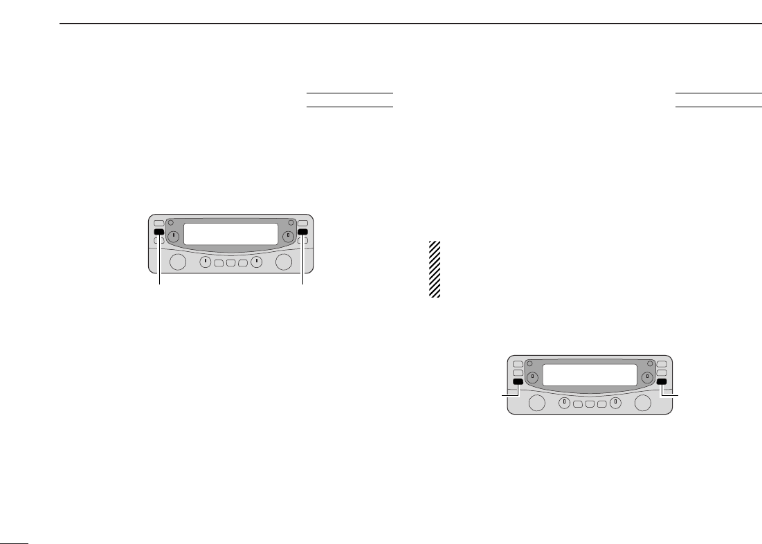
■ Partial reset
If you want to initialize the operating conditions (VFO fre-
quency, VFO settings, set mode contents) without clearing
the memory contents, a partial reset function is available.
➥ While pushing either band’s [VFO/MR•S.MW], turn the
power ON to partially reset the both bands at same time.
■ All reset
The function display may occasionally display erroneous in-
formation (e.g. when first applying power). This may be
caused externally by static electricity or by other factors.
If this problem occurs, turn power OFF. After waiting a few
seconds, turn power ON again. If the problem persists, per-
form the following procedure.
• Partial resetting is also available. See left for details.
IMPORTANT!:
Resetting the receiver CLEARS all memory information
and initializes all values in the receiver to their default set-
tings.
➥ While pushing both band’s [MHz•TS], turn the power ON
to reset the CPU.