v
TABLE OF CONTENTS
FOREWORD .............................................................. i
IMPORTANT ............................................................... i
EXPLICIT DEFINITIONS ............................................ i
SUPPLIED ACCESSORIES ...................................... ii
SPECIFICATIONS ..................................................... ii
OPTIONS ................................................................... ii
PRECAUTIONS ........................................................ iii
ABOUT APCO PROJECT 25 .................................... iv
TABLE OF CONTENTS ............................................. v
1 CONNECTION ................................................. 1–2
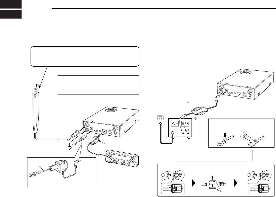
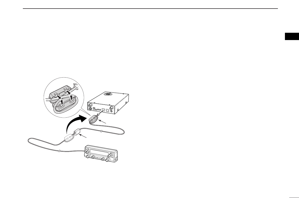
■ Rear panel connection....................................... 1
■ Antenna installation .......................................... 2
2PANEL DESCRIPTION .................................. 3–10
■ Front panel—controller ..................................... 3
■ Function display ................................................ 7
■ Rear panel—main unit ...................................... 9
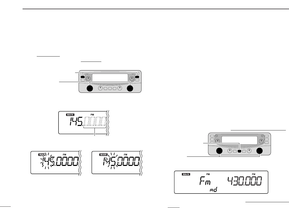
3 SETTING A FREQUENCY ........................... 11–13
■ Preparation ..................................................... 11
■ Tuning step selection ...................................... 12
■ Using the tuning dial ....................................... 13
■ Receive mode selection ................................. 13
4 BASIC OPERATION .................................... 14–22
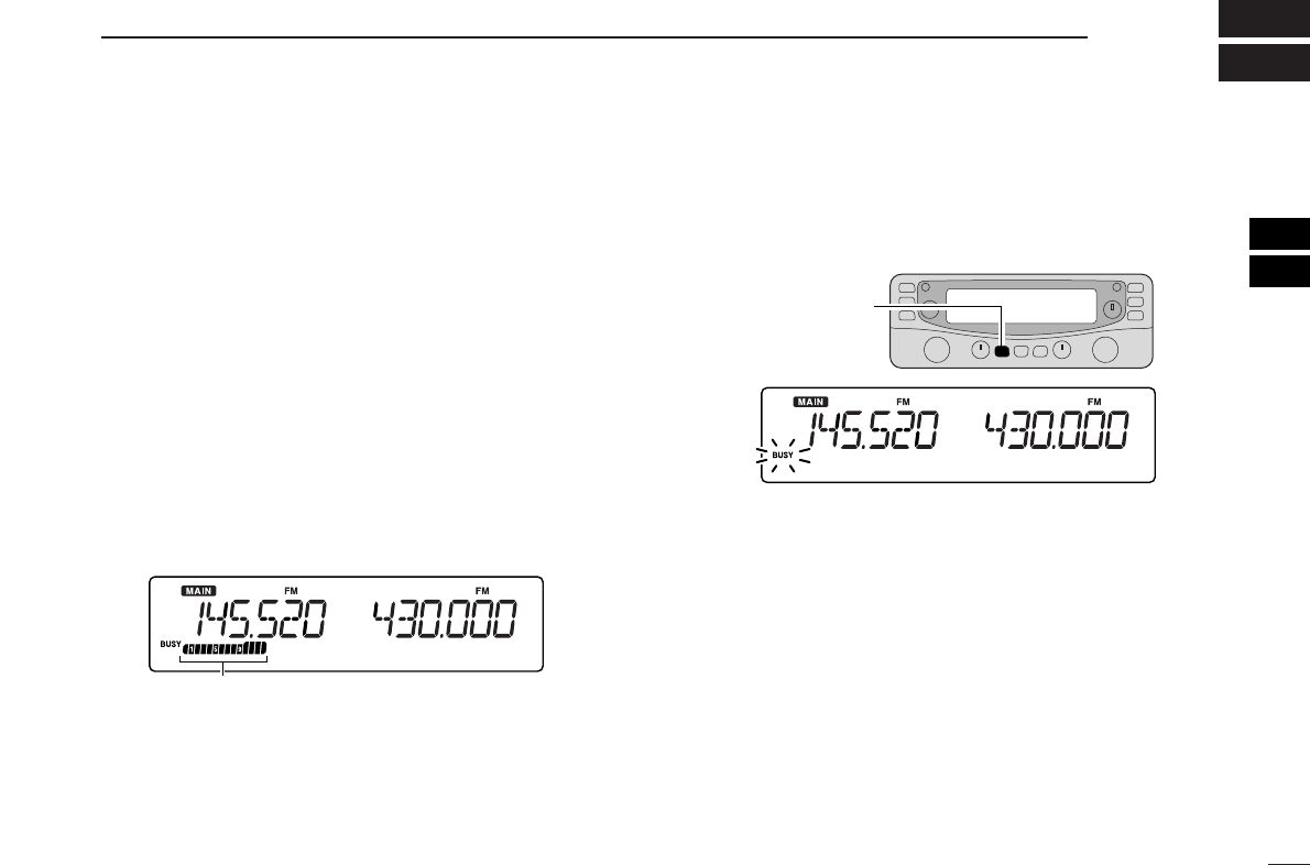
■ Receiving ........................................................ 14
■ Monitor function .............................................. 14
■ Lock function .................................................. 15
■ Attenuator function .......................................... 15
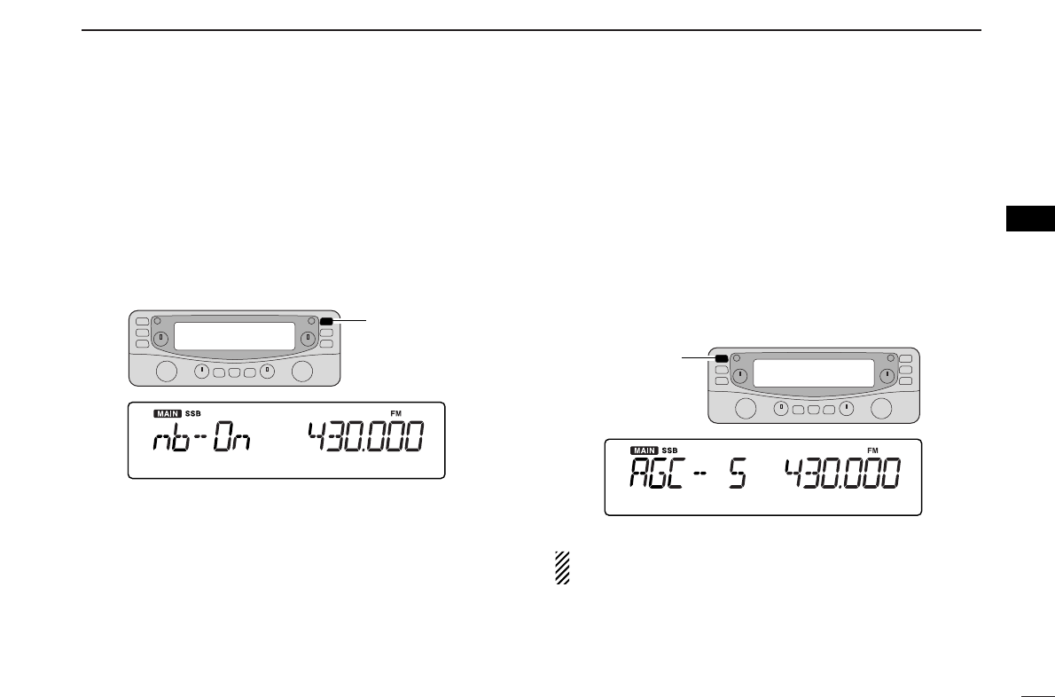
■ NB function ..................................................... 16
■ AGC function .................................................. 16
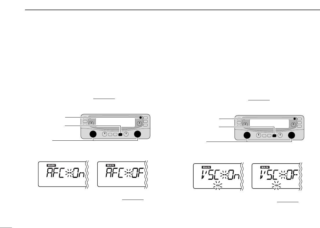
■ AFC function ................................................... 17
■ VSC function ................................................... 17
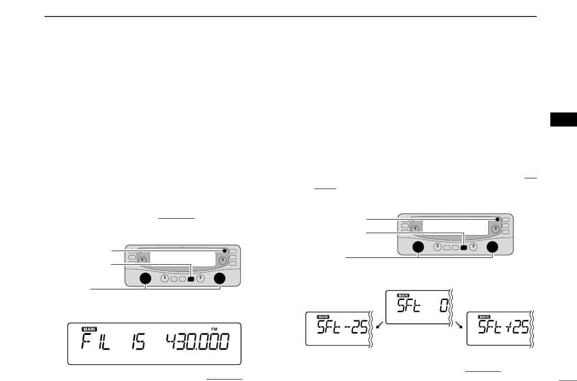
■ IF filter selection ............................................. 18
■ IF shift function ............................................... 18
■ Duplex operation ............................................ 19
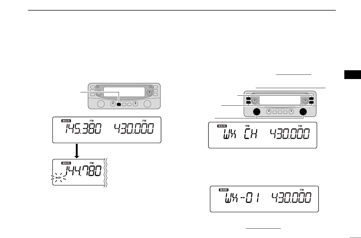
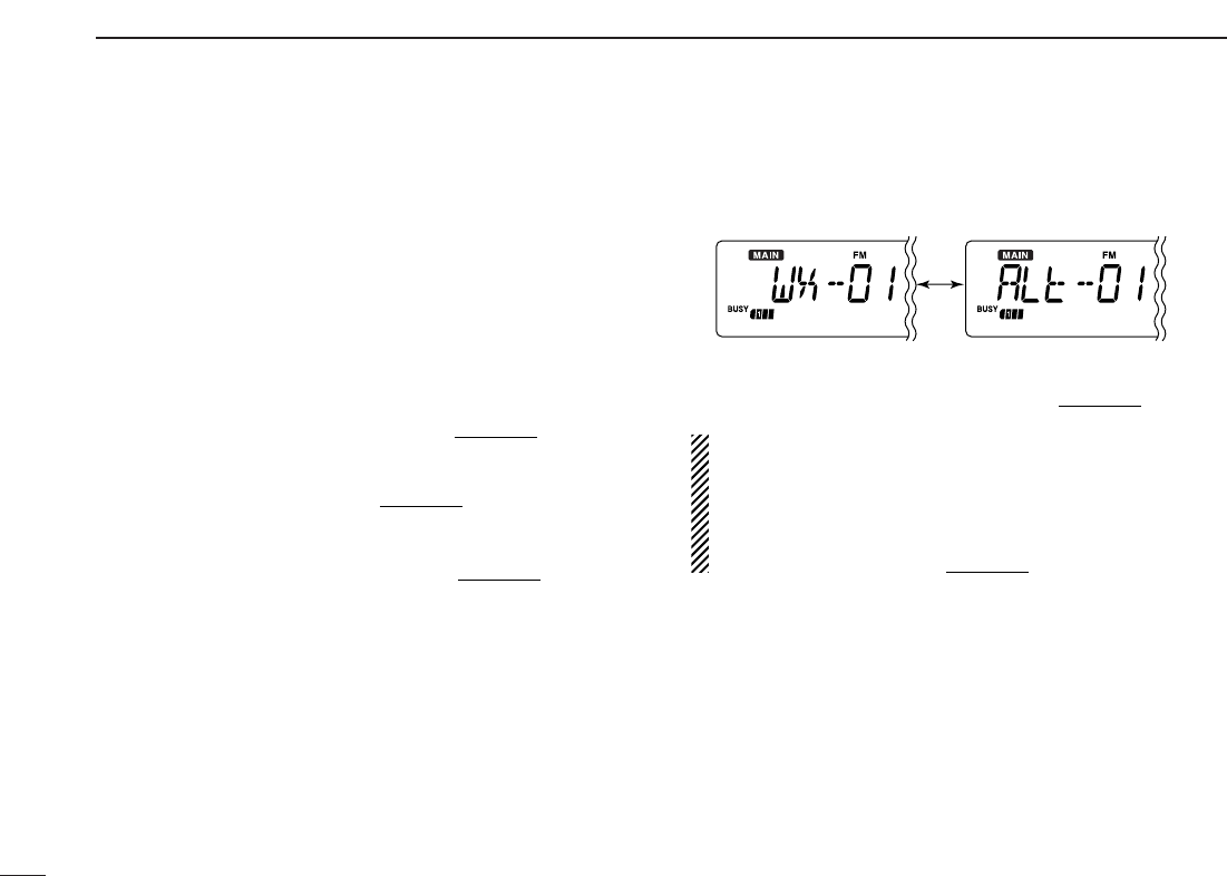
■ Weather channel operation
(USA/CANADA versions only).............................. 20
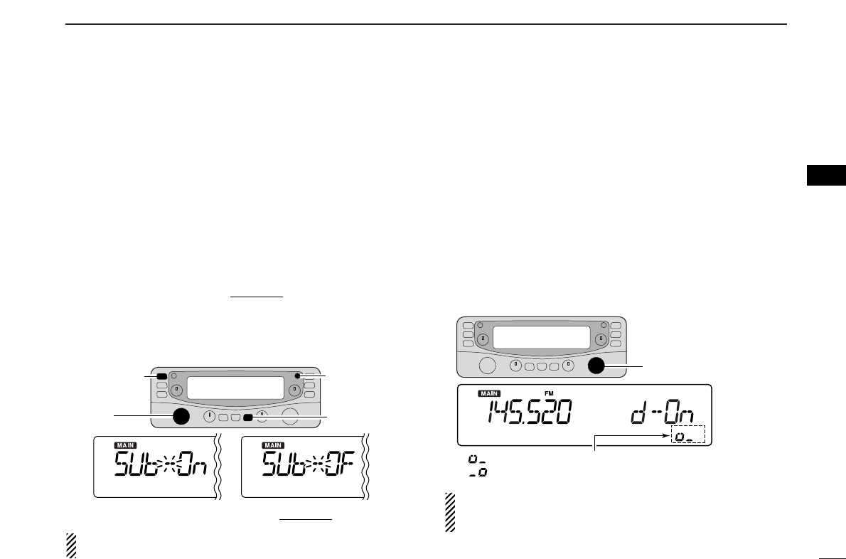
■ Single band operation ..................................... 22
5 MEMORY OPERATION ............................... 23–32
■ General description ........................................ 23
■ Memory channel selection .............................. 23
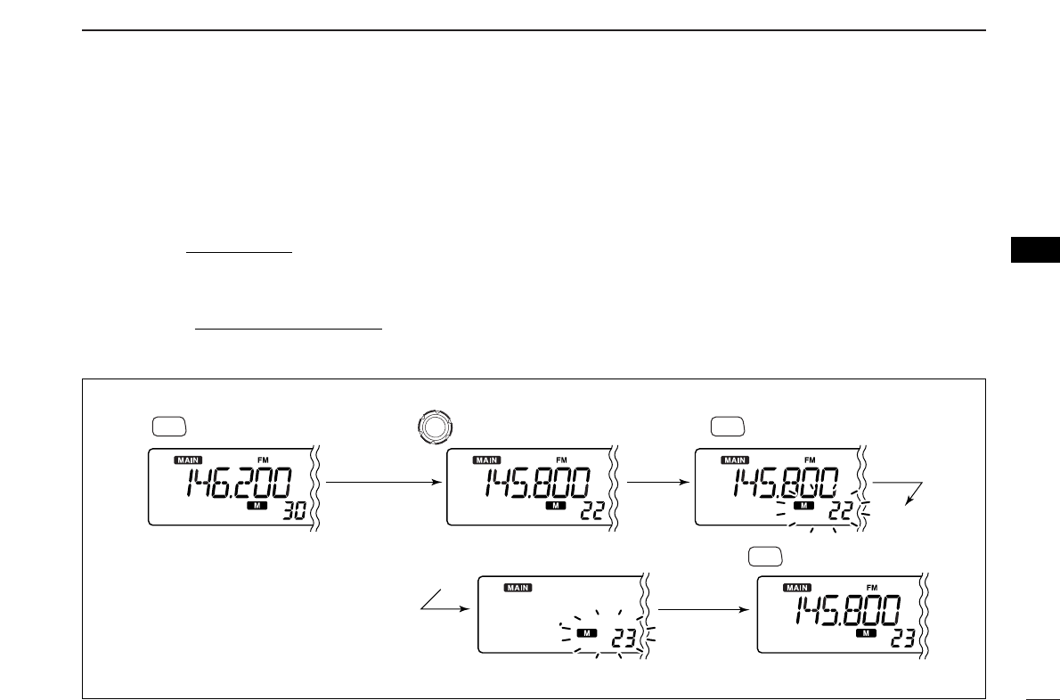
■ Programming a memory channel ................... 24
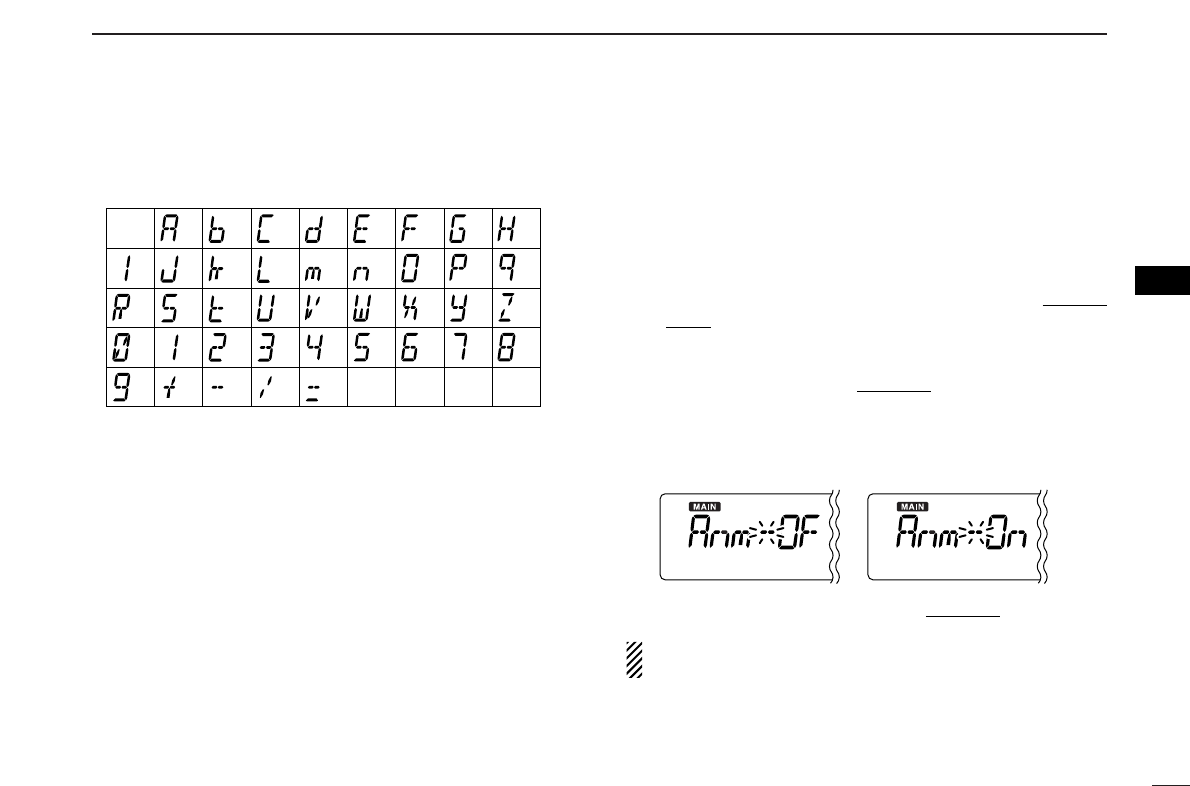
■ Programming channel names ........................ 25
■ Copying memory contents .............................. 27
■ Memory clearing ............................................. 29
■ Memory bank setting ...................................... 30
■ Memory bank selection ................................... 31
■ Transferring bank contents ............................. 31
6 SCAN OPERATION ..................................... 33–37
■ Scan types ...................................................... 33
■ Scan start/stop ................................................ 34
■ Scan edges programming .............................. 35
■ Skip scan ........................................................ 36
■ Scan resume condition ................................... 37