iv
TABLE OF CONTENTS
1
2
3
4
5
6
7
8
9
10
11
12
13
14
15
FOREWORD ................................................... i
IMPORTANT ................................................... i
EXPLICIT DEFINITIONS ................................ i
PRECAUTION ................................................ ii
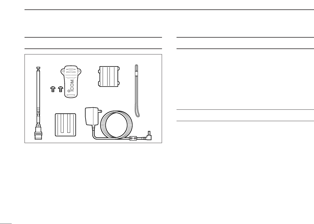
SUPPLIED ACCESSORIES .......................... iii
OPERATING THEORY .................................. iii
OPERATING NOTES .................................... iii
TABLE OF CONTENTS ................................ iv
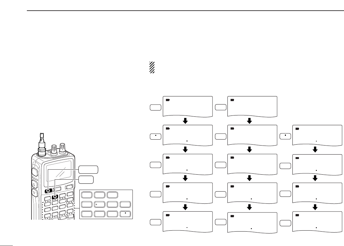
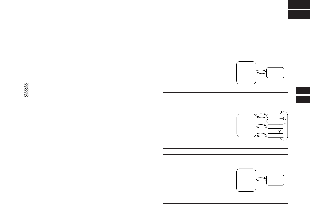
QUICK REFERENCE GUIDE ................. I–VIII
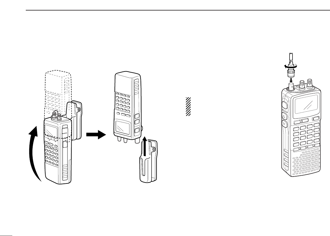
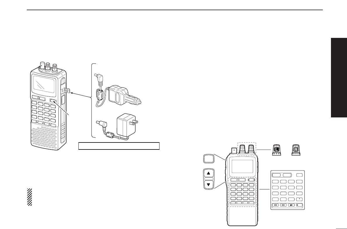
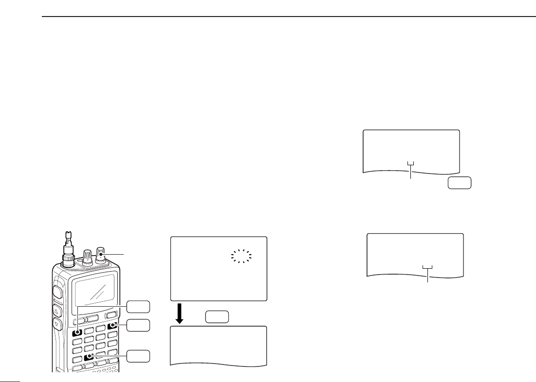
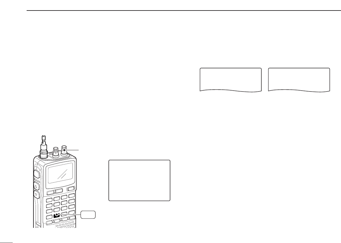
■ Preparations............................................ I
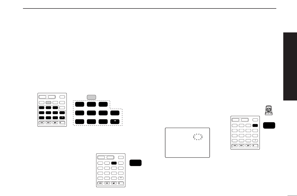
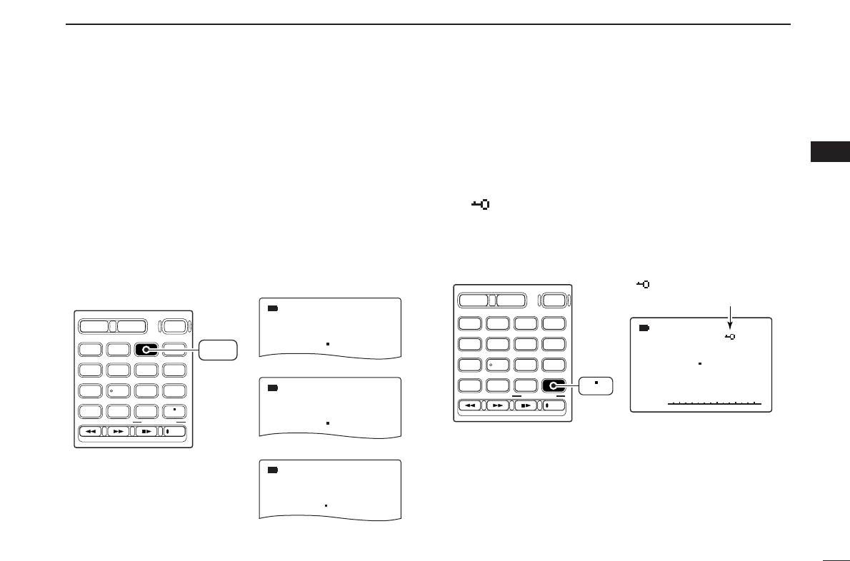
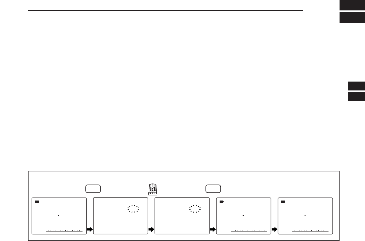
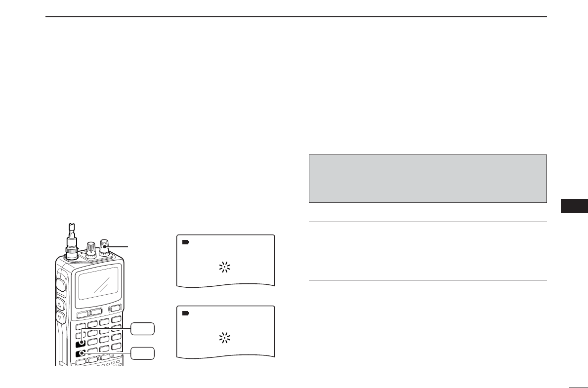
■ Your first scanning experience.............. IV
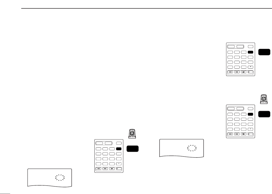
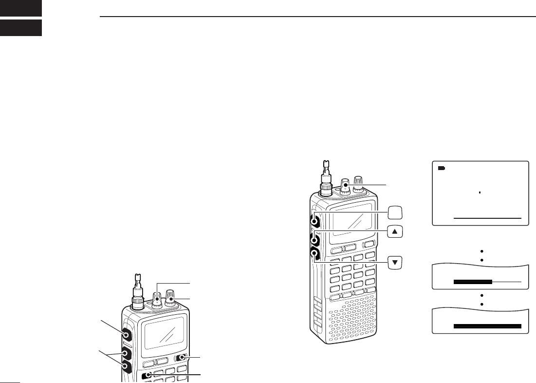
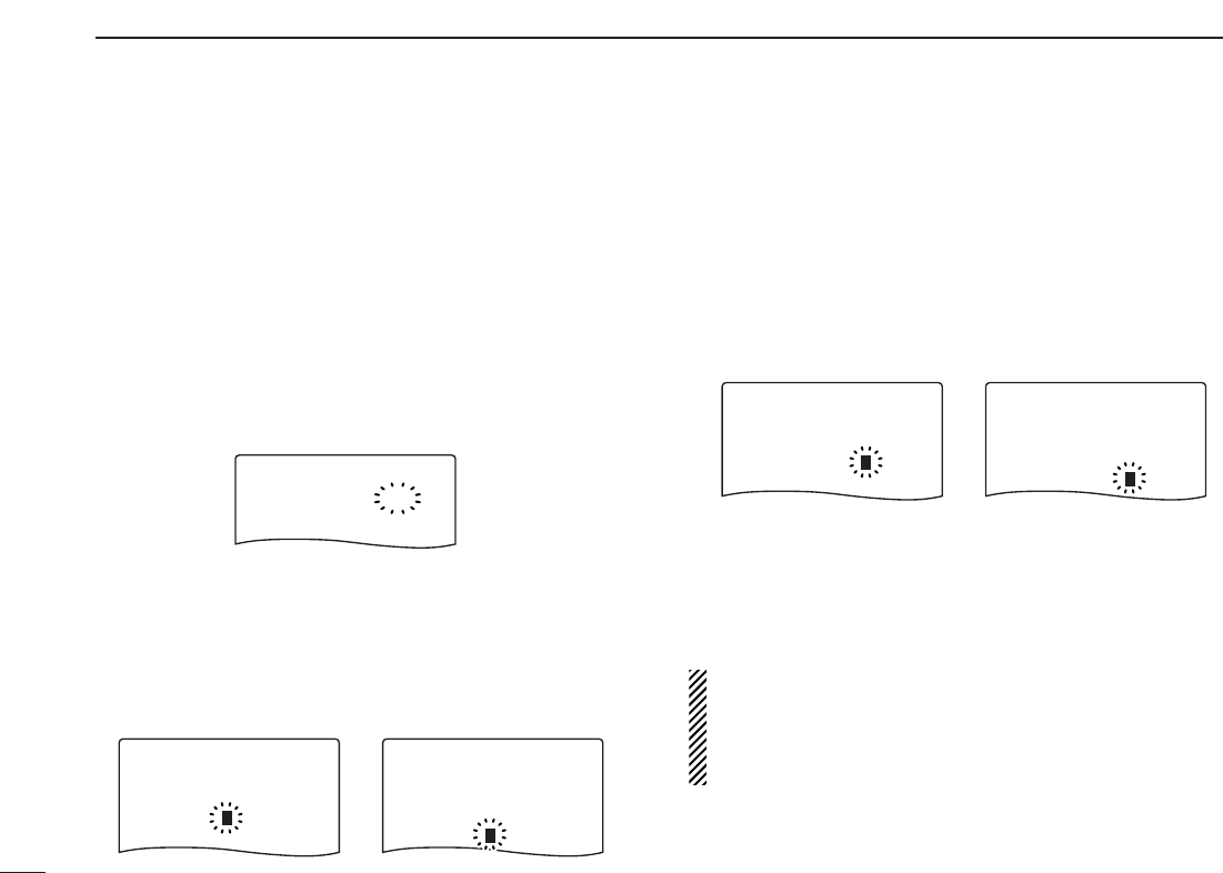
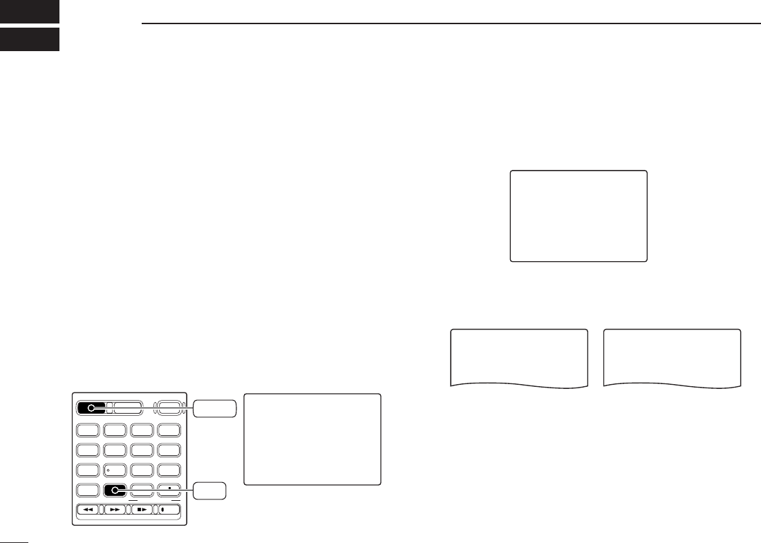
■ Memory programming........................... VI
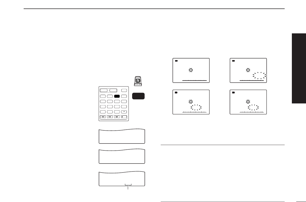
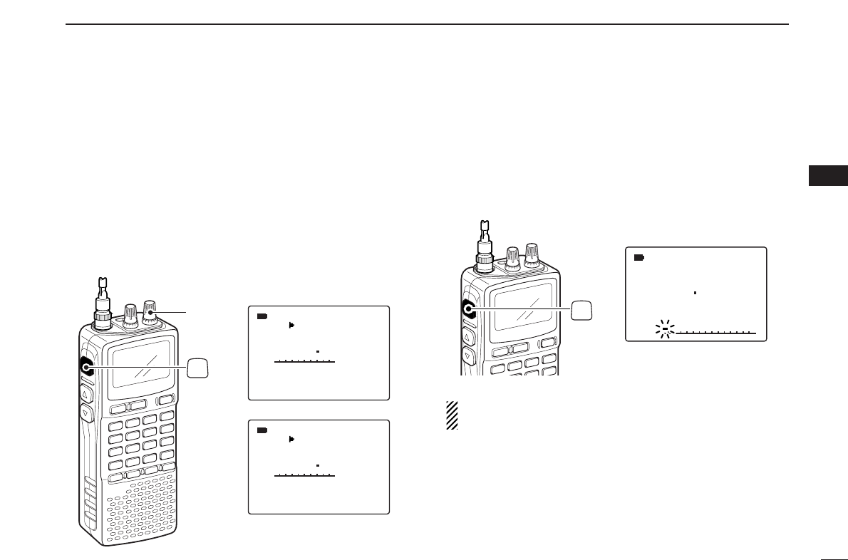
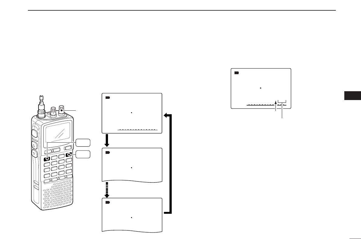
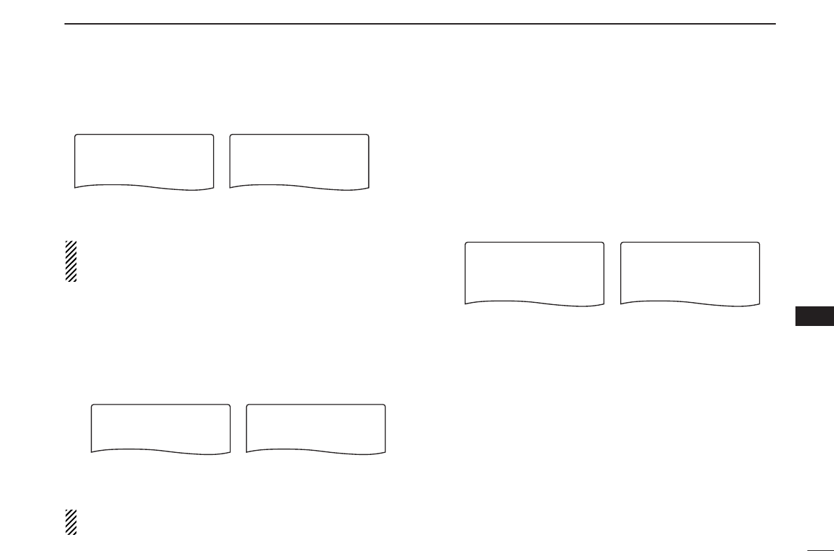
■ Programmed scan operation................ VII
1PANEL DESCRIPTION ......................... 1–7
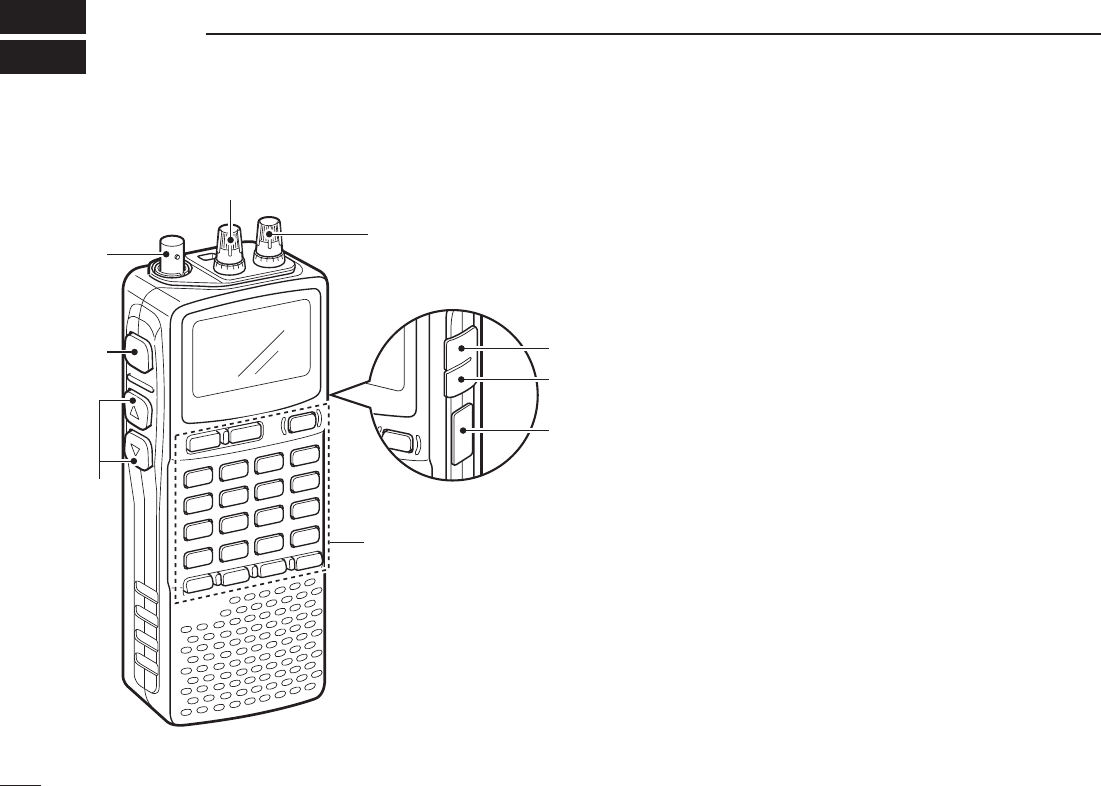
■ Front, top and side panels ..................... 1
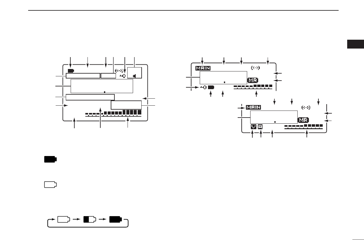
■ Function display ..................................... 6
2
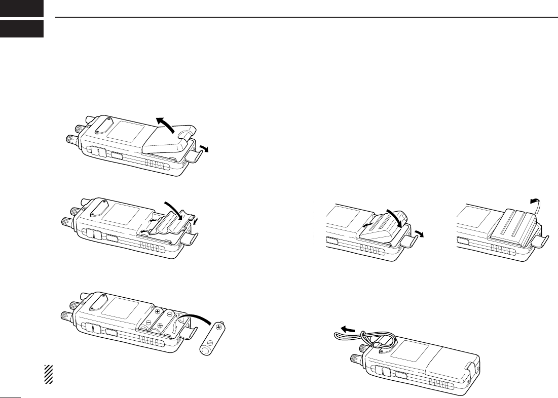
BATTERY INSTALLATION/CHARGING
... 8–10
■ Battery installation.................................. 8
■ Caution................................................... 9
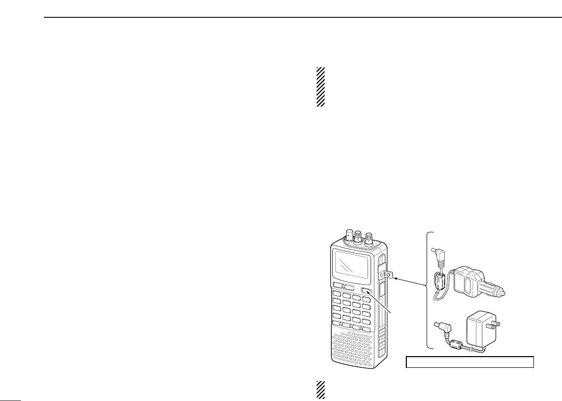
■ Battery charging ..................................... 9
3 FREQUENCY AND CHANNEL SETTING
.......................................................... 11–16
■ Mode selection...................................... 11
■ Operating band selection ..................... 12
■ Setting a tuning step............................. 14
■ Setting a frequency .............................. 14
■ Receive mode selection ....................... 16
■ Lock function ........................................ 16
4 BASIC OPERATION ......................... 17–23
■ Receiving.............................................. 17
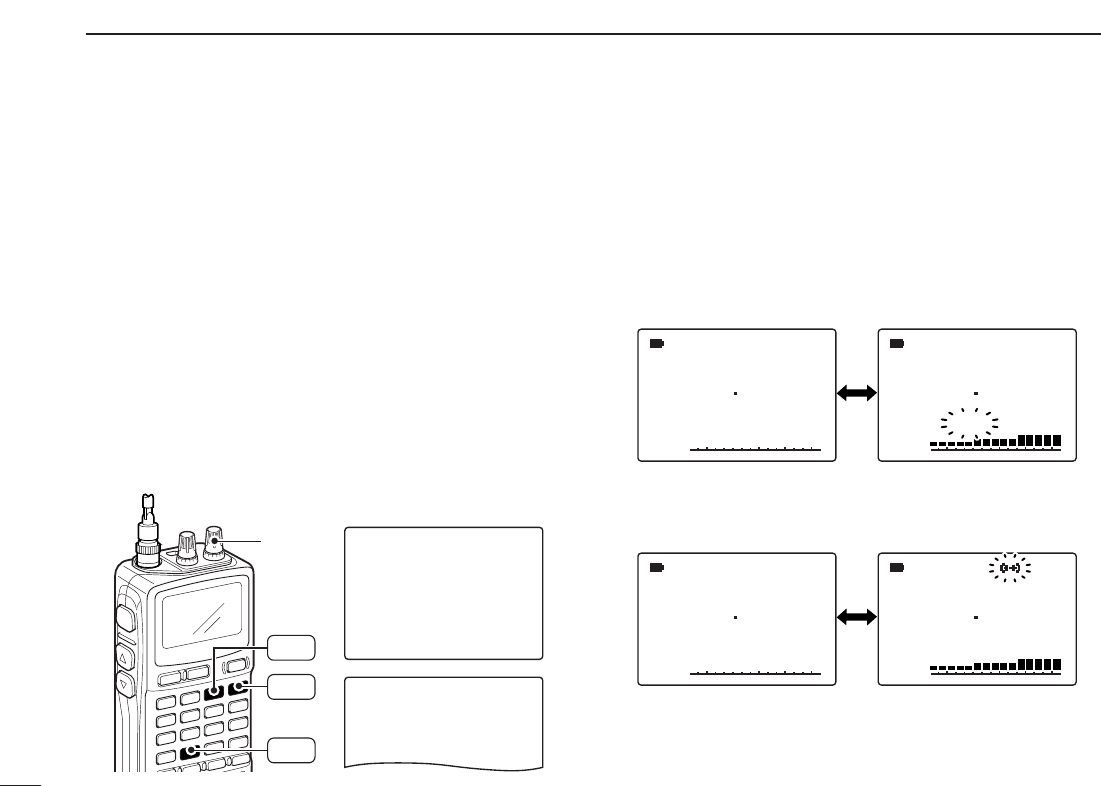
■ Setting audio volume............................ 17
■ Squelch level setting ............................ 18
■ Monitor function.................................... 18
■ Attenuator function ............................... 19
■ RF gain................................................. 19
■ Duplex operation .................................. 20
■ AFC function......................................... 21
■ NB/ANL functions ................................. 21
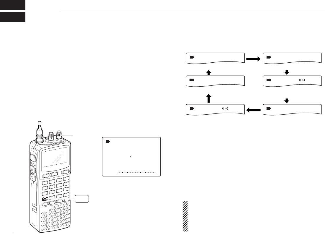
■ Band scope .......................................... 22
■ [DIAL] function assignment .................. 23
5 DUALWATCH OPERATION ............. 24–25
■ Main band selection ............................. 24
■ Band exchange .................................... 24
■ Setting audio volume............................ 25
■ Squelch level setting ............................ 25
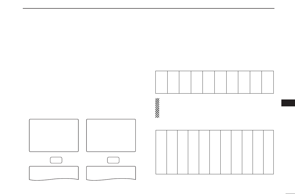
6 MEMORY CHANNELS ...................... 26–33
■ General description .............................. 26
■ Memory channel programming............. 26
■ Memory bank setting............................ 27
■ Memory bank selection ........................ 28
■ Programming memory/bank name....... 29
■
Selecting memory/bank name indication.....
30
■ Copying memory contents.................... 31
■ Memory clearing................................... 32
■ Erasing/transferring bank contents....... 33
7 SCAN OPERATION .......................... 34–41
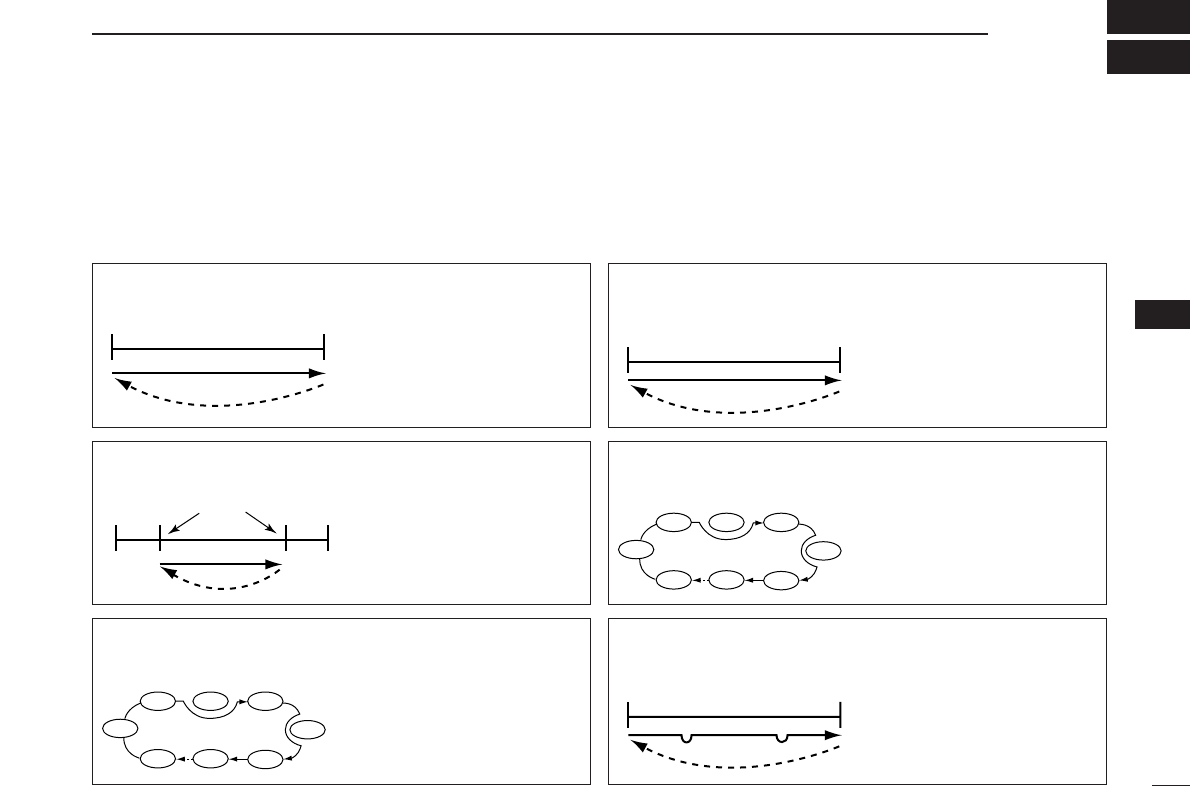
■ Scan types............................................ 34
■ Full/band/programmed scan................. 35
■ Scan edges programming .................... 36
■ Memory/bank/all bank scan.................. 37
■ Auto-memory write scan....................... 38
■ Skip channel/frequency setting ............ 39
■ Scan resume condition......................... 40
8 PRIORITY WATCH ........................... 42–44
■ Priority watch types .............................. 42
■ Priority watch operation........................ 43
9 COMFORTABLE RECEIVING........... 45–48
■ Tone/DTCS squelch operation ............. 45
■ Tone squelch frequency/DTCS code set-
ting........................................................ 46
■ DTCS polarity setting ........................... 47
■ Tone scan ............................................. 48
10 SET MODE ....................................... 49–59
■ General................................................. 49
■ Set mode items .................................... 50
11 OTHER FUNCTIONS ........................ 60–67
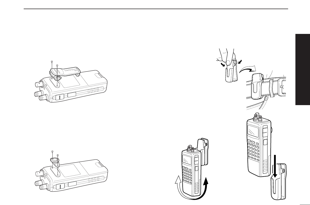
■ Antenna selection................................. 60
■ Weather channel operation .................. 61
■ Data cloning ......................................... 62
■ Auto power-off function......................... 63
■ IC recorder ........................................... 64
■ Partial reset .......................................... 67
■ All reset ................................................ 68
12 CONTROL COMMAND .................... 68–69
■ General................................................. 68
■ Data format........................................... 68
■ Command table.................................... 68
13 FREQUENCY TABLE ....................... 70–77
■ TV channels ......................................... 70
■ VHF marine channels........................... 73
■ Weather channels................................. 73
■ Other communications in the USA ....... 74
■
Other communications—other countries
.... 76
14 MAINTENANCE ...................................... 78
■ Troubleshooting.................................... 78
15 SPECIFICATIONS .................................. 79
16 OPTIONS ................................................ 80
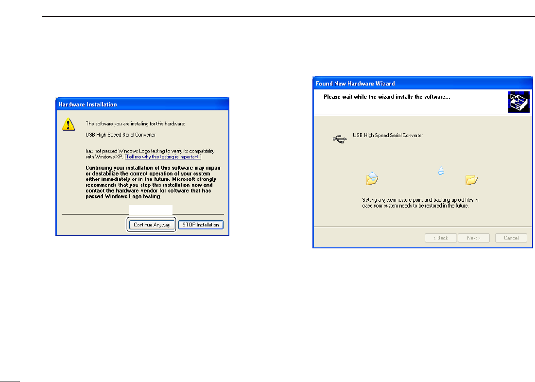
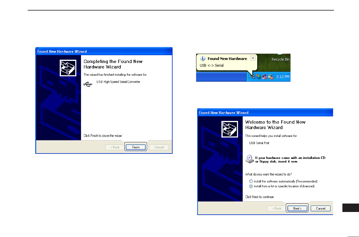
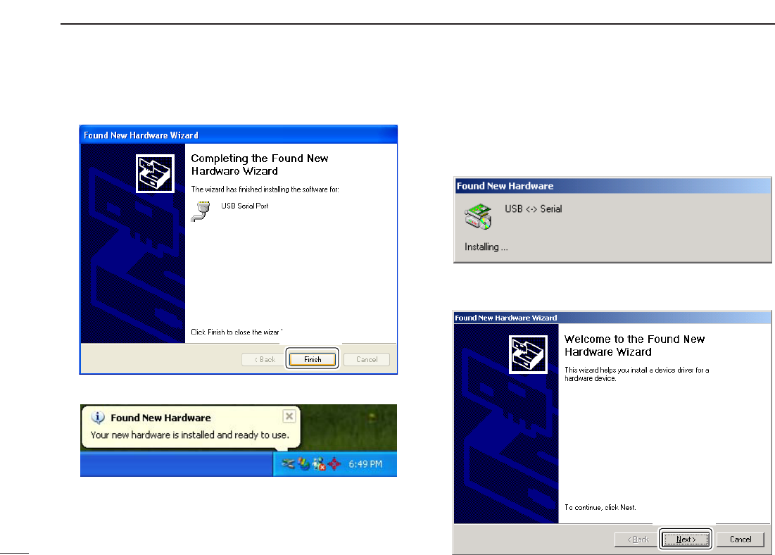
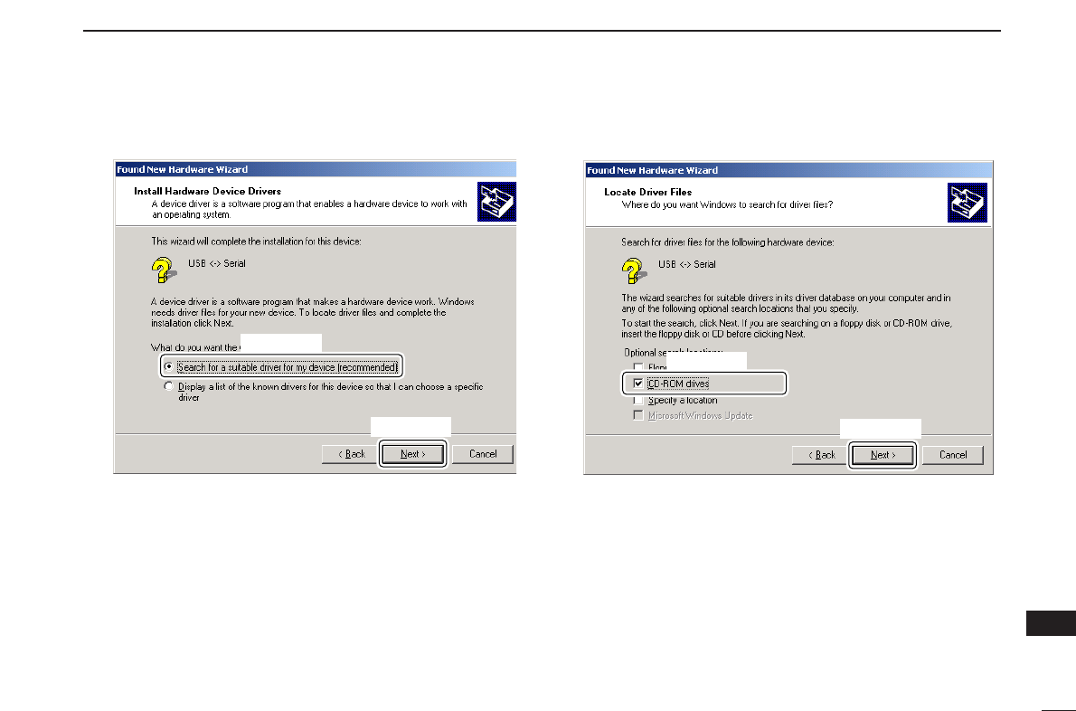
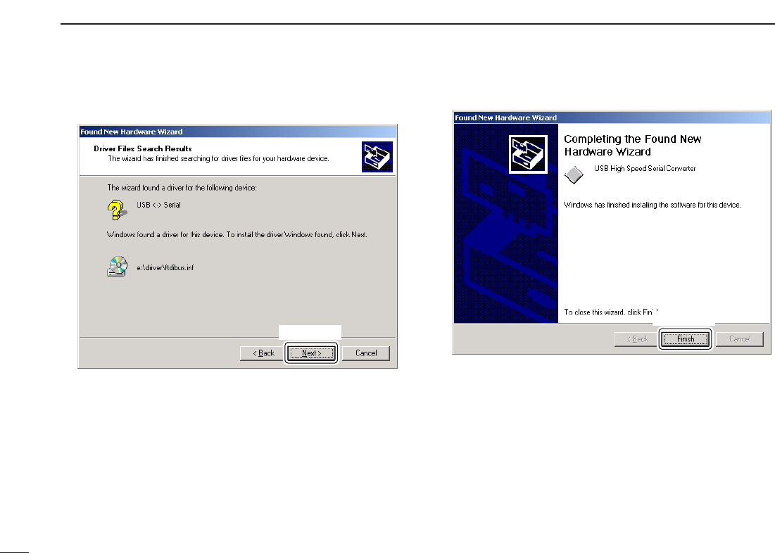
17 DRIVER INSTALLATION ........................ 81
18 POCKET GUIDE ..................................... 92
19 CE ........................................................... 94
16
17
18
19