FOREWORD ...................................... i
EXPLICIT DEFINITIONS ................... i
CAUTIONS ......................................... i
SUPPLIED ACCESSORIES .............. ii
TABLE OF CONTENTS .................... iii
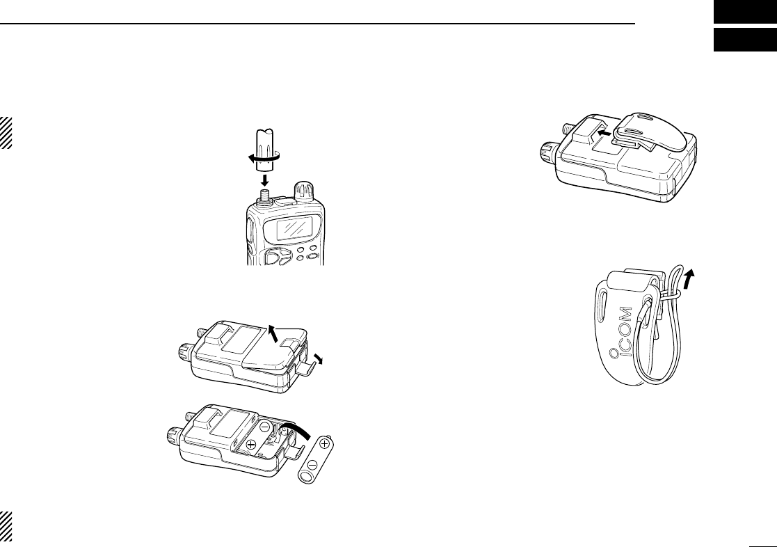
1 ACCESSORY ATTACHMENT ..... 1
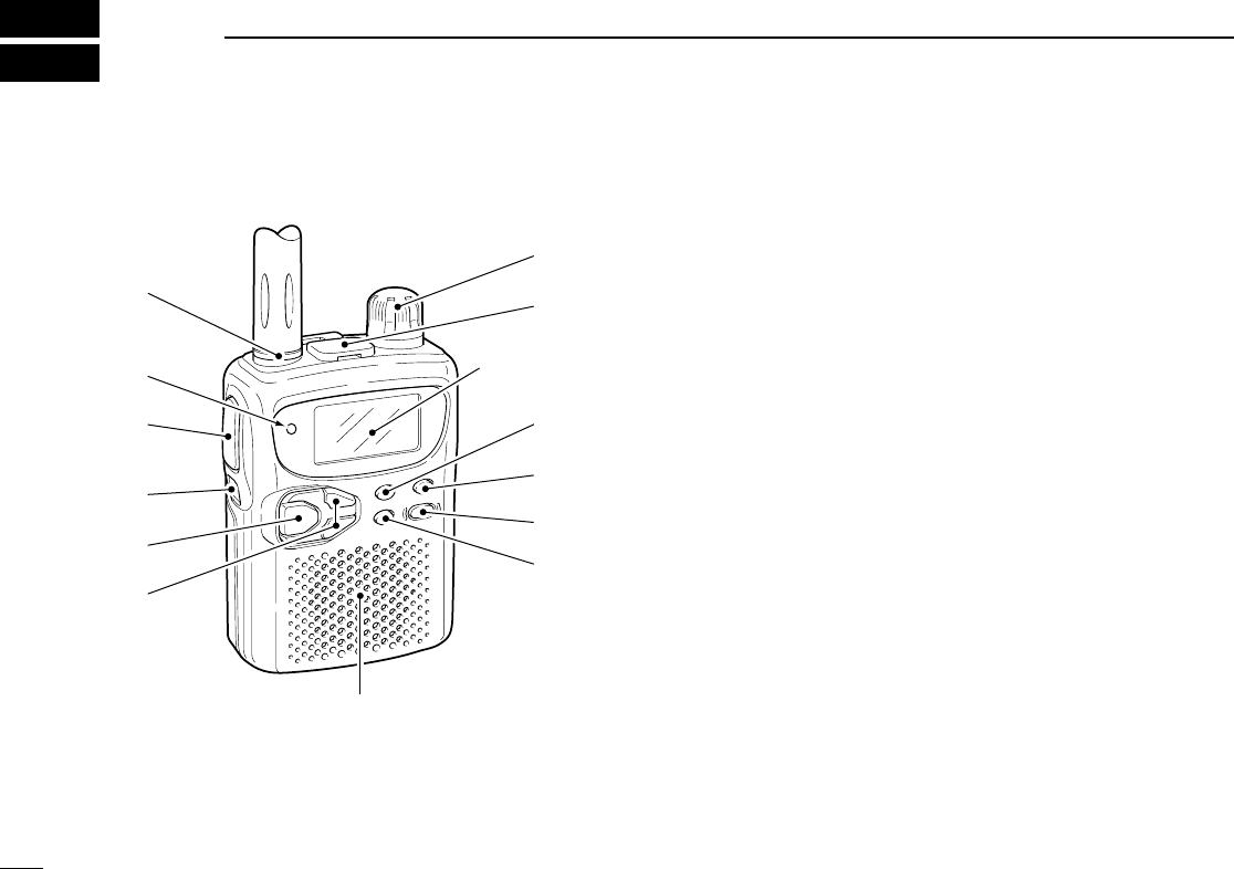
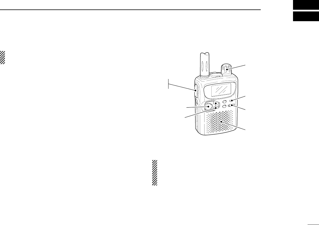
2 PANEL DESCRIPTION .......... 2–5
■Panel description ...................... 2
■Function display ........................ 4
3 FREQUENCY AND CHANNEL
SETTING ................................ 6–8
■
VFO and memory/call channels
.. 6
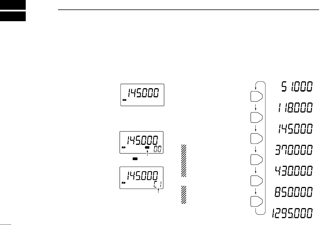
■Operating band selection .......... 6
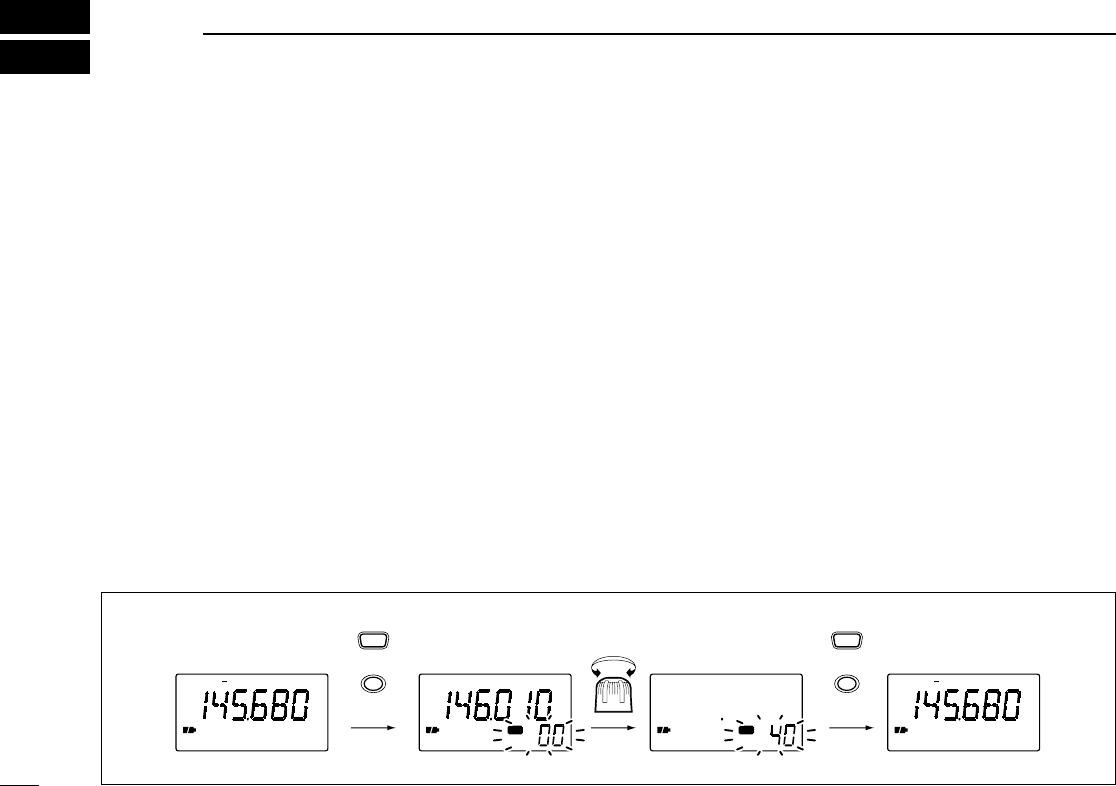
■Setting a frequency ................... 7
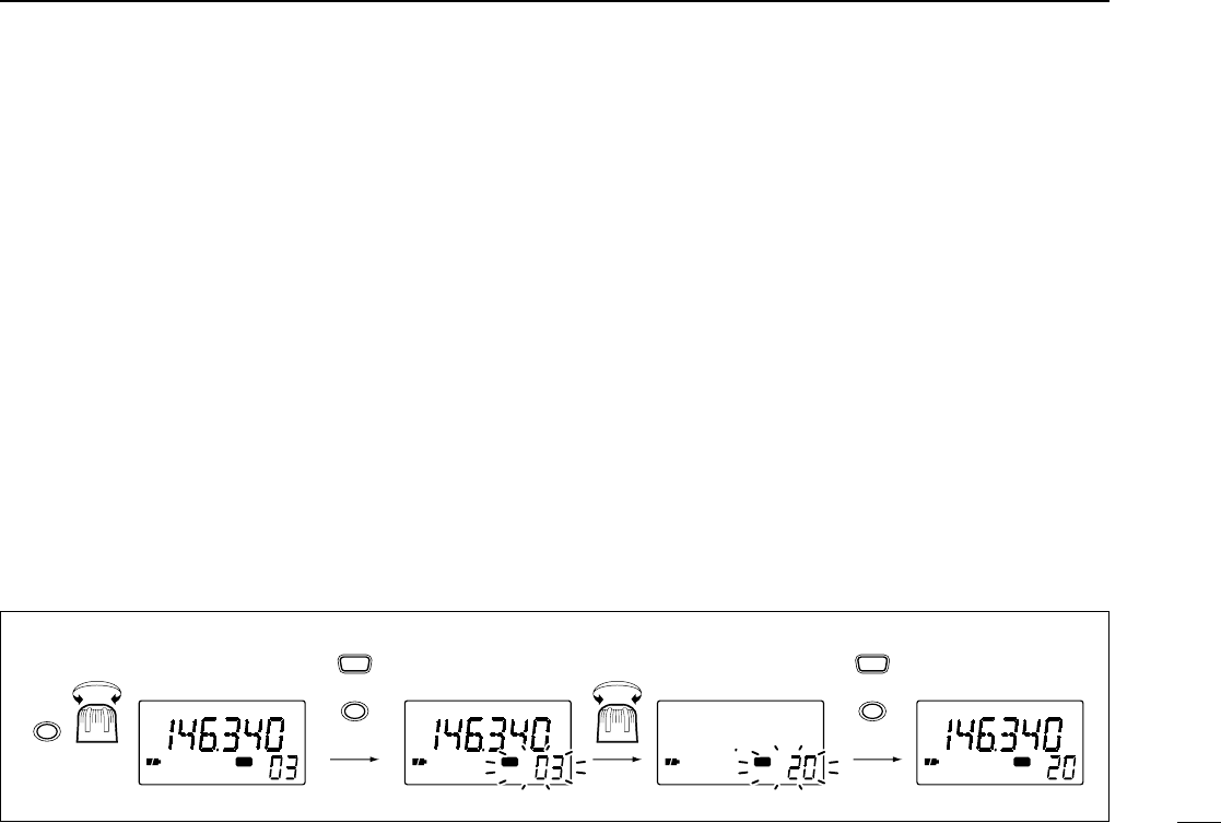
■Setting a tuning step ................. 7
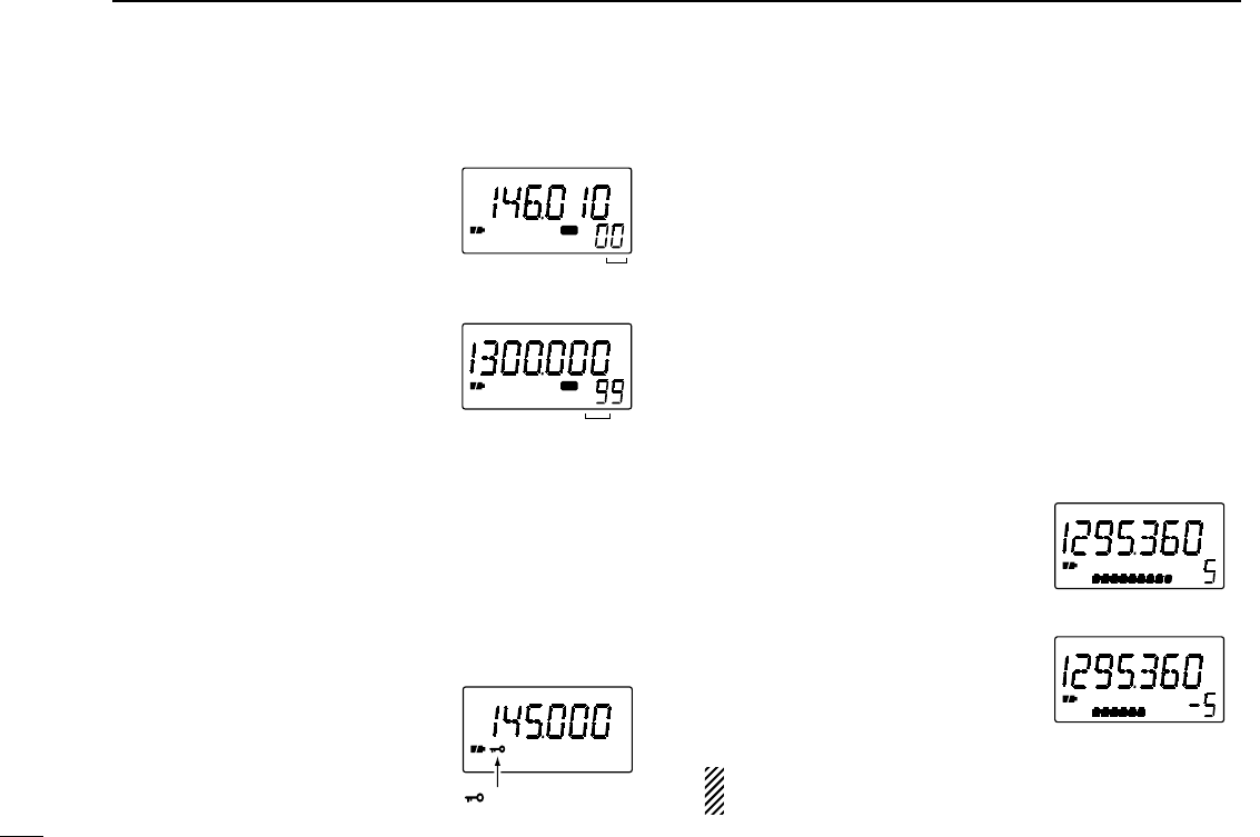
■Selecting a memory channel .... 8
■Lock function ............................ 8
■RIT function .............................. 8
4 BASIC OPERATION ............. 9–11
■Receiving and transmitting ....... 9
■Setting volume level ................ 10
■Setting squelch level ............... 10
■Monitor function ...................... 10
■Receive mode selection ......... 11
■Display backlighting ................ 11
5
MEMORY/CALL CHANNELS
.. 12–14
■General ................................... 12
■
Programming during selection
.. 12
■Programming after selection ... 13
■Transferring memory contents
to another memory ................. 13
■Memory clear .......................... 14
■Call channel ............................ 14
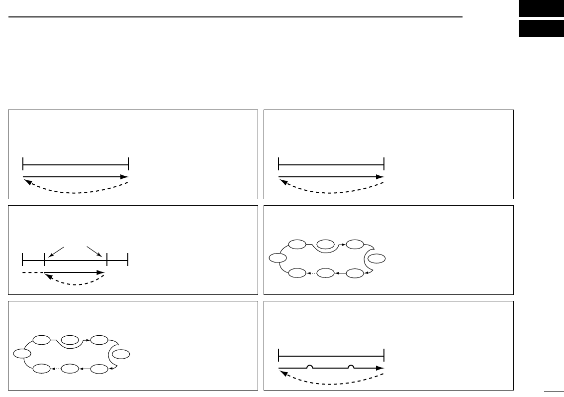
6 SCAN OPERATION ............ 15–19
■Scan types .............................. 15
■Full/band/programmed scan ... 16
■Memory (bank) scan ............... 16
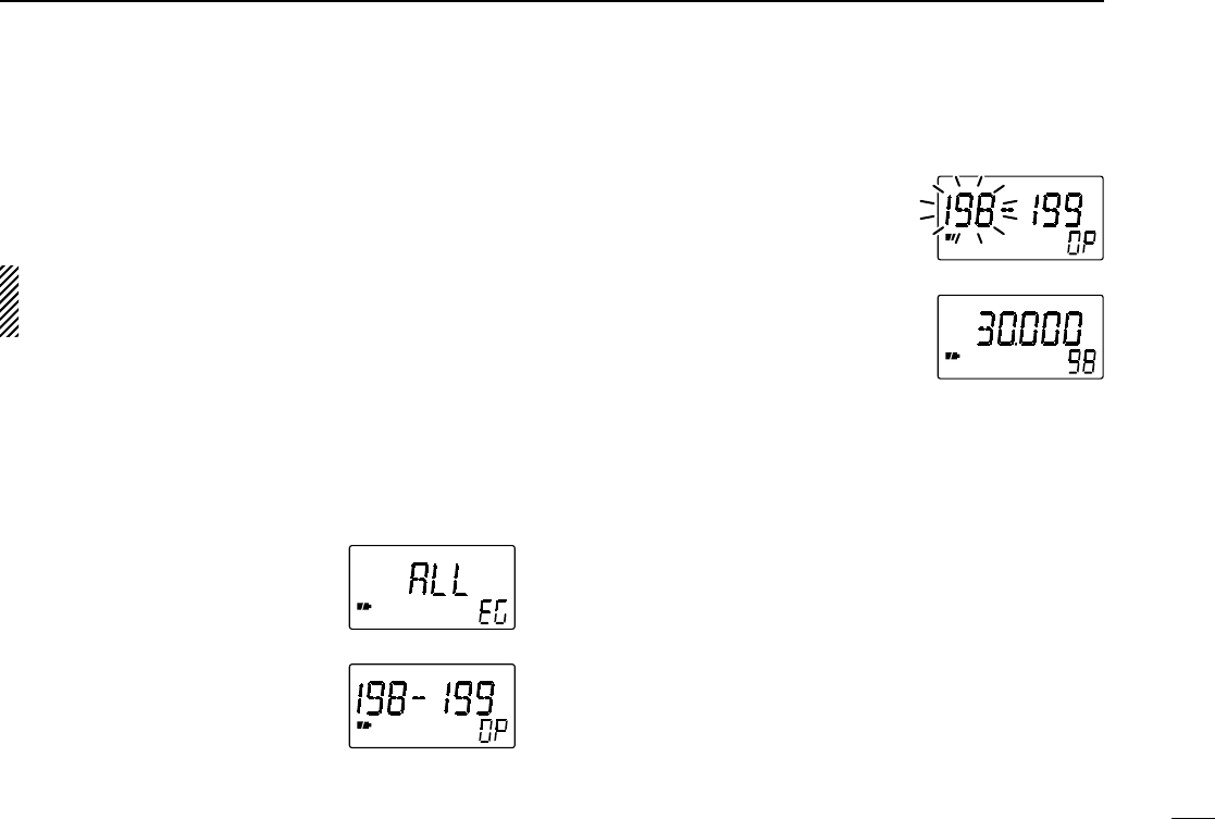
■Selecting scan edges ............. 17
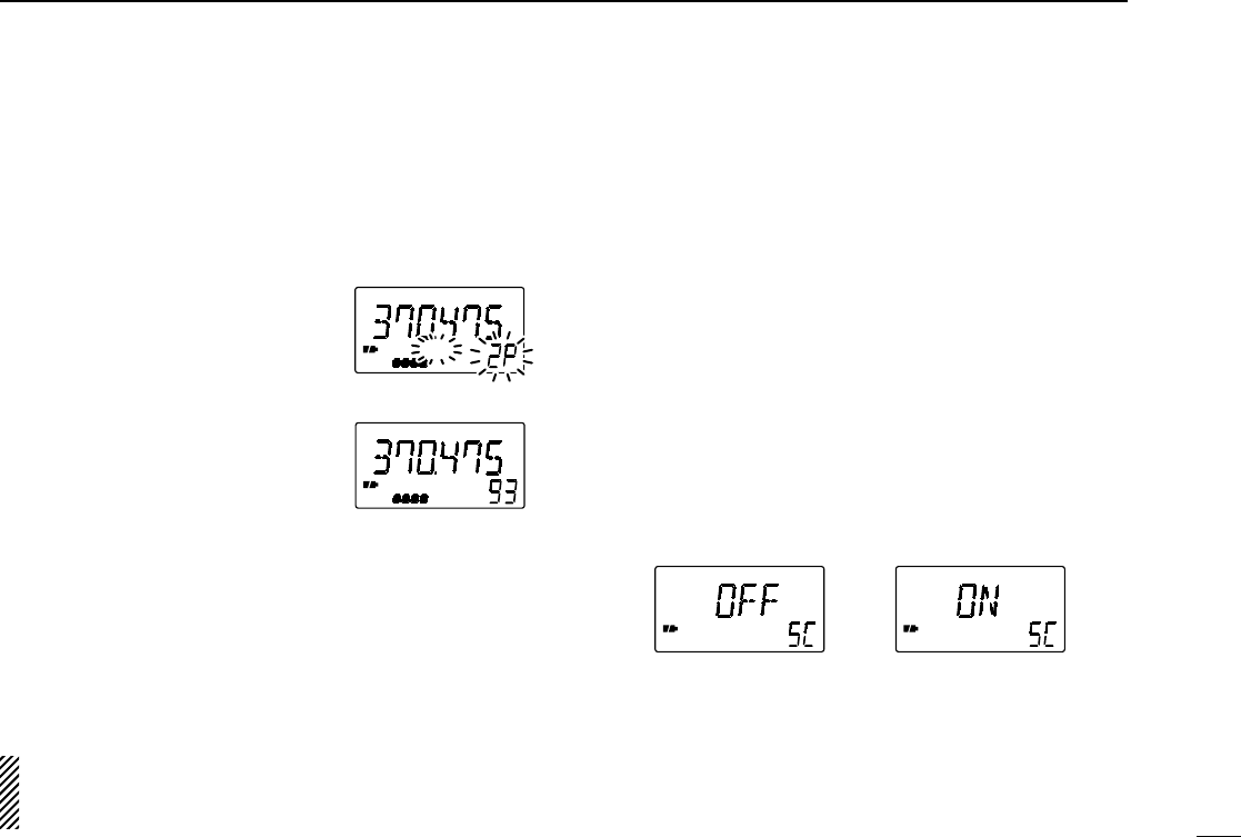
■Skip channel setting ............... 18
■Scan resume condition ........... 18
■Frequency skip function .......... 19
7 PRIORITY WATCH ............. 20–21
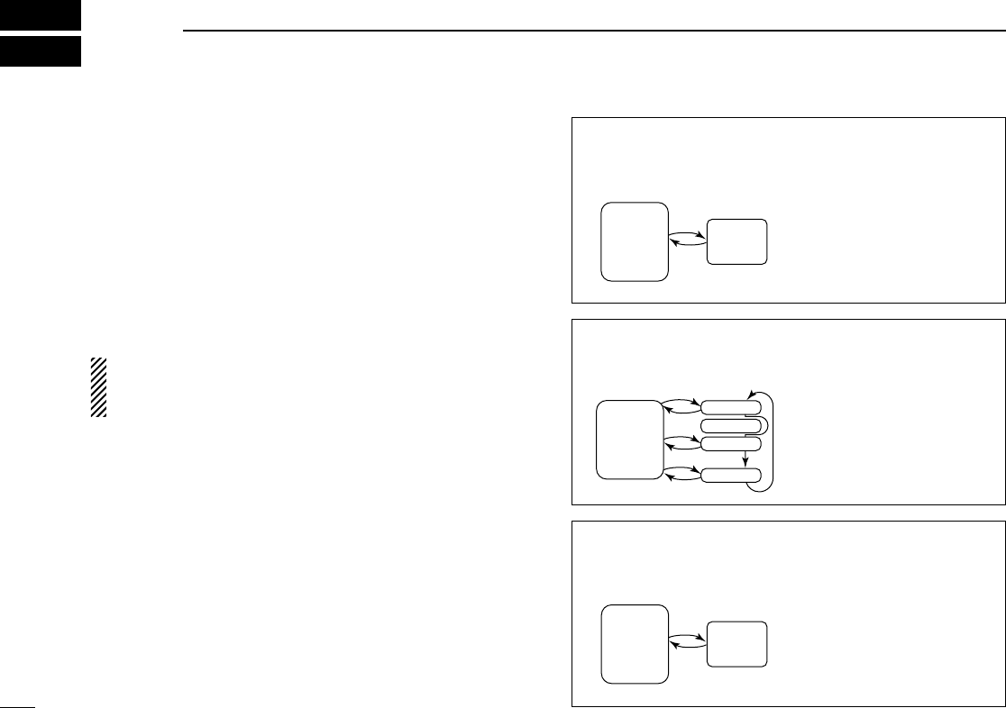
■Priority watch types ................ 20
■Priority watch operation .......... 21
8 REPEATER OPERATION .. 22–25
■General ................................... 22
■Subaudible (repeater) tones ... 23
■1750 Hz tone .......................... 24
■Offset frequency ..................... 24
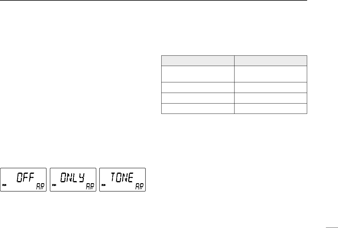
■Auto repeater function ............ 25
9 SUBAUDIBLE TONE
OPERATION ....................... 26–27
■Tone squelch operation .......... 26
■Pocket beep operation ............ 27
■Tone scan ............................... 27
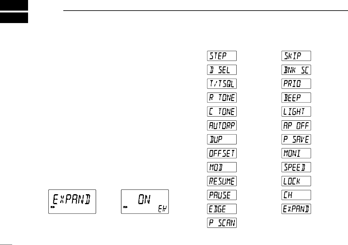
10 OTHER FUNCTIONS ......... 28–32
■Set mode ................................ 28
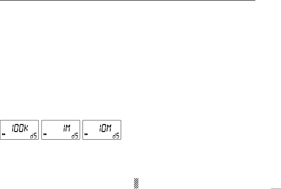
■Dial select step ....................... 29
■Beep tones ............................. 29
■Power saver ............................ 29
■Auto power-off function ........... 30
■Monitor switch function ........... 30
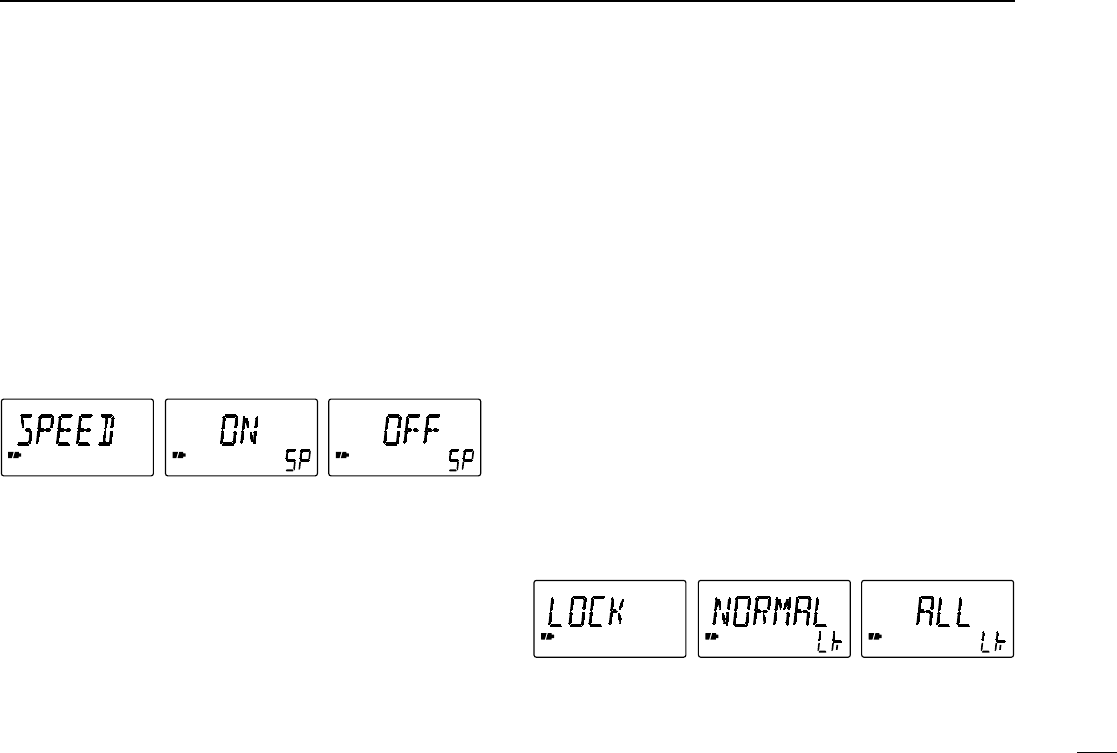
■Dial speed acceleration .......... 31
■Lock function effect ................. 31
■Channel indication mode ........ 32
■Partial reset ............................ 32
■All reset ................................... 32
11 TROUBLESHOOTING .............. 33
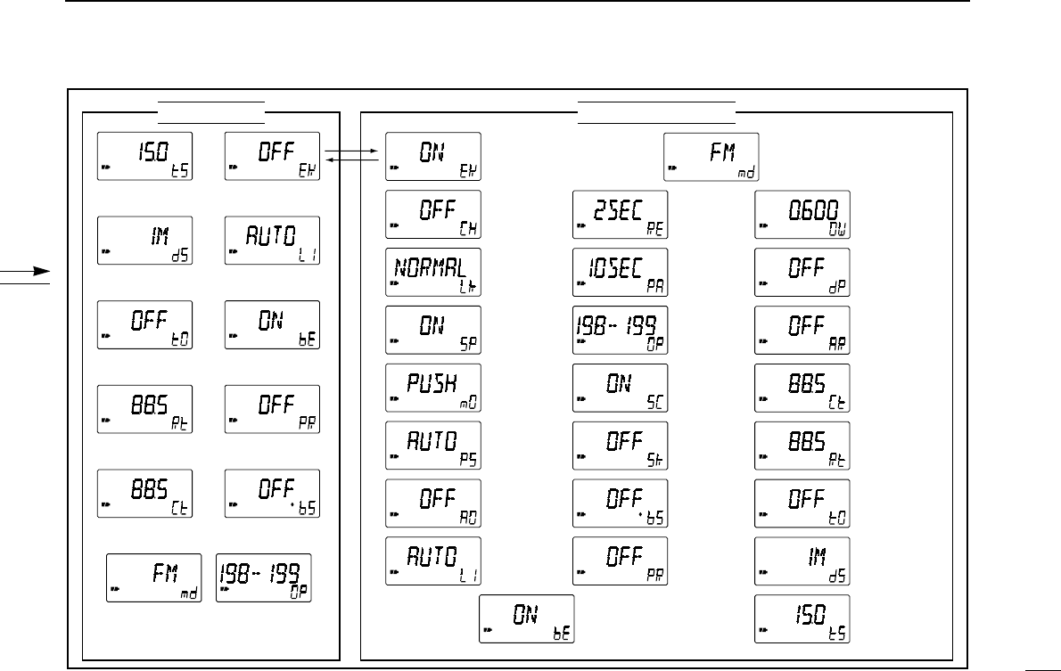
12
OPERATION FLOW CHART
... 34–35
13 SPECIFICATIONS .............. 36–37
14 OPTIONS ................................... 38
iii
TABLE OF CONTENTS