12634
67
Verklein
Vergroot
Pagina terug
1/80
Pagina verder
INSTRUCTION MANUAL
iM505
VHF MARINE TRANSCEIVER
i
FOREWORD
Thank you for purchasing this Icom product. The IC-M505
VHF MARINE TRANSCEIVER
is designed and built with Icom’s
state of the art technology and craftsmanship. With proper
care, this product should provide you with years of trouble-
free operation.
We want to take a couple of moments of your time to thank
you for making the IC-M505 your radio of choice, and hope
you agree with Icom’s philosophy of “technology first.” Many
hours of research and development went into the design of
your IC-M505.
D
FEATURES
Simple operation with large keys
Easy to hear speaker
Built-in DSC meets ITU Class D requirement
Rugged waterproof construction
Optional COMMANDMIC III™ (HM-162E) is
available
IMPORTANT
READ ALL INSTRUCTIONS carefully and completely
before using the transceiver.
SAVE THIS INSTRUCTION MANUAL — This in-
struction manual contains important operating instructions for
the IC-M505.
EXPLICIT DEFINITIONS
WORD DEFINITION
R WARNING!
CAUTION
NOTE
Personal injury, fire hazard or electric shock
may occur.
Equipment damage may occur.
Recommended for optimum use. No risk of
personal injury, fire or electric shock.
CLEAN THE TRANSCEIVER AND MICROPHONE THOR-
OUGHLY WITH FRESH WATER after exposure to water
including salt, otherwise, the keys and switch may become
inoperable due to salt crystallization.
Icom, Icom Inc. and the logo are registered trademarks of Icom Incor-
porated (Japan) in the United States, the United Kingdom, Germany, France,
Spain, Russia and/or other countries.
COMMANDMIC III is a trademark of Icom Incorporated (Japan) in the United
States.
ii
IN CASE OF EMERGENCY
If your vessel requires assistance, contact other vessels and
the Coast Guard by sending a Distress call on Channel 16.
Or, transmit your Distress call using digital selective calling
on Channel 70.
INSTALLATION NOTE
The installation of this equipment should be made in such a
manner as to respect the EC recommended electromagnetic
field exposure limits (1999/519/EC).
The maximum RF power available from this device is 25
watts. The antenna should be installed as high as possible
for maximum efficiency and that this installation height should
be at least 5 meters above ground (or accessible) level. In the
case where an antenna cannot be installed at a reasonable
height, then the transmitter should neither be continuously
operated for long periods if any person is within 5 meters of
the antenna, nor operated at all if any person is touching the
antenna.
In all cases any possible risk depends on the transmitter
being activated for long periods. (actual recommendation lim-
its are specified as an average of 6 minutes) Normally the
transmitter is not active for long periods of time. Some radio li-
censes will require that a timer circuit automatically cuts the
transmitter after 1–2 minutes etc.
Similarly some types of transmitter, SSB, CW, AM, etc. have a
lower ‘average’ output power and the perceived risk is even
lower.
USING DIGITAL SELECTIVE CALLING (Ch 70)
DISTRESS CALL PROCEDURE
1. While lifting up the key cover, push and hold
[DISTRESS] for 5 sec. until you hear 5 short beeps
change to one long beep.
2. Wait for an acknowledgment on Channel 70 from a coast
station.
After the acknowledgement is received, Channel 16 is auto-
matically selected.
3. Push and hold [PTT], then transmit the appropriate
information as listed above.
USING CHANNEL 16
DISTRESS CALL PROCEDURE
1. “MAYDAY MAYDAY MAYDAY.”
2. “THIS IS ...............” (name of vessel).
3. Say your call sign or other indication of the vessel (AND
9-digit DSC ID if you have one).
4. “LOCATED AT ...............” (your position).
5. State the nature of the distress and assistance required.
6. Give any other information which might facilitate the
rescue.
iii
DOC
CE versions of the IC-M505 which display the
“CE” symbol on the serial number seal, comply
with the essential requirements of the Euro-
pean Radio and Telecommunication Terminal
Directive 1999/5/EC.
This warning symbol indicates that this equip-
ment operates in non-harmonised frequency
bands and/or may be subject to licensing condi-
tions in the country of use. Be sure to check that
you have the correct version of this radio or the
correct programming of this radio, to comply with
national licensing requirement.
DECLARATION
OF CONFORMITY
We Icom Inc. Japan
1-1-32, Kamiminami, Hirano-ku
Osaka 547-0003, Japan
Kind of equipment:
VHF MARINE TRANSCEIVER
This compliances is based on conformity with the following harmonised
standards, specifications or documents:
i)
EN 301 025-2 V1.2.1 (2004-09)
ii)
EN 301 025-3 V1.2.1 (2004-09)
iii) EN 60945 2002
iv) EN 60950-1 2001
v) EN 300 698-2 V1.1.1 ( 2000-08)
vi) EN 300 698-3 V1.1.1 ( 2001-05)
Type-designation: iM505
Signature
Declare on our sole responsibility that this equipment complies with the
essential requirements of the Radio and Telecommunications Terminal
Equipment Directive, 1999/5/EC, and that any applicable Essential Test
Suite measurements have been performed.
Version (where applicable):
0560
Authorized representative name
Place and date of issue
iv
FOREWORD …………………………………………………………… i
IMPORTANT …………………………………………………………… i
EXPLICIT DEFINITIONS ……………………………………………… i
IN CASE OF EMERGENCY…………………………………………… ii
INSTALLATION NOTE ………………………………………………… ii
DOC …………………………………………………………………… iii
TABLE OF CONTENTS ……………………………………………… iv
PRECAUTIONS ………………………………………………………… v
1 OPERATING RULES ……………………………………………… 1
2 PANEL DESCRIPTION ………………………………………… 2–5
Front panel ……………………………………………………… 2
Function display ………………………………………………… 4
Microphone ……………………………………………………… 5
3 BASIC OPERATION…………………………………………… 6–11
Channel selection ……………………………………………… 6
Receiving and transmitting……………………………………… 8
Call channel programming ……………………………………… 9
Channel comments …………………………………………… 10
Microphone Lock function …………………………………… 10
Display backlight ……………………………………………… 10
Optional voice scrambler operation ………………………… 11
4 SCAN OPERATION ………………………………………… 12–13
Scan types ……………………………………………………… 12
Setting TAG channels ………………………………………… 13
Starting a scan ………………………………………………… 13
5 DUALWATCH/TRI-WATCH ……………………………………… 14
Description ……………………………………………………… 14
Operation ……………………………………………………… 14
6 DSC OPERATION …………………………………………… 15–49
MMSI code programming……………………………………… 15
MMSI code check ……………………………………………… 16
DSC address ID………………………………………………… 17
Position and time programming ……………………………… 21
Position and time indication …………………………………… 22
GPS information indication …………………………………… 22
Distress call …………………………………………………… 23
Transmitting DSC calls ………………………………………… 26
Receiving DSC calls …………………………………………… 41
Received messages …………………………………………… 45
DSC Set mode ………………………………………………… 47
7 OTHER FUNCTIONS………………………………………… 50–54
Intercom operation …………………………………………… 50
RX Speaker function …………………………………………… 51
Hailer operation ………………………………………………… 52
Automatic foghorn function …………………………………… 53
8 SET MODE …………………………………………………… 55–57
Set mode programming ……………………………………… 55
Set mode items ………………………………………………… 55
9 CONNECTIONS AND MAINTENANCE …………………… 58–64
Connections …………………………………………………… 58
Antenna ………………………………………………………… 59
Fuse replacement ……………………………………………… 59
Supplied accessories ………………………………………… 59
Microphone hanger …………………………………………… 59
Mounting the transceiver ……………………………………… 60
MB-75 installation ……………………………………………… 61
UT-112/UT-98 installation ……………………………………… 62
HM-162E installation…………………………………………… 63
10 TROUBLESHOOTING …………………………………………… 66
11 SPECIFICATIONS AND OPTIONS ……………………… 67–68
Specifications …………………………………………………… 67
Options ………………………………………………………… 68
12 CHANNEL LIST ……………………………………………… 69–70
TEMPLATE
TABLE OF CONTENTS
1
2
3
4
5
6
7
8
9
10
11
12
v
PRECAUTIONS
RWARNING! NEVER connect the transceiver to an AC
outlet. This may pose a fire hazard or result in an electric
shock.
NEVER connect the transceiver to a power source of more
than 16 V DC or use reverse polarity. This will ruin the trans-
ceiver.
NEVER cut the DC power cable between the DC plug at the
back of the transceiver and fuse holder. If an incorrect con-
nection is made after cutting, the transceiver may be dam-
aged.
NEVER place the transceiver where normal operation of the
vessel may be hindered or where it could cause bodily injury.
KEEP the transceiver at least 1 m away from the ship’s nav-
igation compass.
DO NOT use or place the transceiver in areas with temper-
atures below –20°C or above +60°C or, in areas subject to di-
rect sunlight, such as the dashboard.
AVOID the use of chemical agents such as benzine or al-
cohol when cleaning, as they may damage the transceiver
surfaces. If the transceiver becomes dusty or dirty, wipe it
clean with a soft, dry cloth.
BE CAREFUL! The transceiver rear panel will become
hot when operating continuously for long periods.
Place the transceiver in a secure place to avoid inadvertent
use by children.
BE CAREFUL! The transceiver and the optional HM-
162E
COMMANDMIC III
™ employ waterproof construction,
which corresponds to IPX8 of the international standard IEC
60529 (2001). However, once the transceiver or microphone
has been dropped, waterproofing cannot be guaranteed due
to the fact that the case may be cracked, or the waterproof
seal damaged, etc.
1
1
OPERATING RULES
DD
PRIORITIES
Read all rules and regulations pertaining to priorities and
keep an up-to-date copy handy. Safety and Distress calls
take priority over all others.
You must monitor Channel 16 when you are not operating
on another channel.
False or fraudulent distress signals are prohibited and pun-
ishable by law.
DD
PRIVACY
Information overheard but not intended for you cannot law-
fully be used in any way.
Indecent or profane language is prohibited.
DD
RADIO LICENSES
(1) SHIP STATION LICENSE
You must have a current radio station license before using the
transceiver. It is unlawful to operate a ship station which is not
licensed.
Inquire through your dealer or the appropriate government
agency for a Ship-Radiotelephone license application. This
government-issued license states the call sign which is your
craft’s identification for radio purposes.
(2) OPERATOR’S LICENSE
A Restricted Radiotelephone Operator Permit is the license
most often held by small vessel radio operators when a radio
is not required for safety purposes.
The Restricted Radiotelephone Operator Permit must be
posted or kept with the operator. Only a licensed radio opera-
tor may operate a transceiver.
However, non-licensed individuals may talk over a transceiver
if a licensed operator starts, supervises, ends the call and
makes the necessary log entries.
Keep a copy of the current government rules and regulations
handy.
1
2
PANEL DESCRIPTION
2
Front panel
q DISTRESS KEY [DISTRESS]
Push for 5 sec. to transmit a Distress call. (p. 23)
w DSC MENU KEY [MENU]
Push to toggle the DSC menu appear or disappear. (p. 15)
e CLEAR KEY [CLR]
Push to cancel the entered function, exit Set mode.
(pgs. 9, 10, 55)
r HAIL/RX SPEAKER KEY [HAIL•RX ]
Push to turn the hailer mode ON or OFF. (p. 52)
Push and hold for 1 sec. to turn the RX Speaker mode
ON or OFF. (p. 51)
While pushing and holding [H/L], push to turn the auto
foghorn function ON. (p. 54)
t INTERCOM KEY [IC]
Push to activate an optional Intercom function. (p. 50)
Push and hold to call the optional command micro-
phone while in Intercom mode. (p. 50)
y CHANNEL 16/CALL CHANNEL KEY [16•C]
Push to select Channel 16. (p. 6)
Push and hold for 1 sec. to select Call channel. (p. 6)
•“
CCAALLLL
” appears when Call channel is selected.
Push and hold for 3 sec. to enter Call channel program-
ming condition when Call channel is selected. (p. 9)
While pushing and holding [H/L], push to enter the
channel comment programming condition. (p. 10)
Advance the cursor while in the channel comment pro-
gramming condition. (p. 10)
While turning power ON, push to enter Set mode.
(p. 55)
Function display (p. 4)Speaker
q
e
r
t
y
w
uio!0!1
!2
!3
3
2
PANEL DESCRIPTION
u CHANNEL SELECTOR [CHANNEL•ENTER]
Rotate to select the operating channels, Set mode set-
tings, etc. (pgs. 6–8, 55)
While pushing and holding [H/L], rotate to adjust the
brightness of the LCD and key backlight. (p. 10)
Push to enter the input channel comment, selected
item, etc. (pgs. 10, 55)
Rotate to check TAG channels, changes scanning di-
rection or resumes the scan manually during scan.
(p. 13)
While pushing and holding [HAIL•RX ], rotate to ad-
just the audio level in RX Speaker mode. (p. 51)
Push and hold for 1 sec. to display the GPS information
when a GPS receiver is connected. (p. 22)
i DIAL/DUAL/GROUP KEY [DIAL•DUAL/GRP]
Push to select the regular channel. (p. 7)
Push and hold for 1 sec. to start Dualwatch or Tri-watch.
(p. 14)
Push to stop Dualwatch or Tri-watch when either is acti-
vated. (p. 14)
Move the cursor backward while in the channel com-
ment programming condition. (p. 10)
While pushing and holding [H/L], push to select the de-
sired channel group in sequence. (p. 7)
EUR version has International channels only and this func-
tion is not available.
o SQUELCH CONTROL [SQL]
Rotate to set the squelch threshold level. (p. 8)
!0 SCAN/TAG KEY [SCAN•TAG] (p. 13)
Push to start and stop Normal or Priority scan.
Push and hold for 1 sec. to set or clear the displayed
channel as a TAG (scanned) channel.
While pushing and holding [H/L], push for 3 sec. to
clear or set all TAG channels in the selected channel
group.
!1 VOLUME CONTROL [VOL] (p. 8)
Rotate to adjust the audio level.
!2 TRANSMIT POWER KEY [H/L]
Push to toggle the power high or low. (p. 8)
• Some channels are set to low power only.
While pushing this key, some keys perform secondary
functions.
!3 POWER KEY [POWER] (p. 8)
Push to turn power ON.
Push and hold for 1 sec. to turn power OFF.
2
4
2 PANEL DESCRIPTION
Function display
q RX SPEAKER INDICATOR (p. 51)
Appears during the RX Speaker mode.
w POWER INDICATOR (p. 8)
2255WW
” appears when high power is selected.
11WW
” appears when low power is selected.
e TAG CHANNEL INDICATOR (p. 13)
Appears when a TAG channel is selected.
r DUPLEX INDICATOR (p. 7)
Appears when a duplex channel is selected.
t CHANNEL GROUP INDICATOR (p. 7)
Indicates whether an International “
IINNTT
,” U.S.A. “
UUSSAA
,”
DSC “
DDSSCC
” or ATIS “
AATTIISS
” channel is in use. (Depends
on version)
y CALL CHANNEL INDICATOR (pgs. 6, 9)
Appears when the call channel is selected.
u LOW BATTERY INDICATOR
Blinks when the battery voltage drops to approx. 10 V DC
or below.
i CHANNEL NUMBER READOUT
Indicates the selected operating channel number.
o CHANNEL COMMENT INDICATOR
Channel comment appears if programmed. (p. 10)
!0 TIME ZONE INDICATOR
Shows the current time data when a GPS receiver is
connected.
•“
????
” may blink every 2 sec. instead of current time data when
the GPS current time data is invalid.
•“
????
” may blink every 2 sec. instead of current time data 4
hours after the time data is input manually, up until 23.5 hours
have past.
LLooccaall
” appears when the offset time data is set.
(p. 47)
NNoo TTiimmee
” appears when no GPS receiver is con-
nected and no time data is input manually.
BUSY 25W INT CALL
RX DUP
SCRAM TAG
NORMAL SCAN
-34°34.506N
123°23.236W
Local 1:10 CALLING
qwert y
!4
!3
!1
!0
!2
i
o
u
5
2
PANEL DESCRIPTION
2
!1 POSITION INDICATOR
Shows the GPS position data.
•“
????
” may blink every 2 sec. instead of position data when the
GPS position data is invalid. In such a case, the last position
data is held for up to 23.5 hours.
•“
????
” may blink every 2 sec. instead of position data 4 hours
after the position data is input manually, up until 23.5 hours
have past.
NNoo PPoossiittiioonn
” appears when no GPS receiver is
connected and no position data is input manually.
!2 SCAN INDICATOR
PPRRII--SSCCAANN 1166
” appears during Priority scan;
NNOORRMMAALL SSCCAANN
” appears during Normal scan. (p. 13)
DDUUAALL 1166
” appears during Dualwatch; “
TTRRII 1166
” ap-
pears during Tri-watch. (p. 14)
!3 SCRAMBLER INDICATOR (p. 11)
Appears when the voice scrambler function is activated.
(only when the optional scrambler unit is installed.)
!4 BUSY/TRANSMIT INDICATOR (p. 8)
BBUUSSYY
” appears when receiving a signal or when the
squelch opens.
TTXX
” appears while transmitting.
Microphone
q PTT SWITCH [PTT]
Push and hold to transmit; release to receive. (p. 8)
w CHANNEL UP/DOWN KEYS [
YY
]/[
ZZ
]
Push either key to change the operating memory chan-
nel, Set mode settings, etc. (pgs. 6, 7, 55)
Checks TAG channels, changes scanning direction or
resumes the scan manually during scan. (p. 13)
e TRANSMIT POWER KEY [HI/LO]
Toggles power high and low when pushed. (p. 8)
• Some channels are set to low power only.
While pushing and holding [HI/LO], turn power ON to
toggle the Microphone Lock function ON and OFF.
(p. 10)
Microphone
w
q
e
6
BASIC OPERATION
3
Channel selection
ïï
Channel 16
Channel 16 is the distress and safety channel. It is used for
establishing initial contact with a station and for emergency
communications. Channel 16 is monitored during both Dual-
watch and Tri-watch. While standing by, you must monitor
Channel 16.
Push [16•C] momentarily to select Channel 16.
Push [DIAL•DUAL/GRP] to return to the condition before se-
lecting Channel 16, or rotate [CHANNEL] to select an oper-
ating channel.
ïï
Call channel
Each regular channel group has a separate leisure-use call
channel. The call channel is monitored during Tri-watch. The
call channels can be programmed (p. 9) and are used to store
your most often used channel in each channel group for quick
recall.
Push [16•C] for 1 sec. to select the call channel of the se-
lected channel group.
•“
CCAALLLL
” and call channel number appear.
• Each channel group may have an independent call channel after
programming a call channel. (p. 9)
Push [DIAL•DUAL/GRP] to return to the condition before
selecting call channel, or rotate [CHANNEL] to select an
operating channel.
25W25W INTINT CALLCALL
TAGTAG
3434°34.506N34.506N
123123°23.236W23.236W
UTCUTC 1212:00:00 CALLINGCALLING
Push
for 1 sec.
25W INT
TAG
34°34.506N
123°23.236W
UTC 12:00 CALLING
Push
7
3
BASIC OPERATION
3
ïï
International channels
There are pre-programmed 57 international channels for the
IC-M505.
q Push [DIAL•DUAL/GRP] to select a regular channel.
w While pushing and holding [H/L], push [DIAL•DUAL/GRP]
to change the channel group, if necessary.
•“
IINNTT
” appears when International channel is selected.
e Rotate [CHANNEL] to select a channel.
•“
DDUUPP
” appears for duplex channels.
ïï
U.S.A. channels (U.K. version only)
For U.K. version, there are pre-programmed 58 U.S.A. chan-
nels in addition to 57 International channels.
q Push [DIAL•DUAL/GRP] to select a regular channel.
w While pushing and holding [H/L], push [DIAL•DUAL/GRP]
to change the channel group, if necessary.
• International and U.S.A. channels can be selected in sequence.
e Rotate [CHANNEL] to select a channel.
•“
DDUUPP
” appears for duplex channels.
ïï
ATIS and DSC channels
(Holland and FRG versions only)
For Holland and FRG version, there are pre-programmed 57
ATIS and 57 DSC* channels in addition to 57 International
channels.
*FRG version only
q Push [DIAL•DUAL/GRP] to select a regular channel.
w While pushing and holding [H/L], push [DIAL•DUAL/GRP]
to change the channel group, if necessary.
• International, ATIS and DSC channels can be selected in sequence.
e Rotate [CHANNEL] to select a channel.
•“
DDUUPP
” appears for duplex channels.
25W25W DSCDSC
TAGTAG
3434°34.506N34.506N
123123°23.236W23.236W
UTCUTC 1212:00:00 CALLINGCALLING
1W1W ATISATIS
TAGTAG
COMMERCIALCOMMERCIAL
Push +
ATIS channel DSC channel
25W25W USAUSA
DUPDUP
TAGTAG
3434°34.506N34.506N
123123°23.236W23.236W
UTCUTC 1212:00:00 PORTPORT OPROPR
Push +
25W25W INTINT
DUPDUP
TAGTAG
3434°34.506N34.506N
123123°23.236W23.236W
UTCUTC 1212:00:00 PORTPORT OPROPR
Push +
8
3 BASIC OPERATION
Receiving and transmitting
CAUTION: Transmitting without an antenna may dam-
age the transceiver.
q Push [POWER] to turn power ON.
w Set the audio and squelch levels.
Rotate [SQL] fully counterclockwise in advance.
Rotate [VOL] to adjust the audio output level.
Rotate [SQL] clockwise until the noise disappears.
e While pushing and holding [H/L], push [DIAL•DUAL/GRP]
to change the channel group. (p. 7)
r Rotate [CHANNEL] to select the desired channel.
(pgs. 6, 7)
When receiving a signal, “
BBUUSSYY
” appears and audio is emitted
from the speaker.
Further adjustment of [VOL] may be necessary.
t Push [H/L] to select the output power if necessary.
•“
2255WW
” or “
11WW
” appears when high or low power is selected, re-
spectively.
• Choose low power for short range communications, choose high
power for longer distance communications.
• Some channels are for low power only.
y Push and hold [PTT] to transmit, then speak into the mi-
crophone.
•“
TTXX
” appears.
• Channel 70 cannot be used for transmission other than DSC.
u Release [PTT] to receive.
IMPORTANT: To maximize the readability of your trans-
mitted signal, pause a few sec. after pushing [PTT], hold
the microphone 5 to 10 cm from your mouth and speak
into the microphone at a normal voice level.
t
Microphone
q
y
reww
iu
rey
9
3
BASIC OPERATION
3
Call channel programming
You can program the call channel with your most often-used
channels in each channel group for quick recall.
q While pushing and holding
[H/L], push [DIAL•DUAL•
GRP] one or more times to
select the desired channel
group (INT, USA, ATIS or
DSC) to be programmed.
w Push [16•C] for 1 sec. to
select the call channel of
the selected channel group.
•“
CCAALLLL
” and call channel
number appear.
e Push [16•C] again for 3 sec.
(until a long beep changes
to 2 short beeps) to enter
call channel programming.
Channel number starts blink-
ing.
r Rotate [CHANNEL] to se-
lect the desired channel.
t Push [16•C] to program the
displayed channel as the
call channel.
Push [CLR] to cancel.
The channel number stops
blinking.
25W25W INTINT
DUPDUP
TAGTAG
3434°34.506N34.506N
123123°23.236W23.236W
UTCUTC 1212:00:00 INTLINTL
25W25W INTINT CALLCALL
TAGTAG
3434°34.506N34.506N
123123°23.236W23.236W
UTCUTC 1212:00:00 CALLINGCALLING
25W25W INTINT CALLCALL
TAGTAG
3434°34.506N34.506N
123123°23.236W23.236W
UTCUTC 1212:00:00 CALLINGCALLING
25W25W INTINT CALLCALL
DUPDUP
TAGTAG
3434°34.506N34.506N
123123°23.236W23.236W
UTCUTC 1212:00:00 INTLINTL
25W25W INTINT CALLCALL
DUPDUP
TAGTAG
3434°34.506N34.506N
123123°23.236W23.236W
UTCUTC 1212:00:00 INTLINTL
10
3 BASIC OPERATION
Channel comments
Memory channels can be labelled with a unique alphanumeric
ID of up to 10 characters.
Capital letters, small letters, 0 to 9, some symbols (/ . –) and
space can be used.
q Select the desired channel.
Cancel Dualwatch, Tri-watch or Scan in advance.
w While pushing and holding [H/L], push [16•C] to edit the
channel comment.
A cursor and the first char-
acter start blinking alter-
nately.
e Select the desired charac-
ter by rotating [CHAN-
NEL].
• Push [16•C] or [DIAL•DUAL/GRP] to move the cursor forward
or backward, respectively.
r Repeat step e to input all characters.
t Push [CHANNEL•ENTER] to input and set the comment.
Push [CLR] to cancel.
• The cursor and the character stop blinking.
y Repeat steps q to t to program other channel com-
ments, if desired.
Microphone Lock function
The Microphone Lock function electrically locks [Y]/[Z] and
[HI/LO] keys on the supplied microphone. This prevents ac-
cidental channel changes and function access.
While pushing and holding [HI/LO] on the microphone, turn
power ON to toggle the Lock function ON and OFF.
Display backlight
The function display and keys can be backlit for better visibil-
ity under low light conditions.
While pushing and holding [H/L], rotate [CHANNEL] to ad-
just the brightness of the LCD and key backlight.
The backlight is adjustable in 7 levels and OFF.
[HI/LO]
[Y]/[Z]
25W25W INTINT
TAGTAG
3434°34.506N34.506N
123123°23.236W23.236W
UTCUTC 1212:00:00PLEASURE__PLEASURE__
11
3
BASIC OPERATION
3
Optional voice scrambler operation
DD
Activating the scrambler
The optional voice scrambler provides private communica-
tions. In order to receive or send scrambled transmissions
you must first activate the scrambler function. To activate the
function, an optional scrambler unit is necessary. See pgs.
57, 62 for setting the scrambler unit. Ask your dealer for de-
tails.
The scrambler function automatically turns OFF when
Channel 16 or 70 is selected.
q Rotate [CHANNEL] to select an operating channel other
than Channel 16 and 70.
w While pushing and holding [H/L], push [IC] to turn the op-
tional scrambler function ON.
•“
SSCCRRAAMM
” appears.
e To turn the scrambler function OFF, repeat step w.
•“
SSCCRRAAMM
” disappears.
DD
Programming scrambler codes
There are 32 codes (1 to 32) or 128 codes (0 to 127)* avail-
able for programming when an optional scrambler unit is in-
stalled. In order to understand one another, all transceivers
in your group must have the same scramble code. This func-
tion may not be available depending on dealer setting.
*Depends on the installed scrambler unit.
q Turn power OFF.
w While pushing [16C], turn power ON to enter set mode.
e After the display appears, release [16C].
r Rotate [CHANNEL] to select the “
SSccrraammbblleerr CCooddee
,”
push [CHANNELENTER].
t Rotate [CHANNEL] to select the desired scrambler code.
y Push [CHANNELENTER] to set and exit the scrambler
code item.
u Push [CLR], or rotate [CHANNEL] to select “
EExxiitt
,” push
[CHANNELENTER] to exit set mode.
--Set Mode--
Scrambler Code
˘5
4
3
2
1
<ENT˘OK>
--Set Mode--
Dual/Tri
Beep
Contrast
Foghorn Frequency
Radio Power
Scrambler Type
˘Scrambler Code
--Set Mode--
˘Scan Type
Scan Timer
Dual/Tri
Beep
Contrast
Foghorn Frequency
Radio Power
+
to enter set mode.
Push
to select code,
then push.
Rotate
to select item,
then push.
Rotate
Select
Select
[Example]: Programming scrambler code 5.
12
SCAN OPERATION
4
Scan types
Scanning is an efficient way to locate signals quickly over a
wide frequency range. The transceiver has Priority scan and
Normal scan.
Set the TAG channels (scanned channel) before scanning.
Clear the TAG channels which inconveniently stop scanning,
such as those for digital communication use. (Refer to right
page for details.)
Choose Priority or Normal scan in Set mode. (p. 55)
PRIORITY SCAN
Priority scan searches through all TAG channels in se-
quence while monitoring Channel 16. When a signal is de-
tected on Channel 16, scan pauses until the signal disap-
pears; when a signal is detected on a channel other than
Channel 16, scan becomes Dualwatch until the signal dis-
appears.
CH 06
CH 01
CH 16
CH 02
CH 05 CH 04
CH 03
NORMAL SCAN
Normal scan, like Priority scan, searches through all TAG
channels in sequence. However, unlike Priority scan,
Channel 16 is not checked unless Channel 16 is set as a
TAG channel.
CH 01 CH 02
CH 06
CH 05 CH 04
CH 03
13
4
SCAN OPERATION
4
Setting TAG channels
For more efficient scanning, add the desired channels as TAG
channels or clear the TAG for unwanted channels.
Channels that are not tagged will be skipped during scanning.
TAG channels can be assigned to each channel group (INT,
USA, ATIS or DSC) independently.
q While pushing and holding [H/L], push [DIALDUAL/GRP]
to select the desired channel group (INT, USA, ATIS or
DSC.)
w Select the desired channel to be set as a TAG channel.
e Push [SCANTAG] for 1 sec. to set the displayed channel
as a TAG channel.
•“
TTAAGG
” appears in the display.
r To cancel the TAG channel setting, repeat step e.
•“
TTAAGG
” disappears.
Clearing (or setting) all tagged channels
While pushing and holding [H/L], push [SCANTAG] for 3
sec. (until a long beep changes to 2 short beeps) to clear all
TAG channels setting in the channel group.
• Repeat above procedure to set all TAG channels.
Starting a scan
Set scan type (Priority or Normal scan) and scan resume
timer in advance, using Set mode. (p. 55)
q While pushing and holding [H/L], push [DIALDUAL/GRP]
to select the desired channel group (INT, USA, ATIS or
DSC) if desired.
w Set TAG channels as described at left.
e Make sure the squelch is closed to start a scan.
r Push [SCANTAG] to start Priority or Normal scan.
•“
PPRRII--SSCCAANN 1166
” appears at the channel comment indicator
during Priority scan.
•“
NNOORRMMAALL SSCCAANN
” appears at the channel comment indicator
during Normal scan.
When a signal is detected, scan pauses until the signal disap-
pears or resumes after pausing 5 sec. according to Set mode
setting. (Channel 16 is still monitored during Priority scan.)
Rotate [CHANNEL] to check the scanning TAG channels, to
change the scanning direction or resume the scan manually.
• A beep tone sounds and “
1166
” blinks at the channel comment in-
dicator when a signal is received on Channel 16 during Priority
scan.
Push
Scan starts. When a signal is received
BUSYBUSY 25W25W INTINT
TAGTAG
NORMALNORMAL SCANSCAN
3434°34.506N34.506N
123123°23.236W23.236W
UTCUTC 1212:00:00 SAFETYSAFETY
25W25W INTINT
DUPDUP
TAGTAG
NORMALNORMAL SCANSCAN
3434°34.506N34.506N
123123°23.236W23.236W
UTCUTC 1212:00:00
25W25W INTINT
DUPDUP
TAGTAG
3434°34.506N34.506N
123123°23.236W23.236W
UTCUTC 1212:00:00 INTLINTL
[Example]: Starting a normal scan.
14
DUALWATCH/TRI-WATCH
5
Description
Dualwatch monitors Channel 16 while you are receiving
on another channel; Tri-watch monitors Channel 16 and the
call channel while receiving another channel. Dualwatch/Tri-
watch is convenient for monitoring Channel 16 when you are
operating on another channel.
Operation
q Select Dualwatch or Tri-watch in Set mode. (p. 56)
w Rotate [CHANNEL] to select the desired operating channel.
e Push [DIALDUAL/GRP] for 1 sec. to start Dualwatch or
Tri-watch.
•“
DDUUAALL 1166
” appears during Dualwatch; “
TTRRII 1166
” appears dur-
ing Tri-watch.
• A beep tone sounds when a signal is received on Channel 16.
r To cancel Dualwatch/Tri-watch, push [DIALDUAL/GRP]
again.
DUALWATCH/TRI-WATCH SIMULATION
• If a signal is received on Channel 16, Dualwatch/Tri-watch
pauses on Channel 16 until the signal disappears.
• If a signal is received on the call channel during Tri-watch,
Tri-watch becomes Dualwatch until the signal disappears.
• To transmit on the selected channel during Dualwatch/Tri-
watch, push and hold [PTT].
Dualwatch Tri-watch
Call channel
[Example]: Operating Tri-watch on INT Channel 25
25W25W INTINT
DUPDUP
TAGTAG
TRITRI 1616
3434°34.506N34.506N
123123°23.236W23.236W
UTCUTC 1212:00:00 TELEPHONETELEPHONE
BUSYBUSY 25W25W INTINT CALLCALL
DUPDUP
TAGTAG
TRITRI 1616
3434°34.506N34.506N
123123°23.236W23.236W
UTCUTC 1212:00:00 INTLINTL
Tri-watch starts. Signal is received on call
channel.
BUSYBUSY 25W25W INTINT
DUPDUP
TAGTAG
TRITRI 1616
3434°34.506N34.506N
123123°23.236W23.236W
UTCUTC 1212:00:00 TELEPHONETELEPHONE
Signal received on Channel
16 takes priority.
25W25W INTINT
DUPDUP
TAGTAG
TRITRI 1616
3434°34.506N34.506N
123123°23.236W23.236W
UTCUTC 1212:00:00 TELEPHONETELEPHONE
Tri-watch resumes after the
signal disappears.
15
6
DSC OPERATION
5
6
MMSI code programming
The 9-digit MMSI (Maritime Mobile Service Identity: DSC self
ID) code can be programmed at power ON.
This code programming can be performed only once.
q Turn power OFF.
w While pushing [MENU], turn power ON to enter MMSI
code programming condition.
e After the display appears, release [MENU].
r Push [MENU] again to enter the DSC menu.
t Rotate [CHANNEL] to select “
SSeett uupp
,” push [CHAN-
NELENTER].
y Rotate [CHANNEL] to select “
MMMMSSII CChheecckk
,” push
[CHANNELENTER].
u Rotate [CHANNEL]
to set
the specific 9-digit MMSI code.
• Push [16C] or [DIALDUAL/GRP] to move the cursor forward
or backward, respectively.
• Push [CLR] to cancel and return to the set up menu.
i After entering the 9-digit code, push [CHANNELENTER]
to set the code.
• Returns to the set up menu.
o Push [CLR] or rotate [CHANNEL] to select “
EExxiitt
,” push
[CHANNELENTER].
• Returns to the DSC menu.
• Repeat again to return to the normal operation condition.
--DSC--DSC Menu--Menu--
MMSI CheckMMSI Check
__________________
<CLR<CLR˘ExitExit / ENTENT˘OK>OK>
--DSC--DSC Menu--Menu--
SetSet upup
Add:INDVAdd:INDV IDID
Add:GroupAdd:Group IDID
DEL:INDVDEL:INDV IDID
DEL:GroupDEL:Group IDID
OffsetOffset TimeTime
˘MMSIMMSI CheckCheck
--DSC--DSC Menu--Menu--
SelectSelect ItemItem
PositionPosition InputInput
ReceivedReceived CallsCalls
˘SetSet upup
ExitExit
16
6 DSC OPERATION
MMSI code check
The 9-digit MMSI (DSC self ID) code can be checked.
q Push [MENU] to enter the DSC menu.
w Rotate [CHANNEL] to select “
SSeett uupp
,” push [CHAN-
NELENTER].
e Rotate [CHANNEL]
to select “
MMMMSSII CChheecckk
,” push
[CHANNELENTER]
.
r Check the 9-digit MMSI (DSC self ID) code.
t Push [CLR] or rotate [CHANNEL] to select “
EExxiitt
,” push
[CHANNELENTER].
• Returns to the DSC menu.
• Repeat again to return to the normal operation condition.
--DSC Menu--
MMSI Check
123456789
<CLR˘Exit>
--DSC Menu--
Set up
DEL:Group ID
Offset Time
˘MMSI Check
Auto ACK
NMEA Output
Exit
--DSC Menu--
Select Item
Position Report
Polling Request
Received Calls
Distress Setting
˘Set up
Exit
17
6
DSC OPERATION
6
DSC address ID
A total of 100 DSC address IDs can be programmed and
named with up to 10 characters.
DD
Programming Individual ID
q Push [MENU] to enter the DSC menu.
w Rotate [CHANNEL] to select “
SSeett uupp
,” push [CHAN-
NELENTER].
e Rotate [CHANNEL]
to select “
AAdddd::IINNDDVV IIDD
,” push
[CHANNELENTER]
.
r Rotate [CHANNEL]
to s
et the individual ID and ID name.
• Push [16C] or [DIALDUAL/GRP] to move the cursor forward
or backward, respectively.
• Push [CLR] to cancel and return to the set up menu.
• “
FFuullll IIDD
” appears when 100 DSC address IDs are already
set.
After inputting the 9-digit MMSI number, push [CHANNEL
ENTER] or [16C] to enter a 10-character ID name.
t After inputting, push [CHANNELENTER] to program.
y Push [CLR] or rotate [CHANNEL] to select “
EExxiitt
,” push
[CHANNELENTER].
• Returns to the DSC menu.
• Repeat again to return to the normal operation condition.
--DSC Menu--
Add:Individual ID
Input 9 digits
_________
Input name
_________
<CLR˘Exit / ENT˘OK>
--DSC Menu--
Set up
˘Add:INDV ID
Add:Group ID
DEL:INDV ID
DEL:Group ID
Offset Time
MMSI Check
--DSC Menu--
Select Item
Position Report
Polling Request
Received Calls
Distress Setting
˘Set up
Exit
18
6 DSC OPERATION
DD
Deleting Individual ID
q Push [MENU] to enter the DSC menu.
w Rotate [CHANNEL] to select “
SSeett uupp
,” push [CHAN-
NELENTER].
e Rotate [CHANNEL]
to select “
DDEELL::IINNDDVV IIDD
,” push
[CHANNELENTER]
.
When no address ID is programmed, “
NNoo IIDD
” is displayed.
Push [CLR] to exit.
r Rotate [CHANNEL] to select the desired ID name for
deleting.
t Push [CHANNELENTER] to delete the address ID and
return to the set up menu.
y Push [CLR] or rotate [CHANNEL] to select “
EExxiitt
,” push
[CHANNELENTER].
• Returns to the DSC menu.
• Repeat again to return to the normal operation condition.
--DSC Menu--
Select ID
John
Paul
˘George
Michael
<CLR˘Exit / ENT˘OK>
--DSC Menu--
Set up
Add:INDV ID
Add:Group ID
˘DEL:INDV ID
DEL:Group ID
Offset Time
MMSI Check
--DSC Menu--
Select Item
Position Report
Polling Request
Received Calls
Distress Setting
˘Set up
Exit
19
6
DSC OPERATION
6
DD
Programming Group ID
q Push [MENU] to enter the DSC menu.
w Rotate [CHANNEL] to select “
SSeett uupp
,” push [CHAN-
NELENTER].
e Rotate [CHANNEL]
to select “
AAdddd::GGrroouupp IIDD
,” push
[CHANNELENTER]
.
r Rotate [CHANNEL]
to s
et the group ID and ID name.
• The group ID is a unique number that you create for your group.
The ID name is an associated text name for that group.
• Push [16C] or [DIALDUAL/GRP] to move the cursor forward
or backward, respectively.
• Push [CLR] to cancel and return to the set up menu.
• “
FFuullll IIDD
” appears when 100 DSC address IDs are already
set.
After entering an 8-digit ID code, push [CHANNELENTER] or
[16C] to enter a 10-character ID name.
• 1st digit ‘0’ is fixed for a group ID.
t After inputting, push [CHANNELENTER] to program.
y Push [CLR] or rotate [CHANNEL] to select “
EExxiitt
,” push
[CHANNELENTER].
• Returns to the DSC menu.
• Repeat again to return to the normal operation condition.
--DSC Menu--
Add:Group ID
Input 8 digits
0________
Input name
_________
<CLR˘Exit / ENT˘OK>
--DSC Menu--
Set up
Add:INDV ID
˘Add:Group ID
DEL:INDV ID
DEL:Group ID
Offset Time
MMSI Check
--DSC Menu--
Select Item
Position Report
Polling Request
Received Calls
Distress Setting
˘Set up
Exit
20
6 DSC OPERATION
DD
Deleting Group ID
q Push [MENU] to enter the DSC menu.
w Rotate [CHANNEL] to select “
SSeett uupp
,” push [CHAN-
NELENTER].
e Rotate [CHANNEL]
to select “
DDEELL::GGrroouupp IIDD
,” push
[CHANNELENTER]
.
When no address ID is programmed, “
NNoo IIDD
” is displayed.
Push [CLR] to exit.
r Rotate [CHANNEL] to select the desired ID name for
deleting.
t Push [CHANNELENTER] to delete the group ID and re-
turn to the set up menu.
y Push [CLR] or rotate [CHANNEL] to select “
EExxiitt
,” push
[CHANNELENTER].
• Returns to the DSC menu.
• Repeat again to return to the normal operation condition.
--DSC Menu--
Select ID
Icom
Group A
˘Group B
Group C
<CLR˘Exit / ENT˘OK>
--DSC Menu--
Set up
Add:INDV ID
Add:Group ID
DEL:INDV ID
˘DEL:Group ID
Offset Time
MMSI Check
--DSC Menu--
Select Item
Position Report
Polling Request
Received Calls
Distress Setting
˘Set up
Exit
21
6
DSC OPERATION
6
Position and time programming
A distress call should include the ship’s position and time
data. If no GPS is connected, your position and UTC (Univer-
sal Time Coordinated) time should be input manually. They
are included automatically when a GPS receiver (NMEA0183
ver. 2.0 or 3.01) is connected.
q Push [MENU] to enter the DSC menu.
w Rotate [CHANNEL] to select “
PPoossiittiioonn IInnppuutt
,” and
push [CHANNELENTER].
e The position information appears. Set your position (lati-
tude and longitude) data by rotating [CHANNEL].
• Push [16C] or [DIALDUAL/GRP] to move the cursor forward
or backward, respectively.
• Rotate [CHANNEL] to edit N; North latitude or S; South latitude
when the cursor is on the ‘N’ or ‘S’ position, and W; West longi-
tude or E; East longitude when the cursor is on the ‘W’ or ‘E’ po-
sition.
• Push [CLR] for 1 sec. to clear the latitude/
longitude
data.
• Push [CLR] to cancel and return to the DSC menu.
r After setting the position data, push [CHANNELENTER]
to set the current UTC time. Set the current UTC time by
rotating [CHANNEL], then push [CHANNELENTER].
• Push [16C] or [DIALDUAL/GRP] to move the cursor forward
or backward, respectively.
• Push [CLR] for 1 sec. to clear the UTC time data.
• Push [CLR] to cancel and return to the DSC menu.
t Push [CLR] or rotate [CHANNEL] to select “
EExxiitt
,” push
[CHANNELENTER].
• Returns to the DSC menu.
• Repeat again to return to the normal operation condition.
Manually programmed position data will be held for 23.5
hours only.
--DSC Menu--
Input UTC Time
__:__ Null
<CLR<CLR 1sec1sec˘NullNull Data>Data>
<CLR<CLR˘ExitExit / ENTENT˘OK>OK>
--DSC Menu--
Input Position
Latitude
__°__.___N Null
Longitude
__°__.___W Null
<CLR<CLR 1sec1sec˘NullNull Data>Data>
<CLR<CLR˘ExitExit / ENTENT˘OK>OK>
--DSC Menu--
Select Item
˘Position Input
Individual Call
Group Call
All Ships Call
Position Request
Position Report
Position and time indication
When a GPS receiver (NMEA0183 ver. 2.0 or 3.01) is con-
nected, the transceiver displays the current position and time.
When no GPS receiver is connected, the transceiver displays
the manually entered position and time.
A GPS receiver appropriate for the IC-M505 is not supplied
by Icom. A GPS receiver with NMEA0183 ver. 2.0 or 3.01 for-
mat is required for position and time indication. Ask your
dealer about suitable GPS receivers.
When the connecting GPS receiver is compatible with
several sentence formatters, the order of input prece-
dence is ‘RMC,’ ‘GGA,’ ‘GNS’ and ‘GLL.’
When sentence formatter ‘RMC’ is received, time indi-
cation includes a date. Thus the ‘UTC’ or ‘Local’ indica-
tion is not displayed.
????
” may blink instead of position and time indications
when the GPS data is invalid, or has not been manually
updated after 4 hours.
GPS information indication
When a GPS receiver (NMEA0183 ver. 2.0 or 3.01) is con-
nected, the transceiver displays the GPS information after
pushing and holding [CHANNELENTER] for 1 sec.
When connecting GPS receiver is compatible with several
sentence formatters, the order of input precedence is
‘RMC,’ ‘GGA,’ ‘GNS’, ‘GLL and ‘VTG.’
--GPS Info--
DATE : JAN/16/2006
UTC : 12:00
POS : 34°34.506N
123°23.236W
COURSE: 261°M
SPEED : 18.5kt
Push for 1 sec.
25W INT
TAG
34°34.506N
123°23.236W
UTC 12:00 CALLING
22
6 DSC OPERATION
23
6
DSC OPERATION
6
Distress call
A distress call should be transmitted, if in the opinion of the
Master, the ship or a person is in distress and requires imme-
diate assistance.
NEVER USE THE DISTRESS CALL WHEN YOUR
SHIP OR A PERSON IS NOT IN AN EMERGENCY.
A DISTRESS CALL CAN BE USED ONLY WHEN
IMMEDIATE HELP IS NEEDED.
DD
Simple call
q Confirm no distress call is being received.
w While lifting up the key cover, push [DISTRESS] for
5 sec. to transmit the distress call.
Emergency channel (Channel 70) is automatically selected and
the distress call is transmitted.
• When no GPS is connected, input your position and UTC time, if
possible.
• While pushing [DISTRESS], the key backlighting blinks.
e After transmitting the distress call, the transceiver waits for
an acknowledgment call on Channel 70.
The distress call is automatically transmitted every 3.5 to 4.5
minutes.
After 2 sec., the transceiver is set to Channel 16 automatically.
r After receiving the acknowledgment, reply using the mi-
crophone.
25W INT
TAG
Received
DistressACK
<Osaka Bay
<CLR
˘
Beep Off> CALLING
Distress Call
TX Complete
Now Waiting for ACK
<CLR<CLR˘CancelCancel ACK>ACK>
After 2 sec.
25W INT
TAG
Wait ACK
<CLR
˘
Cancel ACK> CALLING
Distress Call
Push for 5 sec.
24
6 DSC OPERATION
A distress alert contains (default);
• Nature of distress : Undesignated distress
• Position data : GPS or manual input position data held
for 23.5 hrs or until the power is turned
OFF.
The distress call is repeated every 3.5–4.5 min., until re-
ceiving an ‘acknowledgement.’
Push [CLR] to cancel the ‘Call repeat’ mode.
????
” may blink instead of position and time indications
when the GPS data is invalid, or has not been manually
updated after 4 hours.
DD
Regular call
The nature of the distress call should be included in the dis-
tress call.
q Push [MENU] to enter the DSC menu.
w Rotate [CHANNEL] to select “
DDiissttrreessss SSeettttiinngg
,”
and push [CHANNELENTER].
e Rotate [CHANNEL] to select the nature of the distress,
push [CHANNELENTER].
•‘
UUnnddeessiiggnnaatteedd
,’
EExxpplloossiioonn
,’
FFllooooddiinngg
,’
CCoollllii--
ssiioonn
,’
GGrroouunnddiinngg
,’
CCaappssiizziinngg
,’
SSiinnkkiinngg
,’
AAddrriifftt
(Disable adrift),’ ‘
AAbbaannddoonniinngg
(Abandoning ship),’
PPiirraaccyy
(Piracy attack)’ and ‘
MMOOBB
(Man overboard)’ are avail-
able.
• The selected nature of the distress is stored for 10 minutes.
--DSC Menu--
Select Nature
Undesignated
˘Explosion
Flooding
Collision
<CLR<CLR˘ExitExit / ENTENT˘OK>OK>
--DSC Menu--
Select Item
All Ships Call
Position Request
Position Report
Polling Request
Received Calls
˘Distress Setting
25
6
DSC OPERATION
6
When a GPS receiver (NMEA0183 ver. 2.0 or 3.01) is con-
nected, go to step y. Because the following
steps (r and
t;
Current position/time programming) do not appear.
r The position information appears. Set your position (lati-
tude and longitude) data by rotating [CHANNEL].
• Push [16C] or [DIALDUAL/GRP] to move the cursor forward
or backward, respectively.
• Rotate [CHANNEL] to edit N; North latitude or S; South latitude
when the cursor is on the ‘N’ or ‘S’ position, and W; West longi-
tude or E; East longitude when the cursor is on the ‘W’ or ‘E’ po-
sition.
• Push [CLR] for 1 sec. to clear the latitude/
longitude
data.
• Push [CLR] to cancel and return to the DSC menu.
t After setting the position data, push [CHANNELENTER]
to set the current UTC time. Set the current UTC time by
rotating [CHANNEL], then push [CHANNELENTER].
• Push [16C] or [DIALDUAL/GRP] to move the cursor forward
or backward, respectively.
• Push [CLR] for 1 sec. to clear the UTC time data.
• Push [CLR] to cancel and return to the DSC menu.
y Push [DISTRESS] for 5 sec. to transmit the distress call.
• While pushing [DISTRESS], the key backlighting blinks.
u After transmitting the distress call, the transceiver waits for
an acknowledgment call on Channel 70.
• The distress call is automatically transmitted every 3.5 to 4.5 min.
After 2 sec., the transceiver is set to Channel 16 automatically.
Distress Call
TX Complete
Now Waiting for ACK
<CLR<CLR˘CancelCancel ACK>ACK>
After 2 sec.
25W INT
TAG
Wait ACK
<CLR
˘
Cancel ACK> CALLING
--DSC Menu--
Input UTC Time
__:__ Null
<CLR<CLR 1sec1sec˘NullNull Data>Data>
<CLR<CLR˘ExitExit / ENTENT˘OK>OK>
--DSC Menu--
Input Position
Latitude
__°__.___N Null
Longitude
__°__.___W Null
<CLR<CLR 1sec1sec˘NullNull Data>Data>
<CLR<CLR˘ExitExit / ENTENT˘OK>OK>
26
6 DSC OPERATION
i After receiving the acknowledgment, reply using the mi-
crophone.
A distress alert contains (default);
• Nature of distress : Selected nature of the distress
• Position data : GPS or manual input position data is held
for 23.5 hrs or until the power is turned
OFF.
The distress call is repeated every 3.5–4.5 min., until re-
ceiving an ‘acknowledgement.’
Push [CLR] to cancel the ‘Call repeat’ mode.
????
” may blink instead of position and time indications
when the GPS data is invalid, or has not been manually
updated after 4 hours.
Transmitting DSC calls
To ensure correct operation of the DSC function, please
make sure you set the squelch correctly. (p. 8)
DD
Transmitting an individual call
The individual call function allows you to transmit a DSC sig-
nal to a specific ship only.
q Push [MENU] to enter the DSC menu.
w Rotate [CHANNEL] to select “
IInnddiivviidduuaall CCaallll
,”
push [CHANNELENTER].
•“
PPoossiittiioonn IInnppuutt
” item appears when
a GPS receiver
(NMEA0183 ver. 2.0 or 3.01) is not connected.
--DSC Menu--
Select Item
Position Input
˘Individual Call
Group Call
All Ships Call
Position Request
Position Report
25W INT
TAG
Received
DistressACK
<Osaka Bay
<CLR
˘
Beep Off> CALLING
27
6
DSC OPERATION
6
e Rotate [CHANNEL] to select the desired pre-programmed
individual address or “
MMaannuuaall IInnppuutt
,” push [CHAN-
NELENTER].
• The ID code for the individual call can be set in advance. (p. 17)
When “
MMaannuuaall IInnppuutt
” is selected, set the 9-digit MMSI
number for the individual you wish to call by rotating [CHAN-
NEL].
1st digit must not be ‘0’.
r Rotate [CHANNEL] to select a desired intership channel,
push [CHANNELENTER].
• Intership channels are already preset into the transceiver in rec-
ommended order.
t Push [CHANNELENTER] to transmit the individual call.
• If Channel 70 is busy, the transceiver stands by until the channel
becomes clear.
--DSC Menu--
Individual Call
Transmitting
--DSC Menu--
Select Intership CH
˘08
69
77
06
<CLR˘Exit / ENT˘OK>
--DSC Menu--
Individual Call Ready
<CLR˘Exit / ENT˘OK>
--DSC Menu--
Select Address
Manual Input
John
˘Paul
George
Michael
<CLR˘Exit / ENT˘OK>
28
6 DSC OPERATION
y Standby on Channel 70 until an acknowledgement is re-
ceived.
u When the acknowledgement ‘Able to comply’ is received,
the specified channel (in step r) is selected with beeps
automatically. Or, when the acknowledgement ‘Unable to
comply’ is received, the display returns to the operated
channel (before enter the DSC menu) with beeps.
i Push [CLR] to stop the beep, then push and hold [PTT] to
communicate your message to the responding ship.
DD
Transmitting an individual acknowledgement
When receiving an individual call, you can transmit an ac-
knowledgement (‘Able to comply’ or ‘Unable to comply’) by
using the on screen prompts (see page 42 for details). You
can also send an acknowledgement through the menu sys-
tem as follows.
q Push [MENU] to enter the DSC menu.
w Rotate [CHANNEL] to select “
IInnddiivviidduuaall AACCKK
,”
push [CHANNELENTER].
•“
PPoossiittiioonn IInnppuutt
” item appears when a GPS receiver
(NMEA0183 ver. 2.0 or 3.01) is not connected.
•“
IInnddiivviidduuaall AACCKK
” item appears after an individual call is
received.
e Rotate [CHANNEL] to select the desired individual ad-
dress or ID code, push [CHANNELENTER].
--DSC Menu--
Select Address
John
˘Paul
George
Michael
<CLR˘Exit / ENT˘OK>
--DSC Menu--
Select Item
Position Input
Individual Call
˘Individual ACK
Group Call
All Ships Call
Position Request
25W INT
TAG
Received
INDV ACK
<John
<CLR
˘
Beep Off> COMMERCIAL
25W INT
DUP
TAG
Received
Unable ACK
<John
<CLR
˘
Beep Off> INTL
--DSC Menu--
Individual Call
TX Complete
Now Waiting for ACK
<CLR˘Exit>
29
6
DSC OPERATION
6
r Rotate [CHANNEL] to select “
AAbbllee ttoo CCoommppllyy
” or
UUnnaabbllee ttoo CCoommppllyy
,” push [CHANNELENTER].
• When “
UUnnaabbllee ttoo CCoommppllyy
” is selected, “No Reason Given”
will be transmitted.
t Push [CHANNELENTER] to transmit the acknowledge-
ment call to the selected station.
y After the individual acknowledgement call has been trans-
mitted, the specified channel (specified by the calling sta-
tion) is selected automatically when “
AAbbllee ttoo CCoomm--
ppllyy
” is selected, or returns to the previous condition
(before entering the DSC menu) when “
UUnnaabbllee ttoo
CCoommppllyy
” is selected in step r.
DD
Transmitting a group call
The group call function allows you to transmit a DSC signal to
a specific group only.
q Push [MENU] to enter the DSC menu.
w Rotate [CHANNEL] to select “
GGrroouupp CCaallll
,” push
[CHANNELENTER].
•“
PPoossiittiioonn IInnppuutt
” item appears when a GPS receiver
(NMEA0183 ver. 2.0 or 3.01) is not connected.
e Rotate [CHANNEL] to select the desired pre-programmed
group address or “
MMaannuuaall IInnppuutt
,” push [CHAN-
NELENTER].
• The ID code for the group call can be set in advance. (p. 19)
When “
MMaannuuaall IInnppuutt
” is selected, set the 8-digit ID code
for the group you wish to call by rotating [CHANNEL].
--DSC Menu--
Select Address
Manual Input
˘Icom
Coast station
<CLR˘Exit / ENT˘OK>
--DSC Menu--
Select Item
Position Input
Individual Call
˘Group Call
All Ships Call
Position Request
Position Report
--DSC Menu--
Select Action
˘Able to Comply
Unable to Comply
<CLR˘Exit / ENT˘OK>
--DSC Menu--
Individual ACK Ready
<CLR˘Exit / ENT˘OK>
30
6 DSC OPERATION
r Rotate [CHANNEL] to select a desired intership channel,
push [CHANNELENTER].
• Intership channels are already preset into the transceiver in rec-
ommended order.
t Push [CHANNELENTER] to transmit the group call.
• If Channel 70 is busy, the transceiver stands by until the channel
becomes clear.
y After the group call has been transmitted, the following in-
dication is displayed.
u Push [CLR] to exit and the transceiver selects the inter-
ship channel specified in step r automatically.
Even if [CLR] hasn’t been pushed, the transceiver selects the
specified intership channel in step r automatically after 2 sec. of
inactivity.
--DSC Menu--
Group Call
TX Complete
<CLR˘Exit>
--DSC Menu--
Group Call
Transmitting
--DSC Menu--
Select Intership CH
˘08
69
77
06
<CLR˘Exit / ENT˘OK>
--DSC Menu--
Group Call Ready
<CLR˘Exit / ENT˘OK>
31
6
DSC OPERATION
6
DD
Transmitting an all ships call
Large ships use Channel 70 as their ‘listening channel.’ When
you want to announce a message to all ships within range,
use the all ships call function.
q Push [MENU] to enter the DSC menu.
w Rotate [CHANNEL] to select “
AAllll SShhiippss CCaallll
,” and
push [CHANNELENTER].
•“
PPoossiittiioonn IInnppuutt
” item appears when a GPS receiver
(NMEA0183 ver. 2.0 or 3.01) is not connected.
e Rotate [CHANNEL] to select the desired category, push
[CHANNELENTER].
• Output power of ‘Routine’ category is 1 W (low power) only.
• The selectable category may differ according to the programmed
setting. Ask your dealer for the available categories.
r Push [CHANNELENTER] to transmit the all ships call.
• Channel 70 is selected and the all ships call is transmitted.
--DSC Menu--
All Ships Call
Transmitting
--DSC Menu--
Select Category
˘Routine
Safety
Urgency
<CLR˘Exit / ENT˘OK>
--DSC Menu--
All Ships Call Ready
<CLR˘Exit / ENT˘OK>
--DSC Menu--
Select Item
Position Input
Individual Call
Group Call
˘All Ships Call
Position Request
Position Report
32
6 DSC OPERATION
t After the all ships call has been transmitted, the following
indication is displayed.
y Push [CLR] to exit and the transceiver selects Channel 16
automatically.
• Even if [CLR] hasn’t been pushed, the transceiver automatically
selects Channel 16 after 2 sec. of inactivity.
DD
Transmitting a position request call
Transmit a position request call when you want to know a
specific ship’s current position, etc.
q Push [MENU] to enter the DSC menu.
w Rotate [CHANNEL] to select “
PPoossiittiioonn RReeqquueesstt
,”
push [CHANNELENTER].
•“
PPoossiittiioonn IInnppuutt
” item appears when a GPS receiver
(NMEA0183 ver. 2.0 or 3.01) is not connected.
e Rotate [CHANNEL] to select the desired pre-programmed
individual address or “
MMaannuuaall IInnppuutt
,” push [CHAN-
NELENTER].
• The ID code can be set in advance. (p. 17)
When “
MMaannuuaall IInnppuutt
” is selected, set the 9-digit MMSI
number for the individual you wish to call by rotating [CHAN-
NEL].
--DSC Menu--
Select Item
Position Input
Individual Call
Group Call
All Ships Call
˘Position Request
Position Report
--DSC Menu--
All Ships Call
TX Complete
<CLR˘Exit>
33
6
DSC OPERATION
6
r Push [CHANNELENTER] to transmit the position request
call.
• If Channel 70 is busy, the transceiver stands by until the channel
becomes clear.
t After the position request call has been transmitted, the fol-
lowing indication is displayed.
y Push [CLR] to return to the previous indication before en-
tering the DSC menu.
Even if [CLR] hasn’t been pushed, the display automatically re-
turns to the previous indication after 2 sec. of inactivity.
--DSC Menu--
Position Request
TX Complete
Now Waiting for ACK
<CLR˘Exit>
--DSC Menu--
Position Request
Transmitting
--DSC Menu--
Select Address
Manual Input
John
˘Paul
George
Michael
<CLR˘Exit / ENT˘OK>
--DSC Menu--
POS Request Ready
<CLR˘Exit / ENT˘OK>
34
6 DSC OPERATION
DD
Transmitting a position report call
Transmit a position report call when you want to announce
your own position to a specific ship and to get an answer, etc.
q Push [MENU] to enter the DSC menu.
w Rotate [CHANNEL] to select “
PPoossiittiioonn RReeppoorrtt
,”
push [CHANNELENTER].
•“
PPoossiittiioonn IInnppuutt
” item appears when a GPS receiver
(NMEA0183 ver. 2.0 or 3.01) is not connected.
e Rotate [CHANNEL] to select the desired pre-programmed
individual address or “
MMaannuuaall IInnppuutt
,” push [CHAN-
NELENTER].
• The ID code can be set in advance. (p. 17)
When “
MMaannuuaall IInnppuutt
” is selected, set the 9-digit MMSI
number for the individual you wish to call by rotating [CHAN-
NEL].
When a GPS receiver (NMEA0183 ver. 2.0 or 3.01) is con-
nected, go to step y. Because the following
steps (r and
t;
Current position/time programming) do not appear.
r The position information appears. Set your position (lati-
tude and longitude) data by rotating [CHANNEL].
• Push [16C] or [DIALDUAL/GRP] to move the cursor forward
or backward, respectively.
• Rotate [CHANNEL] to edit N; North latitude or S; South latitude
when the cursor is on the ‘N’ or ‘S’ position, and W; West longi-
tude or E; East longitude when the cursor is on the ‘W’ or ‘E’ po-
sition.
• Push [CLR] for 1 sec. to clear the latitude/
longitude
data.
• Push [CLR] to cancel and return to the DSC menu.
t After setting the position data, push [CHANNELENTER]
to set the current UTC time. Set the current UTC time by
rotating [CHANNEL], then push [CHANNELENTER].
• Push [16C] or [DIALDUAL/GRP] to move the cursor forward
or backward, respectively.
• Push [CLR] for 1 sec. to clear the UTC time data.
• Push [CLR] to cancel and return to the DSC menu.
--DSC Menu--
Input Position
Latitude
__°__.___N Null
Longitude
__°__.___W Null
<CLR<CLR 1sec1sec˘NullNull Data>Data>
<CLR<CLR˘ExitExit / ENTENT˘OK>OK>
--DSC Menu--
Select Address
Manual Input
John
˘Paul
George
Michael
<CLR˘Exit / ENT˘OK>
--DSC Menu--
Select Item
Position Input
Individual Call
Group Call
All Ships Call
Position Request
˘Position Report
35
6
DSC OPERATION
6
y Push [CHANNELENTER] to transmit the position report
call.
• If Channel 70 is busy, the transceiver stands by until the channel
becomes clear.
u After the position report call has been transmitted, the fol-
lowing indication is displayed.
i Push [CLR] to return to the previous indication before en-
tering the DSC menu.
Even if [CLR] hasn’t been pushed, the display automatically re-
turns to the previous indication after 2 sec. of inactivity.
--DSC Menu--
Position Report
TX Complete
Now Waiting for ACK
<CLR˘Exit>
--DSC Menu--
Position Report
Transmitting
--DSC Menu--
Input UTC Time
__:__ Null
<CLR<CLR 1sec1sec˘NullNull Data>Data>
<CLR<CLR˘ExitExit / ENTENT˘OK>OK>
--DSC Menu--
Position Report Ready
<CLR˘Exit / ENT˘OK>
36
6 DSC OPERATION
DD
Transmitting a polling request call
Transmit a polling request call when you want to know if a
specific vessel is within communication range.
q Push [MENU] to enter the DSC menu.
w Rotate [CHANNEL] to select “
PPoolllliinngg RReeqquueesstt
,”
push [CHANNELENTER].
e Rotate [CHANNEL] to select the desired pre-programmed
individual address or “
MMaannuuaall IInnppuutt
,” push [CHAN-
NELENTER].
• The ID code can be set in advance. (p. 17)
When “
MMaannuuaall IInnppuutt
” is selected, set the 9-digit MMSI
number for the individual you wish to call by rotating [CHAN-
NEL].
r Push [CHANNELENTER] to transmit the polling request
call.
• If Channel 70 is busy, the transceiver stands by until the channel
becomes clear.
--DSC Menu--
Polling Request
Transmitting
--DSC Menu--
Select Address
Manual Input
John
˘Paul
George
Michael
<CLR˘Exit / ENT˘OK>
--DSC Menu--
Polling Request Ready
<CLR˘Exit / ENT˘OK>
--DSC Menu--
Select Item
Individual Call
Group Call
All Ships Call
Position Request
Position Report
˘Polling Request
37
6
DSC OPERATION
6
t After the polling request call has been transmitted, the fol-
lowing indication is displayed.
y Push [CLR] to return to the previous indication before en-
tering the DSC menu.
Even if [CLR] hasn’t been pushed, the display automatically re-
turns to the previous indication after 2 sec. of inactivity.
DD
Transmitting a position request reply call
Transmit a position request reply call when a position request
call is received.
q Push [MENU] to enter the DSC menu.
w Rotate [CHANNEL] to select “
PPoossiittiioonn RReeppllyy
,”
push [CHANNELENTER].
•“
PPoossiittiioonn RReeppllyy
” item appears after a position request
call is received.
e Rotate [CHANNEL] to select the desired individual ad-
dress or ID code, push [CHANNELENTER].
--DSC Menu--
Select Address
John
˘Paul
George
Michael
<CLR˘Exit / ENT˘OK>
--DSC Menu--
Select Item
Position Input
Individual Call
Group Call
All Ships Call
Position Request
˘Position Reply
--DSC Menu--
Polling Request
TX Complete
Now Waiting for ACK
<CLR˘Exit>
38
6 DSC OPERATION
When a GPS receiver (NMEA0183 ver. 2.0 or 3.01) is con-
nected, go to step y. Because the following
steps (r and
t;
Current position/time programming) do not appear.
r The position information appears. Set your position (lati-
tude and longitude) data by rotating [CHANNEL].
• Push [16C] or [DIALDUAL/GRP] to move the cursor forward
or backward, respectively.
• Rotate [CHANNEL] to edit N; North latitude or S; South latitude
when the cursor is on the ‘N’ or ‘S’ position, and W; West longi-
tude or E; East longitude when the cursor is on the ‘W’ or ‘E’ po-
sition.
• Push [CLR] for 1 sec. to clear the latitude/
longitude
data.
• Push [CLR] to cancel and return to the DSC menu.
t After setting the position data, push [CHANNELENTER]
to set the current UTC time. Set the current UTC time by
rotating [CHANNEL], then push [CHANNELENTER].
• Push [16C] or [DIALDUAL/GRP] to move the cursor forward
or backward, respectively.
• Push [CLR] for 1 sec. to clear the UTC time data.
• Push [CLR] to cancel and return to the DSC menu.
y Push [CHANNELENTER] to transmit the position request
reply call to the selected station.
Your position data is transmitted, when [CHANNELENTER] is
pushed.
--DSC Menu--
Position Reply
Transmitting
--DSC Menu--
Input UTC Time
__:__ Null
<CLR<CLR 1sec1sec˘NullNull Data>Data>
<CLR<CLR˘ExitExit / ENTENT˘OK>OK>
--DSC Menu--
Position Reply Ready
<CLR˘Exit / ENT˘OK>
--DSC Menu--
Input Position
Latitude
__°__.___N Null
Longitude
__°__.___W Null
<CLR<CLR 1sec1sec˘NullNull Data>Data>
<CLR<CLR˘ExitExit / ENTENT˘OK>OK>
39
6
DSC OPERATION
6
DD
Transmitting a position report reply call
Transmit a position report reply call when a position report call
is received.
q Push [MENU] to enter the DSC menu.
w Rotate [CHANNEL] to select “
PPOOSS RReeppoorrtt RReeppllyy
,”
push [CHANNELENTER].
•“
PPOOSS RReeppoorrtt RReeppllyy
” item appears after a position report
call is received.
e Rotate [CHANNEL] to select the desired individual ad-
dress or ID code, push [CHANNELENTER].
r Push [CHANNELENTER] to transmit the position report
reply call to the selected station.
--DSC Menu--
Position Report Reply
Transmitting
--DSC Menu--
Select Address
Manual Input
John
˘Paul
George
Michael
<CLR˘Exit / ENT˘OK>
--DSC Menu--
POS REP Reply Ready
<CLR˘Exit / ENT˘OK>
--DSC Menu--
Select Item
Individual Call
Group Call
All Ships Call
Position Request
Position Report
˘POS Report Reply
40
6 DSC OPERATION
DD
Transmitting a polling request reply call
Transmit a polling reply call when a polling request call is re-
ceived.
q Push [MENU] to enter the DSC menu.
w Rotate [CHANNEL] to select “
PPoolllliinngg RReeppllyy
,” push
[CHANNELENTER].
•“
PPoolllliinngg RReeppllyy
” item appears after a polling request call
is received.
e Rotate [CHANNEL] to select the desired individual ad-
dress or ID code, push [CHANNELENTER].
r Push [CHANNELENTER] to transmit the polling request
call to the selected station.
--DSC Menu--
Polling Reply
Transmitting
--DSC Menu--
Select Address
Manual Input
John
˘Paul
George
Michael
<CLR˘Exit / ENT˘OK>
--DSC Menu--
Polling Reply Ready
<CLR˘Exit / ENT˘OK>
--DSC Menu--
Select Item
Group Call
All Ships Call
Position Request
Position Report
Polling Request
˘Polling Reply
41
6
DSC OPERATION
6
Receiving DSC calls
DD
Receiving a distress call
While monitoring Channel 70 and a distress call is received:
The emergency alarm sounds for 2 minutes.
• Push [CLR] to stop the alarm.
RReecceeiivveedd DDiissttrreessss
” appears in the display, then
Channel 16 is automatically selected.
Continue monitoring Channel 16 as a coast station may re-
quire assistance.
DD
Receiving a distress acknowledgement
While monitoring Channel 70 and a distress acknowledge-
ment to other ship is received:
The emergency alarm sounds for 2 minutes.
• Push [CLR] to stop the alarm.
RReecceeiivveedd DDiissttrreessssAACCKK
” appears in the display,
then Channel 16 is automatically selected.
DD
Receiving a distress relay call
While monitoring Channel 70 and a distress relay acknowl-
edgement is received:
The emergency alarm sounds for 2 minutes.
• Push [CLR] to stop the alarm.
RReecceeiivveedd DDiissttrreessssRRLLYY
” appears in the display,
then Channel 16 is automatically selected.
25W INT
TAG
Received
DistressRLY
<John
<CLR
˘
Beep Off> CALLING
25W INT
TAG
Received
DistressACK
<Osaka Bay
<CLR
˘
Beep Off> CALLING
25W INT
TAG
Received
Distress
<Paul
<CLR
˘
Beep Off> CALLING
42
6 DSC OPERATION
DD
Receiving an individual call
While monitoring Channel 70 and an individual call is re-
ceived:
The emergency alarm or beeps sound depending on the
received category.
RReecceeiivveedd IInnddiivviidduuaall
” appears in the display.
Push [CLR] to stop the beep, then push [CHANNEL
ENTER] to reply the call and select the channel specified
by the calling station for voice communication (depending
on your replying condition see p. 28 for individual acknowl-
edgement call procedure for details.); push [CLR] to ignore
the individual call.
DD
Receiving a group call
While monitoring Channel 70 and a group call is received:
The emergency alarm or beeps sound depending on the
received category.
RReecceeiivveedd GGrroouupp
” appears in the display.
Push [CLR] to stop the beep, then push [CHANNEL
ENTER] to select the channel specified by the calling sta-
tion for voice communication; push [CLR] to ignore the
group call.
DD
Receiving an all ships call
While monitoring Channel 70 and an all ships call is received:
The emergency alarm sounds when the category is ‘Dis-
tress’ or ‘Urgency’; beeps sound for 2 minutes.
RReecceeiivveedd AAllll SShhiippss
” appears in the display.
Push [CLR] to stop the beep, then push [CHANNEL
ENTER] to monitor channel 16 for an announcement from
the calling vessel; push [CLR] to ignore the call.
25W INT
TAG
Received
Group
<Icom
<CLR
˘
Beep Off> SAFETY
25W INT
TAG
Received
Individual
<Paul
<CLR
˘
Beep Off> SAFETY
43
6
DSC OPERATION
6
DD
Receiving a geographical area call
While monitoring Channel 70 and a geographical area call
(for the area you are in) is received:
Emergency alarm or beeps sound depending on the re-
ceived category.
RReecceeiivveedd GGeeooggrraapphhiicc
” appears in the display.
Push [CLR] to stop the beep, then push [CHANNEL
ENTER] to change to the channel specified by the calling
station for voice communication; push other key to ignore
the geographical area call.
Monitor the selected channel for an announcement from
the calling station.
When no GPS receiver is connected or if there is a prob-
lem with the connected receiver, all geographical area calls
are received, regardless of your position.
DD
Receiving a position request call
While monitoring Channel 70 and a position request call is re-
ceived:
RReecceeiivveedd PPOOSS RReeqquueesstt
” appears in the display.
Push [CLR] to stop the beep, then push [CHANNEL
ENTER] to reply to the position request call; push [CLR]
to ignore the position request call.
DD
Receiving a position report call
While monitoring Channel 70 and a position report call is re-
ceived:
RReecceeiivveedd PPOOSS RReeppoorrtt
” appears in the display.
Push [CLR] to stop the beep, then push [CHANNEL
ENTER] to reply to the position report call; push [CLR] to
ignore the position report call.
25W INT
TAG
Received
POS Report
<Paul
<CLR
˘
Beep Off> SAFETY
25W INT
TAG
Received
POS Request
<Paul
<CLR
˘
Beep Off> SAFETY
25W INT
TAG
Received
Geographic
<Osaka Bay
<CLR
˘
Beep Off> SAFETY
25W INT
TAG
Received
All Ships
<Paul
<CLR
˘
Beep Off> SAFETY
44
6 DSC OPERATION
DD
Receiving a polling request call
While monitoring Channel 70 and a polling request call is re-
ceived:
RReecceeiivveedd PPOOLLLL RREEQQ
” appears in the display.
Push [CLR] to stop the beep, then push [CHANNEL
ENTER] to reply to the call; push [CLR] to ignore the call.
DD
Receiving a position request reply call
While monitoring Channel 70 and a position request reply call
is received:
RReecceeiivveedd PPOOSS RReeppllyy
” appears in the display.
Push [CLR] to stop the beep, then push [CHANNEL
ENTER] to display the position information; push [CLR] to
ignore the reply call.
DD
Receiving a position report reply call
While monitoring Channel 70 and a position report reply call
is received:
RReecceeiivveedd PPOOSS RReeppllyy
” appears in the display.
Push [CLR] to stop the beep, then push [CHANNEL
ENTER] to display the position information; push [CLR] to
ignore the reply call.
DD
Receiving a polling request reply call
While monitoring Channel 70 and a polling request reply call
is received:
RReecceeiivveedd PPOOLLLL RReeppllyy
” appears in the display.
Push [CLR] to stop the beep, then push [CHANNEL
ENTER] to display the position information; push [CLR] to
ignore the reply call.
25W INT
TAG
Received
POLL Reply
<Paul
<CLR
˘
Beep Off> SAFETY
25W INT
TAG
Received
POS Reply
<Paul
<CLR
˘
Beep Off> SAFETY
25W INT
TAG
Received
POS Reply
<Paul
<CLR
˘
Beep Off> SAFETY
25W INT
TAG
Received
POLL REQ
<Paul
<CLR
˘
Beep Off> SAFETY
45
6
DSC OPERATION
6
Received messages
The transceiver automatically stores up to 20 distress mes-
sages and 20 other messages. The messages can be used
as an assistance to the logbook.
q Push [MENU] to enter the DSC menu.
w Rotate [CHANNEL] to select “
RReecceeiivveedd CCaallllss
,”
push [CHANNELENTER].
DD
Distress message
q Rotate [CHANNEL] to select “
DDiissttrreessss
,” push [CHAN-
NELENTER].
w Rotate [CHANNEL] to scroll to the desired message, push
[CHANNELENTER].
• Messages which are blinking have not been read.
e Rotate [CHANNEL] to scroll the message.
r Push [CLR] to exit or push [CLR] for 1 sec. to delete the
displayed message and return to the DSC menu.
--DSC Menu--
Distress
<John
Explosion
LAT:12
°
34.567N
LON:123
°
45.678W
UTC:12:15
<CLR˘Exit/CLR 1s˘Del>
Rotate
--DSC Menu--
Select Message
˘12:15 John
04:43 George
<CLR˘Exit / ENT˘OK>
--DSC Menu--
Select Message
˘Distress
Other
<CLR˘Exit / ENT˘OK>
--DSC Menu--
Select Item
Position Reply
Position Report
POS Report Reply
Polling Request
Polling Reply
˘Received Calls
46
6 DSC OPERATION
DD
Other messages
q Rotate [CHANNEL] to select “
OOtthheerr
,” push [CHAN-
NELENTER].
w Rotate [CHANNEL] to scroll to the desired message, push
[CHANNELENTER].
• Messages which are blinking have not been read.
e Rotate [CHANNEL] to scroll the message.
The stored message has various information, depending on the
type of distress call.
r Push [CLR] to exit or push [CLR] for 1 sec. to delete the
displayed message and returns to the DSC menu.
--DSC Menu--
Individual Call
<Paul
Routine
F3E simplex
CH 08
<CLR˘Exit/CLR 1s˘Del>
--DSC Menu--
Select Message
˘Individual Call
Group Call
Position Replay
All Ships Call
<CLR˘Exit / ENT˘OK>
˘Individual Call
--DSC Menu--
Select Message
Distress
˘Other
<CLR˘Exit / ENT˘OK>
47
6
DSC OPERATION
6
DSC Set mode
DD
MMSI code check (See p. 16)
DD
Add Individual ID/Group ID (See pgs. 17, 19)
DD
Delete Individual ID/Group ID (See pgs. 18, 20)
DD
Offset time
This item sets the offset time from the UTC (Universal Time
Coordinated) time.
q Push [MENU] to enter the DSC menu.
w Rotate [CHANNEL] to select “
SSeett uupp
,” and push
[CHANNELENTER].
e Rotate [CHANNEL]
to select “
OOffffsseett TTiimmee
,”
push
[CHANNELENTER]
.
r Set the offset time from the UTC (Universal Time Coordi-
nated) time by rotating [CHANNEL].
• Push [16C] or [DIALDUAL/GRP] to move the cursor forward
or backward, respectively.
• Push [CLR] to cancel and return to the set up menu.
t Push [CHANNELENTER] to program and to return to the
set up menu.
--DSC Menu--
Input Offset Time
+12:00
<CLR<CLR˘ExitExit / ENTENT˘OK>OK>
--DSC Menu--
Input Offset Time
00:00
<CLR<CLR˘ExitExit / ENTENT˘OK>OK>
No offset time (default)
+12 hours
--DSC Menu--
Select Item
Add:INDV ID
Add:Group ID
DEL:INDV ID
DEL:Group ID
˘Offset Time
MMSI Check
--DSC Menu--
Select Item
POS Report Reply
Polling Request
Polling Reply
Received Calls
Distress Setting
˘Set up
48
6 DSC OPERATION
DD
Automatic acknowledgement
This item sets the automatic acknowledgement function to
ON or OFF.
When a position request, position report or polling request call
is received, the transceiver automatically transmits a position
request reply, position report reply or polling reply call, re-
spectively.
q Push [MENU] to enter the DSC menu.
w Rotate [CHANNEL] to select “
SSeett uupp
,” push [CHAN-
NELENTER].
e Rotate [CHANNEL]
to select “
AAuuttoo AACCKK
,”
push
[CHANNELENTER]
.
r Rotate [CHANNEL]
to turn the
automatic acknowledge-
ment function ON or OFF
.
t Push [CHANNELENTER] to set the condition.
• Push [CLR] to cancel and return to the set up menu.
--DSC Menu--
Auto ACK
˘ON
OFF
<CLR<CLR˘ExitExit / ENTENT˘OK>OK>
--DSC Menu--
Select Item
Add:Group ID
DEL:INDV ID
DEL:Group ID
Offset Time
MMSI Check
˘Auto ACK
--DSC Menu--
Select Item
POS Report Reply
Polling Request
Polling Reply
Received Calls
Distress Setting
˘Set up
49
6
DSC OPERATION
6
DD
NMEA Output
Select an NMEA Output function from OFF, All Station or List
Station.
When receiving position acknowledgment, the transceiver
outputs it to the external equipment via the NMEA connector.
q Push [MENU] to enter the DSC menu.
w Rotate [CHANNEL] to select “
SSeett uupp
,” push [CHAN-
NELENTER].
e Rotate [CHANNEL]
to select “
NNMMEEAA OOuuttppuutt
,”
push
[CHANNELENTER]
.
r Rotate [CHANNEL]
to s
elect the NMEA Output function
from OFF, All Station or List Station.
• List Station : Outputs the position data from the specified vessels
listed on the DSC individual ID screen.
All Station : Outputs the position data from all vessels.
• OFF : Does not output any position data to external equip-
ment.
t Push [CHANNELENTER] to set the condition.
• Push [CLR] to cancel and return to the set up menu.
--DSC Menu--
NMEA Output
˘List Station
All Station
OFF
<CLR<CLR˘ExitExit / ENTENT˘OK>OK>
--DSC Menu--
Select Item
DEL:INDV ID
DEL:Group ID
Offset Time
MMSI Check
Auto ACK
˘NMEA Output
--DSC Menu--
Select Item
POS Report Reply
Polling Request
Polling Reply
Received Calls
Distress Setting
˘Set up
50
OTHER FUNCTIONS
7
Intercom operation
The optional Intercom function allows you to talk to the deck
from the cabin. The optional COMMANDMIC III™ is required
for Intercom operation.
Connect an optional command microphone as described on
p. 63.
Transmitting is impossible during Intercom operation.
The received signal is muted during Intercom operation.
q Push [IC] to enter Intercom mode.
The optional command microphone power is automatically
turned ON, even if the power is OFF.
w Push and hold [IC] for 1 sec. again to call up the optional
command microphone side.
• The transceiver and the optional command microphone emit call
beeps.
e Push and hold [PTT] and speak at a normal voice level
into the microphone.
•“
TTAALLKK
” or “
LLIISSTTEENN
”* appears on the caller or listener function
display.
• To adjust the IC-M505’s speaker output level, rotate [VOL].
To adjust the HM-162E’s speaker output level, rotate [SELEC-
TOR] after pushing [VOL] on the HM-162E.
r After releasing [PTT] you can hear the response through
the speaker.
t To return to the normal operation, push [IC] momentarily.
[16C] and [DISTRESS] keys are also available.
INTERCOMINTERCOM
TALKTALK
IC-M505 (caller)
INTERCOMINTERCOM
LISTENLISTEN
HM-162E (listener)
INTERCOMINTERCOM
IC-M505/HM-162E
Push
51
7
OTHER FUNCTIONS
7
While in the Intercom mode, the transceiver functions
(transmit and receive) are interrupted. If the transceiver
is in transmit condition, the Intercom function is not avail-
able.
When a DSC call is received, the intercom function is in-
terrupted with an automatic return to the transceiver
mode. The transceiver’s display indicates ‘Receiving
DSC calls.’ (p. 41)
RX Speaker function
The IC-M505 has an RX Speaker function. When this func-
tion is turned ON, the received audio can be heard on the
deck or tower via an external speaker or hailer speaker.
Connect an external speaker or hailer speaker as described
on p. 58.
q Push and hold [HAILRX ] for 1 sec. to enter the RX
Speaker mode.
•“
RRXX
” appears
Rotate [CHANNEL] to adjust the audio output level, push
[CHANNELENTER].
w To return to normal operation, push and hold [HAILRX ]
for 1 sec.
While in the RX Speaker mode, rotate [CHANNEL] while
pushing and holding [HAILRX ] to adjust the audio out-
put level. After adjusting, push [CHANNELENTER].
• Rotate [CHANNEL] within 1 sec. after pushing [HAILRX ].
Otherwise the transceiver returns to the normal operation.
25W25W INTINT
RXRX
TAGTAG
RXRX
1515
<ENT<ENT˘OK>OK> CALLINGCALLING
Push and hold
for 1 sec.
52
7 OTHER FUNCTIONS
Hailer operation
The IC-M505 has a hailer function for voice amplification over
a loudspeaker, making it unnecessary to leave the bridge to
talk a hailing party.
Connect an external hailer speaker (25 W nominal at
13.8 V/4 ) as described on p. 58.
• Transmitting is not possible during hailer operation.
• The received signal is muted during hailer operation.
q Push [HAILRX ] to enter hailer mode.
w Push and hold [PTT] and speak at a normal voice level
into the microphone.
•“
TTAALLKK
” appears.
•“
WWAAIITT
” appears at the channel comment indicator when the op-
tional command microphone is in use.
• To adjust the hailer level, rotate [CHANNEL].
e To return to normal operation, push [CLR] or [HAILRX ].
• While in the hailer mode, the transceiver functions (trans-
mit and receive) are interrupted. If the transceiver is in
transmit condition, the hailer function is not available.
When a DSC call is received, the hailer function is inter-
rupted with an automatic return to the transceiver mode.
The transceivers display indicates ‘Receiving DSC calls.’
(p. 41)
HAILERHAILER
1515
Push
53
7
OTHER FUNCTIONS
7
Automatic foghorn function
The automatic foghorn function sounds a horn repeatedly
until the function is turned OFF. Four patterns are available
for varying conditions.
The foghorn outputs from the hailer speaker. To use this func-
tion, the hailer speaker must be connected to the transceiver.
See p. 58 for connection details.
TYPE PATTERN USAGE
UNDERWAY
STOP
SAIL
TOW
The audio frequency of the foghorn is selectable. See
p. 56 for details on selecting the audio frequency.
One 5-second blasts every 120
seconds.
Two 5-second blasts (separated
by 2 seconds) every 120 seconds.
One 5-second blast followed by
two 1-second blasts (each sepa-
rated by 2 seconds) every 120
seconds.
One 5-second blast followed by
three 1-second blasts (each sep-
arated by 2-seconds) every 120
seconds.
Motor vessel underway and making way.
Motor vessel underway but stopped (not
making way).
Sailing vessel underway, fishing vessel
(underway or anchored), vessel not under
command, a vessel restricted in her ability
to maneuver (underway or at anchor), or a
vessel towing or pushing another ahead.
Vessel under tow (manned).
54
7 OTHER FUNCTIONS
q While pushing and holding [H/L], push [HAILRX ] to
enter auto foghorn mode.
w Rotate [CHANNEL] to select the desired foghorn pattern,
push [CHANNELENTER].
•‘
UUNNDDEERRWWAAYY
,’
SSTTOOPP
,’
SSAAIILL
,’
TTOOWW
are available. (p. 53)
• Even if [CHANNELENTER] hasn’t been pushed, the display au-
tomatically changes to the next step after 5 sec. of inactivity.
e Rotate [CHANNEL] to adjust the foghorn level, push
[CHANNELENTER].
• The foghorn level is adjustable in 30 steps.
Even if [ENT] hasn’t been pushed, the display automatically
changes to the next step after 5 sec. of inactivity.
r
To return to normal operation, repeat step q.
When a DSC call is received, the automatic foghorn func-
tion is interrupted with an automatic return to the trans-
ceiver mode. The transceivers display indicates ‘Receiv-
ing DSC calls.’ (p. 41)
25W25W INTINT
TAGTAG
FOGHORNFOGHORN
1515
<ENT<ENT˘OK>OK> CALLINGCALLING
Rotate
Push
25W25W INTINT
TAGTAG
FOGHORNFOGHORN
1515
UNDERWAYUNDERWAY CALLINGCALLING
The selected foghorn
pattern is displayed.
25W25W INTINT
TAGTAG
˘UNDERWAYUNDERWAY
STOPSTOP
<ENT<ENT˘OK>OK> CALLINGCALLING
Push and
55
8
SET MODE
7
8
Set mode programming
Set mode is used to change the conditions of the transceiver’s
functions: Scan type, Scan resume timer, Dual/Tri-watch, Beep
tone, LCD contrast, Automatic foghorn frequency, Radio power,
Scrambler type* and Scrambler code.*
*Appears only when the optional scrambler unit is installed.
Available functions may differ depending on how they are
set by the dealer.
q Turn power OFF.
w While pushing and holding [16C], turn power ON to enter
Set mode.
e After the display appears, release [16C].
r Rotate [CHANNEL] to select the desired item, push
[CHANNELENTER].
t Rotate [CHANNEL] to select the desired condition of the
item.
y Push [CLR], or rotate [CHANNEL] to select “
EExxiitt
,” then
push [CHANNELENTER] to exit set mode and returns to
normal operation condition.
Set mode items
D Scan type
The transceiver has 2 scan types: Normal scan and Priority
scan. Normal scan searches all TAG channels in the selected
channel group. Priority scan searches all TAG channels in se-
quence while monitoring Channel 16.
DD
Scan resume timer
The scan resume timer can be selected as a pause (OFF) or
timer scan (ON). When OFF is selected, the scan pauses
until the signal disappears. When ON is selected, the scan
pauses 5 sec. and resumes even if a signal has been re-
ceived on any other channel than Channel 16.
--Set Mode--
Scan Timer
ON
˘OFF
<ENT˘OK>
Default: OFF
--Set Mode--
Scan Type
˘Priority
Normal
<ENT˘OK>
Default: Priority
Rotate
--Set Mode--
˘Scan Type
Scan Timer
Dual/Tri
Beep
Contrast
Foghorn Frequency
Radio Power
Scrambler Type
Scrambler Code
Exit
SET MODE CONSTRUCTION
56
8 SET MODE
DD
Dual/Tri-watch
This item can be selected as Dualwatch or Tri-watch. (p. 14)
DD
Beep tone
You can select the silent operation by turning beep tones OFF
or you can have confirmation beeps sound at the push of a
key by turning beep tones ON.
DD
LCD contrast
The LCD contrast can be adjustable to 8 levels. The level 1 is
the lowest contrast, and the level 8 is the highest contrast.
DD
Automatic foghorn frequency
The audio frequency of the automatic foghorn can be ad-
justed to suit your preference. While this item is selected,
pushing [PTT] outputs the foghorn— experiment with the fre-
quencies available until you find one you like.
Available frequency range is 200 Hz to 850Hz in 50 Hz steps.
--Set Mode--
Foghorn Frequency
˘400
350
300
250
200
<ENT˘OK>
Default: 400
--Set Mode--
Contrast
˘5
4
3
2
1
<ENT˘OK>
Default: 5
--Set Mode--
Beep
˘ON
OFF
<ENT˘OK>
Default: ON
--Set Mode--
Dual/Tri
Tri-watch
˘Dualwatch
<ENT˘OK>
Default: Dualwatch
57
8
SET MODE
8
DD
Radio power
(Appears when the HM-162E is connected)
This item sets the Radio Power function ON or OFF.
ON : The transceivers power is controlled by the optional
command microphone. When the command micro-
phone is turned OFF, the transceiver will also be turned
OFF automatically.
OFF : The transceivers power is not controlled by the optional
command microphone. Even if the command microphone
is turned OFF, the transceiver will continue to work.
DD
Scrambler type
(Appears when a scrambler unit is installed)
When an optional scrambler unit is installed, the scrambler
type can be selected in set mode depending on how it is set
by the dealer.
DD
Scrambler code
(Appears when a scrambler unit is installed)
When an optional scrambler unit is installed, the scrambler
code can be set depending on how it is set by the dealer.
When the UT-112 is installed, 32 codes (1 to 32) can be se-
lected.
When the UT-98 is installed, 128 codes (0 to 127) can be se-
lected.
--Set Mode--
Scrambler Code
5
4
3
2
˘1
<ENT˘OK>
--Set Mode--
Scrambler Code
4
3
2
1
˘0
<ENT˘OK>
Default: 0
(When UT-98 is installed)
Default: 1
(When UT-112 is installed)
--Set Mode--
Scrambler Type
UT-98
˘UT-112
<ENT˘OK>
Default: UT-112
--Set Mode--
Radio Power
˘ON
OFF
<ENT˘OK>
Default: ON
58
CONNECTIONS AND MAINTENANCE
9
Connections
q NMEA IN LEAD (Red)
Connects to a GPS receiver for position indication.
A NMEA0183 ver. 2.0 or 3.01 (sentence formatters RMC, GGA,
GNS, GLL and VTG) compatible GPS receiver is required. Ask
your dealer about suitable GPS receivers.
w NMEA OUT LEAD (White)
Connects to a PC or navigation equipment (NMEA0183
ver. 3.01 sentence formatters DSC, DSE compatible) for
position data received from other ships.
e EXTERNAL SPEAKER LEAD (Yellow)
Connects to an external speaker.
r HAILER/FOGHORN () LEAD (Black)
Connects to a hailer speaker (25 W nominal at 13.8 V/4 ).
t HAILER/FOGHORN (+) LEAD (Blue)
Connects to a hailer speaker (25 W nominal at 13.8 V/4 ).
y ANTENNA CONNECTOR
Connects a marine VHF antenna with a PL-259 connector
to the transceiver.
CAUTION: Transmitting without an antenna may dam-
age the transceiver.
u GROUND TERMINAL
Connect this terminal to a vessel ground to prevent electri-
cal shocks and interference from other equipment occur-
ring. Use a self-tapping screw (3 × 8 mm.)
i EXTERNAL MICROPHONE JACK
Connects to optional command microphone.
o DC POWER CONNECTOR
Connects the supplied DC power cable from this connector
to an external 12 V battery.
Do not
loose!
o
r
t
y
i
w
q
e
u
59
9
CONNECTIONS AND MAINTENANCE
9
CAUTION: After connecting the DC power cable, NMEA
IN/OUT leads, external speaker lead and hailer/foghorn lead,
cover the connector and leads with an adhesive tape as
shown below, to prevent water seeping into the transceiver.
Antenna
A key element in the performance of any communication sys-
tem is the antenna. Ask your dealer about antennas and the
best place to mount them.
Fuse replacement
One fuse is installed in the supplied DC power cable. If a fuse
blows or the transceiver stops functioning, track down the
source of the problem if possible, and replace the damaged
fuse with a new one of the proper rating.
Supplied accessories
Microphone hanger
Rest the supplied microphone on the hanger when not in use.
Connect the OPC-1096* to the transceivers ground terminal
with a self-tapping screw (3 × 8 mm) and the other side to the
microphone hanger to use the microphone hanger function.
*Depending on version.
If the microphone hanger function is used, Channel 16 is selected
automatically when the supplied microphone is rested on the
hanger.
Mounting bracket For mounting bracket
DC power cable
(OPC-891A)
Microphone hanger cable*
(OPC-1096: Black)
Microphone hanger
and screws (3×16)
Knob bolts
Screws (5×20)
Flat washers (M5)
Spring washers (M5)
*Depending on version
Fuse rating: 10 A
Rubber vulcanizing
tape
60
9 CONNECTIONS AND MAINTENANCE
Mounting the transceiver
DD
Using the supplied mounting bracket
The universal mounting bracket supplied with your transceiver
allows overhead or dashboard mounting.
Mount the transceiver securely with the 4 supplied screws
(5 × 20) to a surface which is more than 10 mm thick and
can support more than 5 kg.
• Mount the transceiver so that the face of the transceiver is at
90° to your line of sight when operating it.
CAUTION: KEEP the transceiver and microphone at least
1 meter away from your vessel’s magnetic navigation com-
pass.
NOTE: Check the installation angle; the function display
may not be easy-to-read at some angles.
OVERHEAD MOUNTING
MOUNTING ON THE BOARD
These screws are shown a
mounting example only.
Not supplied with acces-
sories.
61
9
CONNECTIONS AND MAINTENANCE
9
MB-75 installation
An optional MB-75 FLUSH MOUNT KIT is available for
mounting the transceiver to a flat surface such as an instru-
ment panel.
CAUTION: KEEP the transceiver and microphone at least
1 meter away from your vessel’s magnetic navigation com-
pass.
q Using the template on the last page, carefully cut a hole
into the instrument panel (or wherever you plan to mount
the transceiver).
w Slide the transceiver through the hole as shown below.
e Attach the 2 supplied bolts (M5 × 8 mm) on either side of
the IC-M505.
r Attach the clamps on either side of the IC-M505.
• Make sure that the clamps align parallel to the IC-M505’s body.
t Tighten the end bolts on the clamps (rotate clockwise) so
that the clamps press firmly against the inside of the in-
strument control panel.
y Tighten the locking nuts (rotate counterclockwise) so that
the IC-M505 is securely mounted in position as below.
u Connect the antenna and power cable, then return the in-
strument control panel to its original place.
t
y
End bolt
Locking nut
r
r
Clamp
Supplied bolt
62
9 CONNECTIONS AND MAINTENANCE
UT-112/UT-98 installation
CAUTION: DISCONNECT the DC power cable from the
transceiver before performing any work on the transceiver.
Otherwise, there is danger of electric shock and/or equip-
ment damage.
Follow the case opening procedure shown here when you
want to install an optional scrambler unit.
q Remove the 6 screws as shown below and open the trans-
ceiver.
w Disconnect the flat cable and NMEA (4 pin) from J5 of the
LOGIC unit.
e Install an optional unit (UT-112 or UT-98) to J3 on the AF
unit as shown below.
Optional unit
AF unit
J3
q
LOGIC unit
NMEA (4 pin)
Flat cable
w
63
9
CONNECTIONS AND MAINTENANCE
9
r Return the cables and screws to the original position.
• Be sure not upside down the flat cable.
CAUTION:
• When re-assembling the case and tightening the screws,
you must keep the specified torque (0.5±0.07 N.m). Oth-
erwise the transceiver may be damaged (torque too high)
or lose waterproof efficiency (torque too low).
When uninstalling the optional unit, remove it vertically.
Wiggling the unit from side to side may damage the op-
tional unit's connector.
HM-162E installation
The optional HM-162E should be installed to the transceiver
using the supplied connection cable.
The connector of the connection cable can be installed into a
cabinet, wall, etc., as a built-in plug.
For longer distance remote operation, the optional extension
cable, OPC-1541 (6 m; connecting between transceiver and
the connection cable), is available, and up to two OPC-1541
can be added.
64
9 CONNECTIONS AND MAINTENANCE
q Insert the supplied cable into the external microphone jack
and tighten the cable nut as shown below.
w To use the supplied cable as a wall socket, perform the fol-
lowing steps.
e Using the mounting base as a template, carefully mark the
holes where the cable and three screws will be fastened.
r Drill holes at these marks.
t Install the mounting base using the supplied screws as
shown below.
y The completed installation should look like this.
Gasket
Cap
Mounting base Nut
Screw holes
(approx. 2 (d) mm;
3
32)
65
9
CONNECTIONS AND MAINTENANCE
9
Gasket
Mounting base
Cap
Nut
66
TROUBLESHOOTING
10
POSSIBLE CAUSE SOLUTION REF.
No sound from speaker. Squelch level is too high.
• Volume level is too low.
• Speaker has been exposed to water.
p. 8
p. 8
Set [SQL] to the threshold point.
• Set [VOL] to a suitable level.
• Drain water from the speaker.
The transceiver does
not turn ON.
• Bad connection to the power supply.
p. 58• Check the connection to the transceiver.
Transmitting is impossi-
ble, or high power can
not be selected.
Some channels are programmed for low
power or receive only in regulations.
• The output power is set to low.
pgs. 6,
7, 69, 70
p. 8
Change channels.
• Push [H/L] to select high power.
Scan does not start. TAG channel is not programmed. Set the desired channels as TAG channels. p. 13
No beeps. Beep tones are turned OFF.
The squelch is open.
Turn the beep tone ON in Set mode.
Set [SQL] to the threshold point.
p. 56
p. 8
Distress call cannot be
transmitted.
MMSI (DSC self ID) code is not pro-
grammed.
Program the MMSI (DSC self ID) code. p. 15
PROBLEM
67
11
SPECIFICATIONS AND OPTIONS
10
11
Specications
DD
General
• Frequency coverage : Tx 156.000–161.450 MHz
Rx 156.000–163.425 MHz
• Mode :
FM (16K0G3E), DSC (16K0G2B)
• Channel spacing : 25 kHz
• Current drain (at 13.8 V) : TX high 5.5 A max.
Max. audio 1.5 A max.
• Power supply requirement : 13.8 V DC (10.8 to 15.6 V)
(negative ground)
• Frequency stability : ±10 ppm
• Operating temp. range : –20°C to +60°C
• Antenna impedance : 50 nominal
Dimensions : 165(W) × 110(H) × 123.2(D) mm
(Projections not included)
• Weight : Approx. 1450 g
DD
Transmitter
Output power : 25 W/1 W
• Modulation system : Variable reactance frequency
modulation
• Max. frequency deviation : ±5.0 kHz
• Spurious emissions : Less than 0.25 µW
Microphone impedance : 2 k
Frequency error : Less than ±1.5 kHz
Adjacent channel power : More than 70 dB
• Audio harmonic distortion : Less than 10 %
Residual modulation : More than 40 dB
• Audio frequency response : +1dB to –3dB of 6 dB oct. from
300 Hz to 3000 Hz
DD
Receiver
• Receive system : Double conversion
superheterodyne
• Sensitivity (20 dB SINAD) : –5 dBµ emf (typical)
• Squelch sensitivity : Less than 1 µV
• Intermodulation rejection ratio : More than 73 dB
Spurious response rejection ratio
: More than 73 dB
• Adjacent channel selectivity : More than 73 dB
Audio output power : More than 2 W at 10% distortion
with a 4 load
Hum and noise : More than 40 dB
• Audio frequency response : +1dB to –3dB of –6 dB oct. from
300 Hz to 3000 Hz
All stated specications are subject to change without notice or
obligation.
68
11 SPECIFICATIONS AND OPTIONS
DD
Dimensions
Options
MB-75
FLUSH MOUNT KIT
For mounting the transceiver to a panel.
HM-162E
COMMANDMIC III
External microphone-type controller. Provides optional inter-
com operation. 6 m microphone cable and mount-ing base in-
cluded. Black and white colors are available.
Do not connect the HM-162E to the OPC-999.
OPC-1541
MICROPHONE EXTENSION CABLE
6 m microphone extension cable for optional HM-162E
COM
-
MANDMIC III
™. Up to 2 OPC-1541 can be connected. (18 m;
maximum)
UT-112
VOICE SCRAMBLER UNIT
Ensures private communications. 32 codes are available.
Not available in some countries.
UT-98
VOICE SCRAMBLER UNIT
Ensures private communications. 128 codes are available.
Not available in some countries.
Unit: mm
110
108.4
165
145
31.4
91.4
77
123.2
69
12
CHANNEL LIST
11
12
• International channels
CH
Frequency (MHz)
CH
Frequency (MHz)
CH
Frequency (MHz)
CH
Frequency (MHz)
CH
Frequency (MHz)
CH
Frequency (MHz)
Transmit Receive Transmit Receive Transmit Receive Transmit Receive Transmit Receive Transmit Receive
01 156.050 160.650 11 156.550 156.550 21 157.050 161.650 61 156.075 160.675 71 156.575 156.575 81 157.075 161.675
02 156.100 160.700 12 156.600 156.600 22 157.100 161.700 62 156.125 160.725 72 156.625 156.625 82 157.125 161.725
03 156.150 160.750 13 156.650 156.650 23 157.150 161.750 63 156.175 160.775 73 156.675 156.675 83 157.175 161.775
04 156.200 160.800 14 156.700 156.700 24 157.200 161.800 64 156.225 160.825 74 156.725 156.725 84 157.225 161.825
05 156.250 160.850 15*
1
156.750 156.750 25 157.250 161.850 65 156.275 160.875 75*
3
156.775 156.775 85 157.275 161.875
06 156.300 156.300 16 156.800 156.800 26 157.300 161.900 66 156.325 160.925 76*
3
156.825 156.825 86 157.325 161.925
07 156.350 160.950 17*
1
156.850 156.850 27 157.350 161.950 67 156.375 156.375 77 156.875 156.875 87 157.375 157.375
P4*
2
161.425 161.425
88 157.425 157.425
08 156.400 156.400 18 156.900 161.500 28 157.400 162.000 68
69
156.425 156.425 78 156.925 161.525
09 156.450 156.450 19 156.950 161.550 37A*
2
157.850 157.850 156.475 156.475 79 156.975 161.575
10 156.500 156.500 20 157.000 161.600 60 156.025 160.625 70 156.525 156.525 80 157.025 161.625
Receive only
*
2
UK Marina Channels: M1=37A (157.850 MHz), M2=P4 (161.425 MHz) for U.K. version only
*
1
Channels 15 and 17 may also be used for on-board communications provided the effective radiated power does not exceed 1 W,
and subject to the national regulations of the administration concerned when these channels are used in its territorial waters.
*
3
The use of these channels should be restricted to navigation-related communications only and all precautions should be taken to
avoid harmful interference to channel 16, e.g. by limiting the output power to 1 W or by means geographical separation.
70
12 CHANNEL LIST
USA channels (for U.K. version only)
Frequency (MHz) Frequency (MHz) Frequency (MHz) Frequency (MHz) Frequency (MHz) Frequency (MHz)
Transmit Receive Transmit Receive Transmit Receive Transmit Receive Transmit Receive Transmit Receive
156.050 156.050
156.600 156.600 157.100 157.100 156.225 156.225
156.775 156.775
156.825 156.825
156.875 156.875
157.325 161.925
- - - - - - 156.650 156.650 157.150 157.150
156.275 156.275
156.925 156.925
157.325 157.325
156.150 156.150 156.700 156.700 157.200 161.800 156.325 156.325
156.975 156.975
157.375 161.975
- - - - - - 156.750 156.750 157.250 161.850 156.375 156.375
157.025 157.025
157.375 157.375
156.250 156.250 156.800 156.800 157.300 161.900 156.425 156.425
157.075 157.075
157.425 162.025
156.300 156.300 156.850 156.850 157.350 161.950 156.475 156.475
157.125 157.125
157.425 157.425
161.425 161.425
156.350 156.350 156.900 156.900 157.400 162.000 156.525 156.525
157.175 157.175
156.400
156.400 156.950 156.950 157.850 157.850 156.575 156.575
157.225 161.825
156.450 156.450 157.000 161.600 156.075
156.075 156.625 156.625
157.225 157.225
156.500 156.500 157.000 157.000 - - - - - -
156.675 156.675
156.550 156.550 157.050 157.050 156.175 156.175
156.725 156.725
157.275 161.875
157.275 157.275
12
13
*
2
20A
21A
20
19A
18A
17
*
1
16
15
*
2
14
CH
22A
23A
- -
63A
61A
37A*
4
28
27
26
25
24
CH
64A
65A
73
74
72
71
70
*
3
69
68
67
*
2
66A
CH
75
*
1
76*
1
84
84A
83A
82A
81A
80A
79A
78A
77
*
1
CH
85
85A
P4
*
4
88A
88
87A
87
86A
86
CH
01A
- -
10
11
09
08
07A
06
05A
- -
03A
CH
NOTE: Simplex channels, 3, 21, 23, 61, 64, 81, 82 and 83 CANNOT be lawfully used by the general public in U.S.A. waters.
*
1
Low power only.
*
2
Momentary high power.
*
3
DSC operation only.
*
4
UK Marina Channels: M1=37A (157.850 MHz), M2=P4 (161.425 MHz) for U.K. version only
TEMPLATE
HM-162E
Unit: mm
29.5 to 31.5 (d)
2
165
110
146
92.4
R12 (Max.)
MB-75
Cut here
MEMO
1-1-32 Kamiminami, Hirano-ku, Osaka 547-0003, Japan
A-6484H-1EU-q
Printed in Japan
© 2006 Icom Inc.
< Intended Country of Use >
GER
AUT
GBR
IRL
NOR
FRA
NED
BEL
LUX
ESP
POR
ITA
GRE
SWE
DEN
FIN
SUI
67

Hulp nodig? Stel uw vraag in het forum

Spelregels
1

Forum

Icom-IC-M505
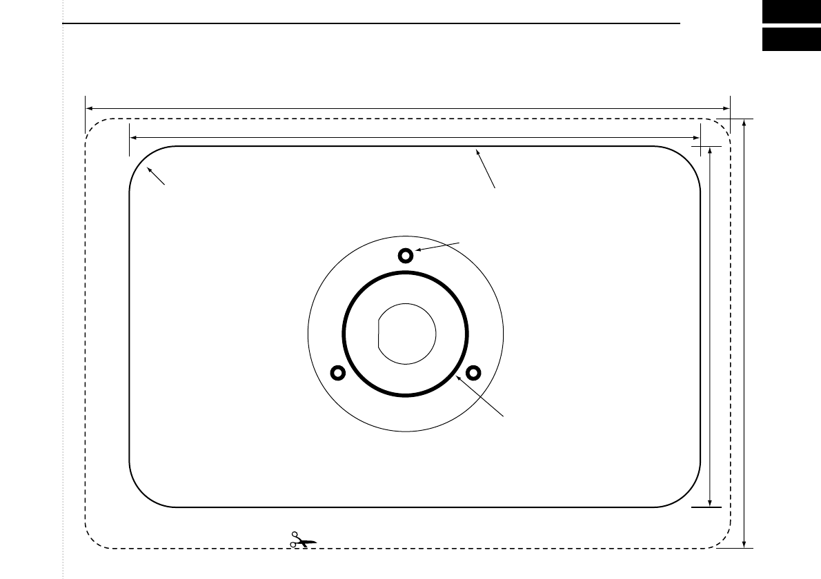
  • Icom 505 zend wel uit maar er komt geen signaal binnen. Antenne en kabel al volledig vervangen. Gesteld op 12-9-2021 om 15:44

    Reageer op deze vraag Misbruik melden
    • Hallo wij hebben ook een IC M505 in onze nieuwe bood mijn vraag is of er Nederlandstalig handleiding beschikbaar is
      Grt Gino Geantwoord op 30-9-2021 om 18:46

      Waardeer dit antwoord Misbruik melden
  • Onze marifoon IC-M505 geeft opeens geen geluid meer via de speaker van de marifoon alsook via de commander repeater buiten; ik heb daar ook een losse speaker die het ook niet doet. Zenden gaat goed, de ontvanger aan de andere kant hoort ons wel. Ook krijg ik wel het Atis signaal binnen als iemand oproept, maar ik hoor geen geluid, terwijl ik dat dan via een losse handheld marifoon wel hoor binnen komen. De marifoon doet het al een paar jaar prima. Iser een instelling waarmee ik heb abusievelijk op mute heb gezet of is er iets anders aan te doen? Gesteld op 16-5-2016 om 14:40

    Reageer op deze vraag Misbruik melden
    • Heel toevallig heb ik hetzelfde probleem. Alles is getest en is ok, maar toch hoor weinig tot niets. Alleen als de zender heel dicht de buurt is. Geantwoord op 23-6-2016 om 21:06

      Waardeer dit antwoord (1) Misbruik melden
  • is hier al iets van bekend ? weet iemand een adres waar ze dit kunnen repareren?
    Gr A.A Geantwoord op 17-8-2023 om 19:37

    Waardeer dit antwoord Misbruik melden

Misbruik melden

Gebruikershandleiding.com neemt misbruik van zijn services uitermate serieus. U kunt hieronder aangeven waarom deze vraag ongepast is. Wij controleren de vraag en zonodig wordt deze verwijderd.

Product:

Bijvoorbeeld antisemitische inhoud, racistische inhoud, of materiaal dat gewelddadige fysieke handelingen tot gevolg kan hebben.

Bijvoorbeeld een creditcardnummer, een persoonlijk identificatienummer, of een geheim adres. E-mailadressen en volledige namen worden niet als privégegevens beschouwd.

Spelregels forum

Om tot zinvolle vragen te komen hanteren wij de volgende spelregels:

Belangrijk! Als er een antwoord wordt gegeven op uw vraag, dan is het voor de gever van het antwoord nuttig om te weten als u er wel (of niet) mee geholpen bent! Wij vragen u dus ook te reageren op een antwoord.

Belangrijk! Antwoorden worden ook per e-mail naar abonnees gestuurd. Laat uw emailadres achter op deze site, zodat u op de hoogte blijft. U krijgt dan ook andere vragen en antwoorden te zien.

Abonneren

Abonneer u voor het ontvangen van emails voor uw Icom IC-M505 bij:


U ontvangt een email met instructies om u voor één of beide opties in te schrijven.


Ontvang uw handleiding per email

Vul uw emailadres in en ontvang de handleiding van Icom IC-M505 in de taal/talen: Engels als bijlage per email.

De handleiding is 1,03 mb groot.


U ontvangt de handleiding per email binnen enkele minuten. Als u geen email heeft ontvangen, dan heeft u waarschijnlijk een verkeerd emailadres ingevuld of is uw mailbox te vol. Daarnaast kan het zijn dat uw internetprovider een maximum heeft aan de grootte per email. Omdat hier een handleiding wordt meegestuurd, kan het voorkomen dat de email groter is dan toegestaan bij uw provider.

Stel vragen via chat aan uw handleiding

Stel uw vraag over deze PDF

Uw handleiding is per email verstuurd. Controleer uw email

Als u niet binnen een kwartier uw email met handleiding ontvangen heeft, kan het zijn dat u een verkeerd emailadres heeft ingevuld of dat uw emailprovider een maximum grootte per email heeft ingesteld die kleiner is dan de grootte van de handleiding.

Er is een email naar u verstuurd om uw inschrijving definitief te maken.

Controleer uw email en volg de aanwijzingen op om uw inschrijving definitief te maken

U heeft geen emailadres opgegeven

Als u de handleiding per email wilt ontvangen, vul dan een geldig emailadres in.

Uw vraag is op deze pagina toegevoegd

Wilt u een email ontvangen bij een antwoord en/of nieuwe vragen? Vul dan hier uw emailadres in.


Info