The programmed channels are differ according to versions.
01A
––
03A
––
05A
06
07A
08
09
10
11
156.050
–––
156.150
–––
156.250
156.300
156.350
156.400
156.450
156.500
156.550
156.050
–––
156.150
–––
156.250
156.300
156.350
156.400
156.450
156.500
156.550
12
13
14
15
16
17
18A
19A
20
20A
21A
156.600
156.650
156.700
156.750
156.800
156.850
156.900
156.950
157.000
157.000
157.050
156.600
156.650
156.700
156.750
156.800
156.850
156.900
156.950
161.600
157.000
157.050
22A
23A
24
25
26
27
28
37A*
61A
––
63A
157.100
157.150
157.200
157.250
157.300
157.350
157.400
157.850
156.075
–––
156.175
157.100
157.150
161.800
161.850
161.900
161.950
162.000
157.850
156.075
–––
156.175
64A
65A
66A
67
68
69
70
71
72
73
74
156.225
156.275
156.325
156.375
156.425
156.475
Rx only
156.575
156.625
156.675
156.725
156.225
156.275
156.325
156.375
156.425
156.475
156.525
156.575
156.625
156.675
156.725
77
78A
79A
80A
81A
82A
83A
84
84A
85
85A
156.875
156.925
156.975
157.025
157.075
157.125
157.175
157.225
157.225
157.275
157.275
156.875
156.925
156.975
157.025
157.075
157.125
157.175
161.825
157.225
161.875
157.275
86
86A
87
87A
88
88A
P4*
157.325
157.325
157.375
157.375
157.425
157.425
161.425
161.925
157.325
161.975
157.375
162.025
157.425
161.425
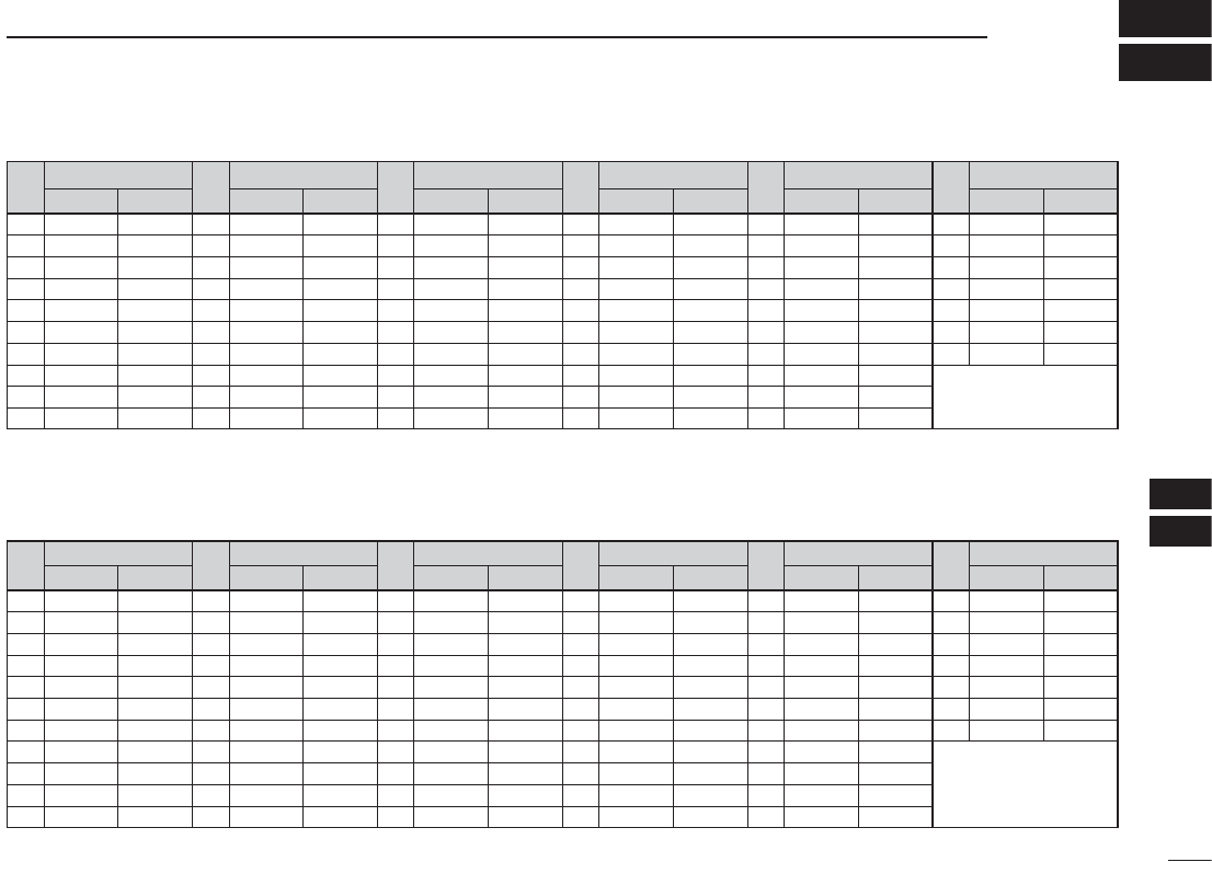
CH
Frequency (MHz)
TransmitReceive
CH
Frequency (MHz)
TransmitReceive
CH
Frequency (MHz)
TransmitReceive
CH
Frequency (MHz)
TransmitReceive
CH
Frequency (MHz)
TransmitReceive
CH
Frequency (MHz)
TransmitReceive
*
1
Channels 15 and 17 may also be used for on-board communications provided the effective radiated power does not exceed 1 W, and subject to the national
regulations of the administration concerned when these channels are used in its territorial waters.
*
2
The output power of channels 75 and 76 are limited to low power (1 W) only. The use of these channels should be restricted to navigation-related communications
only and all precautions should be taken to avoid harmful interference to channel 16, e.g. by means geographical separation.
28
SPECIFICATIONS
12
ï GENERAL
• Frequency coverage : Transmit 156.000–161.450 MHz
Receive 156.000–163.425 MHz
• Mode : FM (16K0G3E)
• Channel spacing : 25 kHz
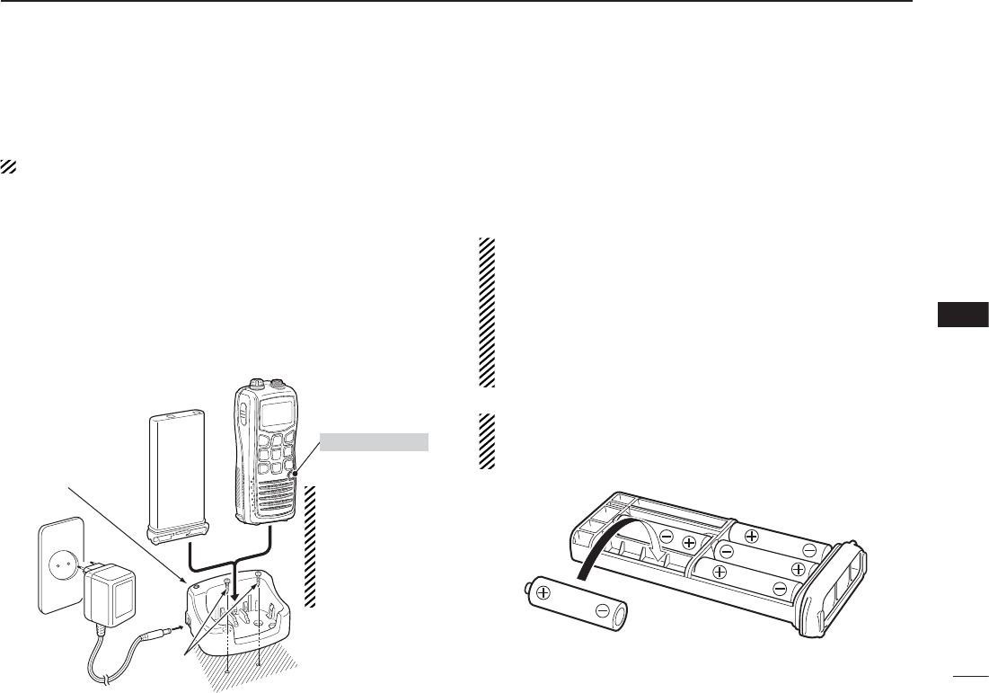
• Power supply requirement : BP-251 and BP-252 only
• Current drain (at 7.4 V DC)
TX High (6 W) : 1.5 A typical
TX Low (1 W) : 0.7 A typical
TX Low (0.5 W) : 0.6 A typical
RXMax. audio : 0.3 A typical (internal speaker)
: 0.2 A typical (external speaker)
Power save : 10 mA typical
• Frequency stability : ±1.5 kHz
• Operating temperature range : –15°C to +55°C
• Dimensions : 62 (W) × 139.5 (H) × 43 (D) mm
(Projections not included)
• Weight : Approx. 295 g
(incl. BP-252, FA-SC58V and MB-109)
ï TRANSMITTER
• Output power (at 7.4 V DC) : 6 W (High) and 1 W (Low)
( 1 W (High) and 0.5 W (Low) for German
version depending on the pre-setting.)
• Modulation system : Variable reactance frequency
Gebruikershandleiding.com neemt misbruik van zijn services uitermate serieus. U kunt hieronder aangeven waarom deze vraag ongepast is. Wij controleren de vraag en zonodig wordt deze verwijderd.
Product:
Spelregels forum
Om tot zinvolle vragen te komen hanteren wij de volgende spelregels:
lees eerst de handleiding door;
controleer of uw vraag al eerder door iemand anders is gesteld;
probeer uw vraag zo duidelijk mogelijk te stellen;
heeft u een probleem en al geprobeerd om dit op te lossen, vermeld dit erbij aub;
heeft u een oplossing gekregen van een bezoeker dan horen wij dat graag in dit forum;
wilt u een reactie geven op een vraag of antwoord, gebruik dan niet dit formulier maar klik op de knop 'reageer op deze vraag';
uw vraag wordt direct op de website gezet; vermijd daarom persoonlijke gegevens in te vullen;
Belangrijk! Als er een antwoord wordt gegeven op uw vraag, dan is het voor de gever van het antwoord nuttig om te weten als u er wel (of niet) mee geholpen bent! Wij vragen u dus ook te reageren op een antwoord.
Belangrijk! Antwoorden worden ook per e-mail naar abonnees gestuurd. Laat uw emailadres achter op deze site, zodat u op de hoogte blijft. U krijgt dan ook andere vragen en antwoorden te zien.
Abonneren
Abonneer u voor het ontvangen van emails voor uw Icom IC-M35 bij:
nieuwe vragen en antwoorden
nieuwe handleidingen
U ontvangt een email met instructies om u voor één of beide opties in te schrijven.
Ontvang uw handleiding per email
Vul uw emailadres in en ontvang de handleiding van Icom IC-M35 in de taal/talen: Engels als bijlage per email.
De handleiding is 1,72 mb groot.
U ontvangt de handleiding per email binnen enkele minuten. Als u geen email heeft ontvangen, dan heeft u waarschijnlijk een verkeerd emailadres ingevuld of is uw mailbox te vol. Daarnaast kan het zijn dat uw internetprovider een maximum heeft aan de grootte per email. Omdat hier een handleiding wordt meegestuurd, kan het voorkomen dat de email groter is dan toegestaan bij uw provider.
Stel vragen via chat aan uw handleiding
Stel uw vraag over deze PDF
Uw handleiding is per email verstuurd. Controleer uw email
Als u niet binnen een kwartier uw email met handleiding ontvangen heeft, kan het zijn dat u een verkeerd emailadres heeft ingevuld of dat uw emailprovider een maximum grootte per email heeft ingesteld die kleiner is dan de grootte van de handleiding.
Er is een email naar u verstuurd om uw inschrijving definitief te maken.
Controleer uw email en volg de aanwijzingen op om uw inschrijving definitief te maken
U heeft geen emailadres opgegeven
Als u de handleiding per email wilt ontvangen, vul dan een geldig emailadres in.
Uw vraag is op deze pagina toegevoegd
Wilt u een email ontvangen bij een antwoord en/of nieuwe vragen? Vul dan hier uw emailadres in.